

Immergas EOLO Star 23 kW Technical Documentation Manual

EOLO Star 23 kW
http://serviceimmergas.ro
Instantaneous wall-hung
with room-sealed boilers
EOLO Star 23 kW
S.C FUTURE LINE INSTAL S.R.L
str. Biharia nr.67-77, sector 1, Bucuresti, ROMANIA
serviceimmergas.ro
Dispecerat Non Stop
Tel. Fix : 021-201.11.14

http://serviceimmergas.ro
Technical Documentation
http://serviceimmergas.ro
EOLO Star 23 kW
Technical Documentation
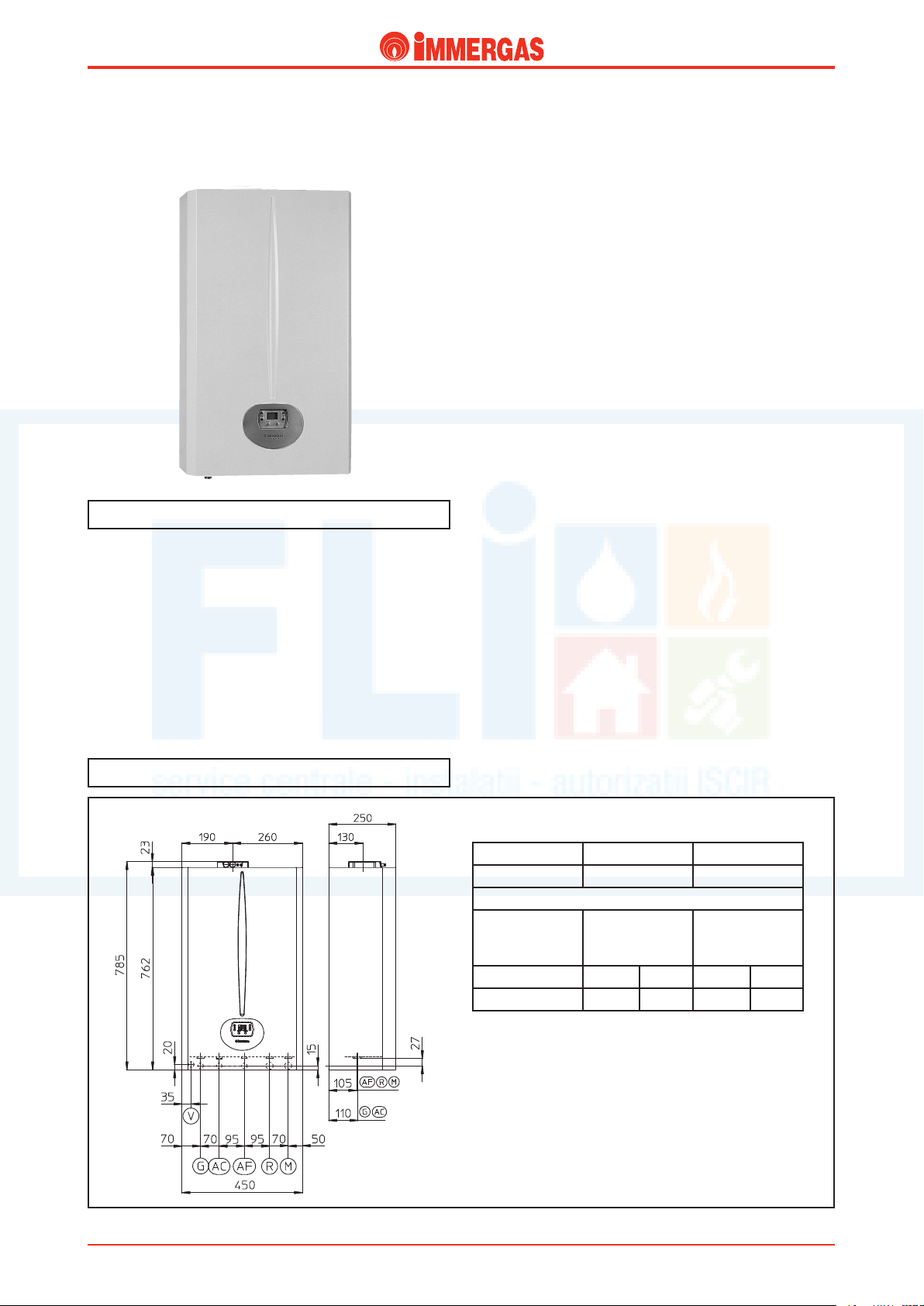
Compact instantaneous wall-hung room-sealed
(type C) fan-assisted boiler.
EOLO Star 23 kW
General features.
EOLO Star 23 kW is a wall-hung, room-sealed fan-assisted
boiler for heating and production domestic hot water.
is very compact boiler (H=785 mm, W=450 mm, D=250
mm), has an output heat of 23.3 kW (20,000 kcal/h).
A microprocessor controlled electronic board adjusts and
controls the appliance (burner ignition, temperature adjust-
ment, flame modulation and diagnostics) and, by means of a
digital interface with display and push buttons, the operating
parameters can be displayed and set.
Main dimensions and main connections.
e hydraulic circuit is equipped with a copper bithermal type
water-gas exchanger for the production of hot water for central
heating and domestic use, an automatic by-pass on the system
and a flow switch for tapping the domestic hot water.
Combustion air intake inside the sealed chamber and the
expulsion of gases are ensured by a fan. A differential pressure
switch controls correct operation.
Height (mm) Width (mm) Depth (mm)
785 450 250
CONNECTIONS
DOMESTIC
GAS
G AC
3/4” 1/2” 1/2” 3/4” 3/4”
CIRCUIT
TER
WA
AF R M
SYSTEM
STESkW ed 05/06 EOLO Star 23 kW
Legend:
G - Gas supply
AC - Hot water outlet
AF - Cold water inlet
R - System return
M - System delivery
V - Electrical supply
1
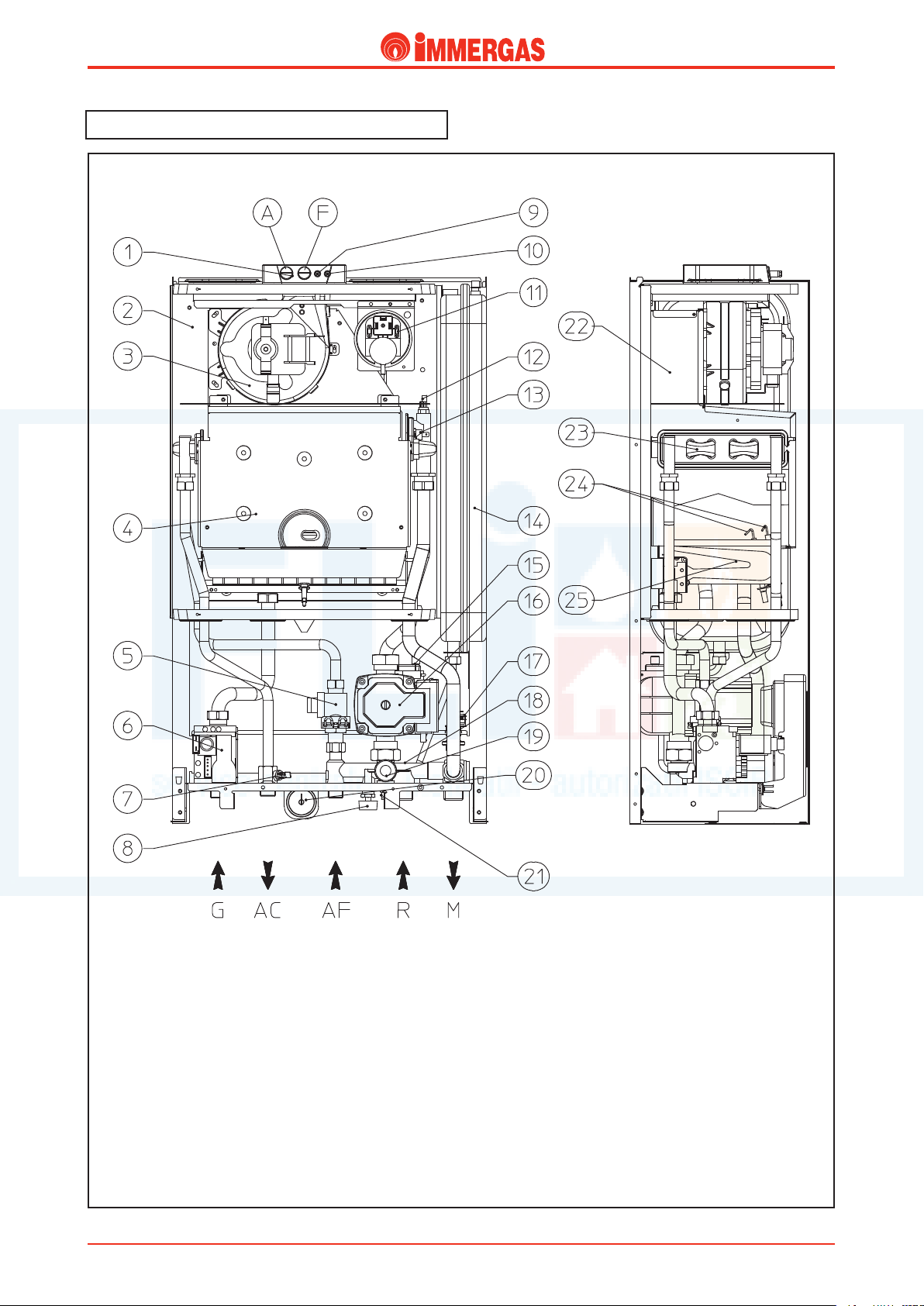
Main components.
http://serviceimmergas.ro
Technical DocumentationTechnical Documentation
Legend:
1 - Testing hole (A air) – (F flue)
2 - Sealed chamber
3 - Fan
4 - Combustion chamber
5 - D.h.w. flow switch
6 - Gas valve
7 - D.h.w. probe
8 - Filling valve
9 - Pressure point, positive signal
10 - Pressure point, negative signal
11 - Flue pressure switch
12 - Delivery probe
13 - Safety thermostat
14 - System expansion vessel
15 - Automatic air vent
STESkW ed 05/06 EOLO Star 23 kW
16 - Boiler circulator
17 - System pressure switch
18 - Manifold
19 - 3 bar safety valve
20 - Boiler pressure gauge
21 - System draining cock
22 - Draught diverter
23 - Rapid heat exchanger
24 - Ignition/detection electrodes
25 - Burner
2
Technical Documentation
http://serviceimmergas.ro
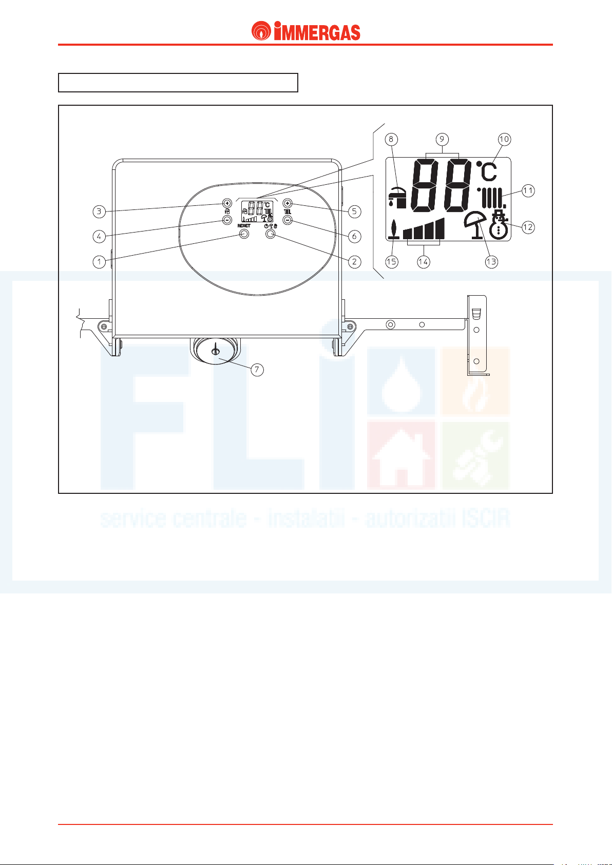
Control panel.
Technical Documentation
Legend:
1 - Reset Push Button
2 - Stand-by / Summer / Winter Push Button
3 - Push button (+) to increase d.h.w. temperature
4 - Push button (-) to reduce d.h.w. temperature
5 - Push button (+) to increase system water temperature
6 - Push button (-) to reduce system water temperature
7 - Boiler pressure gauge
8 - D.h.w. functioning mode
9 - Displays temperatures and error codes
10 - Unit of measure
11 - Central heating functioning mode
12 - Winter
13 - Summer
14 - Power supplied
15 - Burner operating
STESkW ed 05/06 EOLO Star 23 kW
3
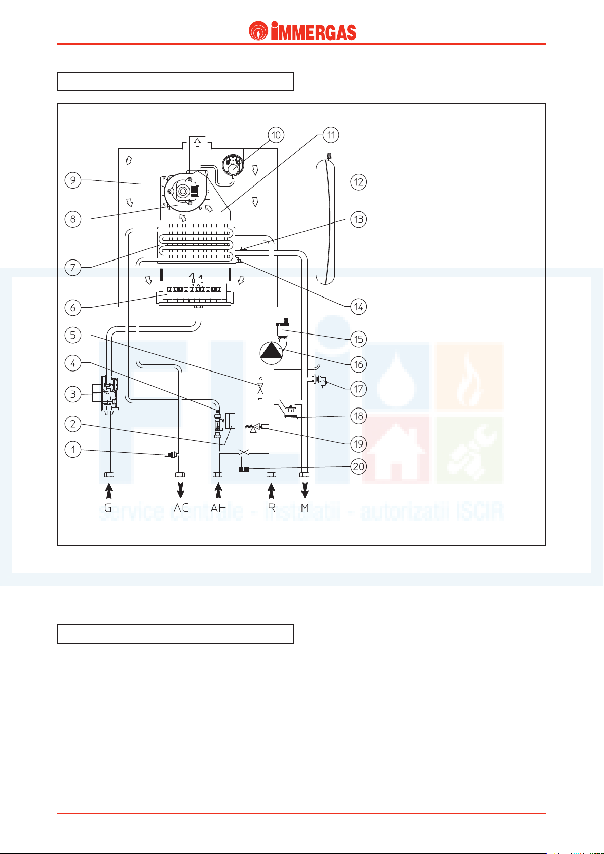
Hydraulic circuit.
http://serviceimmergas.ro
Technical DocumentationTechnical Documentation
Legend:
1 - D.h.w. probe
2 - D.h.w. flow switch
3 - Gas valve
4 - Flow limiter
5 - Draining cock
6 - Burner
7 - Rapid exchanger
8 - Fan
9 - Sealed chamber
10 - Flue pressure switch
11 - Draught diverter
12 - System expansion vessel
13 - Delivery probe
14 - Safety thermostat
15 - Automatic air vent
16 - Boiler circulator
17 - System pressure switch
18 - Automatic by-pass
19 - 3 bar safety valve
20 - Filling valve
Hot water for central heating and domestic use is produced
by two separate circuits that work as required.
Primary circuit (Boiler Circuit).
e central heating circuit, with relevant control and safety
devices, is operated every time a central heating request is
made.
G - Gas supply
AC - D.h.w. outlet
AF - Cold water inlet
R - System return
M - System delivery
ing system through the delivery (M) and return (R) pipes.
Operation.
e heat contained in the fumes produced by combustion
is absorbed by the copper blades of the water-gas exchanger
(7) which, in turn, transfers it to the water circulating inside
thanks to the boiler circulator (16).
e hot water is then transferred directly into the central heat-
STESkW ed 05/06 EOLO Star 23 kW
4
Technical Documentation
http://serviceimmergas.ro
Technical Documentation
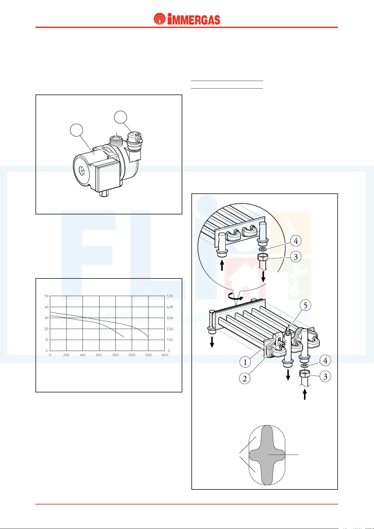
Boiler circulator (1).
e pump works on the primary circuit return and is located
on the brass manifold assembly.
It is connected to the enbloc and primary exchanger by means
of threaded fittings.
e automatic valve vent is housed on the body (2).
2
1
Primary exchanger.
is is a water-gas bithermal type blade exchanger with pipes
and fins in copper for the production of hot water for central
heating and domestic use.
(until serial number 3078554) number of fins = 79.
(from serial number 3078555) number of fins = 86.
It therefore works directly on both circuits to which it is connected by pipes with threaded fittings (3) with a flat gasket
seal (4).
e 6 oval pipes it consists of, inside which flows the water of
the central heating circuit, contain an equal number of “crossshaped” pipes for the direct transit of domestic hot water (see
illustration below).
ese pipes are plumbed in parallel in groups of three on the
central heating circuit and in series on the d.h.w. circuit.
e overheating safety thermostat (2) is fixed on the side of
the exchanger exit with a fork (1).
e relevant NTC delivery probe is screwed into place on the
central heating delivery pipe (5).
Head flow rate graph.
e available head the appliance is able to guarantee to the
system in the central heating mode depends on the flow rate
which is shown in the following graph where we can see the
characteristic curve with the pump working at second and
top speed.
O)
Head (kPa)
B
A = Head available to the system at third speed
B = Head available to the system at second speed
A
Flow rate (l/h)
Head (m H
Domestic
cold
water
inlet
2
Domestic
hot
water
outlet
Domestic
hot
water
outlet
System
deliv
ery
System
return
STESkW ed 05/06 EOLO Star 23 kW
Exchanger pipe section
System
central
heating circuit
5
D.h.w.
circuit
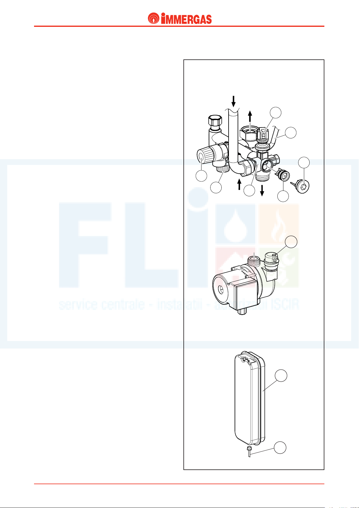
Safety devices and controls.
7
4
5
1
2
3
6
http://serviceimmergas.ro
Automatic system by-pass (4).
is device ensures circulation in the central heating circuit
even when this is prevented by the system’s high resistance.
It works between the delivery and return of the central heating
circuit and is accessible after having unscrewed the cap (5) on
the brass manifold’s hook (1).
System water pressure switch (7).
is is an absolute pressure switch that reads the pressure inside
the central heating circuit.
It is housed in the manifold (1) and coupled to a microswitch
that prevents the boiler working when the pressure measured
is below 0.3 bar.
is prevents the bithermal exchanger from overheating.
Filling valve (3).
is valve is between the boiler circuit and the domestic cold
water inlet and permits pressurisation of the central heating
system.
It is located underneath the brass manifold (1) to which it is
screwed.
Technical DocumentationTechnical Documentation
Central
heating
exchanger
ery
deliv
System
return
Pump
return
System
delivery
3-bar safety valve (2).
is valve prevents the safety pressure being exceeded in the
circuit (3 bar).
It is on the front of the manifold (1), secured to it on the side
with an Allen screw.
When this valve triggers, water exits from the boiler return
pipe.
Automatic air vent (8).
It automatically expels any gaseous substances from the circuit.
It is mounted on the pump’s delivery side.
Expansion vessel (9).
It compensates for variations in volume as a result of heating
the water which also limits pressure variations.
It has a 6-litre capacity (3.95 useful litres) and a pre-load pres-
sure of 1.0 bar.
It is located on the right of the boiler alongside the sealed
chamber and is connected to the return manifold (1) by a
copper pipe (6) with threaded fittings.
8
9
STESkW ed 05/06 EOLO Star 23 kW
6
6
Technical Documentation
1
2
3
http://serviceimmergas.ro
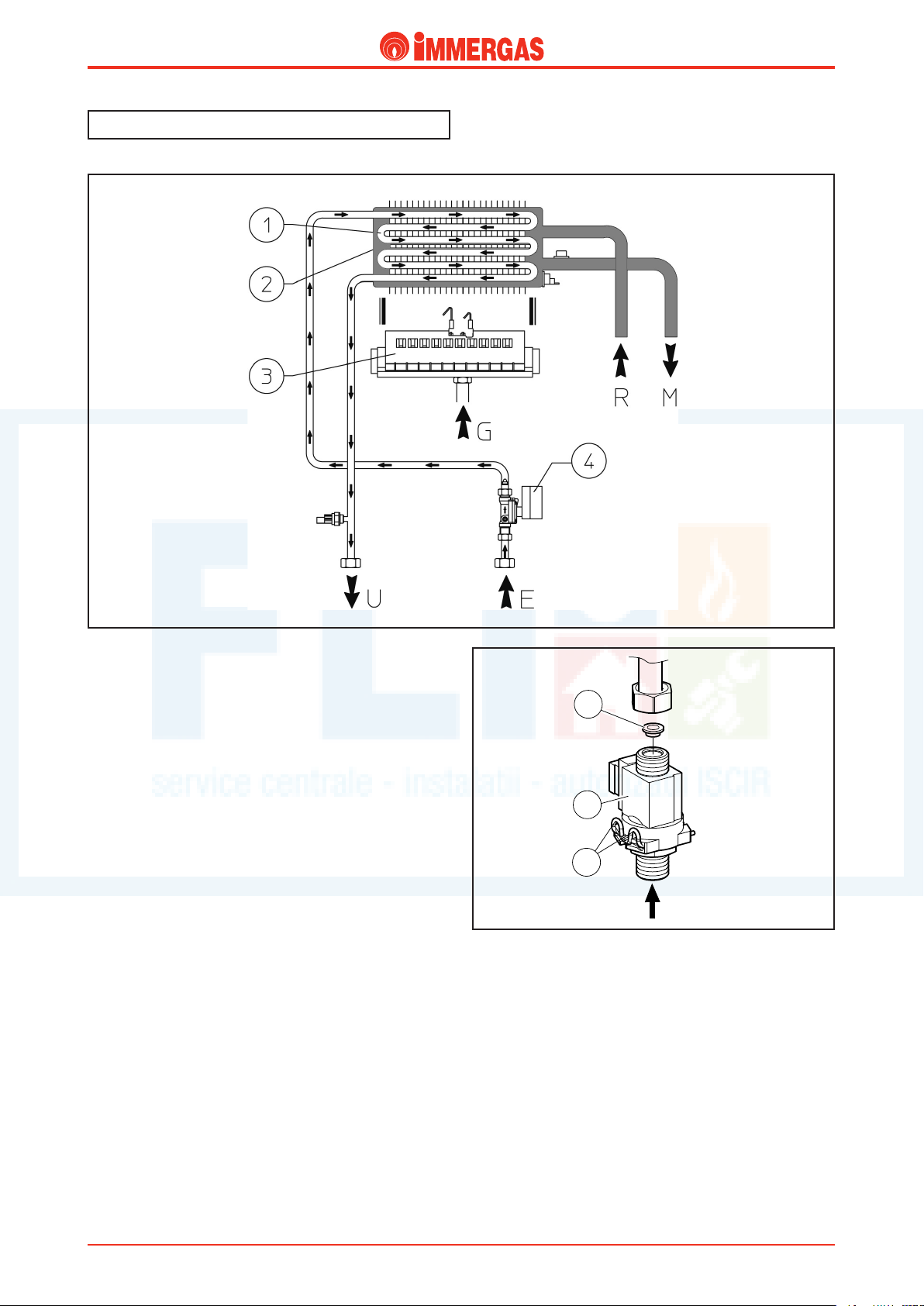
Secondary circuit (D.h.w. circuit).
Technical Documentation
Operation.
When domestic hot water is drawn, cold water flows inside
the flow switch (4) which closes the electrical contact coupled
to it (see the electrical circuit).
As a result, the adjustment circuit starts the d.h.w. priority
phase that ignites the burner (3) and, if there is an ongoing
central heating request, switches the boiler circulator off.
In this way, the heat in the fumes produced by combustion is
absorbed by the copper blades of the bithermal exchanger (2)
and transferred to the heating circuit water which, in turn,
transfers it to the domestic water circuit flowing through the
“cross-shaped” hot water circuit pipes (1).
D.h.w. flow switch.
Whenever hot water is drawn at a rate of at least 1.5 l/min and
with a dynamic pressure of 0.3 bar, the flow switch (2) enables
the boiler to operate in the d.h.w. mode.
is is done by means of a magnet that, by lifting when hit by
the flow of cold water, moves near to an electrical contact (reed
relay) causing it to move thanks to the effect of the magnet.
When the contact closes, which is located outside the pipe
through which the water flows, it enables the modulation board
to start the domestic hot water priority operating mode.
It consists of two blocks (one in brass and one in plastic) that
are coupled together and locked with a pin (3).
An 8.0 l/min (2 bar) flow limiter (1) is installed at the flow
switch exit.
Bithermal exchanger
(see the central heating circuit).
Note: to ensure long life and have an exchanger that is always
efficient, we recommend installing the “polyphosphates dispenser
kit” if the water is likely to lead to scale forming. For example,
this kit is recommended when the hardness of the water exceeds
25 French degrees.
Cold domestic
water inlet
STESkW ed 05/06 EOLO Star 23 kW
7
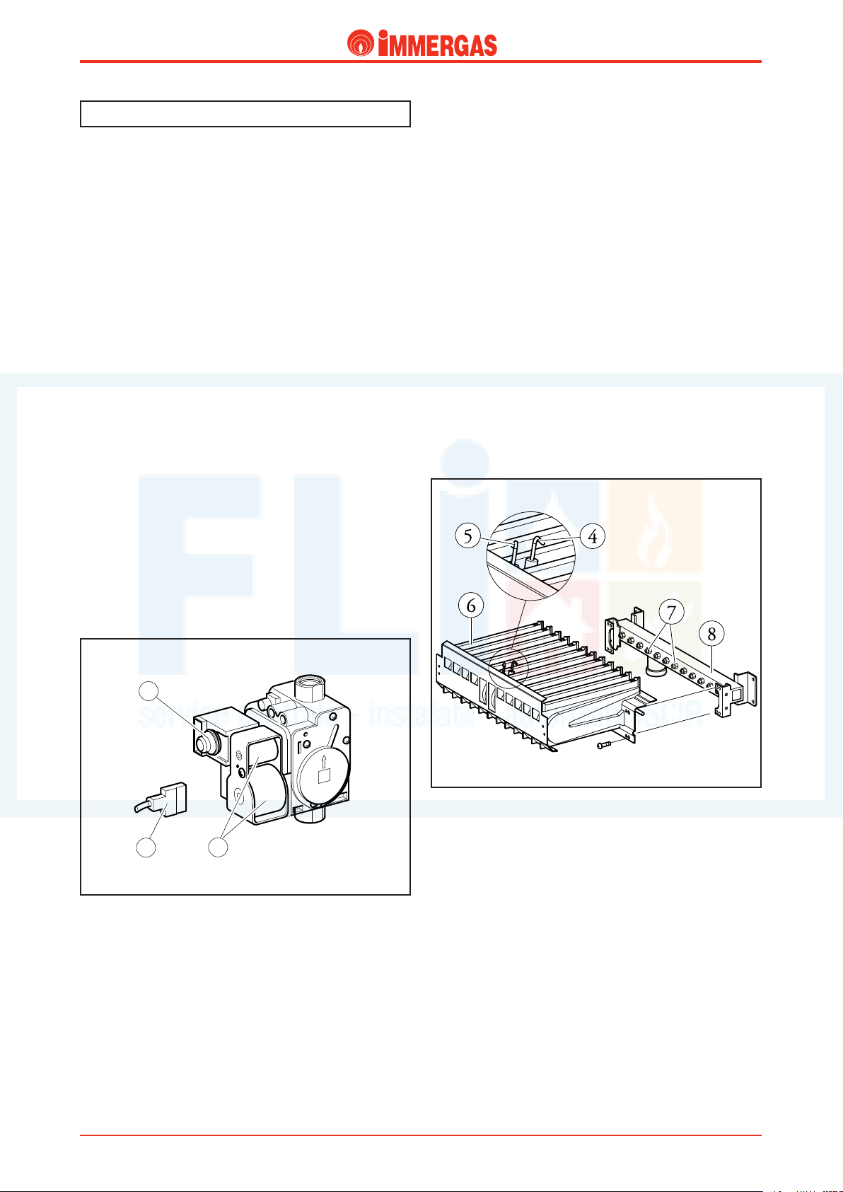
Gas circuit.
1
3
2
http://serviceimmergas.ro
Technical DocumentationTechnical Documentation
e circuit consists of an atmospheric burner and a modulating gas valve for gas combustion and flow adjustment
respectively.
Operation.
When the main coils are energised (3) both the inner valve
shutters open allowing gas to flow towards the burner.
e flow rate/outlet pressure is set by means of the gas valve
stabiliser and the modulation coil (1).
By mean of the burner nozzles (7) fuel is injected into the Venturi tubes (ramps) inside which the air-gas mixture is obtained
that is ignited by the spark from the ignition electrode (5).
Modulating gas valve.
e gas valve (SIT 845) features two main coils (3) and a
modulation coil (1) controlled by the integrated board.
e maximum and minimum outlet pressure can be set with
this valve (see gas settings).
Main electric coils (3).
ey are two ON-OFF type coils supplied (230 Vac) by the
integrated board when the burner has to be ignited.
ey are electrically connected in parallel and supplied by
mains power through a special connector (2).
Modulation coil (1).
is is a low voltage coil controlled by the integrated board.
It controls the gas valve stabiliser and permits changing of
the outlet pressure in a way proportionate to the DC running
through it.
Burner.
e burner consists of 12 horizontal Venturi tubes (6) inside
which the gas is injected by an equal number of nozzles (7)
mounted on the specific manifold (8) and whose diameter
varies according to the type of gas used (see technical data).
Ignition occurs by means of an integrated p.c.b. that controls
the ignition (5) and detection (4) electrodes.
Ignition electrode (5).
is is controlled by the integrated board that produces an
electrical charge between its end and the burner surface which
is responsible for igniting the air-gas mix.
is electrode is at the front of the burner in line with the
centre ramp.
Detection electrode (4).
is is controlled by the integrated board and detects burner
ignition.
It
is positioned at the front of the burner on the same ramp
as the ignition electrode.
STESkW ed 05/06 EOLO Star 23 kW
8
 Loading...