

Immergas DIM 2 ZONE ErP, DIM 3 ZONE ErP, DIM H-2LT ERP, DIM A-2BT ErP, DIM H-LT ERP Instructions And Warnings
...Page 1
Instructions and warnings
*1.039170ENG*
IE
ERP
MULTI-SYSTEM
DISTRIBUTION
MANIFOLD
DIM 2 ZONE ERP
DIM 3 ZONE ERP
DIM H-LT ERP (1 high-
temperature area 1 low-
temperature zone)
DIM H-2LT ERP (1 high-
temperature area 2 low-
temperature zones)
Page 2

Page 3

Dear Customer,
Our compliments for having chosen a top-quality Immergas product, able to assure well-being and safety for a long period of time. As an Immergas customer,
you can also count on a qualied Aer-Sales Service, prepared and updated to guarantee the constant eciency of your products. Read the following pages
carefully: you will be able to draw useful suggestions regarding the correct use of the appliance. By respecting these suggestions, you will no doubt be satised
with your Immergas product.
For assistance and scheduled maintenance, contact Authorised Immergas Aer-Sales centres: they have original spare parts and are specically trained directly
by the manufacturer.
General recommendations
All Immergas products are protected with suitable transport packaging.
e material must be stored in dry environments protected from bad weather.
e instruction book is an integral and essential part of the product and must also be given to the new user in the case of transfer or succession of ownership.
It must be stored with care and consulted carefully, as all of the warnings provide important safety indications for installation, use and maintenance stages.
is instructions manual provides technical information for installing Immergas appliances. As for the other issues related to the installation of appliances
(e.g. safety in the workplace, environmental protection, injury prevention), it is necessary to comply with the provisions of the regulations in force and the
principles of good practice.
In compliance with the legislation in force, the systems must be designed by qualied professionals, within the dimensional limits established by the Law.
Installation and maintenance must be performed in compliance with the regulations in force, according to the manufacturer's instructions and by professionally
qualied sta, intending sta with specic technical skills in the plant sector, as envisioned by the Law.
Improper installation or assembly of the Immergas appliance and/or components, accessories, kit and devices can cause unexpected problems for people, animals
and objects. Read the instructions provided with the product carefully to ensure proper installation.
Maintenance must be carried out by skilled technical sta. e Authorised Aer-Sales Service represents a guarantee in terms of qualications and professionalism.
e appliance must only be destined for the use for which it has been expressly declared. Any other use will be considered improper and therefore potentially
dangerous.
If errors occur during installation, operation and maintenance, due to non-compliance with technical laws in force, standards or instructions contained in
this book (or however supplied by the manufacturer), the manufacturer is excluded from any contractual and extra-contractual liability for any damages and
the appliance warranty is invalidated.
For further information regarding legislative and statutory provisions relative to the installation of gas heat generators, consult the Immergas site at the
following web address: www.immergas.com
CE DECLARATION OF CONFORMITY
(according to ISO/IEC 17050-1)
e company IMMERGAS S.p.A., with registered oce in via Cisa Ligure 95 42041 Brescello (RE), whose design, manufacturing and aer-sales assistance
processes comply with the requirements of standard UNI EN ISO 9001:2008,
e multi-system hydraulic manifolds DIM 2 ZONE ERP, DIM 3 ZONE ERP, DIM H-2LT ERP, DIM H-2LT ERP comply with the following European
Directives and Delegated European regulations:
“Eco-design” Directive 2009/125/EC, “Energy labelling” Directive 2010/30/EC, EU Regulation 811/2013, EU Regulation 813/2013, “Electromagnetic
Compatibility” Directive 2004/108/EC, “Eciency” Directive 92/42/EC and “Low-Voltage” Directive 2006/95/EC.
Immergas S.p.A. declines all liability due to printing or transcription errors, reserving the right to make any modications to its technical and commercial
documents without prior notice.
DECLARES that:
Mauro Guareschi
Research & Development Director
Signature:
Page 4

INDEX
USER pageINSTALLER page MAINTENANCE TECHNICIAN page
1 Installing the device ....................................5
1.1 Description of the device. .......................... 5
1.2 Installation recommendations. ................. 5
1.3 Main dimensions. ......................................6
1.4 Hydraulic connection. ................................7
1.5 Electrical connection. ................................7
1.6 Installation layouts......................................8
1.7 Commissioning the device. .....................10
1.8 Circulation pump......................................10
1.9 Sizing the systems. ....................................10
1.10 Kits available on request. .........................10
1.11 Main components. ....................................12
2 Use and maintenance instructions .........14
2.1 General warnings. ..................................... 14
2.2 Warnings for the user. ..............................14
2.3 Cleaning the case. ..................................... 14
3 Checks and maintenance .........................15
3.1 Wiring diagram DIM 2 zone ErP. ........... 16
3.2 Wiring diagram DIM 3 zone ErP. ........... 17
3.3 DIM H-LT ErP Wiring diagram. ............18
3.4 DIM H-2LT ErP Wiring diagram. ..........19
3.5 DIM connection to boiler via IMG BUS. 20
3.6 DIM connection to boiler via zone
signal state..................................................21
3.7 DIM connections to ON/OFF room
thermostats. ...............................................22
3.8 DIM connections to ON/OFF room
thermostats and C.A.R.V2 /
SUPER C.A.R. remote controls. ..............24
3.9 DIM connections to ON/OFF room
thermostats and C.A.R.V2 or C.A.R
Universal remote control. ........................24
3.10 Connection between 2 DIM with
hydraulics in parallel. ...............................25
3.11 DIM connection to another DIM
or to Hercules zone kit with
hydraulics in series. ..................................27
3.12 Description of main functions. ...............28
3.13 Zone management P.C.B. ......................... 28
3.14 External temperature probe (Optional). 29
3.15 Troubleshooting. .......................................29
3.16 Technical data. ..........................................30
Page 5

INSTALLING
1
THE DEVICE
1.1 DESCRIPTION OF THE DEVICE.
e “DIM” code (Disgiuntore Idrico Multi-impianti) identies a series of kits that Immergas
proposes for the management of mixed zone
central heating systems with large water capacities. In particular, they are kits that can only
be coupled with some boiler models in the
Immergas range, including an open manifold
(distribution manifold) and are available in four
dierent congurations:
• DIM 2 zones ErP, to be used to manage systems
divided into 2 zones;
• DIM 3 zones ErP, to be used to manage systems
divided into 3 zones;
• DIM H-LT ErP, for the management of mixed
systems with dierentiated temperature (e.g. a
zone with radiators and one with radiant oor
panels);
• DIM H-2LT ErP, for the management of mixed
systems with dierentiated temperature (e.g. a
zone with radiators and two with radiant oor
panels);
IMPORTANT: the boiler models set up for coupling
with the manifolds are Immergas boilers with P.C.B.
designed for the management of zone systems.
ese kits are characterised by the possibility
to be recessed into the wall, therefore they have
no clearance.
Each zone served by the manifold is managed
by a room chrono-thermostat connected to the
DIM. Whenever envisioned by the boiler, it is
possible to use an Immergas Remote control to
control one of the system zones (successively
called main zone).
1.2 INSTALLATION
RECOMMENDATIONS.
e place of installation of the appliance and
relative Immergas accessories must have suitable
features (technical and structural), such as to allow for (always in safe, ecient and comfortable
conditions):
- installation (according to the provisions of the
technical legislation and technical regulations);
- maintenance operations (including scheduled,
periodic, routine and special maintenance);
- removal (outdoors in the place for loading and
transporting the appliances and components)
as well as their eventual replacement with
appliances and/or equivalent components.
Only professionally qualified companies are
authorised to install the Immergas Multi-System Distribution Manifold. Installation must be
carried out according to regulation standards,
current legislation and in compliance with local
technical regulations and the required technical
procedures. Before installing the device, ensure
that it is delivered in perfect condition; if in
doubt, contact the supplier immediately. Packing
materials (staples, nails, plastic bags, polystyrene
foam, etc.) constitute a hazard and must be
kept out of the reach of children. In the event
of malfunctions, faults or incorrect operation,
turn the device o immediately and contact an
authorised company (e.g. the Authorised Technical Assistance Centre, which has specically
trained sta and original spare parts). Do not
attempt to modify or repair the appliance alone.
Failure to comply with the above implies personal
responsibility and invalidates the warranty.
1-1
3
2
Recess installation.
Perform the masonry work, creating an opening
in the wall suitable to contain the device (See par.
"Main dimensions").
Insert the distribution manifold (1) into its seat,
remembering to open the four support ns (2)
before insertion (Fig. 1-1).
Protect the side edges and the front cover during
recess preparation for the device.
IMPORTANT: the hydraulic and electrical connections must be made within the device unit;
you must therefore position the frame rst and
then perform the connections.
Attention: the recessed frame is not a supporting
structure and cannot replace the piece of wall
removed. It is therefore necessary to check the
correct positioning inside the wall.
Wall-hanging installation.
Fasten the frame to the wall using four expansion
plugs, suitable for the type of wall and weight
of the device (not supplied) and using the four
drilled holes (see Fig. 1-2 pos. X).
Use the fairlead and the sheath-holder (3)
supplied to limit the inltration of water inside
the frame.
INSTALLERUSER
2
1
MAINTENANCE TECHNICIAN
5
Page 6
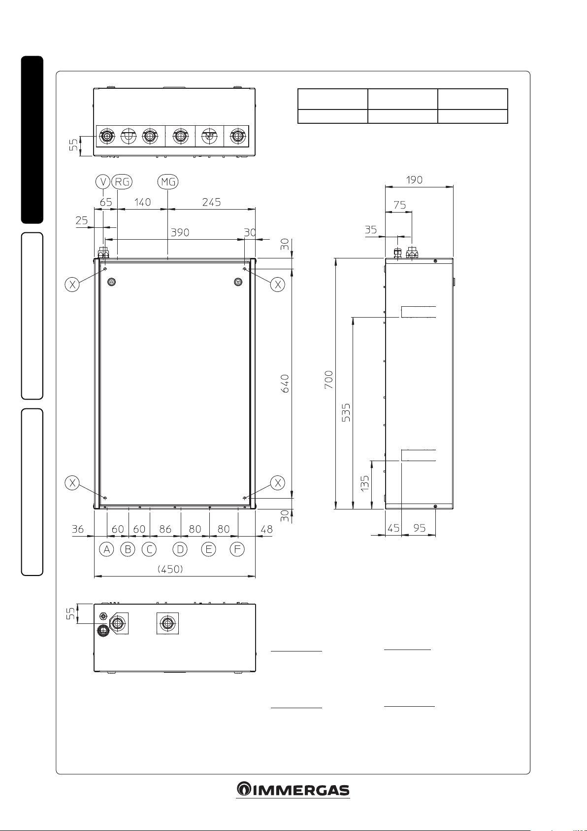
1.3 MAIN DIMENSIONS.
1-2
INSTALLERUSER
Height
(mm)
700 450 190
Width (mm) Depth (mm)
MAINTENANCE TECHNICIAN
Key:
RG - Generator return (G 3/4”)
MG - Generator ow (G 3/4”)
V - Electrical connection
X - Holes for DIM wall-mounted
fastening
DIM 2 Zone ErP
A - Zone return 1 (G 3/4”)
C - Zone return 2 (G 3/4”)
D - Zone ow 2 (G 3/4”)
F - Zone ow 1 (G 3/4”)
DIM 3 Zone ErP
A - Zone return 1 (G 3/4”)
B - Zone return 3 (G 3/4”)
C - Zone return 2 (G 3/4”)
D - Zone ow 2 (G 3/4”)
E - Zone ow 3 (G 3/4”)
F - Zone ow 1 (G 3/4”)
6
DIM H-LT ErP
A - High return temperature (G 3/4”)
B - Low return temperature (G 1”)
E - Low ow temperature (G 1”)
F - High ow temperature (G 3/4”)
DIM H-2LT ErP
A - High return temperature (G 3/4”)
B - Zone 1 low return temperature (G 1”)
C - Zone 2 low return temperature (G 1”)
D - Zone 1 low ow temperature (G 1”)
E - Zone 2 low ow temperature (G 1”)
F - High ow temperature (G 3/4”)
Page 7
1.4 HYDRAULIC CONNECTION.
Attention: before making the appliance connec-
tions, clean the heating system thoroughly (pipes,
radiators, etc.) with special pickling or de-scaling
products to remove any deposits that could
compromise the correct operation of the device.
A chemical treatment of the thermal system water is required, in compliance with the technical
standards in force, in order to protect the system
and the appliance from deposits (e.g., lime scale),
slurry or other hazardous deposits.
e hydraulic connections must be made in a
rational manner using the values as per Fig. 1-2.
IMPORTANT: remove all the protection caps
from the system ow and return pipes before
making the hydraulic connections.
e connections can be made directly using the
female couplings on the distribution manifold
or by inserting system cut-o cocks (optional).
ese cocks are particularly useful for maintenance as they allow you to drain the distribution
manifold separately without having to empty the
entire system.
N.B.: Immergas does not supply the G1” cocks to
be installed in the low-temperature zone.
Check that the expansion vessel in the boiler
allows for the increase in volume of the water
resulting from its central heating without opening the safety valve. If this is not the case, an
expansion vessel with appropriately dimensioned
capacity must be installed on the system.
e DIM is set up for the insertion of the automatic “jolly” vent valve to be mounted on the
manifold. is is recommended for better air
venting inside the system.
If two DIM devices are installed in parallel, two
manual valves must be tted in order to ensure
the correct balance of the hydraulic circuit.
1.5 ELECTRICAL CONNECTION.
e appliance has an IPX5D protection degree;
electrical safety of the appliance is achieved only
when it is connected properly to an ecient
earthing system, as specied by current safety
standards.
Attention: Immergas S.p.A. declines any responsibility for damage or physical injury caused by
failure to connect the boiler to an ecient earth
system or failure to comply with the reference
standards.
Moreover, ensure that the electrical installation
corresponds to the maximum absorbed power
specications as shown on the recessed unit data
plate. e distribution manifold is supplied complete with an “X” type power cable without plug.
e power supply cable must be connected to a
230V ±10% / 50Hz mains supply respecting L-N
polarity and earth connection; this network
must also have a multi-pole circuit breaker with
class III over-voltage category.
To protect from possible dispersions of DC voltage, it is necessary to provide a type A dierential
safety device.
When replacing the power supply cable, contact a
qualied company (e.g. the Immergas Authorised
Aer-Sales Technical Assistance Service).
For the main power supply to the appliance,
never use adapters, multiple sockets or extension leads.
Important: it is mandatory to prepare two electrical connection lines in order to separate the
power supply of each distribution manifold from
all other low-voltage connections, according to
the standards in force regarding electrical systems. ese lines must arrive inside the recessed
frame via relevant sheaths or ducts, passing
through the fairlead and the sheath-holder supplied and located on the upper side of the device.
• Connecting the boiler P.C.B. is connection
(low-voltage) ensures the dialogue between
the boiler and the DIM. Make the connections
as indicated in chapter 3, according to your
appliance model.
N.B.: the electrical connection between the
electronic boards must be made using cables
with a minimum section of 0.50 mm2 and a
maximum section of 2.5 mm2; the length of
these connections must not exceed 15 metres.
• Room thermostat connection On - O. e
room thermostats to be connected to the DIM
must have a potential free contact. e On-O
room thermostats relative to the zones must be
connected as indicated in Fig. 3-8 or 3-9.
• Immergas remote control connection.
Connect the remote controls as indicated in
gures 3-11, 3-12 and as specied in the boiler
instruction manual.
• External probe connection (optional). e
external probe controls the ow temperature of
the system and varies the operation mode and
controlled zones depending on its connection
(see par. 3.14).
- e external probe must be connected to
the boiler by connecting the manifold and
the boiler via IMG BUS. (fig. 3-5). The
temperature read by the external probe is
sent to the manifold via bus. e manifold
will then adjust the ow temperature of the
various zones, according to the settings of the
trimmer and area management probe.
- e external probe must be connected to
the manifold by connecting the manifold
and boiler via signal state. is way, it will
be possible to adjust the ow temperature of
the mixed zones. In these conditions, another
probe must be connected to the boiler if it is
necessary to correlate the direct zone ow
with the external temperature (see Fig. 3-6).
INSTALLERUSER
MAINTENANCE TECHNICIAN
7
Page 8
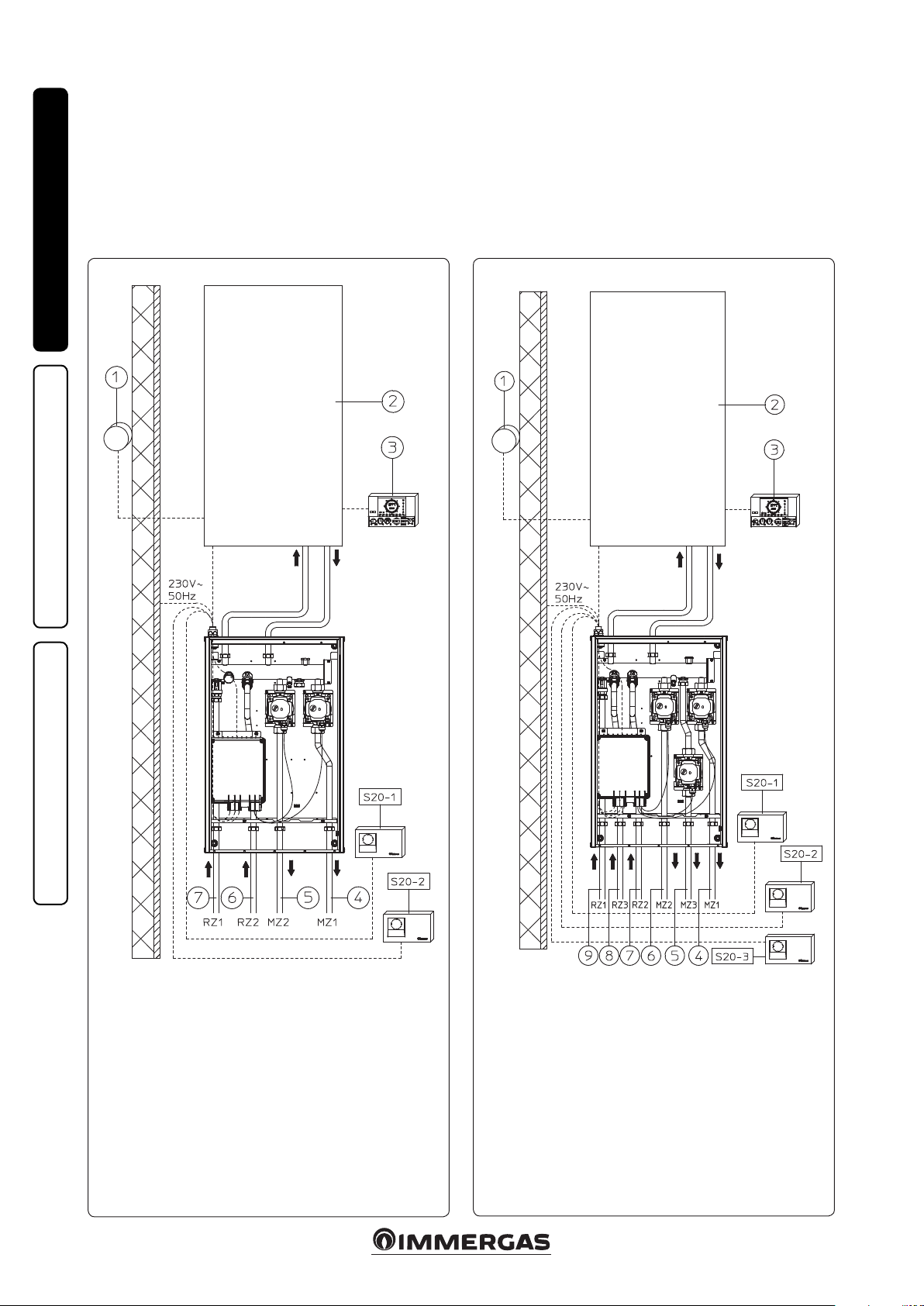
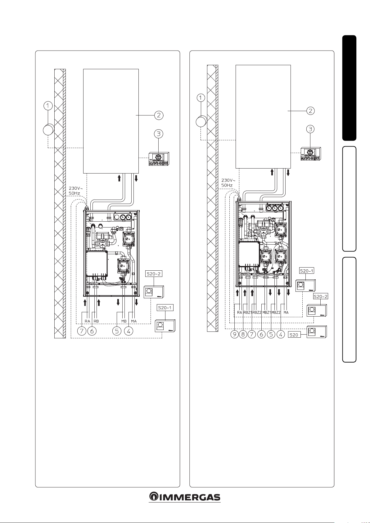
1.6 INSTALLATION LAYOUTS.
If you are using a Comando Amico Remoto V2
(C.A.R.V2) or Super C.A.R. zone control remote
control, it must be connected directly to the
boiler (see instructions in boiler manual). e
chrono-thermostat will control the pre-dened
zone on the manifold as the main zone.
e C.A.R.V2 or Super C.A.R. remote control
must be set with on-o operation (see the relative
instruction manual).
In this case, the T.A. electric connections of the
zone, dened as the main zone of the manifold,
must be le free.
Installation layout of 2 homogeneous zones. Installation layout with 3 zones in High Temperature or 3 zones in Low
INSTALLERUSER
1-3
Temperature.
1-4
MAINTENANCE TECHNICIAN
Key:
S20-1 - Room thermostat zone 1
S20-2 - Room thermostat zone 2
1 - External probe (optional)
2 - Boiler
3 - Comando Amico RemotoV2 or Super C.A.R. remote control
(optional)
4 - Flow to zone 1 system
5 - Flow to zone 2 system
6 - Return from zone 2 system
7 - Return from zone 1 system
Factory settings dene zone 1 as the main zone.
(See g. 3-1 for electrical connection and zone board setting)
Key:
S20-1 - Room thermostat zone 1
S20-2 - Room thermostat zone 2
S20-3 - Room thermostat zone 3
1 - External probe (optional)
2 - Boiler
3 - Comando Amico RemotoV2 or Super C.A.R. remote control
(optional)
4 - Flow to zone 1 system
5 - Flow to zone 3 system
6 - Flow to zone 2 system
7 - Return from zone 2 system
8 - Return from zone 3 system
9 - Return from zone 1 system
Factory settings dene zone 1 as the main zone.
(See g. 3-2 for electrical connection and zone board setting)
8
Page 9
DIM A-BT installation layout (1 zone in H. T. and 1 zone in L. T.).
DIM H-2LT installation layout (1 zone in H. T. and 2 zone in L. T.).
1-5 1-6
INSTALLERUSER
Key:
S20-1 - Zone 1 room thermostat (high temperature)
S20-2 - Zone 2 room thermostat (low temperature)
1 - External probe (optional)
2 - Boiler
3 - Comando Amico RemotoV2 remote control (optional)
4 - High-temperature system ow
5 - Low-temperature system ow
6 - Return from Low-Temperature system
7 - High-temperature system return
Factory settings dene zone 2 as the main zone.
(See g. 3-3 for electrical connection and zone board setting)
Key:
S20 - High-temperature zone room thermostat
S20-1 - Low-temperature zone 1 room thermostat
S20-2 - Low-temperature zone 2 room thermostat
1 - External probe (optional)
2 - Boiler
3 - Comando Amico RemotoV2 remote control (optional)
4 - High-temperature system ow
5 - Zone 2 Low-Temperature system ow
6 - Zone 1 Low-Temperature system ow
7 - Zone 2 Low-Temperature system return
8 - Zone 1 Low-Temperature system return
9 - High-temperature system return
Factory settings dene zone 2 as the main zone.
(See g. 3-4 for electrical connection and zone board setting)
9
MAINTENANCE TECHNICIAN
Page 10

1.7 COMMISSIONING THE DEVICE.
System lling. Once the device is connected, ll
the system via the boiler lling valve.
Filling is performed at low speed to ensure the
release of air bubbles in the water via the boiler
and central heating system vents and the distribution manifold (if any).
Close radiator vent valves when only water
escapes from them.
Close the lling cock when the boiler pressure
gauge indicates approx. 1.2 bar.
IMPORTANT: during these operations, start
INSTALLERUSER
the circulation pumps by acting on the main
switch positioned on the boiler control panel
aer having activated the T.A. devices relating
to the various zones.
(Only for DIM H-LT and H-2LT).
Act manually on the 3-way mixing vale using the
relevant lever on the electric actuator, keeping the
same opening in order to de-aerate the system
and, if necessary, control the correct operating
pressure.
Once these operations are complete, make sure
that the lever on the electric actuator is free from
the manual lock position.
1.8 CIRCULATION PUMP.
e pump is ideal for the requirements of each
central heating system in a domestic and residential environment. In fact, the pump is equipped
with electronic control that allows you to set
advanced functions.
Adjustments. Turn the selector and position it on
the desired curve to adjust the circulator pump.
Program LED
P 1 lower (ΔP-V)
P 2 upper (ΔP-V)
C 3 lower (ΔP-C) - H=3 m
C 4 upper (ΔP-C) - H=4 m
Min. - Max. blue
MAINTENANCE TECHNICIAN
green
orange
- Program P (1 lower 2 upper ) (P-V) - Pro-
portional curve (green LED). This allows
the pressure level (head) to be proportionally
reduced as the system heat demand decreases
(ow rate reduction). anks to this function,
the electric power consumption of the circulator pump is reduced further: the energy
(power) used by the pump decreases according to the pressure level and ow rate. With
this setting, the pump guarantees optimal
performance in most heating systems, thereby
being particularly suitable in single-pipe and
two-pipe installations. Any noise originating
from the water ow in the pipes, valves and
radiators is eliminated by reducing the head.
Optimal conditions for thermal comfort and
acoustic well-being.
- Programs C (3 lower 4 upper ) (P-C) Constant curve (orange LED). e circulator
pump maintains the pressure level (head)
constant as the system heat demand decreases
(ow rate reduction). With these settings, the
circulator pump is suitable for all oor systems
where all the circuits must be balanced for the
same drop in head.
- MIN. - MAX. program (blue LED). e pump
is distinguished by adjustable operating curves
by positioning the selector in any point between
the Min. and Max. positions, thereby satisfying
any installation requirement (from a simple
single-pipe to more modern and sophisticated
systems) and always guaranteeing optimum
performance. e precise working point can be
selected in the entire eld of use by gradually
adjusting the speed.
Real-time diagnostics: a lit LED (in various
colours) provides information regarding the
pump operating status, see g. 1-7
Possible pump release. The pump block is
indicated by a xed red LED switching on. Turn
the selector up to the MAX. position, disconnect
and reconnect the power to restart the automatic
release process. e pump will then activate the
procedure, which will last for a maximum of
15 minutes and the LED will ash upon each
restart. It then turns blue for a few seconds and
goes back to red if the attempt to restart is not
successful. Once the process is complete, position
the selector back on the desired curve and if the
problem has not been resolved, perform the
manual release procedure as described below.
- Disconnect the power to the boiler (the LED
switches o).
- Close the system ow and return and allow the
pump to cool down.
- Empty the system circuit via the relative cock.
- Remove the motor and clean the impeller.
- Once unblocked, remount the motor.
- Fill the primary circuit; restore boiler power
and set the desired curve.
Attention: a scalding hazard is present due to
high uid temperatures and pressures. Scalding
hazard as a result of contact.
1.9 SIZING THE SYSTEMS.
e ow temperatures to the various system
zones may be reduced with respect to the boiler
outlet temperatures, according to the mixture
of the ow and return uids inside the DIM. In
the event that the DIM is used to feed Low-Temperature zones, check that the design parameters
allow you to achieve a maximum surface temperature of the radiant oor in compliance with
standard UNI EN 1264.
1.10 KITS AVAILABLE ON REQUEST.
• System cut-o cock kit (on request). e manifold is designed for the installation of system
interception cocks, to be placed on the ow
and return pipes of the connection assembly.
is kit is particularly useful for maintenance
as it allows the DIM to be drained separately
without having to empty the entire system.
• External probe kit.
• Safety thermostat kit.
• By pass kit for H-LT and H-2LT. versions.
e above-mentioned kits are supplied complete
with instructions for assembly and use.
Circulating pump
LED
LED steady on
Flashing white LED Noises during cir-
LED steady on Flow rate too high Reduce rotation speed
LED o
Red LED
Description Diagnostics Remedy
Pump
noisy
culation of the heat
transfer uid
e circulator does
not work
Insucient system pressure, circulating pump
in cavitation
Presence of foreign matter in the impeller Remove the motor and clean the impeller
Presence of air in the system Vent the system
Power outage
Faulty circulating pump Replace the circulating pump
Rotor seized Remove the motor and clean the impeller
Insucient power supply voltage Check boiler power supply voltage
Restore correct thermal circuit pressure
Ensure the boiler is correctly powered, ensure
the circulator is correctly powered
10
1-7
Page 11

Head available to the direct zone system xed speed.
High-temperature zone
1-8
A
Head (kPa)Head (kPa)
Low-temperature zone
A
MAX
Flow rate (l/h)
MAX
Flow rate (l/h)
MIN
MIN
Key:
A = Available head
B
B = Power absorbed by the circulator
pump (dotted area)
INSTALLERUSER
Circulator pump absorbed power (W)Circulator pump absorbed power (W)
B
Head available to the direct zone system proportional or constant speed.
High-temperature zone
C
D
Head (kPa)Head (kPa)
I
Flow rate (l/h)
Low-temperature zone
C
D
E
I
G
H
E
L
F
G
H
L
F
Key:
C = Head available to the system with circula-
tor pump selector in position C4 (standard
setting)
D = Head available to the system with circula-
tor pump selector in position C3
E = Head available to the system with circula-
tor pump selector in position P2
F = Head available to the system with circula-
tor pump selector in position P1
G = Circulator pump power with selector in
position C4 (standard setting)
H = Circulator pump power with selector in
Circulator pump absorbed power (W)Circulator pump absorbed power (W)
position C3
I = Circulator pump power with selector in
position P2
L = Circulator pump power with selector in
position P1
1-9
MAINTENANCE TECHNICIAN
Flow rate (l/h)
11
Page 12

1.11 MAIN COMPONENTS.
INSTALLERUSER
DIM 2 Zone
1-10
Key:
1 - Hydraulic manifold
2 - Drain tting
3 - Zone 1 pump
4 - Electrical connection box
5 - Zone 1 ''Europa'' one-way valve
6 - Zone 2 pump
7 - Zone 2 ''Europa'' one-way valve
MAINTENANCE TECHNICIAN
DIM 3 Zone
1-11
Key:
1 - Hydraulic manifold
2 - Drain tting
3 - Zone 1 pump
4 - Electrical connection box
5 - Zone 1 ''Europa'' one-way valve
6 - Zone 2 pump
7 - Zone 3 pump
8 - Zone 3 ''Europa'' one-way valve
9 - Zone 2 ''Europa'' one-way valve
12
Page 13

DIM A-BT
1-12
INSTALLERUSER
Key:
1 - Flow temperature thermometers
2 - Hydraulic manifold
3 - Drain tting
4 - Zone 1 pump
5 - Zone 2 ow probe
6 - Zone 2 safety thermostat
7 - Electrical connection box
8 - Zone 2 3-way mixing valve
9 - Zone 2 mixing valve motor
10 - Zone 2 pump
11 - Zone 1 "Europa" one-way valve
DIM 1 zone H-2LT
Key:
1 - Flow temperature thermometers
2 - Hydraulic manifold
3 - Drain tting
4 - High-temperature zone pump
5 - Zone 2 low-temperature safety thermo-
stat
6 - Zone 2 low-temperature ow probe
7 - Electrical connection box
8 - Low-temperature zone 1 3-way mixing
valve
9 - Low-temperature zone 1 mixing valve
motor
10 - Low-temperature zone 2 3-way mixing
valve
11 - Low-temperature zone 1 safety thermo-
stat
12 - Low-temperature zone 1 ow probe
13 - Low-temperature zone 1 circulator
14 - High-temperature zone "Europa" one-
way valve
15 - Low-temperature zone 2 mixing valve
motor
16 - Low-temperature zone 2 circulator
1-13
MAINTENANCE TECHNICIAN
13
Page 14

USE AND MAINTENANCE
2
INSTRUCTIONS
2.1 GENERAL WARNINGS.
If the device must be deactivated temporarily,
act directly on the main switch to power o the
system and work safely
• Attention: using any components that use
electrical power requires the observation of
some fundamental rules:
- do not touch the device with wet or moist parts
INSTALLERUSER
of the body; do not touch when barefoot.
- if the device is wall-mounted: do not pull the
electric cables, do not leave the device exposed
to the elements (rain, sun, etc.);
- the device power cable must not be replaced by
the user;
- in the event of damage to the cable, switch the
device o and exclusively contact professionally
qualied sta for replacement;
- if the device is not going to be used for a certain
period, disconnect the main power switch.
2.2 WARNINGS FOR THE USER.
is device does not require any regulation or
control by the user; the opening of the device front
lid is therefore prohibited.
e only operation that the user must perform is
that of periodically checking the water pressure of
the system in the boiler. e boiler pressure gauge
should read a value of between 1 and 1.2 bar.
If the pressure is below 1 bar (with the circuit cool),
restore normal pressure via the lling v alve located
in the boiler (see boiler instruction book).
N.B.: close the valve aer the operation.
If pressure values reach around 3 bar, the boiler
safety valve may be activated.
In this case, remove water from a radiator air
vent valve until a pressure of 1 bar is achieved,
or ask for assistance from professionally qualied
personnel.
In the event of frequent pressure drops, contact
qualied sta for assistance to eliminate any
system leakage.
At the end of its service life, the appliance must
not be disposed of like normal household waste
nor abandoned in the environment, but must
be removed by a professionally authorised
company. Contact the manufacturer for disposal
instructions.
MAINTENANCE TECHNICIAN
2.3 CLEANING THE CASE.
Use damp cloths and neutral detergent to clean
the manifold casing. Never use abrasive or powder detergents.
14
Page 15

CHECKS AND
3
MAINTENANCE
- Check connection to a 230V-50Hz power
mains via an omni-polar disconnector (magnetothermal circuit breaker), correct L-N polarity
and the earthing connection;
- check that the magnetothermal circuit breaker
is working properly;
- make sure the central heating system is lled
with water and that the pressure gauge indicates
a pressure of 1-1.2 bar;
- make sure that the air valve cap (if present)
is open and that the system is appropriately
de-aerated;
- check the activation of the main switch located
upstream of the appliance;
- check the sealing eciency of water circuits;
- check the correlation between the electric and
hydraulic connections;
- (only for DIM H-LT or H-2LT) with request
for heat in the mixed zones, check the correct
opening and closure of the mixing valve,
opening the latter to check the system safety
thermostat intervention (the boiler ow temperature must be set over 60 °C).
Even if just one single safety check provides a
negative result, do not commission the system.
INSTALLERUSER
15
MAINTENANCE TECHNICIAN
Page 16

3.1 WIRING DIAGRAM DIM 2 ZONE ERP.
Power supply
230 Vac 50 Hz
Y./G.
Brown
Grey Blue
Black
INSTALLERUSER
3-1
Blue
Blue
MAINTENANCE TECHNICIAN
Blue
Brown
Y./G.
ZONES
CONTROL UNIT
Black
Red
CONNECTION
TO DIM SAFETY
THERMOSTAT
Key:
B4 - External probe (optional)
M10-1 - Zone 1 pump
M10-2 - Zone 2 pump
R12 - Zone 2 low-temperature ow
regulation trimmer
R13 - Zone 3 low-temperature ow
regulation trimmer
S25 - Board setting selector
S26 - Board setting selector
S27 - Board setting selector
T2 - Zone control unit low-voltage
feeder
Brown
CONNECTIONS TO ON/
OFF ROOM THERMOSTATS
SWITCH
Brown
OFF ON
BUS IMG CONNECTION
ZONES SIGNAL STATE
INLET FROM BOILER OR
OTHER DIM
CENTRAL HEATING REQUEST
OUTLET TO BOILER
OR OTHER DIM
CENTRAL HEATING REQUEST INLET
FROM OTHER DIM
ZONES SIGNAL STATE OUTLET
FOR OTHER DIM
By connecting the zone control Room ermostats, it is necessary to
eliminate the jumpers in the zones control unit
on terminal board X9.
TO BOILER
Connecting the DIM safety thermostat, it is necessary to
eliminate the jumper on X7.
ZONE CONTROL UNIT SETTINGS
N°
OFF ON
1 Homogeneous zone control Mixed zone control
2 N° 1 mixed zone (Z2) N° 2 mixed zones (Z2 and Z3)
3 MASTER board SLAVE board
4 Main zone = zone 1 Main zone = zone 2
5 Super C.A.R.: main zone ow control Super C.A.R.: system ow control
6
Mixed zones max. temperature =
50°C
Mixed zones max. temperature = 75°C
7 Normal functioning Multi-zone recognition state
8 Not used Not used
Mixed zones minimum temperature
9
= 25°C
Mixed zones minimum temperature
= 35°C
N.B.: the default settings are highlighted in bold.
On connecting the zone control Room ermostats, it is necessary to eliminate the jumpers present in the zone control unit on terminal board X9.
On connecting the DIM safety thermostat, it is necessary to eliminate the jumper on X7.
e zone control C.A.R.V2 or Super C.A.R. remote
control must be connected directly to the boiler
and it will control Zone 1, which is pre-set as the
main zone on the manifold set as the Master (see
are used, the chrono-thermostat must be set with
on-o operation (see instructions in the relative
booklet). The H.T. electric connections controlled by the chrono-thermostat must be free.
table above). In the event that two or more zones
16
Page 17

3.2 WIRING DIAGRAM DIM 3 ZONE ERP.
Power supply
230 Vac
50 Hz
Blue
Brown
Grey
Black
Blue
3-2
Blue
Blue
INSTALLERUSER
Blue
Brown
Y./G.
ZONES
CONTROL UNIT
Black
Red
CONNECTION
TO DIM SAFETY
THERMOSTAT
Key:
B4 - External probe (optional)
M10-1 - Zone 1 pump
M10-2 - Zone 2 pump
M10-2 - Zone 3 circulator
R12 - Zone 2 low-temperature ow
regulation trimmer
R13 - Zone 3 low-temperature ow
regulation trimmer
S25 - Board setting selector
S26 - Board setting selector
S27 - Board setting selector
T2 - Zone control unit low-voltage
feeder
Brown
CONNECTIONS TO ON/
OFF ROOM THERMOSTATS
SWITCH
Brown
Brown
OFF ON
BUS IMG CONNECTION
ZONES SIGNAL STATE
INLET FROM BOILER OR
OTHER DIM
CENTRAL HEATING REQUEST
OUTLET TO BOILER
OR OTHER DIM
CENTRAL HEATING REQUEST INLET
FROM OTHER DIM
ZONES SIGNAL STATE OUTLET
FOR OTHER DIM
By connecting the zone control Room ermostats, it is necessary to
eliminate the jumpers in the zones control unit
on terminal board X9.
TO BOILER
Connecting the DIM safety thermostat, it is necessary to
eliminate the jumper on X7.
ZONE CONTROL UNIT SETTINGS
N°
OFF ON
1 Homogeneous zone control Mixed zone control
2 N° 1 mixed zone (Z2) N° 2 mixed zones (Z2 and Z3)
3 MASTER board SLAVE board
4 Main zone = zone 1 Main zone = zone 2
5 Super C.A.R.: main zone ow control Super C.A.R.: system ow control
6
Mixed zones max. temperature =
50°C
Mixed zones max. temperature = 75°C
7 Normal functioning Multi-zone recognition state
8 Not used Not used
Mixed zones minimum temperature
9
= 25°C
Mixed zones minimum temperature
= 35°C
MAINTENANCE TECHNICIAN
N.B.: the default settings are highlighted in bold.
On connecting the zone control Room ermostats, it is necessary to eliminate the jumpers present in the zone control unit on terminal board X9.
On connecting the DIM safety thermostat, it is necessary to eliminate the jumper on X7.
e zone control C.A.R.V2 or Super C.A.R. remote
control must be connected directly to the boiler
and it will control Zone 1, which is pre-set as the
main zone on the manifold set as the Master (see
are used, the chrono-thermostat must be set with
on-o operation (see instructions in the relative
booklet). The H.T. electric connections controlled by the chrono-thermostat must be free.
table above). In the event that two or more zones
17
Page 18

3.3 DIM HLT ERP WIRING DIAGRAM.
Power supply
230 Vac
50 Hz
Blue
Brown
Grey
Black
INSTALLERUSER
Y./G.
Blue
Brown
Red
Black
Red
Blue
ZONES
CONTROL UNIT
Red
Red
CONNECTION
TO DIM SAFETY
THERMOSTAT
Blue
Brown
CONNECTIONS TO ON/
OFF ROOM THERMOSTATS
3-3
Black
Red
Orange
Brown
OFF ON
BUS IMG CONNECTION
ZONES SIGNAL STATE
INLET FROM BOILER OR
OTHER DIM
CENTRAL HEATING REQUEST
OUTLET TO BOILER
OR OTHER DIM
CENTRAL HEATING REQUEST INLET
FROM OTHER DIM
ZONES SIGNAL STATE OUTLET
FOR OTHER DIM
By connecting the zone control Room ermostats, it is necessary
to eliminate the jumpers in the zones control unit
TO BOILER
Connecting the DIM safety thermostat, it is necessary to
on terminal board X9.
eliminate the jumper on X7.
Key:
B4 - External probe (optional)
B3-2 - Zone 2 low-temperature ow
probe
E7-2 - Zone 2 low-temperature safety
thermostat
M10-1 - Zone 1 pump
M10-2 - Zone 2 pump
M31-2 - Mixing valve zone 2
R12 - Zone 2 low-temperature ow
MAINTENANCE TECHNICIAN
R13 - Zone 3 low-temperature ow
regulation trimmer
regulation trimmer
S25 - Board setting selector
S26 - Board setting selector
S27 - Board setting selector
T2 - Zone control unit low-voltage
feeder
On connecting the zone control Room ermostats, it is necessary to eliminate the jumpers present in the zones control unit on terminal board X9.
On connecting the DIM safety thermostat, it is necessary to eliminate the jumper on X7.
e zone control C.A.R.V2 or Super C.A.R. remote
control must be connected directly to the boiler
and it will control Zone 2, which is pre-set as the
main zone on the manifold set as the Master (see
table above). In the event that two or more zones
ZONE CONTROL UNIT SETTINGS
N°
SWITCH
OFF ON
1 Homogeneous zone control Mixed zone control
2 N° 1 mixed zone (Z2) N° 2 mixed zones (Z2 and Z3)
3 MASTER board SLAVE board
4 Main zone = zone 1 Main zone = zone 2
5 Super C.A.R.: main zone ow control Super C.A.R.: system ow control
6
Mixed zones max. temperature =
50°C
Mixed zones max. temperature = 75°C
7 Normal functioning Multi-zone recognition state
8 Not used Not used
Mixed zones minimum temperature
9
= 25°C
Mixed zones minimum temperature
= 35°C
N.B.: the default settings are highlighted in bold.
are used, the chrono-thermostat must be set with
on-o operation (see instructions in the relative
booklet). The H.T. electric connections controlled by the chrono-thermostat must be free.
18
Page 19

3.4 DIM H2LT ERP WIRING DIAGRAM.
Power supply
230 Vac
50 Hz
Blue
Brown
Grey
Black
Blue
3-4
Blue
Blue
Black
Black
INSTALLERUSER
Y./G.
Blue
Brown
ZONES
CONTROL UNIT
Red
Red
Red
Black
Black
Black
Black
Red
Black
CONNECTION
TO DIM SAFETY
THERMOSTAT
Key:
B4 - External probe (optional)
B3-2 - Zone 2 low-temperature ow
probe
B3-3 - Zone 3 low-temperature ow
probe
E7-2 - Zone 2 low-temperature safety
thermostat
E7-3 - Zone 3 low-temperature safety
thermostat
M10-1 - Zone 1 pump
M10-2 - Zone 2 pump
M10-2 - Zone 3 circulator
M31-2 - Mixing valve zone 2
M31-3 - Zone 3 mixing valve
R12 - Zone 2 low-temperature ow
regulation trimmer
R13 - Zone 3 low-temperature ow
regulation trimmer
S25 - Board setting selector
S26 - Board setting selector
S27 - Board setting selector
T2 - Zone control unit low-voltage
feeder
Brown
Orange
Brown
Brown
CONNECTIONS TO ON/
OFF ROOM
THERMOSTATS
Red
Red
Orange
OFF ON
ZONES SIGNAL STATE
INLET FROM BOILER OR
OTHER DIM
ZONE CONTROL UNIT SETTINGS
N°
SWITCH
OFF ON
1 Homogeneous zone control Mixed zone control
2 N° 1 mixed zone (Z2) N° 2 mixed zones (Z2 and Z3)
3 MASTER board SLAVE board
4 Main zone = zone 1 Main zone = zone 2
5 Super C.A.R.: main zone ow control Super C.A.R.: system ow control
6
Mixed zones max. temperature =
50°C
7 Normal functioning Multi-zone recognition state
8 Not used Not used
Mixed zones minimum temperature
9
= 25°C
N.B.: the default settings are highlighted in bold.
CENTRAL HEATING REQUEST
OUTLET TO BOILER
OR OTHER DIM
CENTRAL HEATING REQUEST INLET
FROM OTHER DIM
ZONES SIGNAL STATE OUTLET
By connecting the zone control Room ermostats, it is necessary
to eliminate the jumpers in the zones control unit
BUS IMG CONNECTION
TO BOILER
Connecting the DIM safety thermostat, it is necessary to
FOR OTHER DIM
on terminal board X9.
eliminate the jumper on X7.
MAINTENANCE TECHNICIAN
Mixed zones max. temperature = 75°C
Mixed zones minimum temperature
= 35°C
On connecting the zone control Room ermostats, it is necessary to eliminate the jumpers present in the zones control unit on terminal board X9.
On connecting the DIM safety thermostat, it is necessary to eliminate the jumper on X7.
e zone control C.A.R.V2 or Super C.A.R. remote
control must be connected directly to the boiler
and it will control Zone 2, which is pre-set as
the main zone on the manifold. e H.T. electric
connections controlled by the chrono-thermostat
N.B.: in systems that require a high-temperature
mixed zone (by setting switch 6), it is necessary
to remove the relative safety thermostat at 55 °C
in the controlled zone and carry out a jumper on
the free terminals. Perform this operation with
the utmost care and only when it is necessary.
must be free.
19
Page 20

3.5 DIM CONNECTION TO BOILER VIA IMG BUS.
ONLY FOR BOILERS SET UP FOR DIGITAL COMMUNICATION WITH ZONE CONTROL UNIT.
ZONES CONTROL UNIT DIM V2
INSTALLERUSER
Eliminate the jumper on terminal board X15 of the
integrated P.C.B.
SUPERIOR KW INTEGRATED P.C.B.
3-5
MAINTENANCE TECHNICIAN
Blue
Brown
Y./G.
Power supply
230 Vac
External probe
50 Hz
(optional)
N.B.: In this mode, the remote control cannot be connected to terminals 44 and 41 of the integrated P.C.B.
On boiler models set up for digital communication with the zone control unit, the BUS dialogue can be activated with a wide exchange of
interactions between boiler and DIM, the main ones being:
e DIM will receive the following from the boiler:
- Digital zone state signal;
- Temperatures regulated on display for the Low-Temperature zones (where possible);
- External temperature probe connected to boiler.
e boiler will receive the following from the DIM:
- Zone central heating request;
- Boiler ow temperature correlated to the zones request;
- Error codes of the faults present on the zone control unit.
20
Page 21

3.6 DIM CONNECTION TO BOILER VIA
ZONE SIGNAL STATE.
N.B.: in this connection mode, when the boiler
must be disconnected from the supply voltage,
it is also necessary to power o the manifold.
IMMERGAS MODELS WITH ZONE SIGNAL STATE OUTLET
Terminal 21 allows you to activate the analogue dialogue with a strict exchange of information
between boiler and DIM:
- e DIM receives the zone signal state from the boiler;
- e boiler receives the central heating operation request from the DIM.
- e DIM must be connected to its own external probe (if necessary);
- e DIM low-temperature zone ow temperature must be regulated by its trimmer.
Eliminate the jumper on terminal board X15 of
the integrated P.C.B.
ZONES CONTROL UNIT DIM V2
External probe
(optional)
INTEGRATED P.C.B.
External probe
(optional)
Blue
Brown
Power supply
230 Vac
50 Hz
3-6
INSTALLERUSER
Y./G.
CONNECTION TO GENERAL BOILERS
ZONES CONTROL UNIT DIM V2
3-7
Boiler ignition request:
to terminals 15 and 16 of zones control unit
the potential free contact of the boiler ignition control relay
(230 Vac, 0.5 A max).
e contact is closed with active request.
If the DIM is connected to the boiler without the zone signal state or the IMG BUS dialogue, the
zone pumps are controlled only by the respective room thermostats. In this case, the pumps cannot
be controlled from the boiler, activating them for example for post-circulations or deactivating
them by selecting the “summer” function on the boiler.
e DIM must be connected to its own external probe (if necessary).
e DIM Low-Temperature zone ow temperature must be regulated by its trimmer.
MAINTENANCE TECHNICIAN
External probe
(optional)
21
Page 22

3.7 DIM CONNECTIONS TO ON/OFF ROOM THERMOSTATS.
WIRING DIAGRAM FOR DIM CONNECTION TO ON-OFF ROOM THERMOSTATS.
INSTALLERUSER
Key:
S20-1 - Room thermostat zone 1
S20-2 - Room thermostat zone 2
S20-3 - Room thermostat zone 3
Note: All components represented in this diagram are optional.
3-8
ZONES CONTROL
UNIT DIM V2
AREA CONTROL ROOM
THERMOSTATS
All zones on the DIM can be controlled by the relative room thermostat.
On connecting the room thermostats, it is necessary to eliminate the jumpers present on the X9 terminal board of the zones control unit.
WIRING DIAGRAM FOR DIM CONNECTION TO ON-OFF ROOM THERMOSTATS WITH SHARED ZONES.
ZONES
CONTROL
UNIT DIM V2
AREA PORTION CONTROL ROOM THERMOSTATS
MAINTENANCE TECHNICIAN
AREA CONTROL ROOM
THERMOSTATS
ZONE SHUTTER VALVES WITH MICRO LIMIT SWITCH
Key:
M30-1.1 - Portion valve 1 of zone
M30-1.2 - Portion valve 2 of zone
M30-1.3 - Portion valve 3 of zone
S20-2 - Room thermostat zone 2
S20-3 - Room thermostat zone 3
S20-1.1 - Portion 1 room thermostat of zone
S20-1.2 - Portion 2 room thermostat of zone
S20-1.3 - Portion 3 room thermostat of zone
S30.1 - Portion valve 1 of zone end run micro switch
S30.2 - Portion valve 2 of zone end run micro switch
S30.3 - Portion valve 3 of zone end run micro switch
Note: All components represented in this diagram are
optional.
All zones on the DIM can be controlled by the relative room thermostat, prior to the
elimination of the jumpers on terminal block X9.
e room thermostat contacts can be replaced by those of the end run micro-switches
belonging to other zone valves inserted into the hydraulic circuit downstream from
the zone pumps.
In the case of a single zone (controlled by a unique pump), it is divided into several
portions (controlled by various zone valves); the wiring diagram shown above must
be followed.
3-9
Zone valve supply
voltage
22
Page 23

Example of hydraulic diagram for dividing zone 1 DIM into three portions.
External probe
BOILER
1st DIM V2 3 ZONES
Zones
control unit
DIM V2
(optional)
3-10
INSTALLERUSER
Zone 2 Zone 3
Key
M30-1.1 - Portion valve 1 of zone 1
M30-1.2 - Portion valve 2 of zone 1
M30-1.3 - Portion valve 3 of zone 1
S20-2 - Room thermostat zone 2
S20-3 - Room thermostat zone 3
S20-1.1 - Portion 1 room thermostat of zone 1
S20-1.2 - Portion 2 room thermostat of zone 1
S20-1.3 - Portion 3 room thermostat of zone 1
Portion 1 of
zone 1
Portion 2 of
zone 1
Portion 3 of
zone 1
MAINTENANCE TECHNICIAN
23
Page 24

3.8 DIM CONNECTIONS TO ON/OFF ROOM THERMOSTATS AND C.A.R.V2 / SUPER C.A.R.. REMOTE CONTROLS.
Key:
S20-1 - Zone 1 room thermostat (optional)
S20-3 - Zone 3 room thermostat (optional)
Super C.A.R. Super Comando Amico Remoto remote control
(optional)
Eliminate the jumper on terminal board X15 of
the integrated P.C.B.
INTEGRATED P.C.B.
External
probe
(optional)
is diagram represents an example of the connection of the
Super C.A.R. remote control. It
is possible to connect the Super
C.A.R., (or C.A.R.
control to terminals 42 and 43 and
on all boiler boards suitable for
communicating with their remote
controls (see boiler instruction
INSTALLERUSER
book).
On connecting the zone control
room thermostats or the Super
CAR remote control, it is necessary to eliminate the jumpers
present in the zone control unit
on terminal board X9 and on the
integrated P.C.B. on clamp X15.
Any Super C.A.R. remote control
must be connected to the control
panel on terminals 42 and 43,
respecting polarity.
e Super C.A.R. remote control
can control the zone set as the
main zone on the relative control
unit.
With the Super C.A.R. remote
control connected to the ends
of the terminals corresponding
to the Room ermostat of the
main zone, NOTHING else must
be connected (no thermostat nor
jumper).
V2
)
remote
ZONES CONTROL
UNIT DIM V2
AREA CONTROL ROOM
THERMOSTATS
Super CAR
(Optional)
Blue
Brown
Power supply
230 Vac
50 Hz
3-11
Y./G.
3.9 DIM CONNECTIONS TO ON/OFF ROOM THERMOSTATS AND C.A.R.V2 OR C.A.R UNIVERSAL REMOTE CONTROL.
V2
(or C.A.R. Universal) remote control to terminals 41 and 44 on all boiler
Power supply
230 Vac
External probe
(optional)
Yellow/green
MAINTENANCE TECHNICIAN
3-12
ZONES CONTROL
AREA CONTROL ROOM
THERMOSTATS
UNIT DIM V2
E
xample of C.A.R.
boards suitable for interacting with these remote options (see the instruction manual of the boiler).
On connecting the zone control room thermostats or the CAR V2remote control, it is necessary
to eliminate the jumpers in the zone control unit on terminal board X9, on the integrated P.C.B.
on clamp X15 and respect the polarity.
e C.A.R.V2 remote control can control the zone set as the main zone on the relative control unit.
With C.A.R.V2 remote control connected to the ends of the terminals corresponding to the Room
ermostat of the main zone, NOTHING else must be connected (no thermostat nor jumper).
CAR v2
(Optional)
50 Hz
Brown
Blue
Key:
S20-1 - Zone 1 room thermostat (optional)
S20-3 - Zone 3 room thermostat (optional)
C.A.R.V2 - Comando Amico Remoto remote control V2 (optional)
MAIOR EOLO INTEGRATED P.C.B.
24
Page 25

3.10 CONNECTION BETWEEN 2 DIM WITH HYDRAULICS IN PARALLEL.
DIM TO BOILER BUS CONNECTION WIRING DIAGRAM.
If the rst DIM is connected to the boiler via IMG
BUS and a second one is to be connected in parallel,
connect the central heating request of the second
DIM to the rst one using input X11.
e rst DIM will be connected to the boiler via
IMG BUS and it will detect the value of the external
probe from the boiler.
e LT zone ow temperature of the rst DIM
will be set on Superior kW boilers connected via
IMG BUS, or on DIM zone control unit trimmers
when the same is connected to boilers dierent to
Superior kW.
e second DIM receives only the zone signal state
from the rst DIM and it must be connected to
an external probe (if required); the relative ow
temperature of LT zones of the second DIM must
be adjusted on its trimmers.
ZONES CONTROL
UNIT 1st DIM V2
ZONES CONTROL
UNIT 2nd DIM V2
3-13
INSTALLERUSER
BUS IMG connection to boiler
DIM TO BOILER STATE SIGNAL CONNECTION WIRING DIAGRAM.
Boiler ignition request
If the rst DIM is connected to the boiler via zone signal state and a second one is to be connected hydraulically in parallel, connect the central heating request
of the second DIM to the rst one using input X5.
e rst DIM must be connected to one of its external
probes (if required) and the LT zone ow temperature
must be adjusted on its trimmers.
e second DIM receives only the zone signal state
from the rst DIM and it must be connected to an
external probe (if required); the relative ow temperature of LT zones of the second DIM must be adjusted
on its trimmers.
ZONES CONTROL
UNIT 1st DIM V2
External
probe
(optional)
3-14
ZONES CONTROL
UNIT 2nd° DIM V2
MAINTENANCE TECHNICIAN
External
probe
(optional)
Zones signal state from boiler
External
probe
(optional)
25
Page 26

Example of hydraulic diagram for parallel connection of 2 DIM.
3-15
INSTALLERUSER
BOILER
External probe
(optional)
MAINTENANCE TECHNICIAN
1st DIM V2 3 ZONES
Zones
control unit
DIM V2
Zone 2 1st DIM Zone 2 2nd DIMZone 31st DIM Zone 3 2nd DIMZone 1 1st DIM Zone 1 2nd DIM
Key:
S20-1.1 - Zone 1 room thermostat 1st DIM
S20-1.2 - Zone 2 room thermostat 1st DIM
S20-1.3 - Zone 3 room thermostat 1st DIM
S20-2.1 - Zone 1 room thermostat 2nd DIM
S20-2.2 - Zone 2 room thermostat 2nd DIM
S20-2.3 - Zone 3 room thermostat 2nd DIM
External probe
(optional)
2nd DIM V2 3 ZONES
Zones
control unit
DIM V2
26
Page 27

3.11 DIM CONNECTION TO ANOTHER DIM OR TO HERCULES ZONE KIT WITH HYDRAULICS IN SERIES.
3-16
With two DIM connected to each other in series,
connect the central heating request of the second
DIM to the HT input of the rst one on the zone in
which it has been connected.
In the example, it is supposed that the second DIM is
connected on the output of zone 2 of the rst DIM.
ZONES CONTROL
UNIT 2nd DIM V2
All considerations shown in this layout are valid
also if a DIM is connected to a Hercules kW boiler
with zone kit.
e rst DIM will be connected to the boiler via zone
signal state or IMG BUS (where permitted) and it
ZONES CONTROL UNIT 1st DIM V2
or kW Hercules kit zones control unit
can receive the value of the external probe from the
boiler only if the IMG BUS interaction is available.
e LT zone ow temperature of the rst DIM will
be set on Superior kW boilers connected via IMG
BUS, or on DIM zone control unit trimmers when
the same is connected to boilers dierent to Superior
kW or does not use the IMG BUS communication.
e second DIM receives only the zone signal state
from the rst DIM and it must be connected to an
external probe (if required); the relative ow temperature of LT zones of the second DIM must be
adjusted on its trimmers.
INSTALLERUSER
Example of hydraulic diagram for connection in series of 2 DIM.
3-17
External probe
BOILER
(optional)
1st DIM V2 3 ZONES 1st DIM v2 A-2BT
External probe
(optional)
Zones
control unit
DIM V2
External probe
(optional)
Zones
control unit
DIM V2
Key:
S20-1.1 - Zone 1 room thermostat 1st DIM
S20-1.3 - Zone 3 room thermostat 1st DIM
S20-2.1 - Zone 1 room thermostat 2nd DIM
S20-2.2 - Zone 2 room thermostat 2nd DIM
S20-2.3 - Zone 3 room thermostat 2nd DIM
MAINTENANCE TECHNICIAN
27
Zone 2 2nd DIMZone 3 1st DIM Zone 3 2nd DIMZone 1 1st DIM Zone 1 2nd DIM
Page 28

3.12 DESCRIPTION OF MAIN
FUNCTIONS.
ree-way valves/anti-block pumps.
The device is supplied with a function that
makes the pumps start (according to the model
installed) at least 1 once every 24 hours in order
to reduce the risk of pump blocking due to prolonged inactivity. In the case of the H-LT and
H-2LT versions, the same function also acts on
the mixing valve in order to prevent and avoid
the risk of blocking due to prolonged inactivity.
INSTALLERUSER
Post-circulation.
System post-circulation can be performed, controlled by the boiler, in the system zone selected
as the main zone (see installation layout).
Summer DHW/functioning priority.
In the case of DHW or boiler functioning priority in Summer mode, all active pumps are
deactivated and any mixing valves are closed
(only for L-HT and H-2LT versions). Normal
functioning of the DIM re-starts at the end of
the DHW phase, taking the boiler switch to the
Winter position.
Mixing valve initialisation.
(Only for DIM H-LT and H-2LT).
Every time that the the appliance is powered,
initialisation of the mixing valves is carried
out, closing them for three minutes. is way,
synchronisation is performed between the P.C.B.
and the mixing valve. e transfer of heat energy
to the Low-Temperature zone can only take place
at the end of this initialisation phase.
Anti-freeze.
(Only for DIM H-LT and H-2LT).
e P.C.B. is supplied with a function that protects the Low-temperature system if the system
water drops below 5°C.
3.13 ZONE MANAGEMENT P.C.B.
e zone control unit can be congured using
the selector switches on the unit (14 Fig. 3-18),
via which you can choose between the following
options:
n° OFF ON
Homogeneous
1
zone control
N° 1 mixed zone
S25
2
(Z2)
3 Master board Slave board
Main zone =
4
zone 1
Super CAR: main
5
zone ow control
S26
Mixed zones max.
6
temperature =
50°C
Normal func-
7
tioning
8 Not used Not used
S27
Mixed zones min-
9
imum temperature = 25°C
- S26 (5) can only be modified if the Super
C.A.R. remote control can be coupled with the
Superior kW range boilers.
- S26 (6) in the event of the setting with max.
ow temperature of 75°C, the relative safety
thermostat must be replaced with one suitable
for supporting this temperature.
Warnings. Various LEDs are present on the
board to display the functioning status and to
indicate any anomalies.
e LEDs from 1 to 7 (13 Fig. 3-18) identify the
activation of the relative relay:
- LED H1 zone 1 activation (high temperature)
- LED H2 zone 2 activation (low temperature)
- LED H3 zone 3 activation (optional)
- LED H4 mixer opening zone 2 L.T.
Mixed zone
control
N° 2 mixed zones
(Z2 and Z3)
Main zone =
zone 2
Super CAR: system ow control
Mixed zones max.
temperature =
75°C
Multi-zone recognition state
Mixed zones minimum temperature = 35°C
- LED H5 mixer opening zone 2 L.T.
- LED H6 mixer opening zone 3 (optional)
- LED H7 mixer closing zone 3 (optional)
e LED H11 signals that the zone management
board is powered.
LEDs 8 and 9 indicate the functioning status of
the board:
Warning H8 H9 H10
CH request presence ON OFF OFF
Disabling of active
zones
Zone 2 safety ther-
mostat intervention
Zone 2 L.T. probe
fault
Zone 3 safety ther-
mostat intervention
Zone 3 L.T. probe
fault
Bus IMG anomaly OFF ON A ON A
IMG communication
present
Intervention of
safety thermostat
B.T. DIM
Key:
ON = ON
OFF = OFF
ON L = Slow ashing (0.6 s on, 0.6 s o)
ON V = Fast ashing (0.3 s on, 0.3 s o)
ON F = Flash ashing (0.2 s on, 1 s o)
ON A = Alternate ashing
ON L OFF OFF
OFF ON OFF
OFF ON L OFF
OFF OFF ON
OFF OFF ON L
OFF OFF ON F
OFF ON V OFF
Zone management P.C.B.
MAINTENANCE TECHNICIAN
3-18
Key:
13 - Relay functioning signal LED (H1 ÷ H7)
14 - Zone management board functioning mode selectors
15 - Zone 3 low ow temperature regulation trimmer.
16 - Zone 2 low ow temperature regulation trimmer.
17 - Board functioning status signal LED
18 - Board functioning status signal LED
19 - Board functioning status signal LED
20 - Board power supply signal LED
28
Page 29

3.14 EXTERNAL TEMPERATURE PROBE
OPTIONAL.
e manifold is designed for the application of
the external probe (Fig. 3-19), which is available
as an optional kit. e probe can be connected
directly to the manifold P.C.B. or to the boiler
electrical system and allows the max. system
ow temperature to be automatically decreased
when the external temperature increases, in
order to adjust the heat supplied to the system
according to the change in external temperature. e external probe always operates when
connected, regardless of the presence or type of
room chrono-thermostat used, and can work in
combination with Immergas timer thermostats.
e external probe must be electrically connected
as indicated in the Fig. 3-5, 3-6, 3-11, 3-12, 3-13,
3-14 or 3-16.
• Control of the High-Temperature zone. e
correlation between ow temperature to the
system and external temperature is determined
by the parameters set on the boiler. See boiler
instructions manual.
• Control of the Low-Temperature zone. e
correlation between ow temperature to the
system and external temperature is determined
by the position of the trimmer (15 or 16 Fig.
3-18) on the zone board according to the curve
represented in the diagram (Fig. 3-20).
3-19
45
31
• No external temperature probe. To set the ow
temperature of the low-temperature zones, it
is necessary to act using a screwdriver on the
trimmer (R12 or R13) present on the zone
control unit following the table provided below
(15 or 16 Fig. 3-18).
Trimmer
position
R12 or R13
Trimmer
position
R12 or R13
Low-temperature
zone ow
(25 ÷ 50 °C)
1 25 °C 25 °C
2 30°C 37.5 °C
3 35°C 50 °C
4 40°C 62.5 °C
5 50 °C 75°C
Low-temperature
zone ow
(35 ÷ 50 °C)
1 35°C 35°C
2 39 °C 45°C
3 43 °C 55 °C
4 47 °C 65°C
5 50 °C 75°C
High-temperature
zone ow
(25 ÷ 75 °C)
High-temperature
zone ow
(35 ÷ 75 °C)
58
Note: using an IMG BUS connection to the
Superior kW boiler, the low-temperature zones
are regulated on the boiler display.
Note: when the external probe is connected, the
OFFSET action can be regulated (with Superior
kW boilers only).
3.15 TROUBLESHOOTING.
- Presence of air in the system. Check the opening of the boiler vents, the central heating
system and the DIM, act on the 3-way mixing
valve, keeping it open for de-aeration (only for
H-LT and H-2LT version). Make sure the system pressure and expansion vessel factory-set
pressure values are within the set limits; the
factory-set value for the expansion vessel must
be 1.0 bar, and system pressure between 1 and
1.2 bar.
- Low-temperature safety thermostat intervention. It can depend on the blocked pump, the
blocked mixing valve or an anomaly on the
P.C.B. Check the correct operation of the components indicated above, making sure that the
anomalies signalled by ashing of the LEDS H9
or H10 (according to the cases) on the P.C.B.
disappear.
- Low-temperature ow regulation NTC probe
anomaly. Replace the component and/or check
its correct operation, making sure that the
anomaly signalled via switch-on of the LEDS
H9 or H10 (according to the cases) on the
P.C.B. disappears.
- Low-temperature zone flow temperature
insucient or too low. It can depend on an
incorrect regulation of the trimmer (R12 or
R13) present on the P.C.B. from the blocked
or broken mixing valve (only for H-LT and
H-2LT version), or on the temperature set on
the lower boiler with respect to that requested
in the low-temperature circuit (only for boilers connected without IMG BUS). Check the
correct regulation of the trimmer, check the
correct operation of the mixing valve (only for
H-LT and H-2LT versions). Make the boiler
function with a ow temperature over that set
for the low-temperature zone (only for boilers
connected without IMG BUS).
- e table below identies the errors displayed
on the boiler, when the manifolds are connected with the IMG BUS:
INSTALLERUSER
Correction law of the ow temperature depending on the external temperature and user
Low-temperature zone
adjustments of the central heating temperature.
POSITION OF THE TRIMMER
ZONE P.C.B.
In brackets, temperature value with 25°/50° range
FT = Low-temperature zone Flow Temperature
ET = External temperature.
29
3-20
Code Description
Zone 2 Low-Temperature probe
32
anomaly
Zone 3 Low-Temperature probe
33
anomaly
Low-temperature zone 2 safety ther-
34
mostat intervention
Low-temperature zone 3 safety ther-
35
mostat intervention
36 IMG BUS communication loss
DIM safety thermostat intervention
46
(optional)
MAINTENANCE TECHNICIAN
Page 30

3.16 TECHNICAL DATA.
DIM 2 zone
ErP
Maximum nominal pressure bar 3 3 3 3
Maximum operating pressure °C 90 90 90 90
Low-temperature circuit minimum set-point regulation temper-
ature
Low-temperature circuit maximum set-point regulation temper-
ature
Low-temperature safety thermostat intervention °C -- -- 55 55
INSTALLERUSER
Water content in device l 1.3 1.7 1.5 1.9
Total head available in direct zone with 1000 l/h ow rate (max.) kPa (m c.a.) 31.40 (3.20) 31.40 (3.20) 31.40 (3.20) 29.20 (2.98)
Total head available in mixed zone (mixing valve open) with 1000
l/h ow rate (max.)
Empty device weight kg 17.3 19.8 19.7 23.2
Full device weight kg 18.6 21.5 21.2 25.1
Electrical connection V/Hz 230/50 230/50 230/50 230/50
Maximum input A 0.62 0.95 0.62 0.95
Installed electric power W 100 135 100 135
Power in stand-by W 1.2 1.2 1.2 1.2
EEI value - ≤ 0.23 - Part. 2 ≤ 0.23 - Part. 2 ≤ 0.23 - Part. 2 ≤ 0.23 - Part. 2
Electric plant protection - IPX5D IPX5D IPX5D IPX5D
Maximum distance between boiler - DIM m 15 15 15 15
°C -- -- 25 or 35 25 or 35
°C -- -- 50 or 75 50 or 75
kPa (m c.a.) -- -- 30.30 (3.10) 30.30 (3.10)
DIM 3 zone
ErP
DIM H-LT
ErP
DIM H-2LT
ErP
MAINTENANCE TECHNICIAN
30
Page 31

Page 32

Follow us
Immergas Italia
immergas.com
Immergas S.p.A.
42041 Brescello (RE) - Italy
Tel. 0522.689011
Fax 0522.680617
Certied company ISO 9001
is instruction booklet is made of ecological paper Cod. 1.039170ENG - rev. ST.002145/000 - 09/15 - Inglese per IRLANDA (IE)
 Loading...