

Page 1

CAR
V2
Modulating remote
control
0 3 6 9 12 15 18 21 24
Instructions for use
Page 2

2
Dear Client,
Our compliments for having chosen a top-quality
Immergas product, able to assure well-being and
safety for a long period of time.
As an Immergas customer you can also count on a
qualied after-sales service, prepared and updated to
guarantee constant eciency of your "Remote Control".
We would like to supply you with some important
indications, the respect of which will confirm your
satisfaction with the Immergas product:
• Read the following pages carefully: you will obtain
useful suggestions regarding the correct use of the
appliance.
• For any interventions or routine maintenance
contact "Immergas Authorised Centres": they
have original spare parts and specic preparation.
Page 3

3
INDEX
How to use the instruction book ................................................4
Foreword ...................................................................................... 4
General recommendations ..........................................................4
Case cleaning ................................................................................5
1. Installation .............................................................................. 6
1.1 Installation recommendations. .................................6
1.2 Installation operations. ...............................................6
2. Description of Controls ........................................................ 9
3. Description of display .........................................................10
4. Start-up .................................................................................12
4.1 Programming current day and time. ......................12
4.2 Selection of functioning mode ................................12
5. Summer mode functions ....................................................15
5.1 DHW temperature setting. ......................................15
5.2 DHW timer (for storage tank unit). .......................15
6. Winter mode functions.......................................................16
6.1 Manual functioning. ................................................. 16
6.2 Automatic functioning. ............................................ 17
6.3 Forced automatic functioning. ................................ 17
6.4 Boiler ow temperature. ...........................................18
6.5 Room anti-freeze function. ......................................18
6.6 Functioning in winter mode with external
temperature probe. ...................................................18
7. Cooling mode functions .....................................................19
7.1 Manual functioning. ................................................. 19
7.2 Automatic functioning. ............................................ 20
7.3 Forced automatic functioning. ................................ 20
8. Information .........................................................................21
9. Programming CAR V2 remote control. .............................22
9.1 Setting comfort and economy room
temperature. ...............................................................22
9.2 Programming functioning time. .............................23
10. Diagnostics and errors ........................................................25
10.1 Diagnostics.................................................................25
10.2 Reset errors. ...............................................................25
10.3 Reset CAR V2 remote control. ..................................25
11. Special functions .................................................................. 26
11.1 LANGUAGE (language selection). .........................26
11.2 REGULT (Management of regulation
parameter). .................................................................26
11.3 HOLIDY (holiday program). ................................... 27
11.4 LEGION (anti-legionella function ). ......................27
11.5 REMOTE (telephone control). ................................27
11.6 CODE. ........................................................................27
12. Functions protected by code (CODE). .............................28
12.1 AMB (room probe - On / O or modulating
functioning mode). ................................................... 28
12.2 REDUCT (functioning in reduced mode).............28
12.3 FRO PR (anti-freeze level). ......................................29
12.4 ZONE (function not present on this model).........29
12.5 SERVIC (programmed maintenance). ...................29
13. Disabling the chrono-thermostat. .....................................29
14. Technical characteristics ..................................................... 30
15. Factory setting .....................................................................31
Page
Page 4

4
HOW TO USE THE INSTRUCTION
BOOK
e instruction book has been divided into 3 main parts:
in the rst, for the installer, the assembly and connection
phases of the remote control with the boiler are described;
in the second, all functioning program customisation phases
are described;
in the third and last part, all operations for displaying and
keeping system functioning under control are described.
FOREWORD
e “Immergas” “CAR V2 modulating remote control has been
designed to guarantee ideal temperature conditions at any
time of the day and night for each individual day of the week.
Only a few minutes are required for installation: it is connected
to the boiler by just 2 cables, through which, it receives and
sends the adjustment and control commands and receives
the power supply. On completion of installation it is ready to
function thanks to the pre-set program inside. e customer
can modify the basic program according to requirements.
Programming of the "CAR V2" remote control is extremely easy
and a wide display allows constant control of all values set.
GENERAL RECOMMENDATIONS
is manual has been drawn-up for: the Installer and the
User.
• Carefully read the warnings contained in this document
as they are required to indicate the use of the CAR V2
remote control envisioned by the design hypothesis,
the technical features, the installation, assembly,
programming, adjustment and use instructions.
• e system must be in compliance with the IEC Standards
in force.
• e instruction manual must be considered a part of
the CAR V2 remote control and must be “kept for future
reference”.
• Aer having removed the packaging, check the integrity
of the CAR V2 remote control. If in doubt, do not use it
and contact the Dealer or Manufacturer.
• e CAR V2 remote control is destined only for the use
for which it has been expressly designed. Any other use
must be considered improper and therefore dangerous.
• Our products are realised in compliance with the Safety
Standards in force, it is therefore recommended to use all
those devices or attentions in a way that injury/damage
is not caused to persons or objects.
Page 5

5
• Do not remove parts of the CAR V2 remote control when
it is functioning.
• Do not use the CAR V2 remote control exposed to heat
sources or under the scorching sun.
• e manufacture is relieved from any liability in the
following cases:
a) Incorrect installation.
b) Boiler functioning defects to which the Remote
Control is applied.
c) Unauthorised modications or interventions.
d) Total or partial failure to comply with instructions.
e) Exceptional events etc.
CASE CLEANING
To clean the case of CAR V2 remote control use damp cloths.
Never use abrasive or powder detergents.
WARNING
Immergas reserves the right to make improvements and
modifications to details and accessories, excepting the
essential features of the model described and illustrated
herein.
Page 6
6
1. INSTALLATION
1.1 Installation recommendations.
e CAR V2 remote control, including the relative cables and
connections to the boiler, must be installed by specialised
sta. On the free initial check of the boiler, when the CAR
V2
remote control is inserted into the system, the Immergas
authorised aer-sales centre checks the connection to the
generator terminal board and adjusts functioning. e free
check just of the CAR V2 remote control is not envisioned
by the Immergas authorised aer-sales centre is requested
successively to the start phase of the boiler warranty.
Important: laying of the CAR V2 remote control cables is
excluded from the free boiler checks; it is the responsibility
of the installer company.
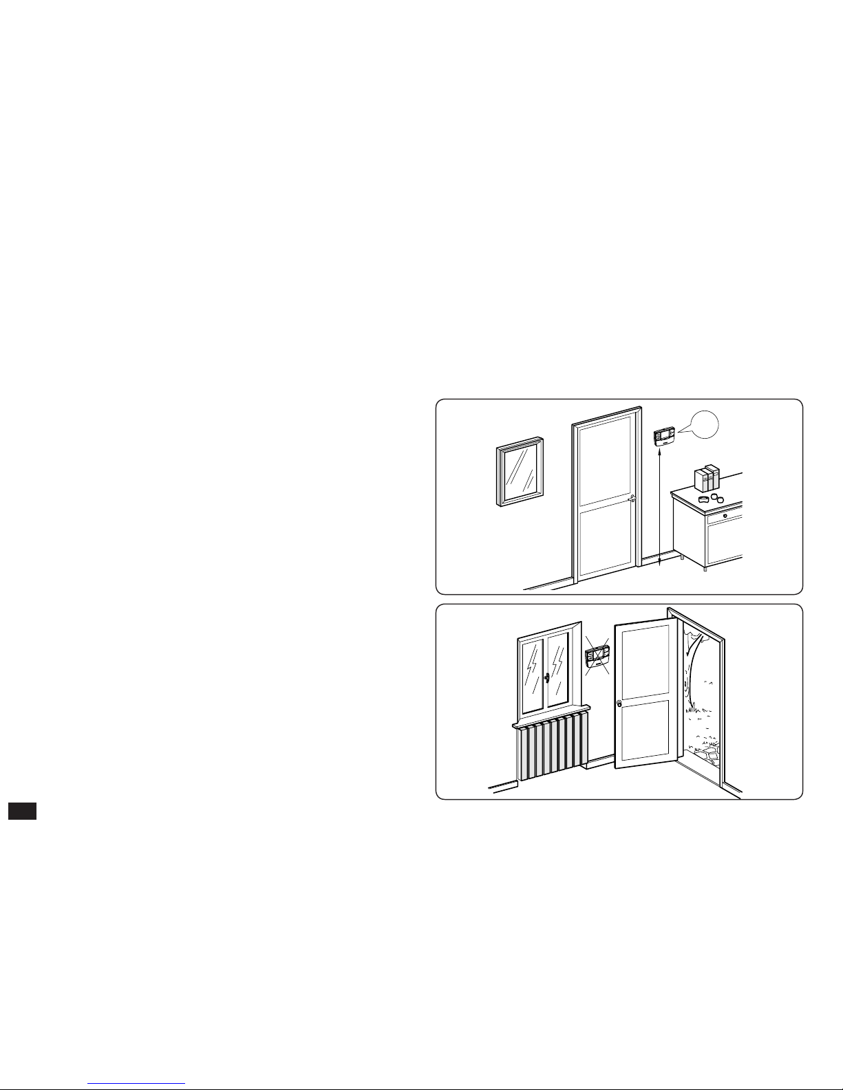
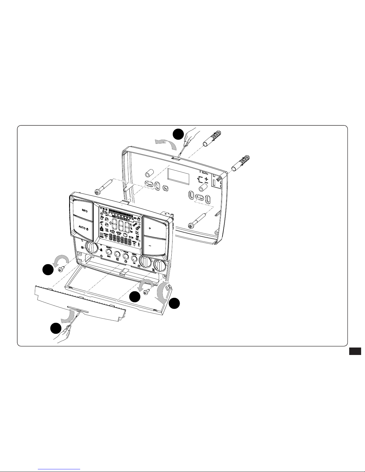
1.2 Installation operations.
1) Separate the xing template from the body of the CAR
V2
remote control using a screwdriver as a lever in the
relevant recess (Fig. 3). Install the CAR V2 remote control
away from heat sources and in a suitable position to detect
the room temperature correctly (Fig. 1 and 2).
Note:
the presence on the rear of the remote control of the
pipe for electric connection cables with the boiler could
recall air from outside the establishment and interfere with
the correct detection of the room temperature (e.g.: boiler
installed outside and use of the suction hood in the kitchen).
Have the job carried out by qualied sta.
2) Install the CAR V2 remote control using the holes made
in the rear of the same directly onto the wall (Fig. 4) or
on a recess box (Fig. 5) using the relative supplied screws.
Fig. 2
Fig. 1
OK
1,5m
NO
Page 7
7
Fig. 3
1
2
3
3
4
Important: the xing screws (action n° 3) on rst
installation are no present on the CAR V2 remote
control, but are supplied in a bag present in the
packaging box.
Once the template is xed to the wall, x the body of
the CAR V2 remote control using the 2 screws.
Page 8
8
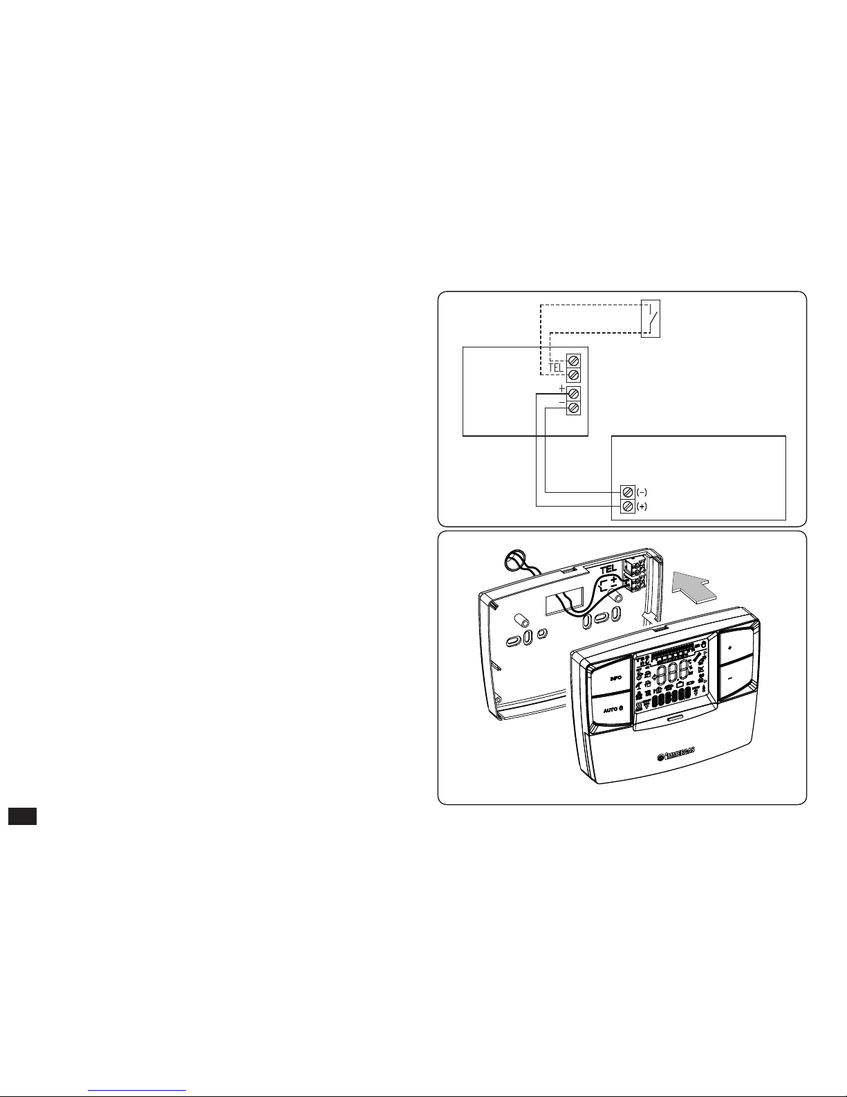
Fig. 5
Fig. 4
3) To make the electrical connections (Fig. 4) do not operate
when the boiler is live. e connection must be made
respecting the polarity of the wires (+ and -). e jumper
on clamps 40 and 41 of the boiler P.C.B. (if present) must
also be eliminated.
Connect the CAR V2 remote control to the boiler clamps
envisioned at communication with the CAR remote control
or, if not present, to the clamps envisioned for the CRD.
Note: refer to the electrical connections stated in the boiler
instruction book.
e connection to the boiler is made using two wires (Fig.
5)with minimum section of 0.50 mm2 and maximum of 1.5
mm2 and with maximum length of 50 metres.
N.B: for correct installation prepare a dedicated line for the
connection of the CAR V2 remote control according to the
Standards in force regarding electrical systems. If this is not
possible interference due to other electric cables could cause
malfunctioning of the CAR V2 remote control itself.
4) Fix the body of the CAR V2 remote control to the support
template, engaging it with pressure and using the two screws
provided (Fig. 3).
5) Aer the boiler has been powered, wait about 30 seconds
before regulation in a way that the communication between
CAR V2 remote control and boiler has established.
Telephone control
(optional)
Boiler
CAR
V2
Page 9
9
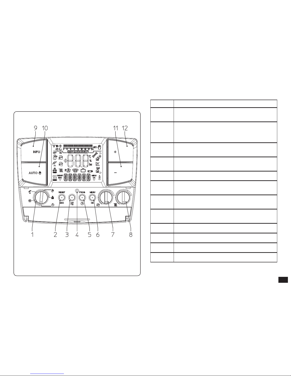
2. DESCRIPTION OF CONTROLS
Fig. 6
Ref. Description
1
Main selector: O, Stand-by/anti-freeze,
Summer, Winter, Cooling
2
“Reset” boiler anomalies/“Esc” escape
parameter or return to previous menu
button (programming mode)
3
Comfort and economy room temperature
setting button
4
Reset button for starting CAR V2 remote
control in event of anomaly of the same.
5 Access button to time, day and timer
6
Access button to the programming/conrm
parameters menu
7
Domestic hot water temperature selector
switch
8
Central heating water temperature selector
switch
9 Information buttons
10 Manual, automatic functioning button
11 Temperature decrease button
12 Temperature increase button
Page 10
10
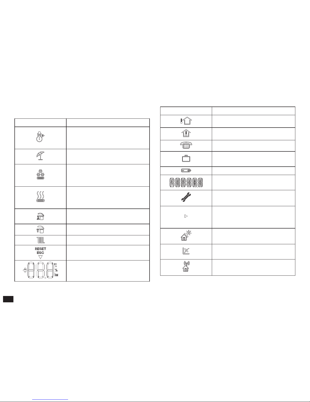
3. DESCRIPTION OF DISPLAY
Symbol Description
winter - DHW heating and
room central heating buttons are
enabled
summer - only the DHW central
heating function is enabled
cooling - the cooling and DHW
central heating function is
enabled
request for room central heating
or cooling by CAR V2 remote
control
aqua celeris active/DHW
comfort in progress
request for DHW in progress
room central heating in progress
description of functioning of the
button (2 g. 6) - Reset, or esc
displays room temperature and
numerical data
Symbol Description
external temperature display
internal temperature display
function activation from remote
functioning with holiday timer
program
not used on this model
description of functioning state
in use
anomaly in boiler presence
symbol
indicates that it is possible to
modify a parameter via the two
buttons (11 and 12 g. 6)
functioning with solar system
active
functioning with external
temperature probe active
functioning in wireless mode
(not used on this model)
Page 11

11
Symbol Description
description of functioning of the
button (6 g. 6) - Menu or Ok
ame presence symbol (only
appears with the connection to
some boiler models)
symbols that identify the
functioning mode in the hourly
programming
time bar that identies the
functioning period at “comfort”
and “economy” temperature
on the basis of the type of
programming (cooling, central
heating, DHW)
functioning with automatic
program
functioning with manual
program
display of days of the week
N.B.: Some icons can assume dierent meanings according
to the context, see the successive paragraphs to identify the
functions activated by the presence of several icons at the
same time.
Page 12

12
4.2 Selection of functioning mode
According to the functioning mode selected, the CAR V2
remote control performs the requests of the user, displaying
the results on the display.
By turning the main selector (ref. 1 g. 6) the following
functions can be selected: Stand-by/Anti-freeze, Summer,
Winter, Cooling.
Note: the room anti-freeze function is active in the following
modes: antifreeze, summer, winter.
• Off mode. The room anti-freeze function is not
guaranteed in this mode (the boiler anti-freeze function
remains active). e CAR V2 remote control is o but
remains powered and therefore the times and programs
remain memorised.
4. STARTUP
4.1 Programming current day and time.
Switch the remote control on by turning the main selector
onto one of the functions available.
Press the button to enter time and current time
mode and press the button to modify the settings.
On entering the programming mode, the time starts to ash.
Modify the hour and minutes by pressing the + / - buttons
and the button to conrm. Select the day of the week
and conrm using the button.
Once regulation has been completed, press the button
to escape the regulation mode.
Fig. 7
Page 13

13
Fig. 8
Fig. 9
• Stand-by/anti-freeze mode ( ). In this mode, the boiler
can only function in the event of anti-freeze request.
In this state, the day, current time, any functioning
anomalies and the room temperature are displayed (g.
8).
• Summer mode ( ). In this mode the boiler is enabled
for producing domestic hot water excluding heating the
environment. e display shows the day and the current
time, the room temperature and hour bar with daily
programming of the DHW timer along with the relative
symbols (g. 9).
• Winter mode ( ). In winter mode the boiler is enabled
for producing domestic hot water and for central heating
the environment. In winter mode the CAR V2 remote
control can function in automatic or manual mode. For
the description of functioning see chapter 6. e display
shows the day and current time, the room temperature
and the hour bar with the daily programming of the
central heating timer along with the relative symbols (g.
10).
Fig. 10
Page 14

14
• Cooling mode ( ). In cooling mode the boiler is enabled
for the production of DHW and to control a chiller (only
for models set-up) for cooling rooms. In "cooling" mode
the CAR V2 remote control can function in automatic or
manual mode. For the description of functioning see
chapter 7. e display shows the day and current time,
the room temperature and the hour bar with the daily
programming of the cooling timer along with the relative
symbols (g. 11).
Fig. 11
Page 15

15
5. SUMMER MODE FUNCTIONS
With the CAR V2 remote control in summer mode ( ), only
the production of DHW is enabled.
The boiler produces hot water according to the DHW
temperature set on the CAR V2 remote control.
5.1 DHW temperature setting.
By turning the selector ( ) it is possible to set the
temperature of the DHW (see g. 12).
By turning in a clockwise direction the temperature
increases and in an anti-clockwise direction it decreases.
e temperature is memorised aer the selector remains
still for a few seconds.
Fig. 12
5.2 DHW timer (for storage tank unit).
If the temperature of the DHW contained in the DHW
storage tank on two distinct levels (comfort and minimum)
is to be regulated, this is possible using the “HW PRG”
function. Regarding this, see the activation mode in the
chapter relative to programming.
The “comfort” temperature corresponds to the value
regulated on the DHW selector. e “minimum” temperature
corresponds to the minimum DHW value envisioned for the
boiler to which the CAR V2 remote control is coupled.
N.B.: if the CAR V2 remote control is functioning at
minimum temperature level it is possible to force the DHW
temperature by acting on the DHW selector.
e CAR V2 remote control is factory set with the DHW
always activated on "comfort" temperature (ON1 00.00
OFF1 24.00).
Page 16

16
6. WINTER MODE FUNCTIONS
With the CAR V2 remote control in winter mode ( ),
the production of DHW and room central heating are
enabled. Two main functioning modes can be selected for
room central heating: automatic or manual. Plus a forced
automatic timed program.
- Manual ( ): the room temperature is kept constant
at the value set by the user every time, according to
requirements.
- Automatic ( ): the room temperature is regulated on
two levels (comfort and economy) during the day via a
program set by the user.
- Forced automatic ( ashing): the room temperature
is modified momentarily with respect to automatic
functioning until the successive passage between comfort
and energy mode of the automatic program set.
6.1 Manual functioning.
By pressing the button, pass alternately from
automatic to manual functioning.
Once manual functioning mode is set, the icon switcheson on the display (g. 13).
To set the desired room temperature, just press the + / buttons and the room temperature set will appear on the
display (g. 14). Just wait a few seconds to conrm the
new value.
In manual functioning mode it is possible to select any
room temperature from +10°C to +35°C, which will be kept
constant until new adjustments or selection of a dierent
functioning mode.
Fig. 14
Fig. 13
Page 17

17
6.2 Automatic functioning.
The CAR V2 allows automatic functioning, in which a
program manages the room temperature during the hours
of the day.
e desired room temperature can be adjusted onto two
independent levels: comfort ( ) and economy ( ) via the
button, whose distribution throughout the day or the
week is managed by hourly programming.
Press the button until the icon switches-on on
the display .
e CAR V2 is factory-set with a standard program stated in
the table that follows. If this should not satisfy requirements,
it is possible to modify it as described in the chapter relative
to programming.
Fig. 15
Note: the system is designed to function on comfort and
economy temperature levels depending on the hour program
set. erefore also during functioning on economy level,
if the room temperature measured is below that set, the
boiler can ignite.
6.3 Forced automatic functioning.
If in automatic functioning mode ( ) the room temperature
is modied by pressing the + / - buttons, the forced automatic
functioning mode is activated (displayed by the switch-on of
the ashing symbol). In this mode, the room temperature
will be regulated to the value set until the next switch-on or
switch-o phase of the automatic program set. e forced
automatic function can be interrupted by simply pressing
the button.
Days
16°C
20°C
Mon - Fri
(Day 1 - 5)
from 23 to 6
from 8 to 11
from 13 to 17
from 6 to 8
from 11 to 13
from 17 to 23
Sat - Sun
(Day 6 -7)
from 23 to 7 from 7 to 23
Fig. 16
Page 18

18
6.4 Boiler ow temperature.
From the winter function mode ( ) it is possible to regulate
the boiler flow temperature. Regulate by rotating the
selector ( ). Clockwise increases the ow temperature,
anti-clockwise decreases it.
N.B.: an excessively low boiler ow temperature adjustment
(below 60°C for traditional systems) may not allow to reach
the desired room temperature.
e boiler ow temperature during normal functioning
is however managed automatically of the CAR V2 remote
control on the basis of the room temperature set. erefore,
it is not certain that the boiler works at the temperature set
but functions at a lower ow temperature, but correct to
obtain the desired room temperature.
If the external temperature probe is present, the flow
temperature will be set according to that described in the
"Special functions" chapter.
6.5 Room anti-freeze function.
The anti-freeze function has maximum priority with
respect to other settings. When the room temperature
drops below 5°C (adjustable, see special functions chapter)
a central heating request is made at minimum of the power
programmed. is situation remains active until there is
a variation in room temperature of 0.6°C equal to 5.6°C
measured in the room where the CAR V2 remote control
is positioned.
6.6 Functioning in winter mode with external
temperature probe.
If an external temperature probe is present, it is possible to
set a ow temperature correction curve depending on the
external temperature. By turning the selector switch ( )
the curve can be regulated from 0 to 9 according to the
graphics g. 23. Regarding this, see the activation mode in
the chapter relative to the special functions.
Page 19

19
7. COOLING MODE FUNCTIONS
With the CAR V2 remote control in cooling mode ( ), the
of DHW heating and room cooling functions are enabled.
Important: this function can only be used with boilers that
an be coupled with a chiller.
Two main functioning modes can be selected: automatic or
manual. Plus a forced automatic timed program.
- Manual ( ): the room temperature is kept constant
at the value set by the user every time, according to
requirements.
- Automatic ( ): the room temperature is regulated on
two levels (comfort and economy) during the day via a
program set by the user.
- Forced automatic ( ashing): the room temperature is
modied momentarily with respect to automatic functioning
until the successive passage between comfort and energy
mode of the automatic program set.
7.1 Manual functioning.
By pressing the button, pass alternately from
automatic to manual functioning.
Once manual functioning mode is set, the icon switches
on on the display (g. 17).
To set the desired room temperature, just press the + / buttons and the room temperature set will appear on the
Fig. 18
Fig. 17
display (g. 18). Just wait a few seconds to conrm the
new value.
In manual functioning mode it is possible to select any
room temperature from +15°C to +40°C, which will be kept
constant until new adjustments or selection of a dierent
functioning mode.
Page 20

20
7.2 Automatic functioning.
The CAR V2 allows automatic functioning, in which a
program manages the room temperature during the hours
of the day.
e desired room temperature can be adjusted onto two
independent levels: comfort ( ) and economy ( ) via the
button, whose distribution throughout the day or the
week is managed by hourly programming.
Press the button until the icon switches-on on
the display .
e CAR V2 is factory-set with a standard program stated in
the table that follows. If this should not satisfy requirements,
it is possible to modify it as described in the chapter relative
to programming.
Note: the system is designed to function on comfort
and economy temperature levels depending on the hour
program set. erefore also during functioning in economy
temperature conditions, if the room temperature measured
is above that set, the chiller can switch-on.
7.3 Forced automatic functioning.
If in automatic functioning mode ( ) the room temperature
is modied by pressing the + / - buttons, the forced automatic
functioning mode is activated (displayed by the switch-on of
the ashing symbol). In this mode, the room temperature
will be regulated to the value set until the next switch-on or
switch-o phase of the automatic program set. e forced
automatic function can be interrupted by simply pressing
the button.
Days
40°C
25°C
Mon - Fri
(Day 1 - 5)
from 23 to 11
from 13 to 17
from 11 to 13
from 17 to 23
Sat - Sun
(Day 6 -7)
from 23 to 13 from 13 to 23
Fig. 20
Fig. 19
Page 21

21
8. INFORMATION
By pressing the button, access a menu that allows to
verify the functioning state of the CAR V2 remote control.
If a determined value is not present “--” will be displayed.
e display of the “info” is subject to the boiler model and
the method of connection of the CAR V2 remote control.
Press the button repeatedly to scroll the list .
To go back to normal functioning mode, press the
button or wait 60 seconds.
e parameters that can be displayed are listed below:
- EXT T: external temperature (the optional external
temperature probe if present).
- HF TMP: Central heating circuit ow temperature.
- HR TMP: central heating circuit return temperature.
- DWIN T: DHW input temperature.
- DHW T: DHW output temperature.
- PAN T: solar collector temperature.
- CH PRS: system pressure, central heating circuit.
- SERVIC: Days remaining before periodic maintenance.
- VER P “x”: “x” identies the type of communication
protocol with the boiler in use:
VER PC = CAR-Bus; VER PI = IMG-Bus.
e display shows the rmware version of the CAR
V2.
remote control
- ZONE: Not used on this model.
N.B.: the sizes displayed depend on the type of boiler to
which the CAR V2 remote control is connected.
Page 22

22
9. PROGRAMMING CAR V2 REMOTE
CONTROL.
Programming of the CAR V2 remote control allows to set/
modify the following parameters:
- comfort and economy temperature levels (dierent for
the “central heating” and “cooling” modes);
- daily/weekly functioning time program (dierent for the
“central heating” and “cooling” and "DHW" modes).
9.1 Setting comfort and economy room
temperature.
e two temperatures are dierent depending whether they
are in "winter" or "cooling" mode.
By pressing the button, the “comfort” (fig. 21) and
“economy” (g. 22) temperatures are displayed alternately.
To regulate both parameters, just press the + / - buttons to
regulate the temperature according to requirements.
To conrm the new temperature, press the button,
to exit without saving the modications, press the
button.
Fig. 21
Fig. 22
Page 23

23
9.2 Programming functioning time.
By pressing the button, it is possible to enter the
time periods programming window for programming the
room temperatures and DHW timer (as well as setting the
current time and day).
By pressing the + / - buttons, the items that can be set in the
menu are displayed alternately.
ere are, in fact, three types of program:
- CH PRG: room central heating program
- HW PRG: DHW heating program
e period in which the DHW temperature is in comfort
will be distinguished by the switch-on of the icon.
N.B.: the function must only be activated in the presence
of a cylinder. e DHW is always active as per standard.
- CHIPRG: room cooling program
By following the points described below, it is possible to
create or modify the time program selected.
1) Press the button, select the program to modify
by pressing the + / - buttons, aer which conrm by pressing
the button.
2) Select the day of group of days by pressing the + / - buttons
and conrm the selection by pressing the button:
- Monday, Tuesday, Wednesday... Sunday (individual day)
- Mon - Fri (from Monday to Friday)
- Sat - Sun (from Saturday to Sunday)
- Mon - Sat (from Monday to Saturday)
- Mon - Sun (from Monday to Sunday)
3) Set the functioning times with comfort and economy
temperature. Within the 24 hours it is possible to dene
a maximum of 4 time periods with Comfort temperature,
each of which is characterised by a switch-on time and a
switch-o time.
e minimum variation of the switch-on and switch-o
time is 30 minutes.
Set the rst functioning period with comfort temperature
(ON 1) indicated at the top and the switch-on time at the
bottom. Press the + / - buttons to modify the switch-on time
and press the button to memorise. At this point, pass
to the next functioning period with comfort temperature
(OFF) indicated at the top and the switch-o time at the
bottom. Press the + / - buttons to modify the switch-o
time and press the button to memorise. When the
Page 24

24
rst phase has been designed, pass automatically to the next
functioning phases at comfort and economy temperature in
order to program. is means repeating the points described
previously up to phase 4.
e sequences of the On and O states must always be
sequential. For example, it is not possible to set “OFF 2” at
13.30 and “ON 3” at 11.00.
Once the day or group of days have been programmed,
proceed in the same way for the remaining days and the
remaining programs.
N.B.: if only 3 switch-on times are used, set the fourth with
switch-on/o time at 24.
N.B. in automatic functioning conditions ( ) the
display will show the 24 hour bar indicating the dierent
time phases with Comfort or Economy temperature
. The presenc e of t h e
hyphen on the time bar corresponds to functioning in
Comfort mode.
Page 25

25
10. DIAGNOSTICS AND ERRORS
10.1 Diagnostics.
The CAR V2 remote control continually controls the
functioning status of the boiler and signals any anomalies,
stating the corresponding error code on the display.
e error codes have meaning depending on the boiler to
which the CAR V2 remote control is connected. erefore,
refer tot he boiler instruction book for a complete list of
error codes and their relative meaning.
In the case of a fault that cannot be reset, contact a qualied
technician (e.g. the Immergas After-Sales Technical
Assistance Service).
“ERR>XX” appears on the display in the event of an error,
where XX stands for the number that identies the error
code as well as the ashing symbol.
As well as the error codes referring to the functioning state
of the boiler, the CAR V2 remote control also checks its own
functioning state, indicating any malfunctions.
Code Description
ERR>CM
Communication error between CAR V2 remote
control and boiler or switch-over phase
between advanced type communication (e.g.
Superior kW) and a normal type
ERR>TP
Error in reading the room temperature or value
measured o scale (below 0°C or over 50°C)
10.2 Reset errors.
In the event of resettable boiler bock, the ashing
icon appears on the display. In this case, by acting on the
relevant button and holding it down for 5 seconds, it is
possible to send a release signal to the boiler that allows
to reset correct boiler functioning within a few seconds.
If normal functioning conditions are set, it goes back to
functioning as previously set.
It is possible to operate up to a maximum of 5 consecutive
reset attempts, aer which an hour must pass before another
5 attempts are available.
10.3 Reset CAR V2 remote control.
Acting on the hole for general rest (ref. 4 g. 6) the CAR V2
remote control hardware can be reset without loosing the
settings made by the user, such as time, date and time prog.
If the CAR V2 remote control original factory set conditions
are to be restored, act as follows.
Press and release the button in the “reset” hole (ref. 4 g. 6)
holding the button down (ref. 2 g. 6).
At this point CAR V2 remote control will be restored with all
factory set data, keeping current time and day.
Page 26

26
11. SPECIAL FUNCTIONS
By pressing the button, a list of options is accessed that
allows to customise functioning of the CAR V2 remote control,
according to the specic necessities.
To scroll the list, press the + / - buttons and press the
button to select the desired function.
11.1 LANGUAGE (language selection).
Allows to set the functioning language of the CAR V2 remote
control. It is possible to select from Italian (ITA as per standard)
and English (ENG).
11.2 REGULT (Management of regulation parameter).
Allows to customise the functioning parameters of the CAR
V2
remote control.
- CH MIN (central heating ow minimum temperature),
allows to regulate the central heating flow minimum
temperature value. Moreover, this value is used to calculate
the curves used for the external probe. Values that are too
high can cause ow temperatures that are too high on average
for room central heating.
- OFFSET (regulation constant), constant that can be regulated
from -15°C to +15°C and which in the presence of the
external probe (optional) modies the set ow temperature
(see g. 23)
set as per standard at 0°C.
TM-MAX/MIN = Selected ow temp. range.
Te = External temperature.
EXTERNAL PROBE
FLOW TEMPERATURE CORRECTION LAWS.
EXTERNAL TEMPERATURE FUNCTION AND THE POSITION OF
THE USER TEMP. ADJUSTMENT CENTRAL HEATING.
Fig. 23
N.B.: if the self-learning function is enabled, the Oset value
could be modied automatically.
- BUILD (dimension and building inertia), adjustable from
1 to 20, as per standard set on 10. It establishes the reaction
speed of the system depending on the type of system present.
For example:
Value System type
5 system with little heat inertia
10
system with normal dimensions with
radiators
Position of the central heating temperature
user adjustment central heating temp.
Page 27

27
20
system with a lot of heat inertia (e.g. oorstanding system)
- AUTO A (self-learning), defines the activation of selflearning, as per standard set at OFF. is function allows
the CAR V2 remote control to vary the oset, adapting it
to the room in which it is installed.
11.3 HOLIDY (holiday program).
From winter functioning mode it is possible to dene a number
of days (from 1 to 99) during which the system deactivates
both the hot water heating function and the room central
heating function.
e value is decreased every midnight in the day change. At the
end of the days set (the meter reaches 0) the previously active
functions are restored. e activation of the holiday function
is indicated by the ashing of the icon and the count of the
days remaining.
The holiday function can be deactivated by pressing the
button.
In the event of remote activation from telephone control, the
boiler is activated with the settings of the telephone control,
omitting the Holiday program.
N.B.: the room anti-freeze function is however guaranteed
also in holiday mode.
11.4 LEGION (anti-legionella function ).
Allows to activate the Anti-legionella function that takes
the temperature of the cylinder to maximum allowed for 20
minutes. It is possible to select between the once a day at 2 in
the night (ON 24H), every 7 days on Monday at 2 in the night
(ON 7 DAYS) or deactivate it (OFF standard function).
N.B.: the function must only be activated in presence of boiler
and eventually a thermostatic valve must be installed at the
DHW output to prevent burns.
11.5 REMOTE (telephone control).
Allows to set the functioning of the CAR V2 remote control
in a way that, in the event of remote activation, it functions
with the automatic time program if set at AUTO. Vice versa,
it functions at continuous comfort temperature (without time
program) if set at ON.
In the event of activation, it displays the ashing ( ) icon.
11.6 CODE.
To use this function, see the “Functions protected by code”
chapter.
Page 28

28
12. FUNCTIONS PROTECTED BY CODE
CODE.
They are advanced character settings (reserved for an
enabled technician), a four character code must be entered
in order to access them (code: 1122).
Press the button and scroll the options present
until “CODE” appears, press the button and insert the
code by selecting the characters using the + / - buttons and
conrming them by pressing the button.
Aer which it is possible to display and modify the following
functions.
12.1 AMB (room probe - On / O or modulating
functioning mode).
Allows to activate or deactivate the room probe present in
the CAR V2 remote control. On the basis of the parameter
setting, it will be possible to regulate the following options:
- AMB: ON (standard value); it is possible to select a cor-
rection factor of the room probe reading and change the
modulating function.
- AMB CR: room robe reading correction, the room
probe range reading can be corrected within a range
of + 3.0 - 3.0°C.
- MODUL (On / O or Modulating functioning):
allows setting functioning of the CAR V2 remote
control On/O or Modulating. Set at ON, the ow
temperature will be varied depending on the room
temperature set. Set at OFF, the ow temperature will
be kept constant until the desired room temperature
is reached. (Setting to be made on systems with zones
control unit).
N.B.: if an external temperature probe is present, the
ow temperature will be set depending on the relative
functioning curve.
- AMB: OFF, the system will not function, regulating
the room temperature but only depending on the time
program set. In this case the room anti-freeze function
is not assured.
12.2 REDUCT (functioning in reduced mode).
if activated with AMB parameter at “OFF”, it denes how the
ow temperature must be in Economy period.
- REDUCT OFF: in functioning periods in Economy mode,
the boiler is switched-o.
- REDUCT ON: in functioning periods in Economy mode,
it reduces the ow temperature by an amount equal to
that set (adjustable from -1°C to -40°C).
Page 29

29
12.3 FRO PR (anti-freeze level).
Allows to set the room temperature for activation of the
anti-freeze function. Can be regulated from 0°C to 10°C
and is set at 5°C as standard.
12.4 ZONE (function not present on this model).
12.5 SERVIC (programmed maintenance).
Sets the period for periodic maintenance (can be set from 6
to 24 months or “O ”). When the period has been set, the
telephone number that the user must contact to perform
periodic maintenance is set.
13. DISABLING
THE CHRONOTHERMOSTAT.
If CARV2 must be used as a boiler control only (simple remote
control function), proceed as follows:
- deactivate the room probe (para. 12.1):
- exclude the 4 time periods of the “PR RIS” in the “Mon
- Sun” group of days, setting the On and O of all 4 time
periods (on1, o1, on2, o2, on3, o3, on4, o4) to 24.00;
- press the AUTO button to set the automatic mode.
N.B.: for the boiler to work in heating mode, the room
thermostat contacts (40-41) on the boiler board must
be closed.
Page 30

30
14. TECHNICAL CHARACTERISTICS
• Dimensions (LxHxD): ..................................................................................................................................142 x 103 x 31 (mm)
• Power Supply: ................................................................................................ 24V nominal via twin-wire communication Bus
• CAR_BUS protocol power supply voltage: .............................................................................................................. 24 ÷ 35 Vdc.
• CAR_BUS protocol maximum input: ............................................................................................................. 10 mA - 350 mW.
• IMG_BUS protocol maximum power supply voltage: ....................................................................................................18 Vdc.
• IMG_BUS protocol maximum input: ............................................................................................................. 23 mA - 250 mW.
• Functioning room temperature: .................................................................................................................................... 0 - +40°C
• Warehouse temperature: ..............................................................................................................................................-10 - +50°C
• Protection rating according to EN 60730: .................................................................................................................................. II
• Protection rating according to EN 60529: ............................................................................................................................IP 20
• Connection technique: ........................................................................................................................................2 polarised wires
• Load reserve time: ......................................................................... 8 hours for hourly count (with at least 2 hours of charge)
• Connection cable max. length: .......................................50 m (with cable of 2x0.75mm2) (0.5 ÷mm2 min - 1.5 mm2 max)
• Precision indication room temp.: .....................................................................................................................+/- 0.5°C a 25°C*
• NTC room temp. sensor: ............................................................................................................................................50 k at 25°C
• Clock indication diversion ........................................................................................................................... +/- 15 minutes/year
* = the indication of the room temperature can be aected by the point of installation of the CAR V2 remote control (e.g.
hot wall, cold wall, height from the ground, etc.)
Page 31

31
15. FACTORY SETTING
• Functioning state ........................................................................................................................................................................O
• Functioning program ......................................................................................................................................................... Manual
• Central heating Comfort temperature ...............................................................................................................................20.0°C
• Central heating Economy temperature ..............................................................................................................................16.0°C
• Cooling Comfort temperature ............................................................................................................................................25.0°C
• Cooling Economy temperature ...........................................................................................................................................40.0°C
• Room temperature in manual .............................................................................................................................................20.0°C
• Anti-freeze ...............................................................................................................................................................................5.0°C
• Holiday Program..................................................................................................................................................HOLIDY = OFF
• Oset ....................................................................................................................................................................... OFFSET = 0°C
• Building inertia dimension ....................................................................................................................................... BUILD = 10
• Self-learning .........................................................................................................................................................AUTO A = OFF
• Room Probe ..................................................................................................................................................................AMB = ON
• Reading Correction ........................................................................................................................................... AMB CR = 0.0°C
• Reduction ............................................................................................................................................................. REDUCT = OFF
• Modulation .............................................................................................................................................................MODUL = ON
• Telephone control ................................................................................................................................................ REMOTE = ON
• Antilegionella: ......................................................................................................................................................LEGION = OFF
• Language: .................................................................................................................................................... LANG = ITA (Italian)
Page 32

Immergas S.p.A.
42041 Brescello (RE) Italy
Tel. 0522 689011
CUSTOMER SERVICE
Free Phone 800 - 306 306
immergas.com
Code 1.031170 - Rev. 15.033917/003 - 10/11
 Loading...