

Page 1
Instructions and warnings
Installer
User
Maintenance technician
IE
CAESAR ECO 17
Wall-hung instantaneous
water heaters
with sealed chamber (type C) and
fan assisted
or
open chamber (type B) and
fan assisted
*1.043165ENG*
*1.043165ENG*
Page 2

Page 3

Dear Customer,
Congratulations for having chosen a top-quality Immergas product, able to assure well-being and safety for a long period of time. As an Immergas Customer,
you can also count on a qualied aer-sales service, prepared and updated to guarantee constant eciency of your water heater. Read the following pages
carefully: you will be able to draw useful tips on the proper use of the device, compliance with which will conrm your satisfaction with the Immergas product.
For assistance and scheduled maintenance contact Authorised Aer-Sales centres: they have original spare parts and are specically trained directly by the
manufacturer.
General warnings
All Immergas products are protected with suitable transport packaging.
e material must be stored in a dry place protected from the weather.
e instruction booklet is an integral and essential part of the product and must be given to the new user in the case of transfer or succession of ownership.
It must be stored with care and consulted carefully, as all of the warnings provide important safety indications for installation, use and maintenance stages.
is instructions manual provides technical information for installing Immergas water heaters. As for the other issues related to water heater installation (e.g.
safety in the work site, environment protection, injury prevention), it is necessary to comply with the provisions of the regulations in force and the principles
of good practice.
Installation and maintenance must be performed in compliance with the regulations in force, according to the manufacturer's instructions and by professionally
qualied sta, intended as sta with specic technical skills in the system sector, as envisioned by the Law.
Improper installation or assembly of the Immergas appliance and/or components, accessories, kits and devices can cause unexpected problems for people,
animals and objects. Read the instructions provided with the product carefully to ensure proper installation.
Maintenance must be carried out by skilled technical sta. e Authorised Aer-Sales Service represents a guarantee in terms of qualications and professionalism.
e appliance must only be destined for the use for which it has been expressly declared. Any other use will be considered improper and therefore potentially
dangerous.
If errors occur during installation, operation and maintenance, due to non-compliance with technical laws in force, standards or instructions contained in
this book (or however supplied by the manufacturer), the manufacturer is excluded from any contractual and extra-contractual liability for any damage and
the appliance warranty is invalidated.
e company S.p.A., with registered oce in via Cisa Ligure 95 42041 Brescello (RE), declares that the design, manufacturing and aer-sales assistance
processes comply with the requirements of standard UNI EN ISO 9001:2015.
For further details on the product CE marking, request a copy of the Declaration of Conformity from the manufacturer, specifying the appliance model
and the language of the country.
e manufacturer declines all liability due to printing or transcription errors, reserving the right to make any modications to its technical and commercial
documents without forewarning.
Page 4

INDEX
USER page INSTALLER page MAINTENANCE TECHNICIAN page
1 Water heater installation .........................5
1.1 Installation recommendations. .............. 5
1.2 Main dimensions. ....................................6
1.3 Antifreeze protection. .............................6
1.4 Gas connection. ....................................... 6
1.5 Hydraulic connection..............................7
1.6 Electrical connection. ............................. 7
1.7 Immergas ue systems. ...........................8
1.8 Tables of Resistance Factors and
Equivalent Lengths. .................................9
1.9 Concentric horizontal kit installation. 10
1.10 Concentric vertical kit installation. .....10
1.11 Separator kit installation. ......................11
1.12 Ducting of ues or technical slots. ......12
1.13 Installation of boiler type B with open
chamber and fan assisted (optional). .. 12
1.14 Flue exhaust to ue/chimney. .............. 12
1.15 Flues, chimneys and chimney pots. ....12
1.16 Gas system start-up. ..............................12
1.17 Water heater start up (ignition). ..........12
1.18 Procedure for rst ignition,
preparation to use the appliance. ......... 13
1.19 Kits available on request. ...................... 13
1.20 Water heater components. .................... 14
2 Instructions for use and maintenance 15
2.1 Cleaning and maintenance. ..................15
2.2 General warnings. .................................. 15
2.3 Quick appliance operation guide. ........15
2.4 Control panel. ........................................16
2.5 Faults and screen displays.....................16
2.6 Emptying the water heater. ................... 17
2.7 Anti-freeze protection (optional). .......17
2.8 Cleaning the case. .................................. 17
2.9 Decommissioning. .................................17
2.10 Gas system not used for periods
over 12 months. .....................................17
3 Check and maintenance .......................18
3.1 Hydraulic diagram. ................................18
3.2 Wiring diagram. .....................................19
3.3 Service Menu. .........................................20
3.4 Possible problems and their causes. ....22
3.5 Converting the water heater
to other types of gas...............................22
3.6 Solar panels coupling function. ...........23
3.7 Check the network pressure
(minimum power supply pressure -
only with appliances operating
with methane). .......................................24
3.8 Yearly appliance check
and maintenance. ...................................24
3.9 Casing removal. .....................................25
3.10 Combustion parameters. ......................26
3.11 Technical data. .......................................26
3.12 Product che (in compliance
with Regulation 812/2013). ..................27
3.13 Parameters for lling
in the package che. ..............................28
Page 5
5 cm 5 cm
WATER HEATER
1
INSTALLATION
1.1 INSTALLATION
RECOMMENDATIONS.
e water heater has been designed for wall
installation only, for the production of domestic
hot water in domestic and similar uses.
e place of installation of the appliance and
relative Immergas accessories must have suitable
features (technical and structural), such as to allow for (always in safe, ecient and comfortable
conditions):
- installation (according to the provisions of
technical legislation and technical regulations);
- maintenance operations (including scheduled,
periodic, routine and special maintenance);
- removal (outdoors in the place for loading and
transporting the appliances and components)
as well as their eventual replacement with
appliances and/or equivalent components.
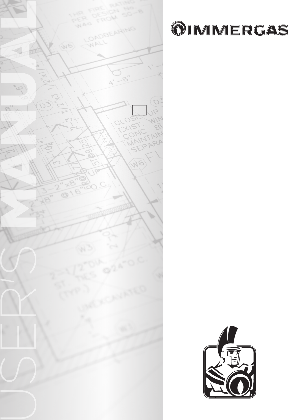
In case of wall installation the wall surface must
be smooth, without any protrusions or recesses
enabling access to the rear part. ey are not designed to be installed on plinths or oors (Fig. 1).
By varying the type of installation the classication of the water heater also varies, precisely:
- Type B water heater22 if installed using the
relevant terminal for air intake directly from
the room in which the water heater has been
installed.
- Type C water heater if installed using concen-
tric pipes or other types of pipes envisioned for
the sealed chamber water heaters for intake of
air and expulsion of fumes.
Only professionally qualified companies are
authorised to install Immergas gas appliances.
Installation must be carried out according to
regulation standards, current legislation and in
compliance with local technical regulations and
the required technical procedures.
Attention: it is forbidden to install water heaters
removed from other systems. e manufacturer
declines all liability in the event of damage caused
by water heaters removed from other systems or
for any non-conformities with such equipment.
Attention: before commissioning the water
heater, if it is operated with LPG, make sure
parameters 2 and 13 on page 21 have been set
correctly.
Installation of the water heater when powered
by LPG must comply with the rules regarding
gases with a greater density than air (remember,
as an example, that it is prohibited to install systems powered with the above-mentioned gas in
rooms where the oor is at a lower quota that the
average external country one). Before installing
the appliance, ensure it has been delivered in
perfect condition; if in doubt, contact the supplier
immediately.
Packing materials (staples, nails, plastic bags,
polystyrene foam, etc.) constitute a hazard and
must be kept out of the reach of children. If the
appliance is installed inside or between cabinets,
ensure sufficient space for normal servicing;
therefore, leave clearance of at least 5 cm between
the water heater casing and the vertical sides of
the cabinet. Leave adequate space above and
below the water heater for possible water and
ue removal connections (Ref. Fig. 2).
Keep all ammable objects away from the appliance (paper, rags, plastic, polystyrene, etc.).
It is recommended not to position household
appliances under the water heater because they
could undergo damage in the case of leaks from
the hydraulic ttings. If this is not the case, the
manufacturer cannot be considered liable for
any damage caused to the household appliances.
For the aforementioned reasons, we recommend
not placing furnishings, furniture, etc. under the
water heater.
In the event of malfunctions, faults or incorrect
operation, turn the appliance o and contact an
authorised company (e.g. the Authorised Technical Assistance centre, which has specically
trained sta and original spare parts). Do not
attempt to modify or repair the appliance alone.
Failure to comply with the above implies personal
responsibility and invalidates the warranty.
• Installation Standards:
- this water heater was designed and built for
installation inside buildings.
- Installation of gas appliances, ue exhaust
pipes and combustion air intake pipes is
forbidden in places with a re risk (for example: garages, closed parking stalls), and
in potentially dangerous places.
- Installation on the vertical projection of
cooking hobs is forbidden.
- Installation is forbidden in places/rooms
that constitute public areas of apartment
buildings, internal stairways or other escape
routes (e.g. oor landings, entrance halls,
etc.).
- Installation is also forbidden in places/rooms
that constitute public areas of apartment
buildings such as cellars, entrance halls, attics,
los, etc., unless otherwise provided for by
local regulations in force.
- It is forbidden to install the water heater
inside a closed recessed frame (e.g. Omni
Container).
- e appliance was designed to be installed in
indoor and protected places.
- It must also be installed in an environment
in which the temperature cannot fall below
0°C. It must not be exposed to atmospheric
agents.
If the water heater is installed in a place whose
temperature drops below 0°C, it is compulsory
to use the antifreeze accessory that provides for
adequate protection down to -15°C.
YES
- It is prohibited to obstruct the air intake
and aeration grids where the appliance is
installed.
Attention: wall mounting of the water heater
must guarantee stable and ecient support for
the generator.
e fastening plugs (standard supply) are only to
be used to x the water heater to the wall; they
only ensure adequate support if inserted correctly
(according to technical standards) in walls made
of solid or semi-hollow brick or block. In the
case of walls made from hollow brick or block,
partitions with limited static properties, or in any
case walls other than those indicated, a static test
must be carried out to ensure adequate mount.
ese appliances are used to heat water to below
boiling temperature in atmospheric pressure.
ey must be connected to a DHW distribution
network suited to their performance and power.
NO
1
INSTALLERUSER
MAINTENANCE TECHNICIAN
20 cm
2
5
Page 6
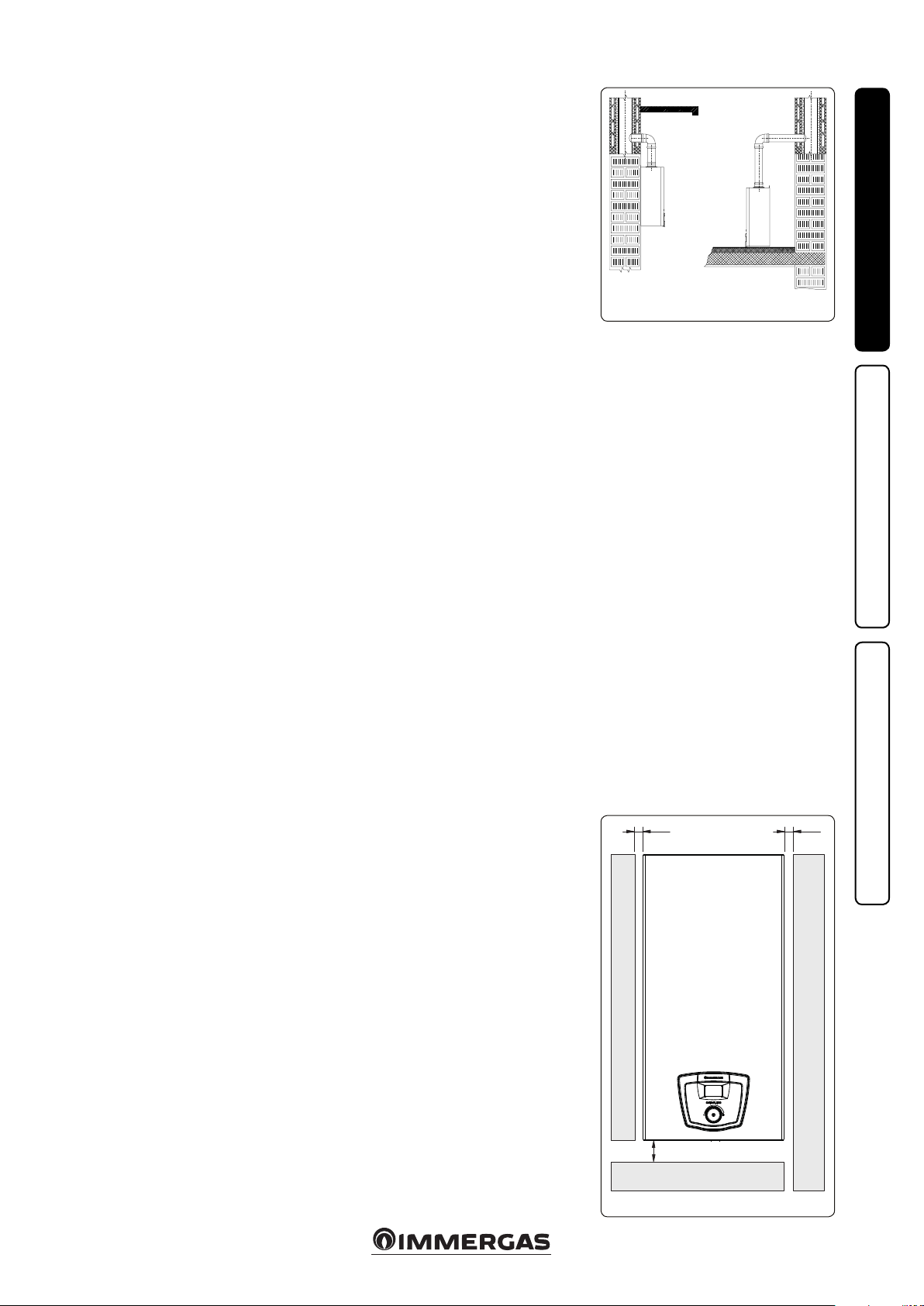
1.2 MAIN DIMENSIONS.
Caesar Eco 17
INSTALLERUSER
A
A/S
A A/S
CONNECTIONS
GAS DOMESTIC HOT WATER
G AC AF
3/4” 1/2” 1/2”
Key:
A
A/S
AC - Domestic hot water outlet
AF - Domestic hot water inlet
G - Gas supply
V - Electrical connection
A - Intake
S - Exhaust
A/S - Intake/Exhaust
3
1.3 ANTIFREEZE PROTECTION.
Minimum temperature. If the water heater
is installed in a place where the temperature
falls below 0°C, the connection pipes must be
insulated and, in the event there is no gas (or
the water heater goes into no ignition block), the
appliance can freeze.
To prevent the risk of freezing follow the instructions below:
- Protect the domestic hot water circuit against
freezing by using an accessory that is supplied
on request (anti-freeze kit) comprising two
electric heating elements, the relevant cables
and a control thermostat (carefully read and
MAINTENANCE TECHNICIAN
follow the installation instructions contained
in the accessory kit pack).
Water heater anti-freeze protection is thus ensured
only if:
- the water heater is correctly connected to electricity power supply circuits;
- the main switch is on;
- the antifreeze kit is installed correctly;
- the connection pipes are insulated.
In these conditions the water heater is protected
against freezing to temperature of -15°C.
e warranty does not cover damage due to interruption of the electrical power supply and failure
to comply with that stated on the previous page.
1.4 GAS CONNECTION.
Our water heaters are designed to operate with
methane gas (G20) and LPG. Supply pipes must
be the same as or larger than the 3/4”G water
heater tting. Before connecting the gas line,
carefully clean inside all the fuel feed system
pipes to remove any residue that could impair
water heater eciency. Also make sure the gas
corresponds to that for which the water heater
is prepared (see water heater data-plate). If
dierent, the water heater must be converted
for operation with the other type of gas (see
converting appliance for other gas types). It is
also important to check the dynamic pressure
of the mains (methane or LPG) used to supply
the water heater, which must comply with EN
437 and its attachment, as insucient levels may
reduce generator output and cause discomfort
to the user.
Ensure correct gas cock connection. e gas
supply pipe must be suitably dimensioned
according to current regulations in order to
guarantee correct gas ow rate to the burner even
in conditions of maximum generator output and
to guarantee appliance eciency (technical specications). e coupling system must conform to
standards in force.
Fuel gas quality. e appliance was designed to
operate with combustible gas free of impurities;
otherwise it is advisable to fit special filters
upstream of the appliance to restore the purity
of the fuel.
Storage tanks (in case of supply from LPG
depot).
- New LPG storage tanks may contain residual
inert gases (nitrogen) that degrade the mixture
delivered to the appliance casing functioning
anomalies.
- Due to the composition of the LPG mixture,
layering of the mixture components may occur
during the period of storage in the tanks. is
can cause a variation in the caloric value of
the mixture delivered to the appliance, with
subsequent change in its performance.
6
Page 7
1.5 HYDRAULIC CONNECTION.
Attention: before connecting the water heater
and so as not to make the warranty null and void
on the DHW heat exchanger, wash the system
thoroughly (piping, etc.) in a way to remove
any residue that could compromise the good
functioning of the water heater.
Water connections must be made in a rational
way using the couplings on the water heater
template.
Attention: to preserve the duration and features
of appliance eciency, in the presence of water
whose features can lead to the deposit of lime
scale, it is necessary to install the “polyphosphate
dispenser” kit.
1.6 ELECTRICAL CONNECTION.
e “Caesar Eco” water heater has an IPX5D protection rating for the entire appliance. Electrical
safety of the appliance is reached only when it
is correctly connected to an ecient earthing
system as specied by current safety standards.
Attention: the manufacturer declines any
responsibility for damage or physical injury
caused by failure to connect the water heater to
an ecient earth system or failure to comply with
the technical reference standards.
Also ensure that the electrical installation corresponds to maximum absorbed power specications as shown on the water heater data-plate.
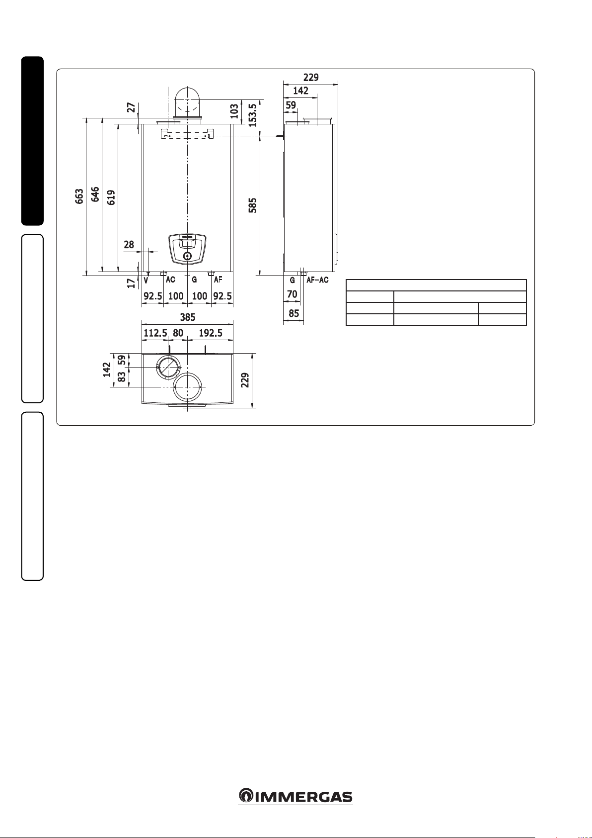
Water heaters are supplied complete with an
“X” type power cable without plug. e power
cable must be connected to a 230V ±10% / 50Hz
mains, respecting L-N polarity and the earthing
connection ; this network must have a multi-pole circuit breaker with Class III overvoltage
category. If the power supply cable is damaged, it
must be replaced by a special cable or assembly,
which are only available from the manufacturer
or its Aer-sales Service. It is recommended to
contact a qualied company (e.g. the Authorised
After-Sales Technical Assistance Service) for
replacement to avoid a hazard. e power cable
must be laid as shown (Fig. 4).
If the network fuse on the connection terminal
block needs replacing, this must also be done by
qualied personnel: use a 3.15 A fast fuse. For
the main power supply to the appliance, never
use adapters, multiple sockets or extension leads.
N.B.: all water heater pipes must never be used
to earth the electric or telephone lines. Ensure
elimination of this risk before making the water
heater electrical connections.
INSTALLERUSER
Power cable
4
MAINTENANCE TECHNICIAN
7
Page 8
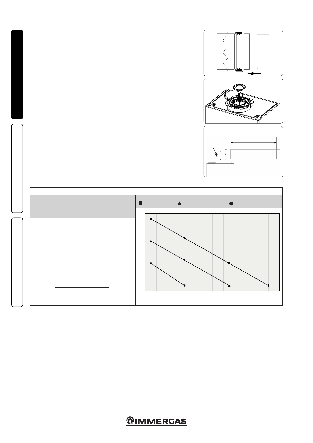
1.7 IMMERGAS FLUE SYSTEMS.
1
1
14
0 2 4 6 8 10 12 14 16 18 20 22 24
Immergas supplies various solutions separately
from the water heaters regarding the installation of
air intake terminals and ue extraction, which are
fundamental for water heater operation.
Attention: e water heater must only be installed
together with an original Immergas air intake and
ue gas exhaust system, in compliance with the
standards in force. is system can be identied
by an identication mark and special distinctive
marking bearing the note "not for condensing
boilers".
INSTALLERUSER
e ue exhaust pipes must not be in contact with
or be near to ammable materials. Moreover, they
must not pass through buildings or walls made of
ammable material.
• Positioning of double lip seals. For correct posi-
tioning of lip seals on elbows and extensions, follow
the assembly direction (Fig. 5).
• Coupling extension pipes and concentric
elbows. To install snap-fit extensions with
other elements of the ue extraction elements
assembly, follows:
Fit the concentric pipe or elbow with the male
side (smooth) on the female section (with lip
seal) to the end stop on the previously installed
element. is will ensure sealing and joining of
the elements correctly.
Attention: if the exhaust terminal and/or
concentric extension pipe needs shortening,
consider that the internal duct must always
protrude by 5 mm with respect to the external
duct.
• N.B.: for safety purposes, do not obstruct the
water heater intake-exhaust terminal, even
temporarily.
• N.B.: when installing horizontal pipes, a min-
imum inclination towards the water either of
3% must be maintained and a section clamp
with plug must be installed every 3 metres.
• Diaphragm installation. For proper water
heater operation, a diaphragm must be installed
on the outlet of the sealed chamber and before
the exhaust pipe (Fig. 6).
N.B.: the diaphragm is supplied as per standard
with the water heater.
e head loss of the
90° bend coming
out from the appliance must NOT be
calculated
Duct length/metres
Maximum completed length
5
6
7
duct length [m]
type of exhaust
B22
Type C
d.60/100
horizontal
Type C
d.60/100
vertical
Type C
d.80/80
MAINTENANCE TECHNICIAN
Attention: if installation requires signicant ue exhaust sections, it is necessary to consider the formation of condensate and thus use the “blue series”
insulated type of ue.
excluding the 90°
outlet bend from the
appliance.
Ref. g. 7
up to 4 46
from 8 to 12 none
up to 1 46
from 1.6 to 3.2 none
up to 2 46
from 2.6 to 4.2 none
3+3 46
from 3+3 to 6+6 48
from 6+6 to 9+9 none
ue gas
diaphragm
[d. mm]
head loss of
every additional
bend
45° 90°
1.3 m 1.8 mfrom 4 to 8 48
1 m 1.4 mfrom 1 to 1.6 48
1 m 1.4 mfrom 2 to 2.6 48
1.3 m 1.8 m
without diaphragm - with a 48 diam. diaphragm - with a 46 diam. diaphragm
With separate ducts having dierent lengths
2
0
8
6
4
Length of ue exhaust pipe (m)
2
0
Air intake pipe length (m)
Caesar Eco 17
8
Page 9
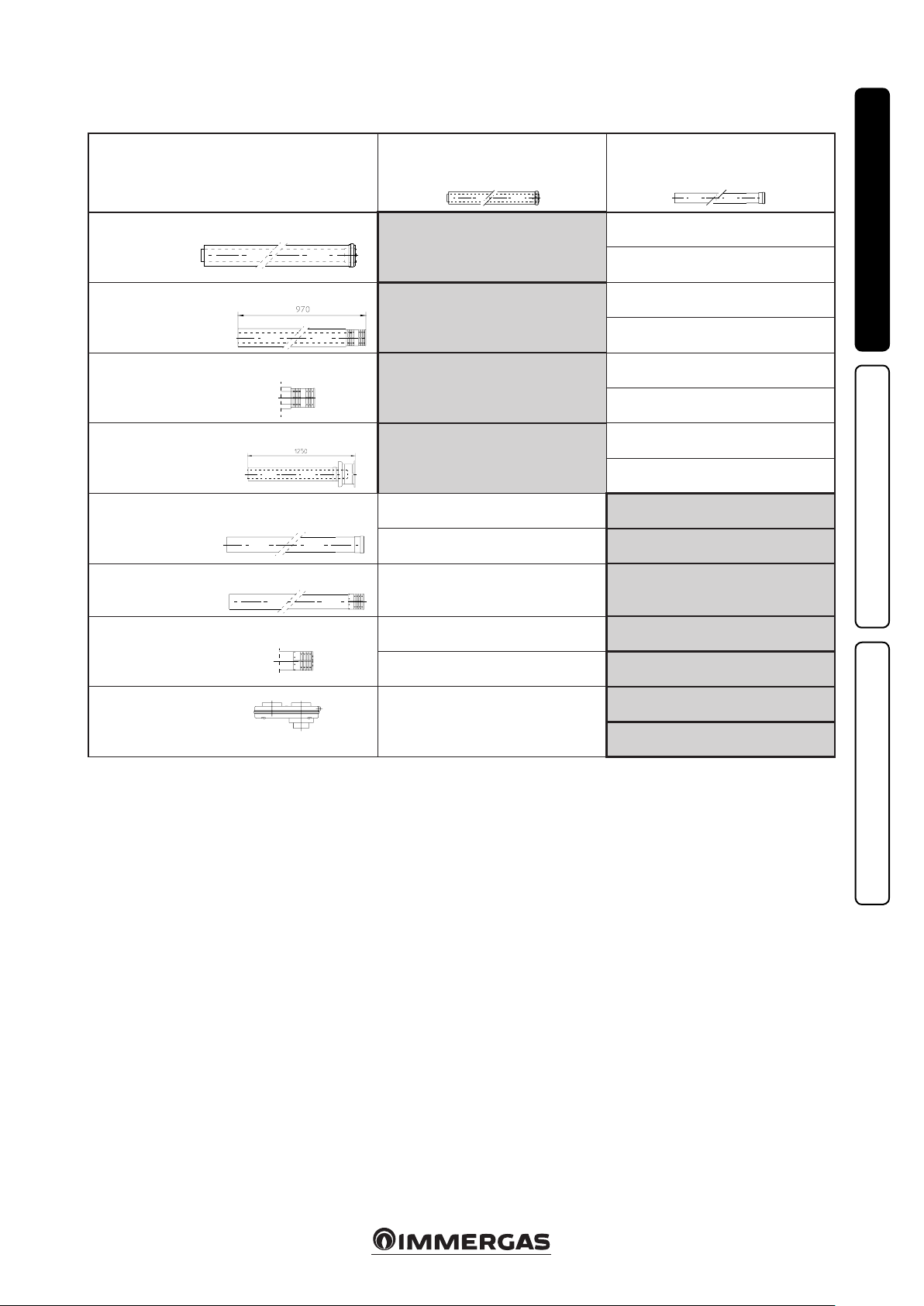
1.8 TABLES OF RESISTANCE FACTORS
AND EQUIVALENT LENGTHS.
TYPE OF DUCT
Concentric pipe Ø 60/100 m 1
Terminal complete with intake-exhaust
horizontal concentric Ø 60/100
Intake-exhaust terminal
horizontal concentric Ø 60/100
Intake-exhaust terminal
vertical concentric Ø 60/100
Pipe Ø 80 m 1 (with and without insulation)
Complete intake terminal Ø 80 m 1
(with or without insulation)
Length
in m of concentric pipe
Ø 60/100
m 1
m 2.8
m 1.9
m 2.5
m 0.1 Intake m 1.0
m 0.2 Exhaust m 1.0
m 0.3 Intake m 2.2
Length
in metres
of pipe
Ø 80
Intake m 7.1
Exhaust m 5.5
Intake m 20
Exhaust m 15
Intake m 14
Exhaust m 10.6
Intake m 18
Exhaust 14
INSTALLERUSER
Intake terminal Ø 80
Exhaust terminal Ø 80
Split parallel Ø 80
from Ø 60/100 to Ø 80/80
m 0.2 Intake m 1.3
m 0.1 Exhaust m 0.8
Intake m 3.8
m 0.5
Exhaust m 2.9
MAINTENANCE TECHNICIAN
9
Page 10
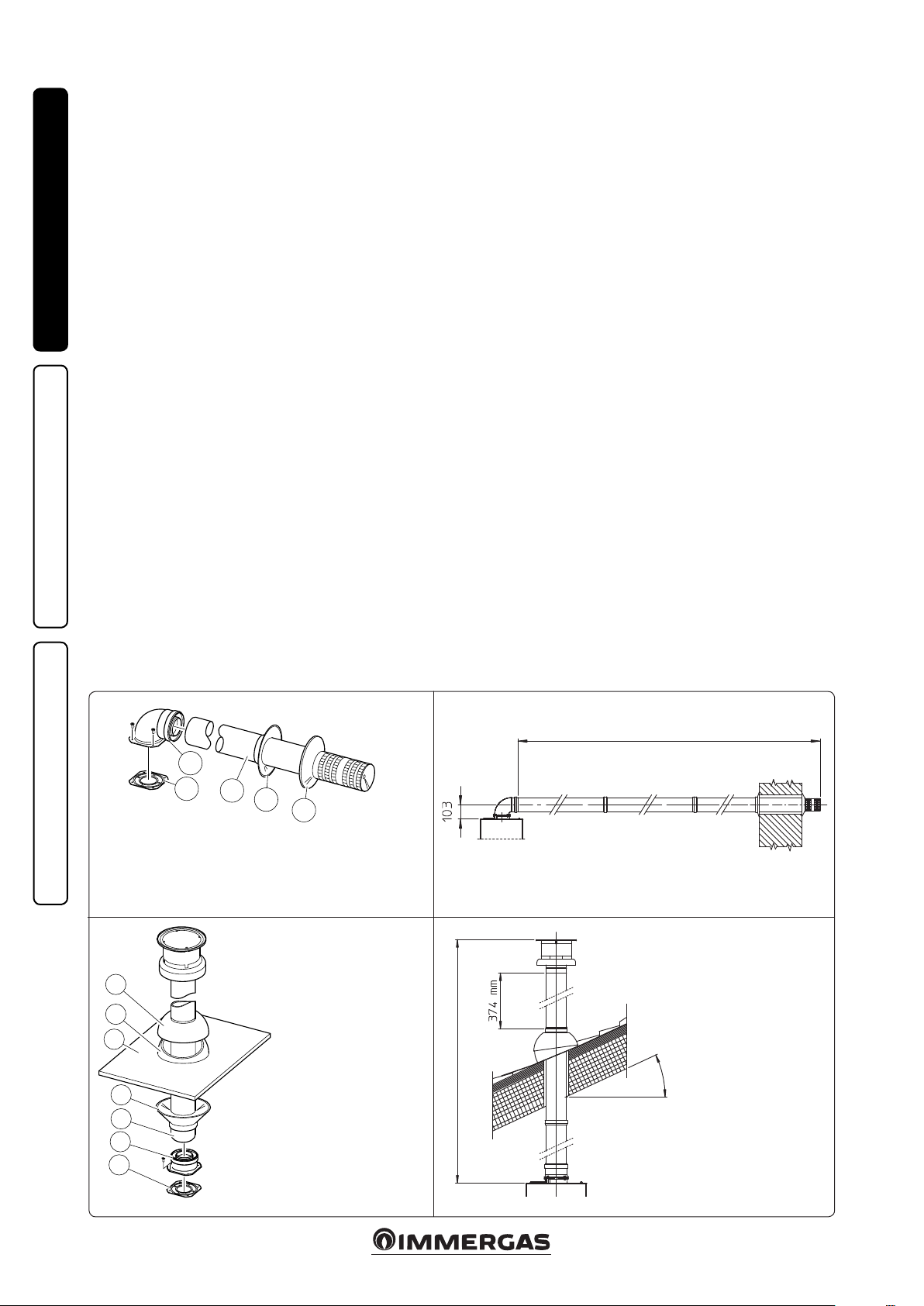
1.9 CONCENTRIC HORIZONTAL KIT
INSTALLATION.
Type C configuration, sealed chamber and
fan assisted.
Installation of this terminal is governed by current technical regulations.
is terminal is connected directly to the outside
of the building for air intake and ue exhaust. e
horizontal kit can be installed with the rear, right
side, le side or front outlet.
• External grid. e Ø 60/100 intake/exhaust
INSTALLERUSER
terminal, if properly installed, is pleasant to
look at on the outside of the building. Make
sure that the external silicone wall sealing plate
is properly inserted in the wall.
Horizontal intake-exhaust kit Ø 60/100. Kit
assembly (Fig. 8): install the bend with ange
(2) onto the central hole of the water heater
inserting the gasket (1) and tighten using the
screws included in the kit. Couple the concentric
terminal pipe Ø 60/100 (3) with the male end
(smooth) into the female end (with lip seals)
of the bend (2) up to the stop, making sure that
the internal and external wall sealing plate have
been tted, this will ensure sealing and joining
of the kit elements.
• Extensions for Ø 60/100 horizontal kit (Fig. 9).
e kit with this conguration can be extended
up to a max. horizontal length of 3.2 m includ-
ing the terminal with grid and excluding the
concentric bend leaving the water heater. In this
case the special extensions must be requested.
1.10 CONCENTRIC VERTICAL KIT
INSTALLATION.
Type C configuration, sealed chamber and
fan assisted.
Concentric vertical intake and exhaust kit. is
vertical terminal is connected directly to the outside of the building for air intake and ue exhaust.
N.B.: the vertical kit with aluminium tile enables
installation on terraces and roofs with a maximum slope of 45% (approx 25°) and the height
between the terminal cap and half-shell (374
mm) must always be respected.
Vertical kit with aluminium tile Ø 60/100.
To use this kit one must use the xing plate kit
60/100 (sold separately).
Kit assembly (Fig. 10): install the concentric
ange (2) on the central hole of the water heater
inserting the gasket (1) and tighten using the
screws in the kit. Fit the male end (smooth) of the
adapter (3) into the female end of the concentric
ange (2). Imitation aluminium tile installation.
Replace the tile with the aluminium sheet (5),
shaping it to ensure that rainwater runs off.
Position the xed half-shell (7) and insert the intake-exhaust pipe (6). Fit the Ø 80/125 concentric
terminal pipe with the male end (6) (smooth) to
the female end of the adapter (3) (with lip gasket)
up to the stop; making sure that the wall sealing
plate (4) has been tted, this will ensure sealing
and joining of the elements making up the kit.
• Extensions for vertical kit Ø 60/100 (Fig. 11).
e kit with this conguration can be extended to a max. straight vertical length of 4.2 m,
including the terminal. This configuration
corresponds to a resistance factor of 100. In
this case specic extensions must be requested.
2
1
3
e kit includes:
N° 1 - Gasket (1)
N° 1 - Concentric bend Ø 60/100 (2)
N° 1 - Int./exhaust concentric terminal Ø 60/100 (3)
N° 1 - Internal wall sealing plate (4)
N° 1 - External wall sealing plate (5)
MAINTENANCE TECHNICIAN
7
6
5
4
3
2
1
4
5
e xing plate kit includes:
N° 1 - Gasket (1)
N° 1 - Female concentric
ange (2)
e Kit includes:
N° 1 - Concentric intake-
exhaust pipe
Ø 60/100 (3)
N° 1 - Wall sealing plate (4)
N° 1 - Aluminium tile (5)
N° 1 - Fixed half-shell (6)
N° 1 - Mobile half-shell (7)
C
12
MAXIMUM EQUIVALENT LENGTH 3200
N.B.: to calculate the equivalent lengths, refer to the table on page 8.
8 9
C
32
Max. 45%
MAXIMUM EQUIVALENT LENGTH 4200
N.B.: to calculate the equivalent lengths,
refer to the table on page 8.
10
C
12
C
32
11
10
Page 11

1
7
9
5
5
6
3
2
S
A
4
7
8
1.11 SEPARATOR KIT INSTALLATION.
Type C configuration, sealed chamber and
fan assisted.
is kit allows air to come in from outside the
building and the fumes to exit from the chimney or ue through divided ue exhaust and air
intake pipes. Combustion products are expelled
from pipe (S). e required amount of air is taken
in through pipe (A) for combustion. Both ducts
can be routed in any direction.
Separator kit Ø 80/80. Kit assembly (Fig. 12):
install the ange (4) on the central hole of the
water heater, interposing the gasket (1) and
tighten with the at-tipped hex screws included
in the kit. Remove the at ange present in the
lateral hole with respect to the central one (according to needs) and replace it with the ange
(3), positioning the gasket (2) already present on
the water heater and tighten using the supplied
self-threading screws.
Fit the male side (smooth) to the bends (5) in
the female side of the anges (3 and 4). Fit the
intake terminal (6) with the male side (smooth)
in the female side of the bend (5) up to the end
stop, ensuring that the internal and external wall
sealing plates are tted. Fit the exhaust pipe (9)
with the male end (smooth) in the female end of
the bend (5) up to the stop, making sure that the
internal wall sealing plate has been tted, this will
ensure sealing and joining of the kit elements.
• Installation clearances (Fig. 13). e minimum
installation clearance measurements of the Ø
80/80 separator terminal kit have been stated
in one limit condition.
• e gure (Fig. 14) shows the conguration
with vertical exhaust and horizontal intake.
• Extensions for separator kit Ø 80/80. The
maximum vertical rectilinear length (without
bends) used for Ø80 intake and exhaust pipes
can be calculated by using the graphs for ducts
with dierent lengths on page 8.
INSTALLERUSER
C
82
e kit includes:
N°1 - Exhaust gasket (1)
12
14
N°1 - Flange gasket (2)
N°1 - Female intake ange (3)
N°1 - Female exhaust ange (4)
N°2 - 90° bend Ø 80 (5)
N°1 - Intake terminal Ø 80 (6)
N°2 - Internal wall sealing plates (7)
N°1 - External wall sealing plate (8)
C
52
N°1 - Exhaust pipe Ø 80 (9)
C
13
C
42
82
MAINTENANCE TECHNICIAN
Max. 45%
Attention: if the installation requires a signicant
development of the ue to the discharge, due
consideration must be given to the formation of
L Ø80 A
To calculate the intake “L Ø80 A” and exhaust “L Ø80 S” distance, refer to the graph on page
8 regarding separate ducts having dierent lengths.
condensate that could take place inside the pipe
and Immergas insulated “Blue Series” ue kits
must be used.
L Ø80 S
11
15
Page 12

1.12 DUCTING OF FLUES OR
TECHNICAL SLOTS.
With a specic “ducting system” it is possible to
reuse existing ues, chimneys and existing or
new technical slots to discharge the water heater
fumes. Ducting requires ducts declared to be
suitable for the purpose by the manufacturer,
following the installation and user instructions,
provided by the manufacturer and the requirements of the regulations in force.
1.13 INSTALLATION OF BOILER TYPE B
INSTALLERUSER
WITH OPEN CHAMBER AND FAN
ASSISTED OPTIONAL.
This configuration requires use of a special
terminal (Ref. 1 Fig. 16) (present in the intake
kit for the installation in question) to be placed
on the intake hole above the sealed chamber
(Fig. 16). Air intake takes place directly from
the environment and ue exhaust in individual
chimney or to the outside.
With this conguration:
- air intake takes place directly from the envi-
ronment in which the appliance is installed
and only functions in permanently ventilated
rooms, according to the regulations in force;
- the ue exhaust must be connected to its own
individual flue or ducted directly into the
external atmosphere;
- type B open chamber boilers must not be
installed in places where commercial, artisan
or industrial activities take place, which use
products that may develop volatile vapours or
substances (e.g. acid vapours, glues, paints, solvents, combustibles, etc.), as well as dusts (e.g.
dust deriving from the working of wood, coal
nes, cement, etc.), which may be harmful for
the components of the appliance and jeopardise
operation.
- in conguration type B, the boilers must not be
installed in bedrooms, bathrooms or in bedsits.
The technical regulations in force must be
respected.
Max. length of exhaust pipe.
e exhaust pipe (both vertical or horizontal) can
be extended to the maximum length indicated in
the table on page 8.
1.14 FLUE EXHAUST TO FLUE/CHIMNEY.
e ue exhaust does not necessarily have to be
connected to a branched type traditional ue.
e ue exhaust, for water heaters installed in
C conguration, can be connected to a special
LAS type multiple ue. For B22 congurations,
exhaust is only allowed into individual chimney
or directly into the external atmosphere via a
relevant terminal. Multiple and combined ues
must be specially designed according to the
calculation method and requirements of the
standards (such as EN 13384), by professionally
qualied technical sta. Chimney or ue sections
for connection of the ue exhaust pipe must comply with requisites of technical standards in force.
1.15 FLUES, CHIMNEYS AND CHIMNEY
POTS.
e ues, chimneys and chimney caps for the
evacuation of combustion products must be
in compliance with the applicable standards
in force.
Positioning the exhaust terminals. e exhaust
terminals must:
- be installed on external perimeter walls of the
building;
- be positioned according to the minimum dis-
tances specied in current technical standards.
Combustion products exhaust of natural
draught or fan assisted appliances in open-top
closed environments. In spaces closed on all
sides with open tops (ventilation pits, courtyards etc.), direct combustion product exhaust
is allowed for natural draught or fan assisted gas
appliances with a heat input range from 4 to 35
kW, provided the conditions as per the current
technical standards are respected.
1.16 GAS SYSTEM STARTUP.
To start up the system, refer to the technical
standards in force. In particular, for new gas
systems:
- open windows and doors;
- avoid presence of sparks or naked ames;
- bleed all air from the pipelines;
- check that the internal system is properly sealed
according to the specications set forth by
technical regulations in force.
1.17 WATER HEATER START UP
IGNITION.
Attention: before commissioning the water
heater, if it is operated with LPG, make sure
parameters 2 and 13 on page 21 have been set
correctly.
To commission the water heater (the operations
listed below must only be performed by qualied
personnel and in the presence of sta only):
- check that the internal system is properly sealed
according to the specications set forth by
regulations in force;
- ensure that the type of gas used corresponds to
water heater settings;
- check connection to a 230V-50Hz power
mains, correct L-N polarity and the earthing
connection;
- check that there are no external factors that
may cause the formation of fuel pockets;
- switch the water heater on and ensure correct
ignition;
- ensure that the safety device intervenes in the
event of gas supply failure and check the relative
intervention time;
- check activation of the main switch located
upstream of the water heater;
- check that the concentric intake-exhaust terminal (if tted) is not blocked.
e water heater must not be started up even if
only one of the checks should be negative.
MAINTENANCE TECHNICIAN
16
12
Page 13

1.18 PROCEDURE FOR FIRST IGNITION,
PREPARATION TO USE THE
APPLIANCE.
Starting the appliance
Aer checking everything, proceed as follows:
- power the water heater;
- open the gas cock installed upstream from the
water heater;
- open the water tap in the lower part of the water
heater;
Press the ignition button ( ). The screen
displays:
• e soware revision.
• e type of gas set up on the water heater (nG:
G20 - Bu: G30 - Pr: G31).
• LE indicating that it is a Low Emission product.
• Model of the water heater: 7H (Caesar Eco 17).
Aer the procedure, before ignition, the screen
displays the symbols ( ) (Fig. 17).
Press the button ( ) to start the water heater.
e screen displays the value of the set temperature, the symbol ( ) (in the event of hot water
ow rate in progress) and the symbol (in the
event of burner operation) ( ) (Fig. 18).
Regulation of the water temperature
e water temperature can be set within a range
of 37 and 60°C.
- Turn the ignition button clockwise to increase
the temperature and anticlockwise to decrease
it. e symbol ( ) ashes for 5 seconds and
the screen displays the new temperature set.
Appliance switch-o
- Press and hold the water heater switch-off
button ( ) for approximately 5 seconds;
- as soon as the symbols ( ) start ashing,
release the button;
- the appliance will go OFF and the screen will
display the xed symbols ( ) (Fig. 17).
From this point on, the appliance is inactive
(stand-by).
To restart the water heater again, press the ignition button ( ).
1.19 KITS AVAILABLE ON REQUEST.
• Polyphosphate dispenser kit. e polyphosphate dispenser reduces the formation of limescale and preserves the original heat exchange
and domestic hot water production conditions.
e water heater is prepared for application of
the polyphosphate dispenser kit.
• Anti freeze kit with resistance (on request). If
the water heater is installed in a place where the
temperature falls below 0°C and the appliance
can freeze. To prevent freezing of the domestic
hot water system, an anti freeze kit with an electrical resistance can be tted from the relative
cable and from a control thermostat.
e above-mentioned kits are supplied complete
with instructions for assembly and use.
INSTALLERUSER
17
18
13
MAINTENANCE TECHNICIAN
Page 14

1.20 WATER HEATER COMPONENTS.
INSTALLERUSER
5
6
MAINTENANCE TECHNICIAN
7
4
3
2
8
1
9
12 11 10
Key:
1 - Gas valve
2 - Limit thermostat
3 - NTC probe (hot water outlet)
4 - Ignition/detection electrode
5 - Fan
6 - Heat exchanger
7 - Burner
8 - NTC probe (cold water intake)
9 - Flow meter
10 - Cold water inlet
11 - Gas
12 - Hot water outlet
19
14
Page 15

INSTRUCTIONS FOR USE
2
AND MAINTENANCE
2.1 CLEANING AND MAINTENANCE.
e appliance must be serviced every year.
is ensures that the optimal safety, performance
and operating features that distinguish the appliance remain unchanged over time.
2.2 GENERAL WARNINGS.
Never expose the wall-mounted water heater to
direct vapours from a cooking surface.
e device can be used by children at least 8
years old as well as by persons with reduced
physical, sensory or mental capabilities, or lack of
experience or required knowledge, provided that
they are under surveillance, or aer they have
been instructed relating to the safe use and have
understood the potential dangers. Children must
not play with the appliance. Cleaning and maintenance destined to be performed by the user
can not be carried out by unsupervised children.
Do not touch the ue gas exhaust terminal (if
present) due to the high temperatures it can
reach;
For safety purposes, check that the concentric
air intake/flue exhaust terminal (if fitted), is
not blocked.
Whenever temporary deactivation of the water
heater is decided, the electric, water and gas
supplies must be interrupted.
N.B.: you must leave the water heater powered
if the optional antifreeze kit is installed and the
room temperature can drop below 0°C.
In the case of work or maintenance to structures
located in the vicinity of ducting or devices for ue
extraction and relative accessories, switch o the
appliance and on completion of operations ensure
that a qualied technician checks eciency of the
ducting or other devices.
Never clean the appliance or connected parts
with easily ammable substances.
Never leave containers or ammable substances
in the same environment as the appliance.
- It is prohibited to obstruct the air intake and
aeration grids where the appliance is installed.
- If there is a water leak, immediately close the
mains water supply and ask an authorised company for assistance (for example, Authorised
Aer-sales Service).
• Attention: using any components that use
electrical power requires some fundamental
rules to be observed:
- do not touch the appliance with wet or moist
parts of the body; do not touch it when barefoot;
- never pull electrical cables or leave the appliance exposed to atmospheric agents (rain,
sunlight, etc.);
- the appliance power cable must not be replaced
by the user;
- in the event of damage to the cable, switch o
the appliance and contact exclusively qualied
sta for replacement;
- if the appliance is not to be used for a certain
period, disconnect the main power switch.
N.B.: you must leave the water heater powered
if the optional antifreeze kit is installed and the
room temperature can drop below 0°C.
At the end of its service life, the appliance must
not be disposed of like normal household waste
nor abandoned in the environment, but must
be removed by a professionally authorised
company. C ontact the manufacturer for disposal
instructions.
2.3 QUICK APPLIANCE OPERATION
GUIDE.
Ignition
Press the ignition button ( ).
Regulation of the water temperature
Turn the regulation knob to the right to increase
the temperature and to the le to decrease it
(temperature ranging between 37 and 60°C).
Switching o
Press and hold the switch-o button ( ). As
soon as the symbols ( ) start ashing, release
the button.
e appliance will go OFF and the screen will
display the xed symbols ( ).
Reset
Press and hold the reset button ( ). As soon as
the wording ( ) is displayed, release the button.
e appliance is ready for use.
Attention: if the appliance is switched o for long
periods, disconnect the external omnipolar water
heater switch and close the gas cock upstream of
the water heater.
Attention: if it is likely that the room temperature
where the water heater is installed can drop below
0° C, the water inside the water heater must be
emptied by closing the cold water inlet cock and
opening the hot water cock below the room’s main
water supply.
INSTALLERUSER
Ignition - switch-o - reset button/Water
temperature adjustment knob
20
MAINTENANCE TECHNICIAN
15
Page 16

2.4 CONTROL PANEL.
INSTALLERUSER
EXTMENU
MEM
Key:
1 - Display
2 - On - O - RESET button/
Water temperature adjustment knob
3 - Water ow rate in progress
4 - Value of the set temperature
Faults/Alarms
31
4 5
EXTMENU
MEM
78 62
5 - Remote control connection (accessory)
6 - Solar system connection
7 - Presence of faults
8 - Presence of ame (ame symbol)
Flame fault (crossed-out symbol)
21
2.5 FAULTS AND SCREEN
DISPLAYS.
If the appliance blocks, the screen displays the
wording ( ) followed by a fault code to refer
to in order to release it.
Two types of stops can occur:
• Temporary stop (not permanent), the fault code
ashes, the stop is automatically removed when
its cause has been solved. If the fault persists, the
temporary stop switches to permanent.
Display Type of alarm Solutions
Flame control module block alarm.
Electronic ame control fault alarm.
Limit thermostat alarm.
IN-OUT DHW NTC fault alarm. (1)
Parasite ame alarm. (1)
Modulation coil cable disconnection alarm.
Alarm in the event of 5 consecutive resets.
MAINTENANCE TECHNICIAN
Denite shutdown
Denite shutdown
Temporary stop
Temporary stop
Denite shutdown
Denite shutdown
• Denite stop (block), the fault code ashes. In
this case, the appliance does not restart automatically and must be released by the user or
operator by way of the release procedure only.
Below is a list of the types of alarms, their type of
display and the solutions to reset the appliance:
22
Press and hold the reset button ( ). As soon as the wording
( ) is displayed, release the button.
e appliance restarts automatically (1).
Press and hold the reset button ( ). As soon as the wording
( ) is displayed, release the button.
e appliance restarts automatically (1).
Press and hold the reset button ( ). As soon as the wording
( ) is displayed, release the button.
e appliance restarts automatically (1).
To reset the appliance, disconnect and connect it again.
Press and hold the reset button ( ). As soon as the wording
( ) is displayed, release the button.
e appliance restarts automatically (1).
Low Voltage alarm. Wait for the water heater to auto reset (1).
Temporary stop
(1) If the shutdown or fault persists, contact an authorised company (e.g. Technical Aer-Sales Service)
16
Page 17

Display Type of alarm Solutions
Incorrect network frequency detection alarm. Wait for the water heater to auto reset (1).
Temporary stop
Flame loss alarm for more than 3 consecutive times. (1)
Denite shutdown
Temporary stop
Denite shutdown
Denite shutdown
Temporary stop
Denite shutdown
Denite shutdown
Denite shutdown
Denite shutdown
Temporary stop
Temporary stop
Button fault
Remote control panel communication fault (only for exterior
model).
Valve calibration request. (1)
AL70 - Inlet temperature alarm >70°C
Displayed with a ashing bell only
Complete view is only displayed in the alarms log
Alarm regarding increased temperature not reached. (1)
Driver error alarm. (1)
Alarm caused by a problem with combustion during ignition.
Block caused by persistent bad combustion (1)
Bad combustion alarm (1)
AL84 - Bad combustion alarm
Displayed with a ashing ame only
Complete view is only displayed in the alarms log
It is displayed when the button is held for over 30 seconds; once
released, the fault disappears.
(1)
(1)
Press and hold the reset button ( ). As soon as the wording
( ) is displayed, release the button.
e appliance restarts automatically (1).
(1)
INSTALLERUSER
Fan revs sensor alarm (1)
Denite shutdown
High temperatures (1)
Display
Soware, startup board error alarm (1)
Denite shutdown
(1) If the shutdown or fault persists, contact an authorised company (e.g. Technical Aer-Sales Service)
2.6 EMPTYING THE WATER HEATER.
To empty the water heater, close the cold water
inlet valve and open the hot water valve lower
down in the water network in the room.
2.7 ANTIFREEZE PROTECTION
OPTIONAL.
e water heater can be equipped with an optional antifreeze kit to protect it against freezing
down to outdoor temperatures of -15°C. To
install the kit correctly and, more importantly,
to ensure suitable operation, it is necessary to
follow the instructions supplied with the said kit.
2.8 CLEANING THE CASE.
Use damp cloths and neutral detergent to clean
the water heater casing. Never use abrasive or
powder detergents.
2.9 DECOMMISSIONING.
In the event of permanent shutdown of the water
heater, contact professional sta for the procedures and ensure that the electrical, water and
gas supply lines are shut o and disconnected.
2.10 GAS SYSTEM NOT USED FOR
e current regulation provides that gas systems
not used for over 12 months must be checked
prior to being used again, as per regulations in
force, by professionally qualied sta.
If the inspection is successful, the water heater
can be recommissioned according to the instructions specied in Paragraph 1.17 herein.
MAINTENANCE TECHNICIAN
PERIODS OVER 12 MONTHS.
17
Page 18

CHECK
3
AND MAINTENANCE
3.1 HYDRAULIC DIAGRAM.
INSTALLERUSER
MAINTENANCE TECHNICIAN
Key:
1 - Flue hood
2 - Domestic hot water heat exchanger
3 - Burner
4 - Valve/burner pipe
5 - NTC probe (cold water intake)
6 - Flow regulator
7 - Flow meter
8 - Gas valve
9 - NTC probe (hot water outlet)
10 - Nozzle manifold unit
11 - Limit thermostat
12 - Sealed chamber
13 - Fan
AC - Domestic hot water outlet
AF - Domestic cold water inlet
G - Gas supply
18
23
Page 19

P
3.2 WIRING DIAGRAM.
INSTALLERUSER
Y
PK
GY
BU
W
BK
BR
BR
BL
BR
P
BK
BK
Colour code key:
P - Purple
GY - Grey
BK - Black
R - Red
W - White
BL - Blue
BR - Brown
BU - Light Blue
PK - Pink
Y - Yellow
BR
BL
BR
BL
BL
BR
MAINTENANCE TECHNICIAN
Key:
EL - Ignition electrode
TR - Ignition transformer
F - Fan
FX - DHW ow meter
LT - Limit thermostat
SP - DHW probe (hot water output)
SI - DHW probe (cold water input)
GV - Gas valve
HM - Gas shutter for high modulation
W
R
BK
GY
GY
P
19
24
Page 20

3.3 SERVICE MENU.
“Service Menu” activation
It is possible to access the “SERVICE MENU”
in order to edit the operating parameters of the
appliance.
- With the water heater on, press the reset button
( ) (Fig. 23) for approximately 10 seconds. e
symbols on the display will start ashing and
rst ( ) will be displayed, followed by ( );
- release the reset button;
- enter the code ( ) by turning the knob and
conrm by pressing reset.
INSTALLERUSER
If the code is wrong, or if the time envisaged
for the operation should drop, the appliance
automatically goes back to the standby or operation status.
Upon accessing the “SERVICE MENU”, it is
possible to select the sub-menu concerned by
turning the knob:
• ( ) Parameters menu.
• ( ) Calibration menu.
• ( ) Alarms log menu.
• ( ) Info menu.
Once you have found the sub-menu you are
looking for, conrm by pressing reset ( ).
Attention: to exit from the “SERVICE MENU”,
press the reset button until the wording MENU
ashes, then release the button: the display goes
to the last sub-menu selected. Press the reset button again until the wording MENU ashes, then
release the button: the screen displays the value of
the set temperature.
Parameters menu ( )
On activating the menu, the index of the rst
parameter is displayed, followed by the set value:
- turn the knob to display the following param-
eters;
- having identied the parameter to edit, press
reset: the value that can be edited ashes and,
MAINTENANCE TECHNICIAN
by turning the knob, it is possible to change it;
- save the value by pressing the reset button.
Attention: the menu is exited automatically aer
5 minutes of inactivity, or by pressing the reset
button for a while.
Below is a list of parameters that can be edited.
Calibration menu ( )
Attention: the pressure must only be adjusted by
an authorised technician.
Attention: the operations described below must
be carried out in sequence.
Attention: calibration is completed automatically
aer 15 minutes of inactivity or by pressing reset for
a long time, or in the event of overheating (67°C).
Before calibration, check the network pressure
by referring to the previous paragraph.
Two calibration methods are possible for the
gas valve:
- MANU. Enables a partial modication of the
values; it will be possible to deviate from the
set value by about +/- 1.5 mbar.
- AUTO. Enables to reset the values and perform
a complete calibration of the gas valve (e.g.:
aer replacing the valve, the board or following
a gas transformation).
e standard procedure is MANU.
e AUTO procedure can only be accessed by
the Authorised Assistance Technical Service (Ref.
Par. 3.5).
To access the MANU procedure, proceed as
follows:
- set the system’s electric switch O;
- remove the casing by loosening the fastening
screws situated in the lower part of the water
heater and release the casing from the upper
part;
- remove the cap that closes the service passage
(situated on the bracket - Fig. 35) and make it
pass through the hole of the silicone pipe of the
pressure gauge;
- loosen the pressure point screw downstream of
the gas valve by approximately two turns and
connect a pressure gauge;
- close the casing properly and set the system’s
switch On;
- access the calibration menu ( );
- open the hot water tap and wait for the burner
to ignite.
On activation of the menu, the wording Ma
will appear rst, followed by nu that makes up
25
the word Manu and ( ) to indicate that the
appliance is operating at its maximum.
- Turn the knob until the burner’s maximum
pressure value is displayed on the pressure
gauge (ref. technical data table);
- to save the value, press the reset button;
- press the reset button to select the next value
regarding minimum calibration ( );
- turn the knob until the burner’s minimum
pressure value is displayed on the pressure
gauge (ref. technical data table);
- to save the value, press the reset button;
- press the reset button until the word MENU
ashes, then release the button: the screen will
display ( );
- press the reset button again until the wording
MENU ashes, then release the button: the
screen displays the value of the set temperature;
- close the hot water cock.
Attention: the menu is exited automatically
aer 15 minutes of inactivity, or in the event of
overheating 67°C).
Alarms log menu ( )
is function enables you to view the last 10 errors
triggered on the appliance.
On activating the menu, the following is displayed
alternately: the wording ( ) (index of the last error
memorised), the error code and wording ( ) (e.g.:
( ) => ( ) => ( ) ).
Turn the knob to scroll through the index of errors;
the displays run from the most recent to the furthest
in time.
If the user pauses, the screen displays the wording AL
to indicate that they are in the errors log menu.
Press the reset button until the wording MENU ashes, then release the button, the screen displays ( ).
Attention: to exit the menu, press the reset button again
until the wording MENU ashes, then release the button:
the screen displays the value of the set temperature.
Info menu ( )
is function displays:
the soware revision.
e water temperature in real time.
e water ow rate in real time (l/min).
is function remains active when supplying
hot water.
Attention: the menu is exited automatically aer
15 minutes of inactivity, or by pressing the reset
button.
27
28
29
26
20
Page 21

No.
parameter
02
08
09 Ignition power 0...40 40
Gas type
0 = methane
1 = LPG
DHW mode o
0 = xed
1 = linked to the DHW setpoint
Description Range Default value
0-1
0-1 0
depending on the type of gas for which the boiler is
set in the factory
10 Ignition curve 0 - 3 1
LPG gas type
13
17
18
26
27 Modulation coil reactivity 0 - 1 0
28
Attention: any other additional parameters with regard to the previous table must not be changed for any reason.
1 = propane
2 = butane
Complete or partial calibration 0...100 0
DHW modulation with ow meter
0 = modulation without ow meter
1 = modulation with ow meter
Type of water heater
10 = not applicable to this model
11 = Caesar Eco 17
12 = not applicable to this model
13 = not applicable to this model
0 = standard water heater installation
1 = water heater connected to a solar system
1-2 1
0-1 1
11 11
0
from 1 to 20
INSTALLERUSER
0
21
MAINTENANCE TECHNICIAN
Page 22

A
B
3.4 POSSIBLE PROBLEMS AND THEIR CAUSES.
N.B.: maintenance operations must be carried
out by an authorised company (e.g. Authorised
Aer-Sales Technical Assistance Service).
Refer to paragraph 2.5 for information regarding
faults and display signals.
- Smell of gas. Caused by leakage from gas circuit
pipelines. Check tightness of gas intake circuit.
- Irregular combustion (red or yellow ame).
Can be caused by: dirty burner, clogged lamel-
INSTALLERUSER
lar pack, intake - exhaust terminal not installed
properly. Clean the above components and
ensure correct installation of the terminal.
- Frequent trips of the overheating temperature
or safety thermostat. It can depend on an
anomaly on the water heater P.C.B. or and
anomaly of the regulation NTC probe.
- Poor water flow: if, as a result of limescale
(calcium and magnesium), the domestic hot
water system does not work properly contact an
authorised company for descaling e.g. Authorised
Technical Assistance Service according to good
practice. To preserve integrity and eciency of
the heat exchanger, a non corrosive descaler must
be used. Cleaning must be carried out without the
use of tools which can damage the heat exchanger.
3.5 CONVERTING THE WATER HEATER TO OTHER TYPES OF GAS.
e operation of appliance transformation from
a gas family to another can be easily carried out
even if the appliance is installed.
Instructions regarding the transformation and
adjustment of various types of gas are described
be low.
Attention: please note that transformation operations must be carried out by authorised and
qualied sta, in compliance with the technical
regulations in force.
Switch o the device from the omnipolar switch
provided on the power supply line and close the
gas and water cocks.
- Remove the casing by referring to the specic
chapter;
- remove the spring placed on the cold water
ramp (Part. A g. 30);
- disconnect the gas ramps and remove them
(Part. B Fig. 30);
- unscrew the three screws xing the interme-
diate metal-sheet plate (Fig. 31) and lower it
(Fig. 32);
- loosen the side fastening screws of the mani-
fold, remove the side brackets and extract the
gas manifold (Fig. 33);
- replace the manifold;
Attention: the manifold is already equipped
with injectors, it is therefore not necessary to
replace them.
- reassemble the components proceeding in
reverse order;
- if there are seals, they must be restored.
Parameter change 02 (type of gas)
Start the appliance and access the Parameters
menu ( ), as follows:
- with the water heater on, press the reset button
( ) for approximately 10 seconds. e symbols on the display will start ashing and rst
( ) will be displayed, followed by ( );
- release the reset button;
- enter the code ( ) by turning the knob and
conrm by pressing reset;
- turn the knob to select ( ) (Parameters menu)
and conrm by pressing reset;
- on accessing the Menu, scroll through the list
with the knob until nding parameter 02 (gas
type), and press reset: the value that can be
reset will ash and it will be possible to select
the type of gas required by turning the knob:
0 (MTN) - 1 (LPG);
- if LPG gas is selected, propane gas is selected by
default. If you require butane gas, set parameter
13 to 2;
- save by pressing the reset button.
Aer the procedure, the appliance displays alarm
AL62, which indicates that you must calibrate
the gas valve.
Attention: the menu is exited automatically aer
5 minutes of inactivity, or by pressing the reset
button for a while.
MAINTENANCE TECHNICIAN
22
30
Page 23

Complete gas valve calibration
(Accessible ONLY by the Authorised Te chnical
Assistance Service).
To access the AUTO procedure, proceed as
follows:
- set the system’s electric switch O;
- remove the casing;
- remove the cap that closes the service passage
(located on the bracket Fig. 35) and make it
pass through the hole of the silicone pipe of
the pressure gauge;
- loosen the pressure point screw downstream of
the gas valve by approximately two turns (Fig.
35) and connect a pressure gauge;
- close the casing properly;
- set the system’s electric al switch to on and open
the hot water cock.
Access the Parameters menu ( ), as follows:
- with the water heater on, press the reset button
( ) for approximately 10 seconds. e symbols on the display will start ashing and rst
( ) will be displayed, followed by ( );
- release the reset button;
- enter the code ( ) by turning the knob and
conrm by pressing reset;
- turn the knob to select ( ) (Parameters menu)
and conrm by pressing reset;
- on accessing the Menu, scroll through the list
with the knob until nding parameter 17 (complete or partial calibration), and press reset: the
value that can be reset will ash and it will be
possible to select value 5 by turning the knob:
- save by pressing the reset button.
Attention: in case of a power failure the procedure
must be repeated.
Access the Calibration menu ( ) as follows:
- press the reset button ( ) until the ashing
MENU and ( ) appear on the display;
- turn the knob to select ( ) (Calibration menu)
and conrm by pressing reset;
- AUTO and ( ) appear on the display to
indicate that the device operates fully;
- Turn the knob until the burner’s maximum
pressure value is displayed on the pressure
gauge (Ref. Parag. 3.10);
- to save the value, press the reset button;
- press the reset button to select the next value
regarding minimum calibration ( );
- Turn the knob until the burner’s minimum
pressure value is displayed on the pressure
gauge (Ref. Parag. 3.10);
- press the reset key;
- Press the reset button ( ) until MENU ashes
on the display, then release the button, the
screen displays ( );
- press the reset button again until the wording
MENU ashes, then release the button: the
screen displays the value of the set temperature;
- close the hot water cock.
Attention: the menu is exited automatically aer
15 minutes of inactivity, or by pressing the reset
button for a while.
Attention: in case of a power failure the procedure
must be repeated.
Attention: write on the adhesive plate provided
the type of gas in which it was transformed, the
date when the transformation was carried out,
the name and signature of the operator who made
the transformation and then stick it close to the
existing plate.
3.6 SOLAR PANELS COUPLING FUNCTION.
All Immergas models are supplied as standard
with the NTC probe applied to the DHW cold
water inlet pipe. e probe can be activated by
setting the parameter “P28”.
When parameter "P28" is equal to zero the
probe is disabled; when instead the parameter
is assigned a value between 1 and 20, the probe
is enabled and the function is activated with a
delay that can be set between 1 and 20 seconds.
e water heater is set up to receive pre-heated
water from a system of solar panels up to a maximum temperature of 65°C.
Attention: the manufacturer denies any liability for damage to persons or things caused by
exceeding this temperature.
In any case, it is always necessary to install a mixing valve on the hydraulic circuit upstream of the
boiler, on the cold water inlet. Set the temperature
on the mixing valve increased by 5°C with respect
to that set on the water heater, so as to ensure that
the temperature at the water heater inlet does not
exceed the maximum value indicated.
If the temperature detected on the inlet probe
is lower than that set by the user with the knob,
the water heater switches on and goes into modulation until the desired temperature is reached.
On the other hand, if the temperature detected
on the inlet probe is close to or equal to that set
by the user, the water heater does not switch on.
INSTALLERUSER
23
MAINTENANCE TECHNICIAN
Page 24

INSTALLERUSER
3.7 CHECK THE NETWORK
PRESSURE MINIMUM POWER
SUPPLY PRESSURE ONLY WITH
APPLIANCES OPERATING WITH
METHANE.
- Disconnect power from the water heater
- remove the casing by loosening the fastening
screws situated in the lower part of the water
heater and release the casing from the upper
31
32
33
part (Fig. 36);
- remove the cap that closes the service passage
(situated on the bracket - Fig. 35) and make it
pass through the hole of the silicone pipe of the
pressure gauge;
- loosen the pressure point screw upstream of the
gas valve (Fig. 35) by approximately two turns
and connect the pressure gauge;
- close the casing properly;
- turn the water temperature adjustment knob
to maximum;
- connect power to the water heater;
- open a hot water tap to the maximum ow rate.
Check the gas pressure by referring to the values
indicated in the data table. If the pressure is above
15 mbar, proceed with calibrating the gas valve.
When measuring, a tolerance of +/- 0.5 mbar
is permitted.
- Close the hot water cock;
- disconnect the pressure gauge and secure the
pressure point screw upstream of the gas valve
again;
- if there are seals, they must be restored.
3.8 YEARLY APPLIANCE CHECK AND MAINTENANCE.
e following checks and maintenance should
be performed at least once a year.
- Clean the ue side of the heat exchanger.
- Clean the main burner.
- Visually check the ue hood for deterioration
or corrosion.
- Check correct lighting and functioning.
- Check correct burner calibration.
- Check correct operation of control and
adjustment devices of the appliance. and in
particular:
- the intervention of the functioning selector
positioned on the water heater control panel;
- domestic hot water control thermostat inter-
vention.
- Check that the internal system is properly
sealed according to the specications set forth
by technical regulations in force.
- Check the intervention of the device against no
gas ionisation ame control. Intervention time
must be less than 10 seconds.
- Check for water leaks or oxidation from/on the
ttings.
- Visually check that the safety and control
devices have not been tampered with and/or
shorted, in particular:
- temperature safety thermostat;
- Check the condition and integrity of the elec-
trical system and in particular:
- the power cables must be inside the cable
xings;
- there must be no traces of blackening or
burning.
MAINTENANCE TECHNICIAN
Key:
1 - Pressure point downstream of the valve
2 - Pressure point upstream of the valve
3 - Service passage
34
1
2
3
24
35
Page 25

1
c
3.9 CASING REMOVAL.
To facilitate water heater maintenance, the casing
can be completely removed by following these
simple instructions (Fig. 36):
1) Loosen the lower screws (a) that secure the
casing (b).
2) Pull the casing towards you (b) in the lower
side.
3) Push the casing (b) upwards in a way to be
able to extract it from the upper hooks (c).
INSTALLERUSER
c
b
3
2
MAINTENANCE TECHNICIAN
a
1
a
36
25
Page 26

3.10 COMBUSTION PARAMETERS.
G20 G30 G31
Supply pressure mbar 20 28-30 37
Caesar Eco 17
Diameter of the main burner nozzle (No. of nozzles) (*) mm 0.86 (30) - 0.83 (4) 0.50 (30) - 0.48 (4) 0.50 (30) - 0.48 (4)
Nozzles (*) N. 34 34 34
P.C.I. (15° C 1013 mbar) MJ/m
WI (15° C 1013 mbar) MJ/m
Consumption
INSTALLERUSER
Max./min. burner pressure mbar 12.9 - 2.6 28.1 - 4.8 35.8 - 5.7
Min./max. ue ow rate at max heat output kg/h 50.558 - 77.416 42.024 - 72.156 39.939 -73.766
Flue temperature at min./max. output °C 64 - 184 54 - 172 62 - 184
Emissions of nitrogen oxides (NOx) mg/kWh 44 56 35
Air ow rate Nm3/h 59.622 55.544 56.617
(*): It is strictly forbidden to replace the nozzles individually. If necessary, replace the entire manifold.
3
3
m3/h 3.49 - kg/h - 2.60 2.56
34.02 116.09 88.00
45.67 80.58 70.69
3.11 TECHNICAL DATA.
Caesar Eco 17
Nominal heat input (Qn) kW (kcal/h) 33.0 (28380)
Minimum heat input (Qm) kW (kcal/h) 5.6 (4820)
Nominal heat output (useful) (Pn) kW (kcal/h) 29.4 (25280)
Minimum heat output (useful) (Pm) kW (kcal/h) 5.1 (4390)
Domestic hot water ow limiter l/min 12
Flow rate capacity in continuous duty (∆T 35°C) l/min 12
Minimum water ow rate ignition l/min 2
Domestic hot water adjustable temperature °C 37 - 60
Minimum water pressure bar 0.13
Maximum water pressure bar 10
Water heater weight kg 17
Fan residual head without pipes Pa 115
Electrical connection V/Hz 230/50
Installed electric power W 74
Equipment electrical system protection - IPX5D
Type of appliance B22 / B22P / B32 / C12 / C12x / C32 / C32x / C42 / C42x /C52 / C52x / C62 / C62x / C82 / C82x
Category II2R3R
MAINTENANCE TECHNICIAN
- e data relevant to domestic hot water per-
formance refer to a dynamic inlet pressure of 2
bar and an inlet temperature of 15°C; the values
are measured directly at the water heater outlet
considering that to obtain the data declared
mixing with cold water is necessary.
26
Page 27

3.12 PRODUCT FICHE IN COMPLIANCE WITH REGULATION 812/2013.
Caesar Eco 17
CAESAR ECO 17
XL
A
28 19
56 dB
kWh/annum GJ/annum
2017
Parameter value
Annual electricity consumption for the
domestic hot water function (AEC)
Annual fuel consumption for the domestic
hot water function (AFC)
Water heating energy eciency ( ηwh) 80 %
For proper installation of the appliance refer
to Chapter 1 of this booklet (for the installer)
and current installation regulations. For proper
maintenance, refer to Chapter 3 of this booklet
(for the maintenance technician) and adhere
to the frequencies and methods set out herein.
812/2013
28 kWh
19 GJ
27
Page 28

3.13 PARAMETERS FOR FILLING IN THE
PACKAGE FICHE.
Should you wish to install an assembly, starting
from the Caesar Eco 17 water heater, use the
package che in Fig. 39.
To complete it properly, ll the relevant spaces
(as shown in the assembly sheet facsimile Fig. 37)
with the values shown in tables Fig. 38.
Facsimile for lling in the domestic hot water production system package che.
e remaining values must be obtained from
the technical data sheets of the products used
to make up the assembly (e.g. solar devices, integration heat pumps, temperature controllers).
Use board Fig. 39 for “assemblies” related to the
domestic hot water function (e.g.: water heater
+ solar thermal system).
Water heating energy efciency of the water heater
Stated load prole:
Solar contribution
From the board of the solar device
( 1.1 x ‘I’ - 10 % ) x ‘II’ - ‘III’ - ‘I’ =
Water heating energy efciency of the assembly in
average climate conditions
Water heating energy efciency class of the assembly in average climate conditions
G F E D C B A A
M
L
XL
XXL
< 27 %
< 27 %
< 27 %
< 28 %
≥ 27 %
≥ 27 %
≥ 27 %
≥ 28 %
≥ 30 %
≥ 30 %
≥ 30 %
≥ 32 %
Auxiliary electricity
≥ 33 %
≥ 36 %
≥ 34 %
≥ 37 %
≥ 35 %
≥ 38 %
≥ 36 %
≥ 40 %
≥ 39 %
≥ 50 %
≥ 55 %
≥ 60 %
≥ 65 %
≥ 75 %
≥ 80 %
≥ 85 %
+
A
≥ 100 %
≥ 115 %
≥ 123 %
≥ 131 %
+
++
A
≥ 130 %
≥ 150 %
≥ 160 %
≥ 170 %
1
‘I’
2
3
+++
≥ 163 %
≥ 188 %
≥ 200 %
≥ 213 %
%
%
%
Water heating energy efciency class in colder and hotter climate conditions
3 2
Colder: - 0.2 x =
3 2
Hotter: + 0.4 x =
The energy efciency of the set of products indicated in this sheet may not reect the actual energy
efciency after installation since such efciency is affected by additional factors, such as the heat loss
in the distribution system and the size of the products compared to the size and features of the building.
%
%
28
37
Page 29

Parameters for lling in the DHW package che.
Parameter Caesar Eco 17
‘I’ 80
‘II’ *
‘III’ *
* to be determined according to Regulation 812/2013 and transient calculation methods
as per Notice of the European Community no. 207/2014.
Domestic hot water production system package che.
38
Water heating energy efciency of the water heater
Stated load prole:
Solar contribution
From the board of the solar device
( 1.1 x _____ - 10 % ) x _____ - ____ - ______ =
Water heating energy efciency of the assembly in
average climate conditions
Water heating energy efciency class of the assembly in average climate conditions
G F E D C B A A
M
L
XL
XXL
< 27 %
< 27 %
< 27 %
< 28 %
≥ 27 %
≥ 27 %
≥ 27 %
≥ 28 %
≥ 30 %
≥ 30 %
≥ 30 %
≥ 32 %
Auxiliary electricity
≥ 33 %
≥ 36 %
≥ 34 %
≥ 37 %
≥ 35 %
≥ 38 %
≥ 36 %
≥ 40 %
≥ 39 %
≥ 50 %
≥ 55 %
≥ 60 %
≥ 65 %
≥ 75 %
≥ 80 %
≥ 85 %
+
A
≥ 100 %
≥ 115 %
≥ 123 %
≥ 131 %
+
++
A
≥ 130 %
≥ 150 %
≥ 160 %
≥ 170 %
≥ 163 %
≥ 188 %
≥ 200 %
≥ 213 %
1
_____
2
3
+++
%
%
%
Water heating energy efciency class in colder and hotter climate conditions
3 2
Colder: - 0.2 x =
3 2
Hotter: + 0.4 x =
The energy efciency of the set of products indicated in this sheet may not reect the actual energy
efciency after installation since such efciency is affected by additional factors, such as the heat loss
in the distribution system and the size of the products compared to the size and features of the building.
%
%
29
39
Page 30

30
Page 31

31
Page 32

immergas.com
Immergas S.p.A.
42041 Brescello (RE) - Italy
Tel. 0522.689011
Fax 0522.680617
Certied company ISO 9001
is instruction booklet is made of ecological paper. Code 1.043165ENG - rev. ST.004073/000 - 07/19 - Inglese per IRLANDA (IE)
 Loading...