

Page 1

CAESAR 14 3 E
Super CAESAR 17 3 E
*1.032004IE*
Instruction booklet and
warning
IE
Page 2

Page 3
3 - IE
INSTALLATORUSERTECHNICIAN
Dear Client,
Our compliments for having chosen a top-quality Immergas product, able to assure well-being and safety for a long period of time.
As an Immergas customer you can also count on a qualied aer-sales service, prepared and updated to guarantee constant eciency of your water heater.
Read the following pages carefully: you will be able to draw useful suggestions regarding the correct use of the appliance, the respect of which, will conrm
your satisfaction for the Immergas product.
For any interventions or routine maintenance contact Immergas Authorised Centres: these have original spare parts and boast of specic preparation directly
from the manufacturer.
General recommendations
e instruction book is an integral and essential part of the product and must be consigned to the new user also in the case of transfer or succession of owne rship.
It must be kept well and consulted carefully, as all of the warnings supply important indications for safety in the installation, use and maintenance stages.
Installation and maintenance must be performed in compliance with the regulations in force, according to the manufacturer's instructions and by professionally
qualied sta, intending sta with specic technical skills in the plant sector, as envisioned by the Law.
Incorrect installation can cause injury to persons and animals and damage to objects, for which the manufacturer is not liable.
Maintenance must be carried out by skilled technical sta. e Immergas Authorised Aer-sales Service represents a guarantee of qualications and
professionalism.
e appliance must only be destined for the use for which it has been expressly declared. Any other use will be considered improper and therefore potentially
dangerous. If errors occur during installation, running and maintenance, due to the non compliance of technical laws in force, standards or instructions
contained in this book (or however supplied by the manufacturer), the manufacturer is excluded from any contractual and extra-contractual liability for any
damages and the appliance warranty is invalidated.
For further information regarding legislative and statutory provisions relative to the installation of gas heat generators, consult the Immergas site at the
following address: www.immergas.com
DECLARATION OF CONFORMITY
For the purpose and eect of the 2009/142/CE Gas Appliance Directive, 2004/108/CE EMC Directive and 2006/95/CE Low Voltage Directive.
e Manufacturer: Immergas S.p.A. v. Cisa Ligure n° 95 42041 Brescello (RE)
DECLARES THAT: the Immergas water heaters model:
Caesar 14 3 E and Super Caesar 17 3 E
is in compliance with the same European Community Directives
Mauro Guareschi
Research & Development Director
Signature:
INDEX
USER page
Immergas S.p.A. declines all liability due to printing or transcription errors, reserving the right to make any modications to its technical and commercial
documents without forewarning.
INSTALLER page TECHNICIAN page
1 Water heater installation ..........................4
1.1 Installation recommendations. ................4
1.2 Main dimensions. .....................................4
1.3 Anti-freeze protection. .............................5
1.4 Connections. ..............................................5
1.5 Immergas ue systems. ............................6
1.6 Outdoor installation in partially protected
area. ............................................................. 6
1.7 Indoor installation. ...................................9
1.8 Flue exhaust to ue/chimney. ................ 12
1.9 Ducting of ues or technical
slots. ..........................................................12
1.10 Flues, chimneys and chimney caps. ...... 12
1.11 Gas system start-up. ................................12
1.12 Water heater start up (ignition). ............12
1.13 Kits available on request. ........................12
1.14 Water heater components. .....................13
2 Instructions for use and maintenance. . 14
2.1 Cleaning and maintenance. ...................14
2.2 General warnings. ...................................14
2.3 Control panel. .......................................... 14
2.4 Use of the water heater. ..........................15
2.5 Troubleshooting. .....................................15
2.6 Information menu. .................................. 15
2.7 Switch-o of the water heater. .............. 15
2.8 Emptying the water heater. ....................15
2.9 Anti-freeze protection (optional). .........15
2.10 Case cleaning. ..........................................15
2.11 Decommissioning. ..................................15
3 Controls and maintenance. ....................16
3.1 Hydraulic diagram. ................................. 16
3.2 Wiring diagram. ...................................... 17
3.3 Troubleshooting. .....................................17
3.4 Converting the water heater to other
types of gas. ..............................................17
3.5 Checks following conversion to another
type of gas. ................................................17
3.6 Possible adjustments ...............................18
3.7 Programming the P.C.B. .........................18
3.8 Automatic slow ignition function with
timed ramp delivery. ...............................18
3.9 Solar function. .........................................19
3.10 Solar panels coupling function. .............19
3.11 Yearly appliance check and maintenance.
19
3.12 Casing removal. .......................................20
3.13 Variable heat output. ............................... 21
3.14 Combustion parameters. ........................22
3.15 Technical data. .........................................23
Page 4
1-1
1-2
4 - IE
INSTALLATORUSERTECHNICIAN
1
WATER HEATER
INSTALLATION
1.1 INSTALLATION
RECOMMENDATIONS.
e water heaters have been designed for wall
installation only; they must be used for the
production of domestic hot water and similar
purposes. In the case of wall installation the wall
surface must be smooth, without any protrusions
or recesses enabling access to the rear part. ey
have NOT been designed to be installed on
plinths or oors (Fig. 1-1).
By varying the type of installation the
classification of the water heater also varies,
precisely:
- Water heater type B
22 if installed without the
2 intake caps and with the top cover kit
-
Type C water heater if installed using concentric
pipes or other types of pipes envisioned for the
sealed chamber water heaters for intake of air
and expulsion of ue gases.
Only professionally qualified heating/
plumbing technicians are authorised to install
Immergas gas appliances. Installation must
be carried out according to the standards,
current legislation and in compliance with local
technical regulations and the required technical
procedures. Installation of the water heater
when powered by LPG must comply with the
rules regarding gases with a greater density
than air (remember, as an example, that it is
prohibited to install systems powered with the
above-mentioned gas in rooms where the oor
is at a lower quota that the average external
country one). Before installing the appliance,
ensure that it is delivered in perfect condition;
if in doubt, contact the supplier immediately.
Packing materials (staples, nails, plastic bags,
polystyrene foam, etc.) constitute a hazard and
must be kept out of the reach of children. If the
appliance is installed inside or between cabinets,
ensure sufficient space for normal servicing;
therefore it is advisable to leave clearance of at
least 3 cm between the water heater casing and
the vertical sides of the cabinet. Leave adequate
space above the water heater for possible water
and ue removal connections.
Keep all flammable objects away from the
appliance (paper, rags, plastic, polystyrene, etc.).
It is recommended not to position household
appliances under the water heater because they
could undergo damage in the case of leaks from
the hydraulic ttings. If this is not the case, the
manufacturer cannot be considered liable for
any damage caused to the household appliances.
In the event of malfunctions, faults or incorrect
operation, turn the appliance o immediately
and contact a qualified technician (e.g. the
Immergas Technical Aer-Sales Centre, which
has specically trained sta and original spare
parts). Do not attempt to modify or repair the
appliance alone. Failure to comply with the above
implies personal responsibility and invalidates
the warranty.
• Installation regulations:
- this water heater can be installed outside in a
partially protected area. A partially protected
location is one in which the water heater
is not exposed to the direct action of the
weather (rain, snow, hail, etc..).
- Installation in places with a fire risk is
prohibited (for example: garages, box), gas
appliances and relative ue ducts, ue exhaust
pipes and combustion air intake pipes.
- Installation is prohibited on the vertical
projection of the cooking surface.
- Installation is also prohibited in places/
environments that constitute common parts
of oce condominiums such as stairs, cellars,
entrance halls, attics, los, escape routes,
etc. if they are not located inside technical
compartments under the responsibility of
each individual building and only accessible
to the user (for the features of the technical
compartments, see the Reference Standard).
Important: Wall mounting of the water heater
must guarantee stable and ecient support for
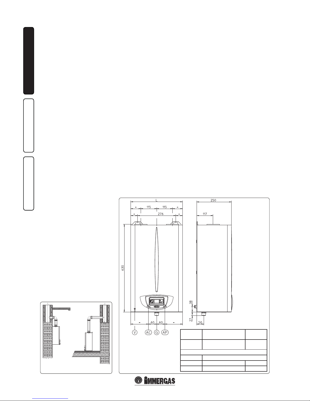
1.2 MAIN DIMENSIONS.
the generator.
e plugs (standard supply) are to be used only in
conjunction with the mounting brackets or xing
template to x the water heater to the wall; they
only ensure adequate support if inserted correctly
(according to technical standards) in walls made
of solid or semi-hollow brick or block. In the
case of walls made from hollow brick or block,
partitions with limited static properties, or in any
case walls other than those indicated, a static test
must be carried out to ensure adequate support.
N.B.: the hex head screws supplied in the blister
pack are to be used exclusively to x the relative
mounting bracket to the wall.
ese appliances are used to heat water to below
boiling temperature in atmospheric pressure.
ey must be connected to a DHW distribution
network suited to their performance and power.
Height
(mm)
Width (mm)
(L)
Depth
(mm)
630
Caesar 14 3 E = 375
Super Caesar 17 3 E = 420
250
CONNECTIONS
GAS DOMESTIC HOT WATER
GACAF
3/4” 1/2” 1/2”
Key:
AC - Domestic hot water outlet
AF - Domestic hot water inlet
G - Gas supply
V - Electrical connection
YES NO
Page 5
1-3
Cavo di alimentazione
5 - IE
INSTALLATORUSERTECHNICIAN
1.3 ANTIFREEZE PROTECTION.
Minimum temperature -15°C. If the water heater
is installed in a place where the temperature falls
below 0°C and in the event there is no gas (or
the water heater goes into ignition block), the
appliance can freeze.
To prevent the risk of freezing follow the instructions
below:
- Protect the condensate drain trap and circuit
board against freezing by using an accessory
that is supplied on request (anti-freeze kit)
comprising two electric heating elements,
the relevant cables and a control thermostat
(carefully read the installation instructions
contained in the accessory kit pack).
Water heater anti-freeze protection is thus ensured
only if:
- the water heater is correctly connected to
electricity power supply circuits;
- main switch is inserted;
- the anti-freeze kit components are ecient.
In these conditions the water heater is protected
against freezing to temperature of -15°C.
The warranty does not cover damage due to
interruption of the electrical power supply and
failure to comply with that stated on the previous
page.
N.B.: if the water heater is installed in places
where the temperature falls below 0°C, the
heating attachment pipes must be insulated.
1.4 ATTACHMENTS.
Gas connection (Appliance category II
2H3+
).
Our water heaters are designed to operate with
methane gas (G20) and LPG. Supply pipes must
be the same as or larger than the 3/4”G water
heater tting. Before connecting the gas line,
carefully clean inside all the fuel feed system
pipes to remove any residue that could impair
water heater eciency. Also make sure the gas
corresponds to that for which the water heater is
prepared (see water heater data-plate). If dierent,
the water heater must be converted for operation
with the other type of gas (see converting
appliance for other gas types). e dynamic gas
supply (methane or LPG) pressure must also be
checked according to the type used in the water
heater, as insucient levels can reduce generator
output and cause malfunctions.
Ensure correct gas cock connection. The gas
supply pipe must be suitably dimensioned
according to current regulations in order to
guarantee correct gas ow to the burner even
in conditions of maximum generator output
and to guarantee appliance eciency (technical
specifications). The coupling system must
conform to standards.
Fuel gas quality. e appliance has been designed
to operate with gas free of impurities; otherwise it
is advisable to t special lters upstream from the
appliance to restore the purity of the gas.
Storage tanks (in case of supply from LPG
depot).
- New LPG storage tanks may contain residual
inert gases (nitrogen) that degrade the mixture
delivered to the appliance casing functioning
anomalies.
- Due to the composition of the LPG mixture,
layering of the mixture components may occur
during the period of storage in the tanks. is
can cause a variation in the heating power of
the mixture delivered to the appliance, with
subsequent change in its performance.
Hydraulic connection
Important: before connecting the water heater
and so as not to make the warranty null and void
on the DHW heat exchanger, wash the system
thoroughly (piping, etc.) in a way to remove
any residues that could compromise the good
functioning of the water heater.
Water connections must be made in a rational
way using the couplings on the water heater
template.
Important: to preserve the duration of appliance
eciency features, in the presence of water whose
features can lead to the deposit of lime scale,
installation of the “polyphosphate dispenser” kit
is recommended . On the basis of the Standards
in force, it is mandatory to treat the supply water
with temporary water hardness over or equal to
25 French degrees in the heating circuit and over
than or equal to 15 French degrees for DHW, using
conditioning chemicals for powers ≤ 100 kW or
with soeners for powers > 100 kW
Electrical connection: e “Caesar” water heater
has an IPX5D protection rating for the entire
appliance. Electrical safety of the appliance is
reached only when it is correctly connected to an
ecient earthing system as specied by current
safety standards.
Important: Immergas S.p.A. declines any
responsibility for damage or physical injury
caused by failure to connect the water heater to
an ecient earth system or failure to comply with
the reference standards.
Also ensure that the electrical installation
corresponds to maximum absorbed power
specications as shown on the water heater dataplate. Water heaters are supplied complete with
an “X” type power cable without plug. e power
supply cable must be connected to a 230V ±10%
/ 50Hz mains supply respecting L-N polarity and
earth connection
is network must also
have an omnipolar circuit breaker with class III
over-voltage category. When replacing the power
supply cable, contact a qualied technician (e.g.
the Immergas Aer-Sales Technical Assistance
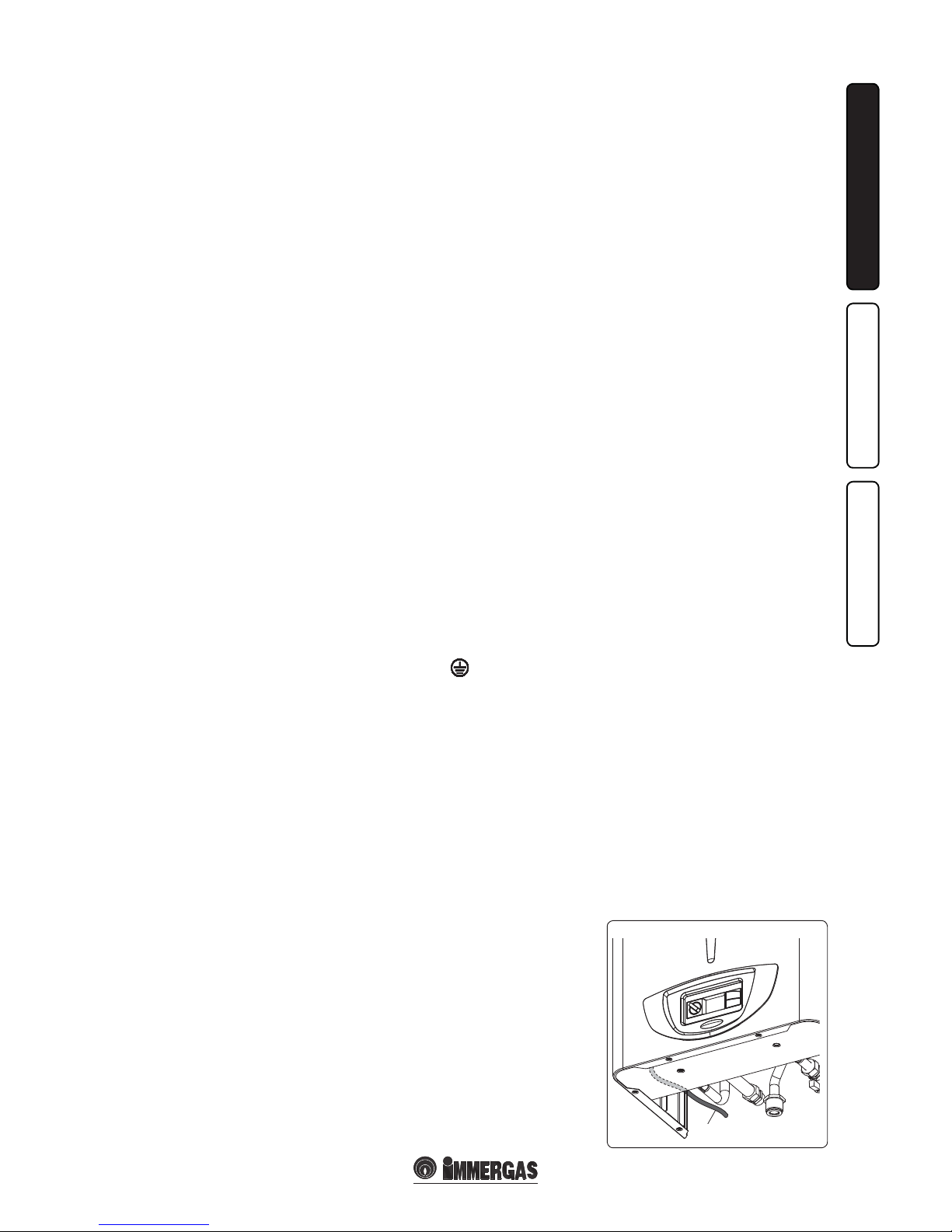
Service). e power cable must be laid as shown
(Fig. 1-3).
In the event of mains fuses replacement on the
connection board, use a 3.15A quick-blow fuses.
For the main power supply to the appliance,
never use adapters, multiple sockets or extension
leads.
N.B.: all water heater pipes must never be used
to earth the electric or telephone lines. Ensure
elimination of this risk before making the water
heater electrical connections.
Power supply cable
Page 6
1-4 1-5
6 - IE
INSTALLATORUSERTECHNICIAN
1.6 OUTDOOR INSTALLATION IN
PARTIALLY PROTECTED AREA.
N.B.: a partially protected area is one in which the
appliance is not exposed to the direct action of the
weather (rain, snow, hail, etc..)..
• Conguration type B, open chamber and
forced draught.
Using the relevant cover kit direct air intake is
possible (Fig. 1-7) and ue gases are exhausted
into a single ue or directly to the outside. In this
conguration it is possible to install the water
heater in a partially protected place.
In this conguration the water heater is classied
as type B
22
.
With this conguration:
- air intake takes place directly from the room
in which the appliance is installed (outdoor);
- the ue exhaust must be connected to its own
individual ue or channelled directly into the
external atmosphere.
The technical regulations in force must be
respected.
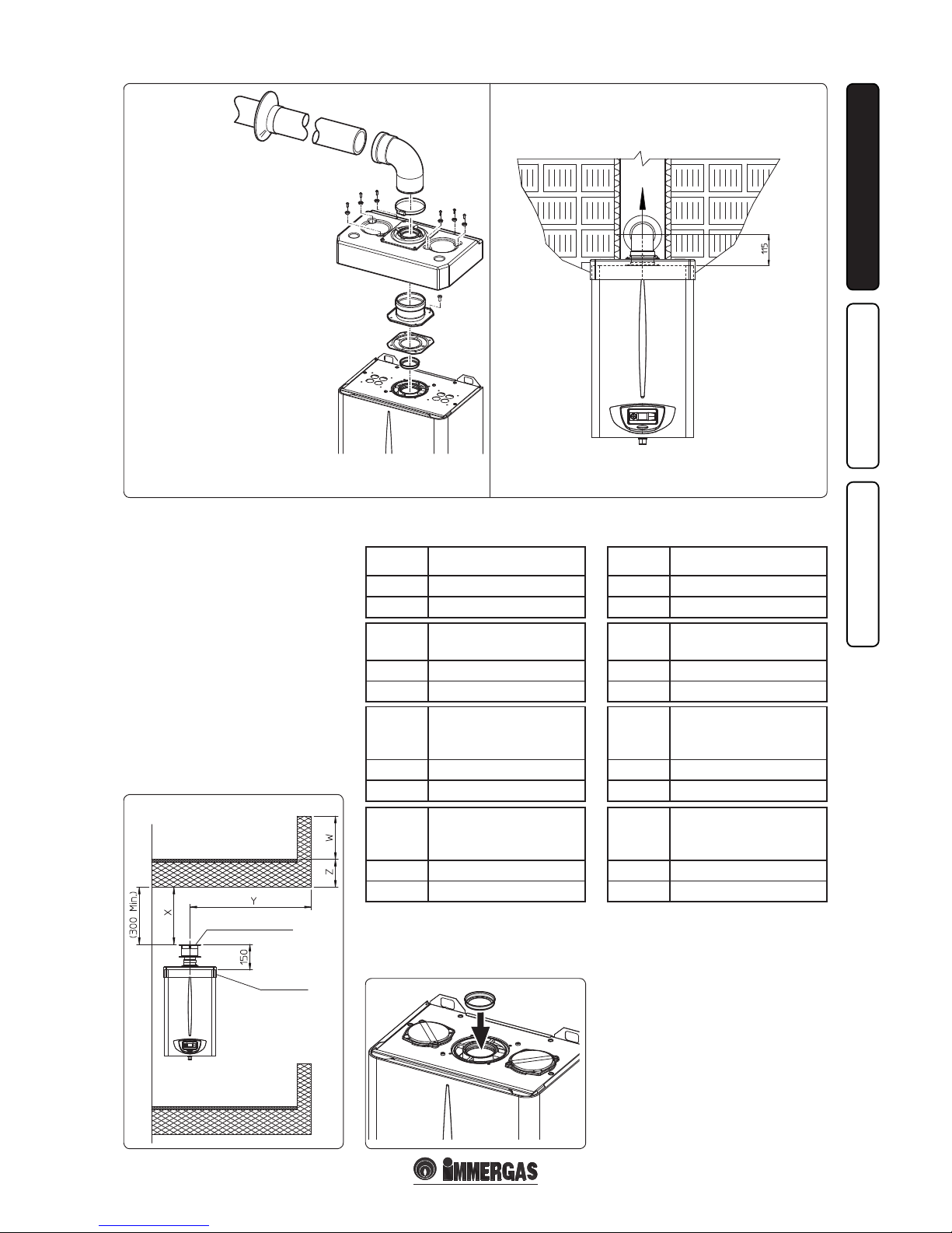
• Cover kit assembly (Fig. 1-6). Remove the
two plugs and the gaskets present from the two
lateral holes with respect to the central one.
Position the diaphragm on the discharge hole:
Caesar 14 3 E: Ø 45 present inn the water
heater.
Super Caesar 17 3 E: Ø 44 present in the
thermoformed kit.
Install the Ø 80 outlet ange on the central
hole of the water heater, taking care to insert
the gasket supplied with the kit and tighten
by means of the screws provided. Install the
upper cover, xing it using the screws and
relevant gaskets present in the kit. Fit the 90° Ø
80 curve with the male side (smooth) into the
female side (with lip seals) of the Ø 80 ange,
up to stop.Cut the gasket in the relevant groove
at the desired diameter (Ø 80), run it along the
curve and x it using the sheet steel plate. Fit
the male end (smooth) of the exhaust terminal
into the the female end of the bend 90° Ø 80,
making sure that the relevant wall sealing
plate is already tted; this will ensure hold and
joining of the elements making up the kit.
• Coupling of extension pipes. To install push-
tting extensions with other elements of the
flue extraction elements assembly, proceed
as follows: Couple the pipe or elbow with the
male side (smooth) in the female side (with lip
seal) to the end stop on the previously installed
element. is will ensure sealing eciency of
the coupling.
Max. length of exhaust duct. The flue pipe
(vertical or horizontal) can be extended to a max.
length of 12 straight metres (Fig. 1-21). To prevent
problems of ue gas condensate in the exhaust
pipe Ø 80, due to ue gas cooling through the
wall,the length of the pipe (not insulated) must
be limited to just 5 m.
Example of installation with direct vertical
terminal in partially protected location. When
the vertical terminal for direct discharge of
combustion products is used, a minimum gap
of 300 mm must be le between the terminal
and the balcony above. e height X+Y+Z+W
evaluated with respect to the balcony above,
must be equal to or more than 2000 mm. (Fig.
1-8). e term W must only be considered if the
balcony above has closed balustrade (W=0 if the
balustrade is open).
• Conguration without cover kit (water heater
type C).
By leaving the side plugs tted, it is possible
to install the appliance externally, in partially
covered places, without the cover kit. Installation
takes place using the Ø60/100 and Ø80/125
concentric horizontal intake/ exhaust kits. Refer
to the paragraph relative to indoor installation. In
this conguration the upper cover kit guarantees
additional protection for the water heater. It is
recommended but not compulsory.
1.5 IMMERGAS FLUE SYSTEMS.
Immergas supplies various solutions separately
from the water heaters regarding the installation
of air intake terminals and ue extraction, which
are fundamental for water heater operation.
Important: the water heater must only be
installed together with an original Immergas
air intake and ue gas exhaust system. is
system can be identied by an identication
mark and special distinctive marking bearing
the note: “not for condensing boilers”.
e ue exhaust pipes must not be in contact with
or be near to ammable materials. Moreover,
they must not pass through buildings or walls
made of ammable material.
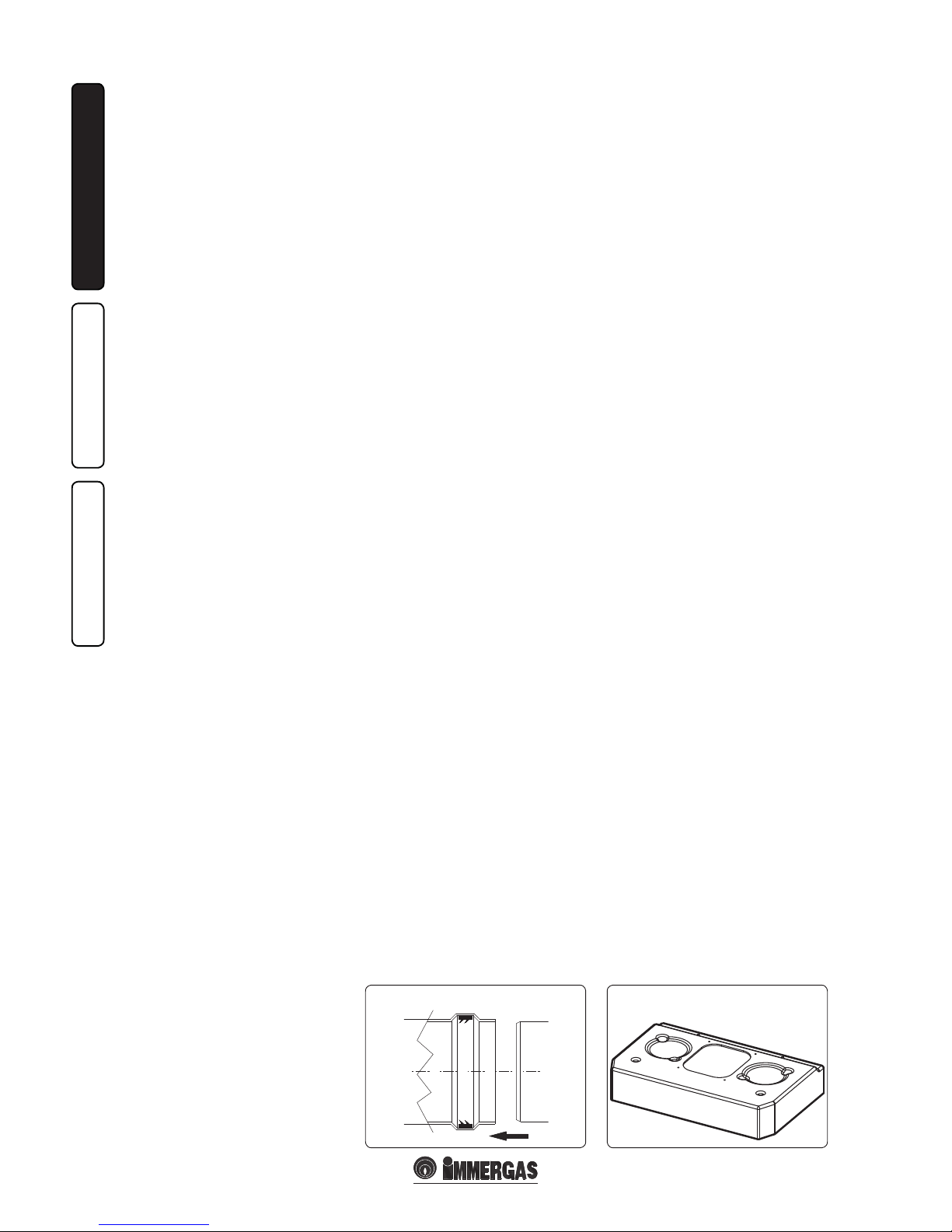
Positioning of double lip seals. For correct
positioning of lip seals on elbows and extensions,
follow the direction of assembly given in gure
(Fig. 1-4).
• Resistance factors and equivalent lengths.
Each ue extraction system component has
a Resistance Factor based on experimental
tests and specified in the table below. The
resistance factor for individual components is
independent from the type of water heater on
which it is installed or the actual dimensions.
It is, however, conditioned by the temperature
of the uids that pass through the pipe and
therefore varies according to applications for
air intake or flue exhaust. Each individual
component has a resistance corresponding to
a certain length in metres of pipe of the same
diameter; the so-called equivalent length,
obtained from the ratio between the relative
Resistance Factors. All water heaters have an
experimentally obtainable maximum Resistance
Factor equal to 100.e maximum Resistance
Factor allowed corresponds to the resistance
encountered with the maximum allowed pipe
length for each type of Terminal Kit. This
information enables calculations to verify the
possibility of various congurations of ue
extraction systems.
Diaphragm installation. For correct functioning
of the water heater, a Ø 45 diaphragm must be
installed on the outlet of the sealed chamber and
before the intake and exhaust pipe for the “Caesar
14 3 E” model and a diaphragm of Ø 46 for the
“Super Caesar 17 3 E” model (Fig. 1-9).
N.B.: the diaphragm is supplied as per standard
with the water heater.
Upper lid
Page 7
1-7
1-8
B22 B22
B22
1-6
1-9
7 - IE
INSTALLATORUSERTECHNICIAN
e terminal kit includes:
N° 1 - Gasket
N° 1 - Exhaust ange Ø 80
N° 1 - Bend 90° Ø 80
N° 1 - Exhaust pipe Ø 80
N° 1 - Wall sealing plate
e cover kit includes:
N° 1 - Heat moulded cover
N° 1 - Ø 44 discharge diaphragm
N°1 - Gasket clamping plate
N° 1 - Gasket
* e values for maximum length are considered
with 1 metre of exhaust pipe and the remaining
on intake.
* e values for maximum length are considered
with 1 metre of exhaust pipe and the remaining
on intake.
Diaphragm
Extension in meters
pipe Ø 60/100 horizontal
Ø 46 From 0 to 1
NONE Exceeding 1
Diaphragm
Extension in meters
pipe Ø 60/100 horizontal
Ø 45 From 0 to 1
NONE Exceeding 1
Diaphragm
Pipe extension in metres Ø
60/100 vertical
Ø 46 From 0 to 2.2
NONE Exceeding 2.2
Diaphragm
Pipe extension in metres Ø
60/100 vertical
Ø 45 From 0 to 2.7
NONE Exceeding 2.7
Diaphragm
*Extension in metres
vertical pipe Ø 80
without bends
Ø 46 From 0 to 22
NONE Exceeding 22
Diaphragm
*Extension in metres
vertical pipe Ø 80
without bends
Ø 45 From 0 to 25
NONE Exceeding 25
Diaphragm
*Extension in meters
horizontal pipe Ø 80 with
two bends
Ø 46 From 0 to 17
NONE Exceeding 17
Diaphragm
*Extension in meters
horizontal pipe Ø 80 with
two bends
Ø 45 From 0 to 20
NONE Exceeding 20
Caesar 14 3 E discharge diaphragm. Caesar 17 3 E Super discharge diaphragm.
INTAKE
COVER KIT
VERTICAL TERMINAL KIT
FOR DIRECT DRAINING
Page 8
8 - IE
INSTALLATORUSERTECHNICIAN
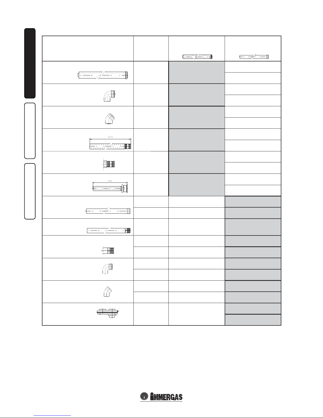
Tables of Resistance Factors and Equivalent Lengths.
DUCT TYPE
Resistance
Factor
(R)
Equivalent
length in m of concentric pipe
Ø 60/100
Equivalent
length
in m of pipe
Ø 80
Concentric pipe Ø 60/100 m 1
Intake and
Exhaust 16.5
m 1
Intake m 7.1
Exhaust m 5.5
Concentric bend 90° Ø 60/100
Intake and
Exhaust 21
m 1.3
Intake m 9..1
Exhaust m 7.0
Concentric bend 45° Ø 60/100
Intake and
Exhaust 16.5
m 1
Intake m 7.1
Exhaust m 5.5
Terminal complete with concentric horizontal
intake-exhaust Ø 60/100
Intake and
Exhaust 46
m 2.8
Intake m 20
Exhaust m 15
Concentric horizontal
intake- exhaust terminal Ø 60/100
Intake and
Exhaust 32
m 1.9
Intake m 14
Exhaust m 10.6
Concentric vertical
intake-exhaust terminal Ø 60/100
Intake and
Exhaust 41.7
m 2.5
Intake m 18
Exhaust 14
Pipe Ø 80 m 1 (with and without insulation)
Intake 2.3 m 0.1 Intake m 1.0
Exhaust 3 m 0.2 Exhaust m 1.0
Complete air intake terminal Ø 80 m 1
(with or without insulation)
Intake 5 m 0.3 Intake m 2.2
Intake terminal Ø 80
Exhaust terminal Ø 80
Intake 3 m 0.2 Intake m 1.3
Exhaust 2.5 m 0.1 Exhaust m 0.8
Bend 90° Ø 80
Intake 5 m 0.3 Intake m 2.2
Exhaust 6.5 m 0.4 Exhaust m 2.1
Bend 45° Ø 80
Intake 3 m 0.2 Intake m 1.3
Exhaust 4 m 0.2 Exhaust m 1.3
Split parallel Ø 80
from Ø 60/100 to Ø 80/80
Intake and
Exhaust 8.8
m 0.5
Intake m 3.8
Exhaust m 2.9
Page 9

C12
1-10
C12
C12
C12
C12
1-11
1-13
1-141-12
1
3
2
4
5
9 - IE
INSTALLATORUSERTECHNICIAN
1.7 INDOOR INSTALLATION.
• Type C conguration, sealed chamber and
fan assisted.
Horizontal intake - exhaust kit Ø60/100. Kit
assembly (Fig. 1-10): install the bend with ange
(2) onto the central hole of the water heater
inserting the gasket (1) and tighten using the
screws in the kit. Couple the terminal pipe (3)
with the male end (smooth) into the female
end of the bend (with lip seals) up to the stop;
making sure that the internal wall sealing plate
and external wall sealing plate have been tted,
this will ensure sealing and joining of the elements
making up the kit.
Note: when the water heater is installed in areas
where very rigid temperatures can be reached,
a special anti-freeze kit is available that can be
installed as an alternative to the standard kit.
• Coupling extension pipes and concentric elbows
Ø 60/100. To snap-t extensions with other
elements of the ue gas extraction elements,
operate as follows Install the concentric pipe
or elbow with the male side (smooth) on the
female section (with lip seal) to the end stop on
the previously installed element. is will ensure
the sealing and joining of the elements correctly.
e Ø 60/100 horizontal intake/exhaust kit can
be installed with the rear, right side, le side and
front outlet.
• Application with rear outlet (Fig. 1-11). e 788
mm pipe length enables routing through a wall
with maximum thickness of 788 mm. Normally
the terminal must be shortened. Calculate the
distance by adding the following values: Part
thickness + internal projection + external
projection. The minimum indispensable
projection values are given in the gure.
• Application with lateral output (Fig. 1-12); Only
using the horizontal intake-exhaust kit, without
the relevant extensions, permits to pass through
a wall with thickness of 715.5 mm with the
Caesar 14 3 E and of 705 mm with the Super
Caesar 17 3 E (height “X”), both with le and
right lateral output.
• Extensions for horizontal kit. e horizontal
intake-exhaust kit Ø 60/100 can be extended
up to a max. horizontal distance of 3000
mm including the terminal with grid and
excluding the concentric bend leaving the
water heater. is conguration corresponds
to a resistance factor of 100. In these cases the
special extensions must be requested.
Connection with N°1 extension (Fig. 1-13).
Max. distance between vertical water heater axis
and external wall is 1855mm.
Connection with N°2 extensions (Fig. 1-14).
Max. distance between vertical water heater axis
and external wall is 2805mm.
e kit includes:
N°1 - Gasket (1)
N°1 - Concentric bend 90° (2)
N°1 - Intake/exhaust concentric pipe
Ø60/100 (3)
N°1 - Internal white wall sealing plate (4)
N°1 - External grey wall sealing plate (5)
• External grill. N.B.: for safety purposes, do
not even temporarily obstruct the water heater
intake-exhaust terminal.
Page 10

C32
1-171-16
C32
1
2
3
4
5
7
6
10 - IE
INSTALLATORUSERTECHNICIAN
Vertical kit with aluminium tile Ø 60/100.
Kit assembly (Fig. 1-16): install the concentric
ange (2) on the central hole of the water heater
inserting the gasket (1) and tighten using the
screws in the kit. Imitation aluminium tile
installation. Replace the tile with the aluminium
sheet (4), shaping it to ensure that rainwater
runs o. Position the xed half-shell (6) and
insert the intake-exhaust pipe (5). Fit the Ø
60/100 concentric terminal pipe with the male
end (5) (smooth) to the female end of the ange
(2) (with lip gasket) up to the stop; making sure
that the wall sealing plate (3) has been tted, this
will ensure sealing and joining of the elements
making up the kit.
• Coupling extension pipes and concentric
elbows. To install push-fitting extensions
with other elements of the flue extraction
elements assembly, proceed as follows: Install
the concentric pipe or elbow with the male
side (smooth) on the female section (with lip
seal) to the end stop on the previously installed
element. is will ensure sealing and joining of
the elements correctly.
Important: if the exhaust terminal and/or
extension concentric pipe needs shortening,
consider that the internal duct must always
protrude by 5 mm with respect to the external
duct.
is specic terminal enables ue exhaust and
air intake, necessary for combustion, in a vertical
direction.
N.B.: the Ø 60/100 vertical kit with aluminium
tile enables installation on terraces and roofs with
a maximum slope of 45% (25°) and the height
between the terminal cap and half-shell (374
mm) must always be respected.
e vertical kit with this conguration can be
extended up to a maximum of 4700 mm vertical
rectilinear, with the terminal included (Fig. 1-17).
is conguration corresponds to a resistance
factor of 100. In this case the special extensions
must be requested.
Separator kit Ø 80/80. e Ø 80/80 separator
kit, allows separation of the exhaust ues and
air intake pipes according to the diagram shown
in the gure.
Combustion products are expelled from pipe (S).
Air is taken in through pipe (A) for combustion.
e intake pipe (A) can be installed either on the
right or le hand side of the central exhaust pipe
(S). Both ducts can be routed in any direction.
• Kit assembly (Fig. 1-18): install ange (4) on
the central hole of the water heater, tting
gasket (1) and tighten with the at-tipped hex
screws included in the kit. Remove the at
ange present in the lateral hole with respect
to the central one (according to needs) and
replace it with the ange (3), positioning the
gasket (2) already present in the water heater
and tighten using the supplied self-threading
screws. Fit the male end (smooth) to the bends
(5) in the female end of the anges (3 and 4).
Fit the intake terminal (6) with the male section
(smooth) in the female section of the bend (5)
up to the stop, ensuring that the internal and
external wall sealing plates are tted. Fit the
exhaust pipe (9) with the male end (smooth)
to the female end of the bend (5) up to the stop;
making sure that the internal wall sealing plate
has been tted, this will ensure sealing and
joining of the elements making up the kit.
• Coupling of extension pipes and elbows. To
install push-fitting extensions with other
elements of the flue extraction elements
assembly, proceed as follows: Install the pipe
or elbow with the male side (smooth) on the
female section (with lip seal) to the end stop
on the previously installed element. is will
ensure sealing and joining of the elements
correctly.
• Installation clearances. Figure 1-19 gives the
min. installation space dimensions of the
Ø 80/80 separator terminal kit in limited
conditions.
• Figure 1-20 shows the configuration with
vertical exhaust and horizontal intake.
• Extensions for the separator kit Ø 80/80.
The max. vertical straight length (without
bends) that can be used for Ø 80 intake and
exhaust pipes is 41 metres of which 40 intake
and 1 exhaust. e total length corresponds
to a resistance factor of 100. e total usable
length obtained by adding the length of the
intake and exhaust pipes Ø 80, must not
exceed the values stated in the following table.
If mixed accessories or components are used, t he
maximum extension can be calculated by using
a resistance factor for each component or its
equivalent length. e sum of these resistance
factors must not exceed 100.
e kit includes:
N°1 - Gasket (1)
N°1 - Female concentric
ange (2) (sold sepa-
rately)
N°1 - Wall sealing plate (3)
N°1 - Aluminium tile (4)
N°1 - Int./exhaust concentric
pipe Ø 60/100 (5)
N°1 - Fixed half-shell (6)
N°1 - Mobile half-shell (7)
MAXIMUM LENGTH 4700 mm
Page 11

C82
1-18
C42
C52
1-19
1-21
C82
A
S
7
6
8
3
2
5
1
4
4
9
1-20
11 - IE
INSTALLATORUSERTECHNICIAN
e kit includes:
N°1 - Exhaust gasket (1)
N°1 - Female intake ange (3)
N°1 - Flange gasket (2)
N°1 - Female exhaust ange (4)
N°2 - 90° bend Ø 80 (5)
N°1 - Intake terminal Ø 80 (6)
N°2 - Internal white wall sealing plates (7)
N°1 - External grey wall sealing plate (8)
N°1 - Exhaust pipe Ø 80 (9)
Important: if the installation requests a
development of the flue to the discharge
that exceeds the recommended 12 m, due
consideration must be given to the formation of
condensate that could take place inside the pipe
and Immergas insulated “Blue Series” ue kits
must be used.
• Conguration type B, open chamber and
forced draught.
When using type B installation conguration
indoors, it is compulsory to install the relative
upper cover kit along with the ue gas discharge
kit. e air intake comes directly from the area
where the water heater is installed and from the
ue exhaust in each single ue or directly from
outdoors.
e water heater in this conguration, following
the assembly instructions stated in the par. 1.6 is
classied as type B
22
.
With this conguration:
- air intake takes place directly from the
environment in which the boiler is installed and
only functions in permanently ventilated rooms;
- the ue exhaust must be connected to its own
individual ue or channelled directly into the
external atmosphere.
- type B open chamber water heaters must not be
installed in places where commercial, artisan
or industrial activities take place, which use
products that may develop volatile vapours
or substances (e.g. acid vapours, glues, paints,
solvents, combustibles, etc.), as well as dusts (e.g.
dust deriving from the working of wood, coal
nes, cement, etc.). ese may be damaging for
the components of the appliance and jeopardise
functioning.
- in type B
22
conguration, the water heaters must
not be installed in bedrooms or bathrooms.
On installation indoors in type B conguration
it is mandatory to install the relevant top cover
kit along with the ue gas exhaust kit.
The technical regulations in force must be
respected.
Maximum usable lengths
(including intake terminal with grill and two 90° bends)
NON-INSULATED PIPE INSULATED PIPE
Drain (metres) Intake (metres) Drain (metres) Intake (metres)
1 36.0* 6 29.5*
2 34.5* 7 28.0*
3 33.0* 8 26.5*
4 32.0* 9 25.5*
5 30.5* 10 24.0*
* e air intake pipe can be increased to 2.5 metres if the exhaust bend
is eliminated. 2 metres if the air intake bend is eliminated. 4.5 metres
eliminating both bends.
11 22.5*
12 21.5*
Page 12

12 - IE
INSTALLATORUSERTECHNICIAN
1.8 FLUE EXHAUST TO FLUE/CHIMNEY.
Flue exhaust does not necessarily have to be
connected to a branched type traditional ue.
e discharge of ue gases, just for the water
heaters installed in configuration C, can be
connected to a particular LAS type collective ue.
For B
22
congurations, discharge is only allowed
into individual ue or directly into the outside
atmosphere by the relevant terminal. Multiple
and combined ues must be specially designed
according to the calculation method and
requirements of the standards, by professionally
qualied technical sta. Chimney or ue sections
for connection of the exhaust pipe must comply
with requisites of technical standards in force.
1.9 DUCTING OF FLUES OR
TECHNICAL SLOTS.
With a specic “ducting system” it is possible to
reuse existing ues, chimneys and existing or
new technical slots to discharge the water heater
ue gases. Ducting requires the use of ducts
declared to be suitable for the purpose by the
manufacturer. Follow the installation and user
instructions provided by the manufacturer and
the requirements of standards.
1.10 FLUES, CHIMNEYS AND CHIMNEY
CAPS.
e ues, chimneys and chimney caps for the
evacuation of combustion products must be in
compliance with applicable standards.
Positioning the exhaust terminals. e exhaust
terminals must:
- be installed on external perimeter walls of the
building;
- be positioned according to the minimum
distances specified in current technical
standards.
Combustion products exhaust of natural or
fan assisted appliances in open-top closed
environments. In spaces closed on all sides
with open tops (ventilation pits, courtyards etc.),
direct ue gas exhaust is allowed for natural or
forced draught gas appliances with a heating
power range from 4 to 35 kW, provided the
conditions as per the current technical standards
are respected.
1.11 GAS SYSTEM STARTUP.
To start up the system, make reference to the
Standard: is divides the systems and therefore
the start-up operations into three categories: new
systems, modied systems, re-activated systems.
In particular, for new gas systems:
- open windows and doors;
- avoid presence of sparks or naked ames;
- bleed all air from pipelines;
- check that the internal system is properly sealed
according to specications.
1.12 WATER HEATER START UP
IGNITION.
For issue of the Declaration of Conformity
provided for by Italian Law, the following must
be performed for water heater start-up:
- check that the internal system is properly sealed
according to specications;
- ensure that the type of gas used corresponds to
water heater settings;
- switch the water heater on and ensure correct
ignition;
- make sure that the gas ow rate and relevant
pressure values comply with those given in the
manual (par. 3.13);
- ensure that the safety device is engaged in the
event of gas supply failure and check activation
time;
- check activation of the main switch located
upstream from the water heater;
- check that the concentric intake-exhaust
terminal (if tted) is not blocked.
e water heater must not be started up even if
only one of the checks should be negative.
N.B.: the water heater preliminary check must
be carried out by a qualified technician. The
conventional water heater warranty is valid as of
the date of testing.
e test certicate and warranty is issued to the
user.
1.13 KITS AVAILABLE ON REQUEST.
• Polyphosphate dispenser kit. e polyphosphate
dispenser reduces the formation of lime-scale
and preserves the original heat exchange and
domestic hot water production conditions. e
water heater is prepared for application of the
polyphosphate dispenser kit.
• Covering kit. For outdoor installations, in
partially protected areas and with direct air
intake, the top protection cover must be tted
for a correct functioning of the water heater
and to protect it from storms (Fig. 1-8). For
indoor installations, type B conguration, a
suitable top protection cover coupled with the
ue exhaust kit must be tted.
• Anti freeze kit with resistance (on request). If
the water heater is installed in a place where the
temperature falls below 0°C and the appliance
can freeze. To prevent freezing of the domestic
hot water system, an anti freeze kit with an
electrical resistance can be fitted from the
relative cable and from a control thermostat.
• Bracket kit for Omni Container. If necessary,
the water heater can be installed inside the
Omni Container. For assembly, use the relevant
support bracket contained in the kit.
e above-mentioned kits are supplied complete
with instructions for assembly and use.
Page 13

1- 22
13 - IE
INSTALLATORUSERTECHNICIAN
1.14 WATER HEATER COMPONENTS.
Key:
1 - Sealed chamber
2 - Fan
3 - DHW heat exchanger
4 - Ignition/detection electrode
5 - Gas valve
6 - Flue pressure switch
7 - Safety thermostat
8 - Flue hood
9 - DHW probe (hot water output)
10 - Combustion chamber
11 - Burner
12 - Gas manifold
13 - Flow limiter
14 - One-way valve
15 - Flow rate meter
16 - Domestic water inlet cock
17 - DHW probe (cold water input)
Page 14

2-1
14 - IE
INSTALLATORUSERTECHNICIAN
2
INSTRUCTIONS FOR USE
AND
MAINTENANCE.
2.1 CLEANING AND MAINTENANCE.
e appliance must be serviced every year.
is ensures that the optimal safety, performance
and operation characteristics of the water heater
remain unchanged over time.
2.2 GENERAL WARNINGS
Never expose the wall-mounted water heater to
direct vapours from a cooking surface.
Use of the water heater by unskilled persons or
children is strictly prohibited.
Do not touch the ue gas exhaust terminal (if
present) due to the high temperatures it can
reach;
For safety purposes, check that the concentric
air intake/flue exhaust terminal (if fitted), is
not blocked.
Whenever temporary deactivation of the water
heater is decided, the electric, water and gas
supplies must be interrupted.
In the case of work or maintenance to structures
located in the vicinity of ducting or devices
for flue extraction and relative accessories,
switch o the appliance and on completion of
operations ensure that a qualied technician
checks eciency of the ducting or other devices.
Never clean the appliance or connected parts
with easily ammable substances.
Never leave containers or ammable substances
in the same environment as the appliance.
• Important: the use of components involving
use of electrical power requires some
fundamental rules to be observed:
- do not touch the appliance with wet or moist
parts of the body; do not touch when barefoot;
- never pull electrical cables or leave the
appliance exposed to atmospheric agents (rain,
sunlight, etc.);
- the appliance power cable must not be replaced
by the user;
- in the event of damage to the cable, switch o
the appliance and contact exclusively qualied
sta for replacement;
- if the appliance is not to be used for a certain
period, disconnect the main power switch.
2.3 CONTROL PANEL.
Key:
1 - On/Stand-by/O Button
2 - Reset button
3 - Temperature selector
4 - Domestic hot water function
5 - Temperature and error code display
6 - Unit of measurement
7 - Not used on this model
8 - Not used on this model
9 - Not used on this model
10 - Output eciency
11 - Flame presence
Page 15

15 - IE
INSTALLATORUSERTECHNICIAN
2.4 USE OF THE WATER HEATER.
Ignition (Fig. 2-1). Before ignition, check that
the DHW inlet valve is open.
- Open the gas cock upstream from the water
heater.
- Press the button (1) until the display switches
on; pressing the button passes cyclically from
the “off ”, “stand-by” and “on” state of the
appliance.
- Regulate the DHW temperature according to
requirements by turning the selector (3).
Turning in a clockwise direction the
temperature increases and in an anti-clockwise
direction it decreases.
From this moment the water heater functions
automatically. If there is no request for DHW, it
goes to "Stand-by" which is equal to water heater
powered without ame presence. e display
shows the temperature of the water inside the
water heater (5). Each time the burner ignites,
the relative ame present symbol is displayed
(11) with relative power scale (10). Moreover, the
indication of the instant temperature supplied
by the water heater is supplied.
• “Stand-by” mode. Repeatedly press the
button (1) until the (
) symbol appears. e
water heater is inactive from this moment.
e indication of any anomalies is however
guaranteed.
N.B.: in these conditions the water heater is
considered still powered.
• “O” mode. Press button (1) repeatedly until
the display switches o. In this way the water
heater is o completely.
N.B.: in these conditions the water heater
is considered still live even if there are no
functions active.
2.5 FAULT AND ANOMALY SIGNALS.
The water heater signals out anomalies by
ashing on the display and relative error codes,
listed on the table, are displayed.
Anomaly signalled
code
displayed
(ashing)
No ignition block 01
Over-heating (safety) thermostat block
02
Domestic hot water probe
anomaly
06
Maximum N° of reset 08
Flue pressure switch failure 11
Domestic hot water inlet
probe anomaly
12
Parasite ame 20
Push button control panel
anomaly
24
Low power supply voltage 37
Ignition block. The water heater ignites
automatically with each demand for hot water
production. If this does not occur within 10
seconds, the water heater goes into ignition block
(code 01). To eliminate “ignition block” the Reset
button (2) must be pressed. On commissioning
or aer extended inactivity it may be necessary to
eliminate the “ignition block”. If this phenomenon
occurs frequently, contact a qualied technician
for assistance (e.g. Immergas Aer-Sales Technical
Assistance Service).
Overtemperature thermostat block. During
normal functioning, if a fault causes excessive
overheating internally, the water heater goes into
overtemperature block (code 02). Aer allowing
to cool, eliminate the "overtemperature block" by
pressing the Reset key (2). If this phenomenon
occurs frequently, contact a qualied technician
for assistance (e.g. Immergas Aer-Sales Technical
Assistance Service).
Domestic hot water probe anomaly. If the board
detects an anomaly on the delivery probe (code
06), the water heater will not start; contact a
qualied technician for assistance (e.g. Immergas
Aer-Sales Technical Assistance Service).
Maximum N° of reset. To eliminate any “anomaly”
the Reset button (2) must be pressed. e Anomaly
can be reset 5 times consecutively, aer which the
function in inhibited for at least one hour. One
attempt is gained every hour for a maximum of
5 attempts.
Flue gas pressure switch failure. is occurs if the
intake or exhaust pipes are blocked, in case of a fan
fault or a fault on the ue gas pressure switch (code
11). If normal conditions are restored the water
heater restarts without having to be reset. If this
anomaly persists, contact a qualied technician
for assistance (e.g. Immergas Aer-Sales Technical
Assistance Service).
Domestic hot water inlet probe anomaly. If the
board detects an anomaly on the domestic hot
water NTC probe, the water heater signals the
anomaly. In this case the water heater continues to
produce domestic hot water but not with optimal
performance. A qualified technician however
must be called (e.g. Immergas Aer-Sales Service).
Parasi te ame. is occ urs in case of a leak on the
detection circuit or anomaly in the ame control
unit.(code 20), try to reset the water heater. If the
anomaly continues contact a qualied technician
(e.g. Immergas Aer-Sales Technical Assistance
Service).
Push button control panel anomaly. is occurs
when the circuit board detects an anomaly on the
push button control panel. If normal conditions are
restored the water heater restarts without having
to be reset. If this anomaly persists, contact a
qualied technician for assistance (e.g. Immergas
Aer-Sales Technical Assistance Service).
Low power supply voltage is occurs when the
power supply voltage is lower than the allowed
limits for the correct functioning of the water
heater. If normal conditions are restored the
water heater restarts without having to be reset.
If this phenomenon occurs frequently, contact a
qualied technician for assistance (e.g. Immergas
Aer-Sales Technical Assistance Service).
2.6 INFORMATION MENU.
Pressing the button (2) for 8 seconds, the
“Information menu” is activated, which allows to
display some water heater functioning parameters.
To scroll the various parameters, press the button
(2), to exit the menu, press the button (1) or wait
for 15 minutes.
List of parameters.
N°
parameter
Description
d1
Displays the instant DHW ow
rate (l/min)
d2
Displays the temperature of the
inlet water on the water heater.
d3
Displays the temperature of
the outlet water from the water
heater.
d4
Displays the temperature set
on the water heater via the
temperature selector (3)
2.7 SWITCHOFF OF THE WATER
HEATER.
Press the button (1 Fig. 2-1) (
) until the
display is switched o completely.
N.B.: in these conditions the water heater is
considered still powered.
Disconnect the external omnipolar water heater
switch and close the gas cock upstream of the
appliance. Never leave the water heater switched
on if le unused for prolonged periods.
2.8 EMPTYING THE WATER HEATER.
To empty the water heater, close the cold water
inlet valve and open the hot water valve lower
down in the water network in the room.
2.9 ANTIFREEZE PROTECTION
OPTIONAL.
The water heater can be equipped with an
optional anti-freeze kit, which protects it from
freezing to outdoor temperatures of -15°C. For
correct installation of the kit and especially
to guarantee appropriate functioning, the
instructions supplied with the kit itself must
be followed.
2.10 CASE CLEANING.
Use damp cloths and neutral detergent to clean
the water heater casing. Never use abrasive or
powder detergents.
2.11 DECOMMISSIONING.
In the event of permanent shutdown of the
water heater, contact professional staff for
the procedures and ensure that the electrical,
water and gas supply lines are shut off and
disconnected.
Page 16

3-1
16 - IE
INSTALLATORUSERTECHNICIAN
3
CONTROL AND MAINTENANCE
3.1 HYDRAULIC DIAGRAM.
Key:
1 - Fan
2 - Sealed chamber
3 - Safety thermostat
4 - Primary heat exchanger
5 - DHW probe (hot water output)
6 - Burner
7 - Gas valve
8 - Flue pressure switch
9 - Flue hood
10 - One-way valve
11 - Flow limiter
12 - Flow rate meter
13 - DHW probe (cold water input)
14 - Domestic hot water inlet valve
AC - Domestic hot water outlet
AF - Domestic cold water inlet
G - Gas supply
Page 17

3-2
17 - IE
INSTALLATORUSERTECHNICIAN
3.2 WIRING DIAGRAM.
3.3 TROUBLESHOOTING
N.B.: maintenance interventions must be carried
out by a qualified technician (e.g. Immergas
Aer-Sales Technical Assistance Service).
- Smell of gas. Caused by leakage from gas circuit
pipelines. Check sealing eciency of gas intake
circuit.
- e fan works but ignition discharge does not
occur on the burner ramp. e fan may start
but the safety air pressure switch does not
switch the contact over. Make sure:
1) 1) the intake-exhaust duct is not too long
(over allowed length).
2) 2) the intake-exhaust pipe is not partially
blocked (on the exhaust or intake side).
3) the diaphragm of the flue gas exhaust is
adequate for the length of the intake-exhaust
duct.
4) that the sealed chamber is kept in good
conditions.
5) the fan power supply voltage is not less than
196 V.
- Irregular combustion (red or yellow ame).
is may be caused by: dirty burner, incorrect
combustion parameters, intake - exhaust
terminal not correctly installed. Clean
the above components and ensure correct
installation of the terminal.
- Frequent activation of the overheating
temperature or safety thermostat. It can depend
on an anomaly on the water heater P.C.B. or and
anomaly of the regulation NTC probe.
- Ignition block see par. 2.6 and 1.4 (electric
connection).
- Low water ow: if, as a result of lime scale
(calcium and magnesium), the domestic hot
water system does not work properly contact a
qualied technician for descaling e.g. Immergas
Aer-Sales Technical Service according to good
practice. To preserve integrity and eciency
of the heat exchanger, a non corrosive descaler
must be used. Cleaning must be carried out
without the use of tools which can damage the
heat exchanger.
3.4 CONVERTING THE WATER HEATER
TO OTHER TYPES OF GAS.
If the boiler has to be converted to a dierent gas
type to that specied on the data plate, request
the relative conversion kit for quick and easy
conversion.
Boiler conversion must be carried out by a
qualied technician (e.g. Immergas Aer-Sales
Technical Assistance Service).
To convert to another type of gas the following
operations are required:
- remove the voltage from the appliance;
- replace the main burner injectors, making sure
to insert the special seal rings supplied in the
kit, between the gas manifold and the injectors;
- apply voltage to the appliance;
- Use the push button control panel to select the
gas parameter type (P2) and then select (nG)
in case of Methane supply or (LG) in the case
of LPG;
- adjust the water heater nominal heat output;
- adjust the water heater minimum heat output;
- seal the gas ow rate devices (if adjusted);
- aer completing conversion, apply the sticker,
present in the conversion kit, near the dataplate. Using an indelible marker pen, cancel
the data relative to the old type of gas.
ese adjustments must be made with reference
to the type of gas used, following that given in
the table (Par. 3.13).
3.5 CHECKS FOLLOWING
CONVERSION TO ANOTHER TYPE
OF GAS.
Aer making sure that conversion was carried
out with a nozzle of suitable diameter for the
type of gas used and the settings are made at the
correct pressure, check that:
- there is no ame in the combustion chamber
- the burner ame is not too high or low and that
it is stable (does not detach from burner)
- the pressure testers used for calibration are
perfectly closed and there are no leaks from
the gas circuit.
N.B.: all water heater adjustment operations
must be carried out by a qualied technician
(e.g. Immergas Aer-Sales Technical Assistance).
Burner adjustment must be carried out using a
dierential "U" or digital type pressure gauge,
connected to a Y-shaped pipes to be placed on
the small silicone pipe that goes from the gas
valve to the sealed chamber and to the gas valve
outlet pressure point (part. 4 g. 3-3), keeping
to the pressure value given in the table par. 3.13
according to the type of gas for which the water
heater is prepared.
Key:
B2 - Domestic hot water probe
B6 - Domestic hot water ow meter
B9 - DHW inlet probe
DS1 - Display
E3 - Ignition/detection electrodes
F1 - Phase fuse
F2 - Neutral fuse
M20 - Fan
R5 - Domestic hot water temperature selector
S2 - Stand-by - On Button
S3 - Reset button
S6 - Flue pressure switch
T2 - Ignition transformer
Y1 - Gas valve
Y2 - Gas valve modulator
230 Vac
50 Hz
Power supply
Blue
Blue
Blue
Brown
Brown
Brown
Black
Black
Black
Black
Black
Red
Condenser
Red
Red
White
Grey
Grey
White
White
White
Yellow/Green
THE X6 CONNECTOR IS
USED FOR AUTOMATIC
INSPECTION
N.B. THE USER INTERFACE
IS ON THE WELDING SIDE
OF THE BOILER BOARD
Page 18

3-3
18 - IE
INSTALLATORUSERTECHNICIAN
SIT 845 Gas Valve
Key:
1 - Coil
2 - Minimum power adjustment screws
3 - Maximum power adjustment screw
4 - Gas valve outlet pressure point
5 - Gas valve inlet pressure point
6 - Protection hood
3.6 POSSIBLE ADJUSTMENTS
• Adjustment of nominal heat output (Fig. 3-3).
- Turn the hot water selector knob (3 Fig. 2-1)
to the maximum functioning position;
- Open the domestic hot water cock in order to
prevent modulation intervention.
- Adjust the water heater nominal power on the
brass nut (3), keeping to the maximum pressure
values stated in the tables (Par. 3.13) depending
on the type of gas.
- By turning in a clockwise direction the heating
potential increases and in an anti-clockwise
direction it decreases.
• Adjustment of minimum heat output (Fig. 3-3).
N.B.: only proceed aer having calibrated the
nominal pressure.
Adjustment of the minimum thermal input
is obtained by operating on the cross plastic
screws (2) on the gas valve maintaining the
brass nut blocked (3);
- disconnect the power supply to the modulating
coil (just disconnect a faston); By turning the
screw in a clockwise direction, the pressure
increases, in an anti-clockwise direction it
decreases. On completion of calibration, reapply the power supply to the modulating
coil. e pressure to which the water heater
minimum power must be adjusted, must not
be lower than that stated in the table (Par. 3.13)
depending on the type of gas.
N.B.: to adjust the gas valve, remove the plastic
cap (6); aer adjusting, ret the cap.
3.7 PROGRAMMING THE P.C.B.
The water heater is prepared for possible
programming of several operation parameters.
By modifying these parameters as described
below, the water heater can be adapted according
to specic needs.
To access the programming phase, proceed as
follows:
- press keys (1) and (2) at the same time for
approximately 10 seconds, keeping the selector
(3) at minimum;
- using key (2), select the parameter to be
changed indicated in the following table:
List of
param-
eters
Description
P1 Solar delay timing
P2 Gas type selection
P3 Ignition power value
P4 Display lighting
- adjust the corresponding value consulting the
following tables by turning the selector (3);
- conrm the value set by pressing the Reset
button (2) for about 3 seconds.
e value ashes when it is memorised.
N.B.: aer a period of time, without touching
any keys, the operation cancels automatically.
Solar delay timing.e water heater is set to
switch-on immediately aer a request for DHW
In the case of coupling with a solar storage tank
positioned upstream from the water heater, it
is possible to compensate the distance between
the storage tank and the water heater in order
to allow the water to reach the water heater. Set
the time necessary to verify that the water is hot
enough (see par. Solar panels coupling)
Solar delay timing
Range of values which can
be set
Parameter
From 0 to 60 sec. (0 Standard
setting)
P1
Gas type selection. e setting of this function
is used to adjust the water heater in order to
function with LPG gas or Methane gas.
Gas type selection
Range of values which can
be set
Parameter
G Town gas (rst family gas)
LG (LPG) or nG (Methane)
(nG Standard setting)
P2
Ignition power value. The water heater has
electronic modulation that adapts the ignition
power according to requirement.
Ignition power value
Range of values which can
be set
Parameter
from 0 % to 50 % (35 % Stand-
ard setting)
P3
Display lighting. Establishes the display lighting
mode.
0 O: the display is always o.
1 Automatic: the display lights up when the water
heater is used.
2 On: e display is always lit up.
Display lighting
Range of values which can
be set
Parameter
0 - 1 - 2 (1 Standard setting) P4
3.8 AUTOMATIC SLOW IGNITION
FUNCTION WITH TIMED RAMP
DELIVERY.
In the ignition phase, the burner ignites at the
"ignition power value" set (P3), aer which, on
the basis of the DHW withdrawal it carries out
a gas supply increasing ramp (with pressure
values that depend on the type of gas selected)
with a pre-dened duration. is prevents every
calibration or precision adjustment of the water
heater ignition phase in any conditions of use.
Page 19

19 - IE
INSTALLATORUSERTECHNICIAN
3.9 SOLAR FUNCTION.
e solar function is always active.
During a request for DHW, if the inlet
temperature is the same as or higher than -3°C
with respect to the value set, the water heater
does not switch-on.
Functioning is however shown on the display by
the ashing of the relevant signal (4).
3.10 SOLAR PANELS COUPLING
FUNCTION.
e water heater is set-up to receive pre-heated
water from a system of solar panels up to a
maximum temperature of 65°C. In all cases, it is
always necessary to install a mixing vale on the
hydraulic circuit upstream from the water heater
on the cold water inlet.
Note: for good functioning of the water heater;
the temperature selected on the mixing valve
must be 5 °C greater with respect to the
temperature selected on the water heater control
panel.
In this condition, parameter P1 (solar delay
timing) must be set at a temperature sucient
to receive water from a storage tank situated
upstream from the water heater. e greater the
distance from the storage tank, the longer the
stand-by time to be set. When these regulations
have been performed, when the water heater inlet
water is at the same or greater temperature with
respect to that set by the DHW selector switch,
the water heater does not switch on.
3.11 YEARLY APPLIANCE CHECK AND
MAINTENANCE.
e following checks and maintenance should
be performed at least once a year.
- Clean the ue side of the heat exchanger.
- Clean the main burner.
- Visually check the ue hood for deterioration
or corrosion.
- Check correct lighting and operation.
- Check correct burner calibration.
- Check correct operation of control and
adjustment devices and in particular:
- the intervention of the functioning selector
positioned on the water heater control panel;
- domestic hot water control thermostat
intervention.
- Check that the internal system is properly
sealed according to specications.
- Check the intervention of the device against no
gas ionisation ame control. Intervention time
must be less than 10 seconds.
- Visually check for water leaks or oxidation
from/on connections.
- Check visually that the safety and control
devices have not been tampered with and/or
shorted, in particular:
- temperature safety thermostat;
- air pressure switch
- Check the condition and integrity of the
electrical system and in particular:
- electrical power cables must be inside the
whipping;
- there must be no traces of blackening or
burning.
Page 20

3-5
c
4
4
d
d
2
a
3
1
a
a
1
1
1
b
20 - IE
INSTALLATORUSERTECHNICIAN
3.12 CASING REMOVAL.
To facilitate water heating maintenance the
casing can be completely removed as follows:
(Fig. 3-5):
1) Loosen the lower screws (a) that x the lower
protection grid (b) and the casing (c).
2) Widen the casing (c) pulling the sides slightly
outwards.
3) Pull the casing towards yourself in the lower
side.
4) Push the casing upwards in a way to be able
to extract it from the upper hooks (d).
Page 21

21 - IE
INSTALLATORUSERTECHNICIAN
3.13 VARIABLE HEAT POWER.
N.B.: the pressures indicated in the table
represent the dierence in existing pressures
between the gas valve outlet and the combustion
chamber. e adjustments should therefore,be
carried out using a differential manometer
(small "U"-shaped column or digital manometer)
with the probes inserted in the pressure test gas
valve outlet and on the sealed chamber positive
pressure test. e power data in the table has been
obtained with intake-exhaust pipe measuring 0.5
m in length. Gas ow rates refer to heating power
below a temperature of 15°C and at a pressure of
1013 mbar. Burner pressure values refer to use
of gas at 15°C.
Caesar 14 3 E.
METHANE (G20) BUTANE (G30) PROPANE (G31)
HEAT
OUTPUT
HEAT
OUTPUT
BURNER
GAS FLOW RATE
BURNER NOZZLES
PRESSURE
BURNER
GAS FLOW RATE
BURNER NOZZLES
PRESSURE
BURNER
GAS FLOW RATE
BURNER NOZZLES
PRESSURE
(kW) (kcal/h) (m3/h) (mbar) (mm H2O) (kg/h) (mbar) (mm H2O) (kg/h) (mbar) (mm H2O)
24.4 20984 2.92 13,20 134,6 2.18 28.70 292.7 2.14 36.40 371.2
24.0 20640 2.87 12,84 130,9 2.15 28.04 286.0 2.11 35.49 361.9
23.0 19780 2.77 11,96 122,0 2.06 26.42 269.4 2.03 33.26 339.1
22.0 18920 2.66 11,12 113,4 1.98 24.83 253.2 1.95 31.09 317.0
21.0 18060 2.55 10,30 105,0 1.90 23.28 237.4 1.87 28.98 295.5
20.0 17200 2.44 9,51 96,9 1.82 21.75 221.8 1.79 26.94 274.7
19.0 16340 2.33 8,74 89,1 1.74 20.24 206.4 1.71 24.95 254.4
18.0 15480 2.22 8,00 81,6 1.66 18.76 191.3 1.63 23.01 234.6
17.0 14620 2.11 7,29 74,3 1.58 17.31 176.5 1.55 21.13 215.5
16.0 13760 2.00 6,60 67,3 1.49 15.87 161.8 1.47 19.30 196.8
15.0 12900 1.89 5,94 60,5 1.41 14.46 147.4 1.39 17.52 178.6
14.0 12040 1.78 5,30 54,0 1.33 13.06 133.2 1.31 15.79 161.0
13.0 11180 1.67 4,68 47,7 1.24 11.68 119.1 1.22 14.11 143.9
12.0 10320 1.55 4,09 41,7 1.16 10.32 105.3 1.14 12.47 127.2
11.0 9460 1.44 3,52 35,9 1.07 8.98 91.5 1.05 10.89 111.0
10.0 8600 1.32 2,98 30,3 0.98 7.65 78.0 0.97 9.35 95.4
9.0 7740 1.20 2,46 25,1 0.89 6.33 64.5 0.88 7.86 80.2
8.0 6880 1.08 1,97 20,0 0.80 5.03 51.3 0.79 6.43 65.5
7.0 6020 0.95 1,50 15,3 0.71 3.74 38.1 0.70 5.04 51.4
Page 22

22 - IE
INSTALLATORUSERTECHNICIAN
3.14 COMBUSTION PARAMETERS.
Super Caesar 17 3 E.
METHANE (G20) BUTANE (G30) PROPANE (G31)
HEAT
OUTPUT
HEAT
OUTPUT
BURNER
GAS FLOW RATE
BURNER NOZZLES
PRESSURE
BURNER
GAS FLOW RATE
BURNER NOZZLES
PRESSURE
BURNER
GAS FLOW RATE
BURNER NOZZLES
PRESSURE
(kW) (kcal/h) (m3/h) (mbar) (mm H2O) (kg/h) (mbar) (mm H2O) (kg/h) (mbar) (mm H2O)
29.8 25628 3.56 12,50 127,5 2.66 28.50 290.6 2.62 36.60 373.2
29.0 24940 3.47 11,86 121,0 2.59 27.08 276.2 2.55 34.83 355.2
28.0 24080 3.36 11,10 113,2 2.50 25.37 258.7 2.46 32.70 333.4
27.0 23220 3.24 10,36 105,7 2.42 23.73 242.0 2.38 30.64 312.4
26.0 22360 3.13 9,66 98,5 2.33 22.15 225.9 2.30 28.66 292.3
25.0 21500 3.01 8,99 91,6 2.25 20.64 210.5 2.21 26.75 272.8
24.0 20640 2.90 8,34 85,0 2.17 19.19 195.7 2.13 24.92 254.1
23.0 19780 2.79 7,72 78,7 2.08 17.80 181.5 2.05 23.15 236.1
22.0 18920 2.68 7,13 72,7 2.00 16.46 167.8 1.97 21.45 218.7
21.0 18060 2.57 6,56 66,9 1.92 15.18 154.7 1.88 19.81 202.0
20.0 17200 2.46 6,02 61,4 1.83 13.95 142.2 1.80 18.23 185.9
19.0 16340 2.34 5,50 56,1 1.75 12.77 130.2 1.72 16.71 170.4
18.0 15480 2.23 5,01 51,1 1.67 11.64 118.7 1.64 15.24 155.4
17.0 14620 2.12 4,54 46,3 1.58 10.56 107.7 1.56 13.84 141.1
16.0 13760 2.01 4,10 41,8 1.50 9.54 97.2 1.47 12.49 127.3
15.0 12900 1.89 3,67 37,5 1.41 8.56 87.3 1.39 11.19 114.1
14.0 12040 1.78 3,27 33,4 1.33 7.63 77.8 1.31 9.95 101.5
13.0 11180 1.66 2,90 29,5 1.24 6.74 68.8 1.22 8.77 89.4
12.0 10320 1.55 2,54 25,9 1.15 5.91 60.3 1.14 7.63 77.8
11.0 9460 1.43 2,21 22,6 1.07 5.13 52.3 1.05 6.56 66.9
10.0 8600 1.31 1,91 19,5 0.98 4.39 44.8 0.96 5.53 56.4
9.0 7740 1.19 1,63 16,6 0.89 3.71 37.8 0.87 4.57 46.6
8.0 6880 1.07 1,37 14,0 0.80 3.08 31.4 0.78 3.66 37.3
7.7 6622 1.03 1,30 13,3 0.77 2.90 29.6 0.76 3.40 34.7
G20 G30 G31
Caesar 14 3 E
Gas nozzle diameter mm 1.35 0.81 0.81
Supply pressure mbar (mm H
2
O) 20 (204) 29 (296) 37 (377)
Flue ow rate at nominal heat output kg/h 55 57 59
Flue ow rate at min heat output kg/h 58 58 58
CO
2
at Nom Q./Min. % 7,20 / 2,10 8,10 / 2,42 7,64 / 2,40
CO with 0% O
2
at Nom Q /Min. ppm 70 / 145 78 / 174 40 / 172
NO
X
with 0% O2 at Nom Q /Min. mg/kWh 177 / 109 200 / 60 220 / 75
Flue temperature at nominal output °C 171 171 163
Flue temperature at minimum output °C 113 113 113
Super Caesar 17 3 E
Gas nozzle diameter mm 1.35 0.80 0.80
Supply pressure mbar (mm H
2
O) 20 (204) 29 (296) 37 (377)
Flue ow rate at nominal heat output kg/h 71 69 71
Flue ow rate at min heat output kg/h 76 72 79
CO
2
at Nom Q./Min. % 6,80 / 1,70 8,11 / 2,10 7,85 / 1,91
CO with 0% O
2
at Nom Q /Min. ppm 40 / 190 75 / 234 54 / 223
NO
X
with 0% O2 at Nom Q /Min. mg/kWh 135 / 107 210 / 65 230 / 90
Flue temperature at nominal output °C 157 164 161
Flue temperature at minimum output °C 92 97 90
Page 23

23 - IE
INSTALLATORUSERTECHNICIAN
- Flue temperature values refer to an air inlet
temperature of 15°C.
- The data relevant to domestic hot water
performance refer to a dynamic inlet pressure
of 2 bar and an inlet temperature of 15°C; the
values are measured directly at the water heater
outlet considering that, to obtain the data
declared, mixing with cold water is necessary.
- e max. sound level emitted during water
heater operation is < 55dBA. e sound level
value is referred to semianechoic chamber
tests with water heater operating at max. heat
output, with extension of flue gas exhaust
system according to product standards.
3.15 TECHNICAL DATA.
Caesar 14 3 E Super Caesar 17 3 E
Nominal heat input kW (kcal/h) 27.6 (23711) 33.7 (28958)
Minimum heat input kW (kcal/h) 9.0 (7748) 9.7 (8382)
Nominal heat output (useful) kW (kcal/h) 24.4 (20984) 29.8 (25628)
Minimum heat output (useful) kW (kcal/h) 7.0 (6020) 7.7 (6622)
Eciency at nominal heat output % 88.5 88.5
Heat loss at case with burner On % 2.0 2.4
Heat loss at ue with burner On % 9.5 9.1
Water content in generator l 1.0 1.0
Domestic hot water adjustable temperature °C 40 - 60 40 - 60
Domestic hot water circuit ow limiter at 2 bar l/min 9.5 10.0
Min. pressure (dynamic) burner ON (in ascent) bar 0.25 0.25
Min. pressure (dynamic) burner ON (in descent) bar 0.20 0.20
Min. ow rate (dynamic) burner ON (in ascent) l/min 2.5 2.5
Min. ow rate (dynamic) burner ON (in descent) l/min 2.0 2.0
Domestic hot water circuit max. working pressure bar 10.0 10.0
Withdrawal capacity in continuous service (ΔT 25 °C) in mixing mode l/min 14.0 17.0
Drawing capacity in continuous duty (ΔT 50 °C) l/min 7.0 8.5
Full water heater weight kg 23.0 23.0
Empty water heater weight kg 22.0 22.0
Electrical connection V/Hz 230 / 50 230 / 50
Power input A 0,40 0,55
Installed electric power W 50 70
Fan consumption W 29,2 54,5
Equipment electrical system protection - IPX5D IPX5D
Type of appliance C12 /C32 / C42 / C52 / C82 / B22 / B32
Category II2H3+
Page 24

immergas.com
Immergas S.p.A.
42041 Brescello (RE) - Italy
T. +39.0522.689011
F. +39.0522.680617
is instruction booklet is made of ecological paper.
Cod. 1.032004IE rev. 15.034716/000 - 02/2011
 Loading...