

Page 1
Instruction booklet and
*1.038455ENG*
warning
IE
AVIO 24 2 ERP
Installer
User
Maintenance Technician
Wall-hung boiler with storage
tank, open chamber (type B)
and natural draught
e European regulation 813/2013 provides that
this boiler can be installed only to replace similar
equipment connected to existing branched
multiple ues.
Page 2

Dear Customer,
Our compliments for having chosen a top-quality Immergas product, able to assure well-being and safety for a long period of time. As an Immergas customer
you can also count on a qualied aer-sales service, prepared and updated to guarantee constant eciency of your boiler. Read the following pages carefully: you
will be able to draw useful suggestions regarding the correct use of the appliance, the respect of which, will conrm your satisfaction for the Immergas product.
For any interventions or routine maintenance contact Authorised Centres: these have original spare parts and boast of specic preparation directly from the
manufacturer.
General recommendations
All Immergas products are protected with suitable transport packaging.
e material must be stored in dry premises and protected against weathering.
e instruction book is an integral and important part of the product and must be consigned to the user also in the case of transfer of ownership.
It must be kept well and consulted carefully, as all of the warnings supply important indications for safety in the installation, use and maintenance stages.
is instructions manual provides technical information for installing Immergas boilers. As for the other issues related to boiler installation (e.g. safety in the work
site, environment protection, injury prevention), it is necessary to comply with the provisions specied in the regulations in force and principles of good practice.
In compliance with legislation in force, the systems must be designed by qualied professionals, within the dimensional limits established by the Law. Instal-
lation and maintenance must be performed in compliance with the regulations in force, according to the manufacturer’s instructions and by an authorised
company, which has specic technical expertise in the system sector, as required by Law.
Improper installation or assembly of Immergas appliance and/or components, accessories, kit and devices can cause unexpected problems to persons, animals
and objects. Read the provided product instructions carefully in order to install the product correctly
Maintenance must be carried out by skilled technical sta. e Authorised Aer-sales Service represents a guarantee of qualications and professionalism.
e appliance must only be destined for the use for which it has been expressly declared. Any other use must be considered improper and therefore dangerous.
In the case of errors during installation, running and maintenance due to the failure to comply with the technical laws in force, standards or the instructions
contained in this book (or however supplied by the manufacturer), the manufacturer is excluded from any contractual and extra-contractual liability for any
damages and the appliance warranty is invalidated.
e company IMMERGAS S.p.A., with registered oce in via Cisa Ligure 95 42041 Brescello (RE), declares that the design, manufacturing and aer-sales
assistance processes comply with the requirements of standard UNI EN ISO 9001:2015.
For further details on the product CE marking, request a copy of the Declaration of Conformity from the manufacturer, specifying the appliance model
and the language of the country.
Immergas S.p.A. declines all liability due to printing or transcription errors, reserving the right to make any modications to its technical and commercial
documents without forewarning.
Page 3

INDEX
1 Installation of the boiler ...........................5
1.1 Installation recommendations. ................5
1.2 Main dimensions. ......................................5
1.5 Gas attachment. .........................................6
1.6 Hydraulic attachment. .............................. 6
1.7 Electrical connection. ............................... 6
1.3 Antifreeze protection. ...............................6
1.4 Boiler connection unit. ............................. 6
1.8 Remote controls and room
chronothermostats (optional). ................ 7
1.9 External probe (optional). ........................7
1.10 Ventilation of the rooms...........................8
1.11 Evacuation of combustion products:
ue duct and branched multiple ues ... 8
1.12 Flue exhaust control device. .....................8
1.13 System lling. ............................................. 8
1.14 Gas system start-up. ..................................8
1.15 Start-up of the boiler (ignition). ..............8
1.16 Domestic hot water boiler device............8
1.17 Circulation pump. .....................................9
1.18 Kits available on request. ........................ 10
1.19 Boiler components. .................................11
USER page INSTALLATOR page MAINTENANCE page
2 Instructions for use and maintenance ..12
2.1 Cleaning and maintenance. ...................12
2.2 Ventilation of the rooms.........................12
2.3 General warnings .................................... 12
2.4 Control panel. ..........................................12
2.5 Ignition of the boiler. ..............................13
2.6 Fault and anomaly signals. ..................... 13
2.7 Boiler shutdown. .....................................14
2.8 Restoring heating system pressure. .......14
2.9 Draining the system. ...............................14
2.10 Draining the boiler. .................................14
2.11 Anti-freeze protection. ...........................14
2.12 Case cleaning. .......................................... 14
2.13 Decomissioning. ......................................14
3 Boiler commissioning
(initial check) ...........................................15
3.1 Hydraulic layout. .....................................15
3.2 Wiring diagram. ......................................16
3.3 Troubleshooting. .....................................16
3.4 Converting the boiler to
other types of gas. ....................................17
3.5 Checks following conversion to
another type of gas. .................................17
3.6 Possible adjustments of the gas valve. ..17
3.7 Programming the circuit board.............17
3.8 Automatic slow ignition function with
timed ramp delivery. ............................... 18
3.9 “Chimney sweep” function. ...................18
3.10 Pump anti-block function. .....................19
3.11 ree-way anti-block system. ................19
3.12 Radiator anti-freeze function. ...............19
3.13 Electronic card periodical self-check. ..19
3.14 Yearly appliance check and
maintenance. ............................................19
3.15 Casing removal. .......................................19
3.16 Variable heat power. ................................20
3.17 Combustion parameters. ........................20
3.18 Technical data. .........................................21
3.19 Data plate key. ..........................................22
3.20 Technical parameters for combination
boilers (in compliance with
Regulation 813/2013). ............................23
3.21 Product che (in compliance with
Regulation 811/2013). ............................23
3.22 Parameters for lling in
the package che. ....................................24
Page 4
INSTALLATION OF THE
1
BOILER
1.1 INSTALLATION RECOMMENDATIONS.
e Avio 24 2 ErP boiler has been designed for
wall mounted installation only, for heating and
production of domestic hot water for domestic
use and similar purposes.
e place of installation of the appliance and
relative Immergas accessories must have suitable
features (technical and structural) such to allow
(always in safety, efficiency and comfortable
INSTALLATORUSER
conditions):
- installation (according to the provisions of the
technical legislation and technical regulations);
- maintenance operations (including scheduled,
periodic, routine and special maintenance);
- removal (to outdoors in the place for loading
and transporting the appliances and components) as well as their possible replacement
with equivalent appliances and/or components.
e wall surface must be smooth, without any
protrusions or recesses enabling access to the
rear part. ey are NOT designed to be installed
on plinths or oors (Fig. 1-1).
Only professionally enabled companies are
authorised to install Immergas gas appliances.
Installation must be carried out according to
regulation standards, current legislation and in
compliance with local technical regulations and
the required technical procedures.
Attention: Immergas declines all liability for
damages caused by boilers removed from other
systems or for any non-conformities of such
equipment.
Before installing the appliance, ensure that it is
delivered in perfect condition; if in doubt, contact
the supplier immediately.
Packing materials (staples, nails, plastic bags,
polystyrene foam, etc.) constitute a hazard and
must be kept out of the reach of children. If the
appliance is installed inside or between cabinets,
ensure sufficient space for normal servicing;
therefore it is advisable to leave a clearance of
at least 3 cm between the boiler casing and the
vertical sides of the cabinet.
Leave adequate space above the boiler for
possible water and fume removal connections.
At least 60 cm must be le below the boiler
in order to guarantee replacement of the
magnesium anode.
MAINTENANCE TECHNICIAN
It is just as important that the intake grids are
not obstructed.
Keep all flammable objects away from the
appliance(paper, rags, plastic, polystyrene, etc.).
Do not place household appliances underneath
the boiler as they could be damaged if the
safety valve intervenes (if not conveyed away
by a draining funnel), or if there are leaks from
the hydraulic connections; on the contrary, the
manufacturer cannot be held responsible for
any damage caused to the household appliances.
For the aforementioned reasons, we recommend
not placing furnishings, furniture, etc. under
the boiler.
In the event of a malfunction, fault or incorrect
operation, turn the appliance o and contact
an authorised company (e.g. the Authorised
Technical Assistance centre, which has
specically trained sta and original spare parts).
Do not attempt to modify or repair the appliance alone. Failure to comply with the above
implies personal responsibility and invalidates
the warranty.
• Installation regulations:
- installation of these boilers in bedrooms,
studio ats and bathrooms, or in premises
where there are wood red heaters (or by
solid fuels in general) and in premises next
to or connected to them, is subject to the
regulatory/legislative provisions in force in
the country.
- installation in places with a fire risk is
prohibited (for example: underground car
parks, garages), potentially dangerous places,
gas appliances and relative ue ducts.
- installation is prohibited on the vertical
projection of cooking hobs;
- installation is forbidden in places/rooms
that constitute public areas of apartment
buildings, internal stairways or other
escape routes (e.g. landings, entrance halls,
etc.) unless otherwise provided by local
regulations;
- install ation is also forbidden in places/rooms
that constitute public areas of apartment
buildings such as cellars, entrance halls, attics,
los, etc., unless otherwise provided for by
local regulations in force;
- Type B open chamber boilers must not be
installed in places where commercial, artisan
or industrial activities take place, which use
products that may develop volatile vapours
or substances (e.g. acid vapours, glues, paints,
solvents, combustibles, etc.), as well as dusts
(e.g. dust deriving from the working of wood,
coal nes, cement, etc.), which may be damaging for the components of the appliance and
jeopardise functioning.
1.2 MAIN DIMENSIONS.
Height
(mm)
900 580 380
GAS PLANT
G R M AC AF
1/2” 3/4” 3/4” 1/2” 1/2”
Width
(mm)
ATTACHMENTS
Depth
(mm)
DOMESTIC
HOT WATER
YES NO
1-1
- ey must also be installed in an environment in which the temperature cannot fall
below 0°C. They must not be exposed to
atmospheric agents.
- is natural draught boiler can be connected
only to a multiple branched ue served by
a variety of users in existing buildings. e
boiler takes the combustion air directly from
the installation room and is equipped with
draught-breaker/anti-wind device. Due to
lower eciency, any other use of this boiler
must be avoided as it would lead to greater
consumption and higher operating costs.
Important: wall mounting of the boiler must
guarantee stable and ecient support for the
generator.
e plugs (standard supply) are to be used only in
conjunction with the mounting brackets or xing
template to x the appliance to the wall; they only
ensure adequate support if inserted correctly
(according to technical standards) in walls made
of solid or semi-hollow brick or block. In the
1-2
Key:
G - Gas supply
R - System return
M - System delivery
RC - Domestic hot water re-circ.
AC - Domestic hot water outlet
AF - Domestic cold water inlet
V - Electric attachment
4
Page 5

case of walls made from hollow brick or block,
partitions with limited static properties, or in any
case walls other than those indicated, a static test
must be carried out to ensure adequate support.
N.B.: the hex head screws supplied in the blister
pack are to be used exclusively to x the relative
mounting bracket to the wall.
These boilers are used to heat water to below
boiling temperature in atmospheric pressure.
ey must be connected to a heating system
and hot water circuit suited to their performance
and capacity.
Anti-Legionella thermal treatment of the Immergas storage tank (which can be activated
through the specic function present on the set
thermoregulation systems): during this phase,
the water temperature inside the storage tank exceeds 60 °C resulting in burns hazards. Keep this
DHW treatment under control (and inform the
users), to prevent unexpected damage to persons,
animals and objects. If required, a thermostatic
valve must be installed at the DHW outlet to
prevent burns.
1.3 ANTIFREEZE PROTECTION.
Minimum temperature -5°C. e boiler comes
standard with an anti-freeze function that activates the pump and burner when the system
water temperature in the boiler falls below 4°C.
e antifreeze function is only guaranteed if:
- the boiler is correctly connected to gas and
electricity power supply circuits;
- the boiler is powered constantly;
- the boiler is on and not in Stand-by;
- the boiler is not in ignition failure block (Par.
2.7);
- the boiler essential components are not faulty.
In these conditions the boiler is protected against
freezing to an ambient temperature of -5°C.
N.B.: if the boiler is installed in places where
the temperature falls below 0°C the domestic
hot water and central heating attachment pipes
must be insulated.
e water in the storage tank unit is not protected
against freezing when the boiler is switched o.
1.4 BOILER CONNECTION UNIT.
e connection unit consisting of all the necessary parts to perform the hydraulic and gas
system connections of the appliance comes as
standard with the boiler.
1.5 GAS ATTACHMENT.
Our boilers are designed to operate with methane
gas (G20) and LPG. Supply pipes must be the
same as or larger than the 1/2”G boiler tting.
Before connecting the gas line, carefully clean
inside all the fuel feed system pipes to remove
any residue that could impair boiler eciency.
Also make sure the gas corresponds to that
for which the boiler is prepared (see boiler
data-plate). If dierent, the appliance must be
converted for operation with the other type
of gas (see converting appliance for other gas
types). It is also important to check the dynamic
pressure of the mains (methane or LPG) used
to supply the boiler, which must comply with
the technical standards in force, as insucient
levels may reduce generator output and cause
discomfort to the user. Ensure correct gas cock
connection. e gas supply pipe must be suitably
dimensioned according to current regulations
in order to guarantee correct gas ow to the
boiler even in conditions of max. generator
output and to guarantee appliance efficiency
(technical specications). e coupling system
must conform to technical standards in force..
Combustible gas quality. e appliance has been
designed to operate with gas free of impurities;
otherwise it is advisable to fit special filters
upstream from the appliance to restore the
purity of the gas.
Storage tanks (in case of supply from LPG
depot).
- New LPG storage tanks may contain residual
inert gases (nitrogen) that degrade the mixture
delivered to the appliance casing functioning
anomalies.
- Due to the composition of the LPG mixture,
layering of the mixture components may occur
during the period of storage in the tanks. is
can cause a variation in the heating power of
the mixture delivered to the appliance, with
subsequent change in its performance.
1.6 HYDRAULIC ATTACHMENT.
Important: In order not to void the warranty
before making the boiler connections, carefully
clean the heating system (pipes, radiators, etc.)
with special pickling or de-scaling products to
remove any deposits that could compromise
correct boiler operation.
A treatment of the water of the heating and
water system is required, in compliance with the
technical standards in force, in order to protect
the system and the appliance from deposits (e.g.
limescale), slurry or other hazardous deposits.
Water connections must be made in a rational
way. The boiler safety valve outlet must be
connected to a discharge funnel. Otherwise, the
manufacturer declines any responsibility in case
of ooding if the drain valve cuts in.
Attention: Immergas declines all liability in
the event of damage caused by the inclusion of
automatic lling that is not of its own brand.
In order to meet the system requirements
established by the technical regulation in force
in relation to the pollution of drinking water,
we recommend installing the IMMERGAS
anti-backow kit to be used upstream of the
cold water inlet connection of the boiler. It is also
recommended that the heat transfer uid (e.g.
water + glycol) entered in the primary circuit
of the boiler (heating circuit), complies with the
local regulations in force.
Important: to preserve the life and eciency of the
domestic hot water exchanger it is recommended
to install the “polyphosphate proportioner” kit in
the presence of water whose characteristics can
give rise to scale deposits.
1.7 ELECTRICAL CONNECTION.
The “Avio 24 2 ErP” boiler has an IPX4D
protection rating for the entire appliance.
Electrical safety of the unit is reached when it
is correctly connected to an ecient earthing
system as specied by current safety standards.
Important: Immergas S.p.A. declines any
responsibility for damage or physical injury
caused by failure to connect the boiler to an
ecient earthing system or failure to comply
with the reference standards.
Also ensure that the electrical installation
corresponds to maximum absorbed power
specications as shown on the boiler data-plate
leads.
Boilers are supplied complete with an “X” type
power cable without plug.
e power supply cable must be connected to a
230V ±10% / 50Hz mains supply respecting L-N
polarity and earth connection; , this network
must also have a multi-pole circuit breaker with
class III over-voltage category. When replacing
the power supply cable, contact a qualified
rm (e.g. the Authorised Aer-Sales Technical
Assistance Service).
e power cable must be laid as shown.
In the event of mains fuse replacement on the
control card, use a 3.15A quick-blow fuse. For
the main power supply to the appliance, never
use adapters, multiple sockets or extension leads.
INSTALLATORUSER
MAINTENANCE TECHNICIAN
5
Page 6
INSTALLATORUSER
1-3 1-4
45
*
58
31
1-5 1-6
1.8 REMOTE CONTROLS AND
ROOM CHRONOTHERMOSTATS
OPTIONAL.
e boiler is prepared for application of room
chronothermostats and external probe. ese
Immergas components are available as separate
kits to the boiler and are supplied on request.
All Immergas chronothermostats are connected
with 2 wires only. Carefully read the user and
assembly instructions contained in the accessory
kit.
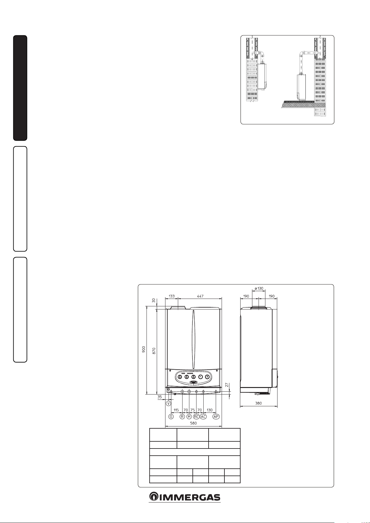
• On/O digital chrono-thermostat (Fig. 1-3).
e chrono-thermostat allows:
- set two room temperature value: one for
daytime (comfort temperature) and one for
night-time (reduced temperature);
- set a weekly program with four daily switch
on and switch o times;
- select the required operating mode from the
various possible alternatives:
- manual operation (with adjustable tempera-
MAINTENANCE TECHNICIAN
ture).
- automatic operation (with set programme).
- forced automatic operation (momentarily
changing the temperature of the automatic
programme).
e chronothermostat is powered by two 1.5V
LR 6 type alkaline batteries.
• ere are two types of Remote Friend Con-
trolV2 (CARV2) (Fig. 1-3) and Mini Digital
Remote Control (Mini CRD) (Fig. 1-4) both
with room chronothermostat functioning.
In addition to the functions described in the
previous point, the control panel enables the
user to keep under control and within reach
all the important information regarding operation of the appliance and the heating system
with the ability to easily act on previously set
parameters, with no need to go to where the appliance is installed. e panel is provided with
self-diagnosis to display any boiler functioning
anomalies. The climate chrono-thermostat
incorporated into the remote panel enables the
system ow temperature to be adjusted to the
actual needs of the room being heated, in order
to obtain the desired room temperature with
extreme precision and therefore with evident
saving in running costs. e remote control is
fed directly by the boiler by means of the same 2
wires used for the transmission of data between
boiler and device.
Important: If the system is subdivided into zones
using the relevant kit. the CARV2 must be used
with its climate thermostat function disabled, i.e.
it must be set to On/O mode. e Mini CRD
cannot be used for plants divided into zones.
Electrical connection of the Remote Friend
ControlV2, chronothermostat On/O (Optional) or Mini . e operations described below
must be performed after having removed the
voltage from the appliance. e eventual ther-
mostat or On/O room chronothermostat must
be connected to terminals 40 and 41 eliminating
jumper X40 (Fig. 3-2). Make sure that the On/
O thermostat contact is of the “clean” type, i.e.
independent of the mains supply; otherwise the
electronic adjustment card would be damaged.
e eventual Remote Friend ControlV2 must be
connected by means of terminals IN+ and IN- to
terminals 42 and 43, eliminating jumper X40
on the terminal board (in the boiler) respecting
polarity (Fig. 3-2). Connection with the wrong
polarity prevents functioning, but without
damaging the Remote Friend ControlV2. Any
Digital Remote Control must be connected to
terminals 40 e 41 eliminating jumper X40 on
the P.C.B. (in the boiler), (Fig. 3-2). e boiler
works with the parameters set on the Remote
Friend ControlV2 only if the boiler main selector is turned to Domestic/Remote Control
( ). e boiler can only be connected to one
remote control.
Important: If the Remote Friend ControlV2,
Mini Digital Remote Control or any other On/O
chronothermostat is used arrange two separate
lines in compliance with current regulations
regarding electrical systems. Boiler pipes must
never be used to earth the electric or telephone
lines. Ensure elimination of this risk before making the boiler electrical connections.
1.9 EXTERNAL PROBE OPTIONAL.
• External temperature probe (Fig. 1-5).
Refer to the relevant instruction sheet for
positioning the external probe.
This sensor can be connected directly to
the boiler electrical system and allows the
max. system delivery temperature to be
automatically decreased when the outside
temperature increases, in order to adjust the
heat supplied to the system according to the
change in external temperature. e external
probe always operates when connected,
regardless of the presence or type of room
chronothermostat used. The correlation
between system delivery temperature and
outside temperature is determined by the
position of the knob on the boiler control
panel according to the curves shown in the
diagram (Fig. 1-6). e external probe electrical
connection must be made on clamps 38 and 39
on the boiler circuit board (Fig. 3-2).
* (Fig. 1-6) Position of the heating temperature
user adjustment.
6
Page 7

1.10 VENTILATION OF THE ROOMS.
In the room in which the boiler is installed it is
necessary that at least as much air ows as that
requested for by normal combustion of the gas
and ventilation of the room. Natural air ow must
take place directly through:
- permanent holes in the walls of the room to
ventilate that go towards the outside;
- ventilation pipes, individual or branched type.
e air used for ventilation must be withdrawn
directly from outside, in an area away from sources of pollution. Natural air ow is also allowed
indirectly by air intake from adjoining rooms. For
further information relative to ventilation of the
rooms follow that envisioned in the regulation.
Evacuation of foul air. In the rooms where the
gas appliances are installed it may also be necessary, as well as the intake of combustion agent air,
to evacuate foul air, with consequent intake of a
further equal amount of clean air. is must be
realised respecting the provisions of the technical
regulations in force.
1.11 EVACUATION OF COMBUSTION
PRODUCTS: FLUE DUCT AND
BRANCHED MULTIPLE FLUES
e European regulation 813/2013 provides that
this boiler can be installed only to replace similar equipment connected to existing branched
multiple ues.
Connection to branched multiple ues.
Fitting the appliances to a branched multiple ues
takes place by means of ue ducts.
In the event of ttings with pre-existing ues,
these must be in safe and ecient status and perfectly clean because the detachment of any waste
from the walls during functioning, could block
the passage of ue gases, thus causing extremely
dangerous situations for the user.
e ue ducts must be connected to the chimney
or ue in the same room in which the appliance
is installed or, at most, in the adjoining room and
must comply with the requirements indicated by
the current technical regulations.
1.12 FLUE EXHAUST CONTROL DEVICE.
Important: it is prohibited to put the fumes
exhaust control device out of order voluntarily.
Every piece of this device must be replaced using
original spare parts if they have deteriorated. In
the case of repeated interventions of the fumes
exhaust control device, check the fumes exhaust
ue and the ventilation of the room in which the
boiler is located.
1.13 SYSTEM FILLING.
Once the boiler is connected, proceed with system lling via the lling valve (Fig. 2-2).
Filling is performed at low speed to ensure
release of air bubbles in the water via the boiler
and heating system vents.
e boiler has a built-in automatic venting valve
on the circulator. Check if the cap is loose. Open
the radiator air vent valves.
Close vent valves only when water is delivered.
Close the lling valve when the boiler pressure
gauge indicates approx. 1.2 bar.
N.B.: During these operations, turn on the circulating pump at intervals by means of the main
selector switch on the control panel.
1.14 GAS SYSTEM STARTUP.
To start up the system, make reference to the
Standard.
In particular, for new gas systems:
- open windows and doors;
- avoid presence of sparks or naked ames;
- bleed all air from pipelines;
- check that the internal system is properly sealed
according to specications.
1.15 STARTUP OF THE BOILER
IGNITION.
To commission the boiler (the operations listed
below must only be performed by a qualied rm
and without any unauthorised persons):
- check that the internal system is properly sealed
according to the specications set forth by
technical regulations in force;
- ensure that the type of gas used corresponds to
boiler settings;
- check that there are external factors that may
cause the formation of fuel pockets;
- switch on the boiler and ensure correct ignition;
- make sure that the gas ow rate and relevant
pressure values comply with those given in the
manual (Par. 3-16);
- check the correct ventilation of the rooms;
- check the existing draught during normal
functioning of the appliance, e.g. a draught
gauge positioned at the exit of the appliance
combustion products;
- check that there is no backow of combustion
products into the room, even during functioning of fans;
- ensure that the safety device is engaged in the
event of gas supply failure and check activation
time;
- check activation of the main circuit-breaker
selector upstream from the boiler and on the
unit.
e boiler must not be started up in the event of
failure to comply with any of the above.
1.16 DOMESTIC HOT WATER BOILER
DEVICE.
e Avio 24 2 ERP boiler is the accumulation
type with a capacity of 45 litres. It contains a large
coiled stainless steel heat exchanger pipe, which
allows to notably reduce hot water production
times. ese boilers built with stainless steel
casing and bottoms, guarantee long duration.
e assembly concepts and welding (T.I.G.) are
implemented to the minimum detail to ensure
maximum reliability.
e lower inspection ange ensures practical
control of the boiler and the coiled heat exchanger and easy internal cleaning.
e domestic water attachments are found on the
ange cover (cold inlet and hot outlet) and also
the magnesium anode holder cap, including the
latter, supplied as standard for internal protection
of the boiler from possible corrosion.
N.B.: every year a skilled technician (e.g. Authorised Aer-sales Service), must check the eciency
of the boiler’s Magnesium Anode. e boiler is
prepared for introduction of the domestic water
re-circulation connection.
INSTALLATORUSER
MAINTENANCE TECHNICIAN
7
Page 8
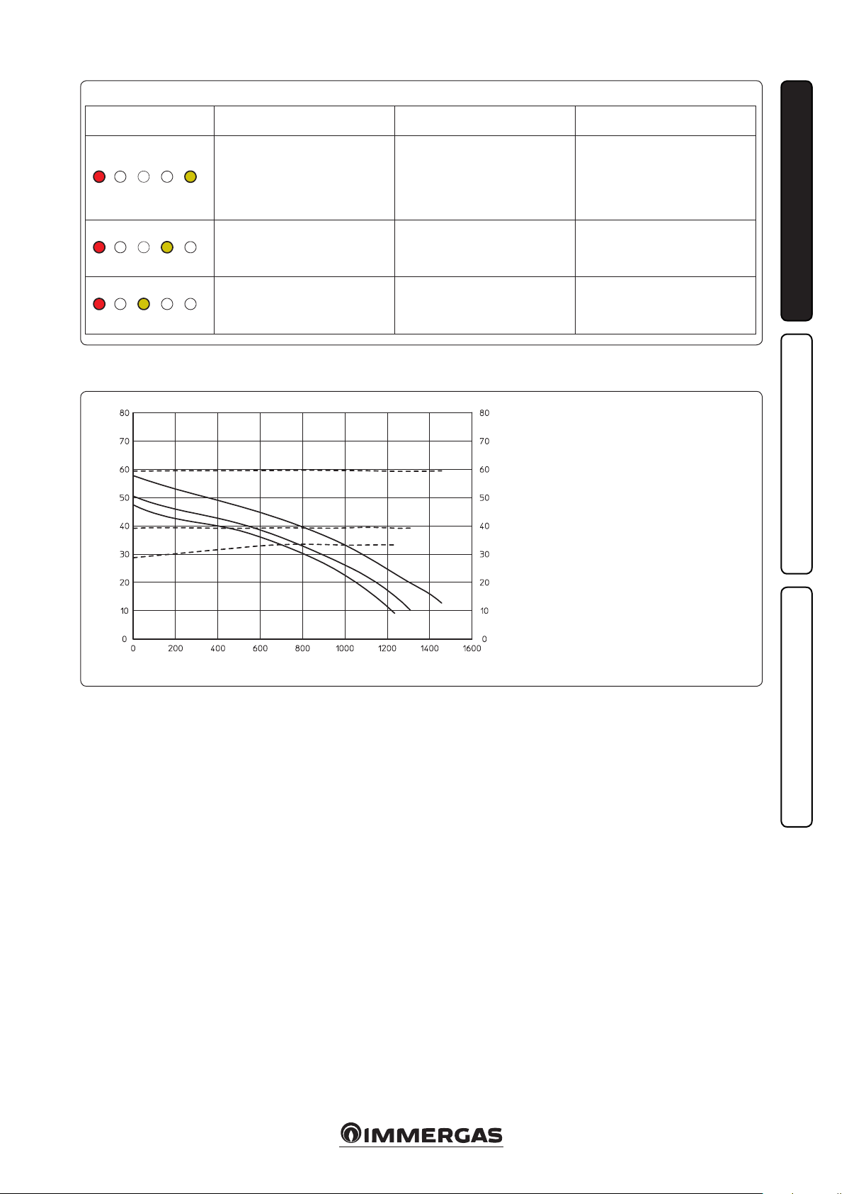
1.17 CIRCULATION PUMP.
e boiler is supplied with circulator tted with
speed regulator.
ese settings are suitable for most systems.
In fact, the pump is equipped with electronic
control to set advanced functions. For proper operation one must select the most suitable type of
operation for the system and select a speed in the
available range, with a focus on energy savings.
By-pass Regulation (part. 21 Fig. 1-10). e
boiler is supplied with by-pass closed by 1.5 turns
with respect to all open.
INSTALLATORUSER
If necessary, the by-pass can be regulated to
system requirements from minimum (by-pass
closed) to maximum (by-pass open). Adjust
using a at head screwdriver, turn clockwise to
open the by-pass; turn anti-clockwise to close it.
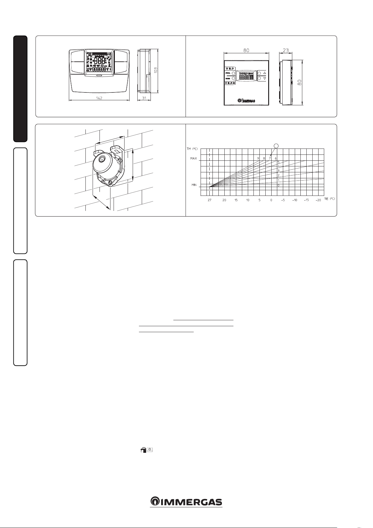
Display of operation status. During normal
operation the status LED (2) is on green, the four
yellow LEDs (3) indicate circulator absorption
according to the following table:
Circulating pump LED Absorption
G Y Y Y Y
On On O O O
G Y Y Y Y
On On On O O
G Y Y Y Y
On On On On O
0 ÷ 25 %
25 ÷ 50 %
50 ÷ 75 %
Circulating pump LED Description
G Y Y Y Y
On On On O O
G Y Y Y Y
On On On On O
G Y Y Y Y
On On On On On
G Y Y Y Y
On On On O On
Constant curve: the circulator operates maintaining constant speed.
Do not use
Constant curve
speed 2
Constant curve
speed 3 (default)
Constant curve
speed 4
1-7
Key:
1 - Function selection button
2 - Green (G) / red (R) LED
3 - 4 yellow LEDs (Y)
Selection button lock. e button has a feature
that locks its operation to prevent accidental
modications, to lock the control panel it is
necessary to press button (1) longer than 10
seconds (during which the current conguration
ashes), the active lock is signalled by all LEDs of
the control panel ashing. To unlock the button
press again longer than 10 seconds.
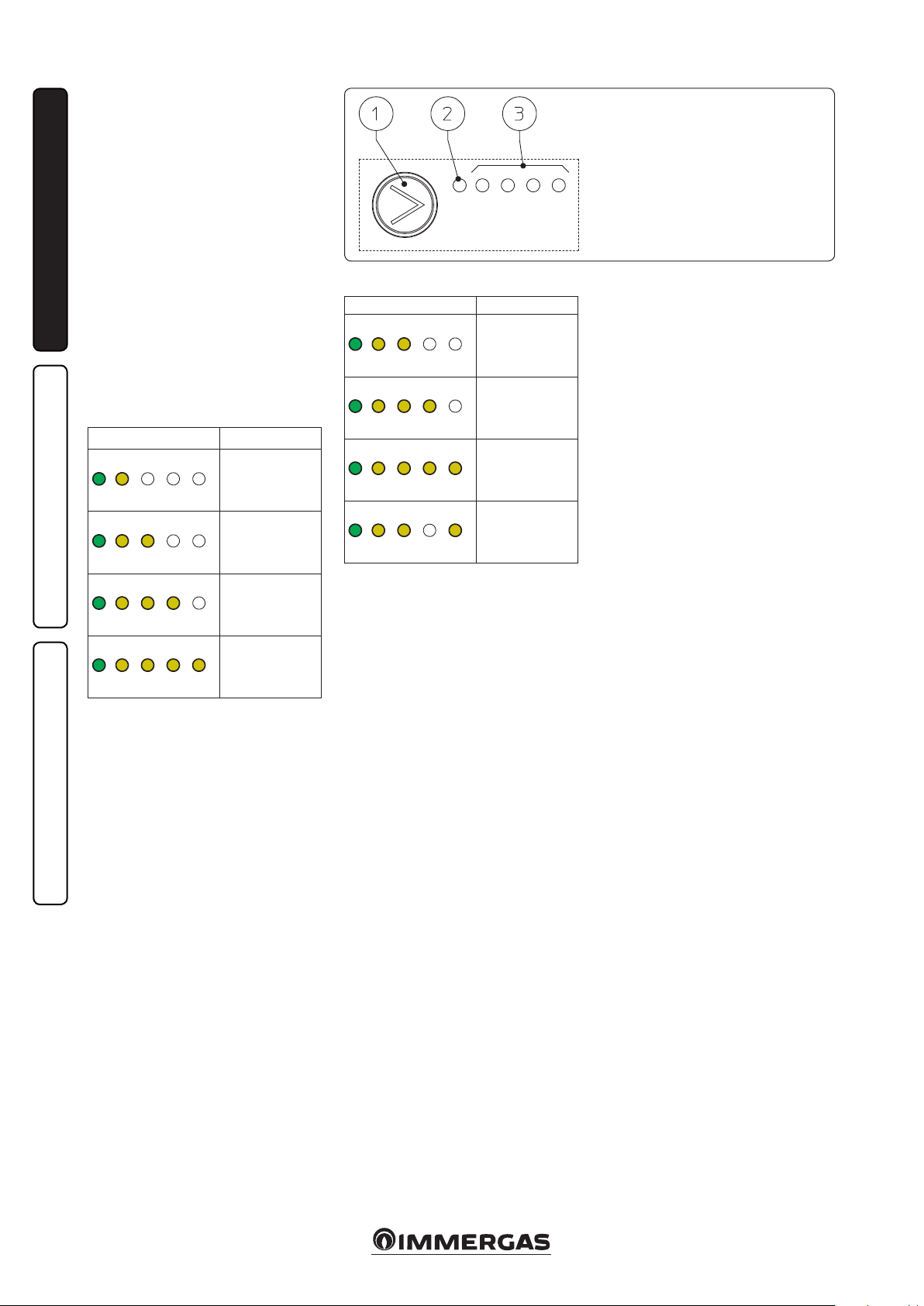
Real time diagnostics: in the event of malfunction the LEDs provide information on the
circulator operation status, see table (Fig. 1-8):
G Y Y Y Y
On On On On On
Selection of operating mode. To see the current
operation mode it is sucient to press button
(1) once.
To change operation mode press the button
for between 2 to 10 seconds until the current
conguration ashing, each time the button is
pressed all possible functions are scrolled cyclically. Aer a few seconds without doing any
operation the circulator memorises the selected
mode and goes back to operation display.
Attention: e circulator has various built-in
MAINTENANCE TECHNICIAN
operation modes, however the constant curve
operation mode must be selected according to
the following table.
75 ÷ 100 %
8
Page 9
1-8
Circulating pump LED
(rst red LED)
R Y Y Y Y
On O O O On
R Y Y Y Y
On O O On O
Description Diagnostics Remedy
Circulator pump blocked
Abnormal situation (the circulator
continues operating).
low power supply voltage
Wait for the circulator to make auto-
The circulator pump cannot restart
automatically due to an anomaly
Voltage o range Check power supply
matic release attempts or manually
release the motor sha acting on the
screw in the centre of the head.
If the anomaly persists replace the
circulator.
INSTALLATORUSER
R Y Y Y Y
On O On O O
Total head available to the plant.
A2
Total head (kPa)
Electrical fault
(Circulator pump blocked)
Capacity (l/h)
e circulator is locked due to power
supply too low or serious malfunction
A4
A3
V4
V2 V3
Check the power supply, if the anomaly
persists replace the circulator
1-9
Key:
V2 = Total head available to the system with
pump at speed 2
V3 = Total head available to the system with
pump at speed 3
V4 = Total head available to the system with
pump at speed 4
A2 = Power absorbed by the pump at speed 2
A3 = Power absorbed by the pump at speed 3
A4 = Power absorbed by the pump at speed 4
Circulator pump absorbed power (W)
1.18 KITS AVAILABLE ON REQUEST.
• Kit of system shuto valves (on request). e
boiler is designed for installation of system
shuto valves to be placed on delivery and
return pipes of the connection assembly. is
kit is particularly useful for maintenance as
it allows the boiler to be drained separately
without having to empty the entire system.
• System zone Kit (on request). If the heating
system is to be divided into several zones (max.
three), in order to interlock them with separate
adjustments and to keep water ow rate high
for each zone, Immergas supplies zone system
kits by request.
• Polyphosphate batching kit (on request). e
polyphosphate dispenser Reduces the formation of lime-scale and preserves the original
heat exchange and domestic hot production
water conditions. e boiler is prepared for
application of the polyphosphate dispenser kit.
e above kits are supplied complete with instructions for assembly and use.
MAINTENANCE TECHNICIAN
9
Page 10

1.19 BOILER COMPONENTS.
INSTALLATORUSER
MAINTENANCE TECHNICIAN
Key:
1 - Fumes hood
2 - primary heat exchanger
3 - Air bleeding valve
4 - Boiler circulation pump
5 - Gas valve
6 - 3-way valve (motorised)
7 - System ller tap
8 - System expansion tank
9 - Domestic water probe
10 - Stainless steel boiler
11 - 3 bar safety valve
12 - System emptying tap
13 - 8 bar safety valve
14 - Boiler emptying cock
15 - Fumes thermostat
16 - Delivery probe
17 - Safety thermostat
18 - Combustion chamber
19 - Ignition and detection plugs
20 - Burner
21 - Adjustable by-pass
1- 10
10
Page 11

INSTRUCTIONS FOR USE
2
AND MAINTENANCE
2.1 CLEANING AND MAINTENANCE.
Attention: to preserve the boiler’s integrity
and keep the safety features, performance and
reliability, which distinguish it, unchanged over
time, you must at least execute maintenance
operations on a yearly basis in compliance with
what is stated in the relative point at “annual
check and maintenance of the appliance”, in
compliance with national, regional, or local
standards in force.
2.2 VENTILATION OF THE ROOMS.
In the room in which the boiler is installed it
is necessary that at least as much air ows as
that requested for by normal combustion of the
gas and ventilation of the room. e provisions
relative to ventilation, the flue ducts and
multiple ues are stated in Par. 1.10 ÷ 1.12. If in
doubt regarding correct ventilation, contact an
authorised company.
2.3 GENERAL WARNINGS
Never expose the suspended boiler to direct
vapours from a cooking surface.
Use of the boiler by unskilled persons or children
is strictly prohibited.
If temporary shutdown of the boiler is required,
proceed as follows:
a) drain the heating system if anti-freeze is not
used;
b) shut-o all electrical, water and gas supplies.
In the case of work or maintenance to structures
near ducting or devices for ue extraction and the
relative accessories, switch o the appliance and
on completion of the operations make sure that
an authorised company veries the eciency of
the ducting or the devices.
Never clean the appliance or connected parts
with easily ammable substances.
Never leave containers or ammable substances
in the same environment as the appliance.
It is prohibited ad dangerous to obstruct the air
intake, even partially, for the ventilation of the
room in which the boiler is installed.
Due to the danger, operation is also prohibited
in the same room as suction devices or the like,
at the same time as the boiler unless there are
additional openings dimensioned in a way to
satisfy the additional requirement for air. For the
dimensioning of these additional openings, refer
to an authorised company.
• Important: the use of components involving
use of electrical power requires some
fundamental rules to be observed such as:
- do not touch the appliance with wet or
moist parts of the body; do not touch when
barefoot;
- never pull electrical cables or leave the
appliance exposed to atmospheric agents
(rain, sunlight, etc.);
- the appliance power cable must not be
replaced by the user;
- if the cable is damaged, switch off the
appliance and solely contact an authorised
company to replace it;
- if the appliance is not to be used for a certain
period, disconnect the main power switch.
N.B.: the temperatures indicated by the display
have a tolerance of +/- 3°C due to environmental
conditions that cannot be blamed on the boiler.
At the end of its service life the appliance must
not be disposed of like normal household waste
nor discarded in the environment, but must be
removed by an authorised company. C ontact the
manufacturer for disposal instructions.
INSTALLATORUSER
2.4 CONTROL PANEL.
2-1
Key:
1 - Flame presence LED
2 - Domestic hot water LED
3 - Heating function LED
4 - Temperature LED – Insucient
circulation anomaly
5 - Temperature LED – Delivery probe
anomaly
6 - Temperature LED – ignition block
7 - Temperature LED – Over-temperature
block
8 - Temperature LED – Fumes thermostat
anomaly
9 - Stand-by-Domestic water / Remote
Control - Domestic water and HeatingReset Selector switch
MAINTENANCE TECHNICIAN
10 - Domestic hot water temperature
selector switch
11 - Heating water temperature selector
switch
12 - Boiler manometer
11
Page 12

2.5 IGNITION OF THE BOILER.
Before ignition make sure the heating system is
lled with water and that the manometer (12)
indicates a pressure of 1÷1,2 bar.
- Open the gas cock upstream from the boiler.
- Turn the master switch (9) taking it to
the Domestic/Remote Friend ControlV2
(CARV2) ( )or Domestic Hot Water
( )position.
N.B.: Once the main selector switch has been
placed (9) on one of these positions, the presence
of voltage is indicated by the switch-on with a
INSTALLATORUSER
xed light of one of the LEDS from 4 to 8, which
indicate the temperature of the output water from
the main heat exchanger.
Important: ashing of one of the LEDs from 4
to 8 indicates that there is an anomaly present,
refer to the successive paragraph.
Functioning of the boiler in domestic water mode
and in heating mode is indicated respectively by
the switch-on of LED 2 or LED 3 with a xed light
(in absence of remote controls).
• Operation with Remote Friend ControlV2
(Optional). With selector switch (9) in position
( ) and Remote Control connected to
the boiler selector switches (10) and (11)
excluded. e boiler adjustment parameters
are set from the control panel of the Remote
Friend ControlV2. Connection to the Remote
Control is indicated by the contemporary xed
switch-on of LEDs 2 and 3 ( ). Also in the
presence of Remote Control the indications of
the temperature and any faults are maintained
on the control panel.
• Operation without Remote Control. With the
selector switch (9) in position ( ) the
heating adjustment selector switch is cut out,
the domestic hot water temperature is regulated
by selector switch (10). With the selector switch
in position ( )the heating adjustment
selector switch (11) is used to regulate the
temperature of radiators, while selector (10)
continues to be used for domestic hot water.
Turn the selector switches in a clockwise
direction to increase the temperature and in
an anti-clockwise direction to decrease it.
From this moment the boiler functions
automatically. With no demand for heat (heating
or domestic hot water production) the boiler
goes to “standby” function, equivalent to the
boiler being powered without presence of
ame (LED corresponding to the ignited boiler
temperature). Each time the boiler lights up, the
relative ame present symbol is displayed by the
green LED 1 ( ).
N.B.: the boiler may start-up automatically if the
anti-freeze function is activated.
2.6 FAULT AND ANOMALY SIGNALS.
e Avio 24 2 ERP boiler signals ant anomaly by
ashing of one of the LEDs from 4 to 8 or LEDs 1
and 2 coupled to LED 7. On any remote controls,
the error code will be displayed using a numerical
code preceeded or followed by the letter E (e.g.
CARV2 = Exx, Mini CRD = xxE).
Flashing LED
Led 6 ( )
Led 7 ( )
MAINTENANCE TECHNICIAN
Led 8 ( )
Led 2 ( )
and 7 ( )
blinking
at the same time
Led 5 ( )
Led 2 ( )
(1) If the shutdown or fault persists, contact an authorised company (e.g. Authorised Technical Aer-Sales Service).
(2) Error codes over 31 are not shown on the CARV2 display.
Error
Code
Anomaly signalled Cause Boiler status / Solution
01 No ignition block
Safety thermostat
02
block (over-temperature)
Flue safety thermo-
03
stat block
Contacts resistance
04
block
Flow probe
05
anomaly
Storage tank probe
12
anomaly
In the event of request of room central heating or domestic hot water production, the boiler does not switch on
within the preset time. If this does not occur within 10
seconds, the boiler remains in stand-by for 30 seconds, try
again and if the second attempt fails it goes into “ignition
block” (ashing LED 6).
During operation, if a fault causes excessive overheating
internally, in the exhaust, or an anomaly occurs in the ame
control section, an overheating block is triggered in the
boiler (LED 7 ashing).
The fume evacuation pipe does not function correctly
(code 03).
is occurs in the case of faults to the safety thermostat
over-temperature).
e board detects an anomaly on the ow probe. e boiler does not start (1).
If the board detects a fault on the storage tank probe.
To eliminate “no ignition block” the
main switch (9) must be temporarily
turned to the Reset position (1).
Warning: the fault may be reset up
to 5 times consecutively, aer which
the function in inhibited for at least
one hour. One attempt is gained every
hour for a maximum of 5 attempts. By
switching the appliance on and o the
5 attempts are re-acquired.
On commissioning or aer extended inactivity it may be necessary to eliminate
the “no ignition block”.
To eliminate the “overheating block” the
main switch (9) must be temporarily
turned to the Reset position (1).
e boiler goes into stand-by for 30
minutes, aer which, if normal working conditions are restored, it re-starts
without having to be reset. In the case
of 3 consecutive blocks, the boiler itself
blocks and it must be reset in order to
re-start (1).
e boiler does not start (1).
e boiler does not start in domestic
hot water mode however, it remains in
heating mode (1).
12
Page 13

Flashing LED
Led 1 ( )
and 7 ( )
blinking
at the same time
Led 4 ( )
Led 2 and 3
blinking
at the same time
( )
(1) If the shutdown or fault persists, contact an authorised company (e.g. Authorised Technical Aer-Sales Service).
(2) Error codes over 31 are not shown on the CARV2 display.
Error
Code
20
27
31
Anomaly signalled Cause Boiler status / Solution
Parasite ame
block
Insucient
circulation
Loss of remote
control
communication
is occurs in the event of a leak on the detection circuit or
anomaly in the ame control unit.
is occurs if there is overheating in the boiler due to
insucient water circulating in the primary circuit; the
causes can be:
- low system circulation; check that no shut-o devices are
closed on the heating circuit and that the system is free of
air (deaerated);
- pump blocked; free the pump.
This occurs if an incompatible remote control is connected, or if communication between the boiler and the
Remote Comando AmicoV2 (CARV2) or digital remote
control (Mini CRD) is lost.
Press the Reset button (1).
Press the Reset button (1).
Try the connection procedure again
by turning the boiler off and turning
the switch (9) to position ( ). If
the CARV2 is still not detected on restarting, the boiler will switch to local
operating mode, i.e. using the controls
on the boiler itself (1) (2).
INSTALLATORUSER
2.7 BOILER SHUTDOWN.
Disconnect the main selector switch (9) taking
it to position “ ” (Leds from 1 to 8 off),
disconnect the external omni-polar switch to the
boiler and close the gas cock upstream from the
appliance. Never leave the boiler switched on if
le unused for prolonged periods.
2.8 RESTORING HEATING SYSTEM PRESSURE.
Periodically check the system water pressure.
e boiler pressure gauge should read a pressure
between 1 and 1.2 bar.
If the pressure falls below 1 bar (with the circuit
cool) restore normal pressure via the valve located
at the bottom of the boiler (Fig. 2-2).
N.B.: close the valve aerwards.
If pressure values reach around 3 bar the safety
valve may be activated.
In this case, remove water from an air vent valve
of a radiator until 1 bar is reached or ask for
assistance from an authorised company.
In the event of frequent pressure drops, contact
a qualied rm for assistance to remove any
system leakage.
2.9 DRAINING THE SYSTEM.
To drain the boiler, use the special drain cock
(Fig. 2-2).
Before draining, ensure that the lling cock is
closed.
2.10 DRAINING THE BOILER.
To drain the boiler, use the special drain cock
(Fig. 2-2).
N.B.: before performing this operation close the
boiler cold water inlet cock and open hot water
cock in the domestic water system in order to
allow water to enter the boiler.
2.11 ANTIFREEZE PROTECTION.
e boiler comes standard with an antifreeze
function that activates the pump and burner
when the system water temperature in the boiler
falls below 4°C.
e antifreeze function is guaranteed if the boiler
is fully operative and not in “block” status, and
is electrically powered with the general switch
positioned on Summer or Winter. To avoid
keeping the system switched on in case of a
prolonged absence, the system must be drained
completely or antifreeze substances added to
the heating system water. In both cases the
boiler domestic water circuit must be drained.
In systems that are drained frequently, lling
must be carried out with suitably treated water
to eliminate hardness that can cause lime-scale.
2.12 CASE CLEANING.
Use damp cloths and neutral detergent to clean
the boiler casing. Never use abrasive or powder
detergents.
2.13 DECOMISSIONING.
In the event of permanent shutdown of the
boiler, contact an authorised rm for the relevant
procedures and also ensure the electrical,
water and fuel supply lines are shut off and
disconnected.
MAINTENANCE TECHNICIAN
BOTTOM VIEW
1 - Boiler drain cock
5
1
2 - Domestic water inlet cock
3 - Gas cock
4 - System drain cock
5 - System lling valve
4
23
2-2
13
Page 14

BOILER COMMISSIONING
3
INITIAL CHECK
To commission the boiler:
- ensure that the type of gas used corresponds to
boiler settings;
- check connection to a 230V-50Hz power
mains, correct L-N polarity and the earthing
connection;
- make sure the heating system is lled with
water and that the manometer indicates a
pressure of 1 - 1.2 bar;
INSTALLATORUSER
- make sure the air valve cap is open and that the
system is well deaerated;
- switch the boiler on and ensure correct ignition;
3.1 HYDRAULIC LAYOUT.
- make sure the gas maximum, medium and
minimum flow rate and pressure values
correspond to those given in the handbook
(Par. 3.16);
- check activation of the safety device in the event
of no gas, as well as the relative activation time;
- check activation of the master switch located
upstream from the boiler and in the boiler;
- check the existing draught during normal
functioning of the appliance, e.g. a draught
gauge positioned at the exit of the appliance
combustion products;
- check that there is no backow of combustion
products into the room, even during
functioning of fans;
- ensure activation of all adjustment devices;
- seal the gas ow rate regulation devices (if
settings are modied);
- ensure production of hot domestic water;
- ensure sealing eciency of water circuits;
- check ventilation and/or aeration of the
installation room where provided.
If any checks/inspection give negative results, do
not start the boiler.
MAINTENANCE TECHNICIAN
Key:
1 - Gas valve
2 - Stainless steel coil for boiler
3 - Magnesium anode
4 - Stainless steel boiler
5 - Air bleeding valve
6 - Burner
7 - Combustion chamber
8 - Primary heat exchanger
9 - Fumes hood
10 - Flue safety thermostat
11 - Delivery probe
12 - Safety thermostat
13 - System expansion tank
14 - Boiler circulating pump
15 - Adjustable by-pass
16 - System drain cock
17 - 3-way valve (motorised)
18 - Domestic water probe
19 - 3 bar safety valve
20 - System lling cock
21 - 8 bar safety valve
22 - Cold water inlet non-return valve
23 - Boiler drain cock
G - Gas supply
AC - Domestic hot water outlet
AF - Domestic cold water inlet
R - System return
M - System delivery
14
3-1
Page 15

3.2 WIRING DIAGRAM.
6
7
3 4
1
2
Key:
A5 - CARV2 interface card
B1 - Delivery probe
B2 - Domestic water probe
B4 - External probe (Optional)
CARV2 - Remote Friend Control
V2
(Optional)
Mini CRD - Mini Digital Remote Control
(Optional)
E1 - Ignition plugs
5
E2 - Igniter sensor
E4 - Safety thermostat
E6 - Fumes thermostat
F1 - Neutral fuse
F2 - Line fuse
M1 - Boiler circulating pump
M30 - 3-way valve
R5 - Domestic water temp. trimmer
R6 - Heating temp. trimmer
INSTALLATORUSER
R10 - Main selector switch
S8 - Gas type selector
S20 - Environment thermostat
T2 - Switch-on transformer
X40 - Environment thermostat jumper
Y1 - Gas valve
Y2 - Gas valve modulator
1 - Primary
2 - Secondary
3 - 230 Vac 50Hz Power supply
4 - 230 Vac 50Hz max 2°aux. output
5 - Area card (Optional)
6 - Heating
7 - Domestic water
Colour code key:
BK - Black
BL - Blue
BR - Brown
G - Green
GY - Grey
G/Y - Yellow/Greene
R - Red
W - White
3-2
Remote controls: the boiler is designed to use
the Remote Friend ControlV2 (CARV2), or as an
alternative to the Mini Digital Remote Control
(Mini CRD) which must be connected to clamps
42 and 43 of connector X9 for the CARV2 (respecting polarity) and clamps 40 and41 of connector
X9 for the Mini CRD on the circuit board and in
both cases eliminating X40.
Environment thermostat (alternative to the Mini
CRD): the boiler is designed to use the Room
ermostat (S20). Connect it to clamps 40 –41
eliminating jumper X40.
Connector X12 is used for automatic inspection
for connection to the personal computer.
3.3 TROUBLESHOOTING. N.B.: maintenance operations must be carried
out by an authorised company (e.g. Authorised
Aer-Sales Technical Assistance Service).
- Smell of gas. Caused by leakage from gas circuit
pipelines. Check sealing eciency of gas intake
circuit.
- Irregular combustion (red or yellow ame).
This may be caused by: a dirty burner, or
blocked boiler lamellar pack.
- Frequent activation of the temperature
overload thermostat. is may be caused by
lack of water in the boiler, insucient water
circulation in the circuit, a blocked circulator
or an anomaly of the boiler adjustment card.
Check via the pressure gauge that values are
within admissible limits. Check that radiator
valves are not all closed.
- e boiler produces condensate. is can be
caused by obstructions of the chimney or ues
with height or section not proportioned to the
boiler. It can also be determined by functioning
at boiler temperatures that are excessively low.
In this case, make the boiler run at higher
temperatures.
- Frequent interventions of the chimney safety
thermostat. is can be caused by obstructions
in the fumes circuit. Check the ue. e ue
may be obstructed or by height or section
not suitable for the boiler. Ventilation may be
insucient (see room ventilation point).
- Presence of air in the system. Check opening
of the special air bleeding cap (Fig. 1-8). Make
sure the system pressure and expansion tank
pre-charge values are within the set limits; the
pre-charge value for the expansion tank must
be 1.0 bar, and system pressure between 1 and
1.2 bar.
- Ignition block and Flue block (Par. 2.6).
- Domestic water probe broken. e boiler does
not have to be emptied in order to replace the
domestic water probe as the probe is not in
direct contact with the domestic hot water
present in the boiler.
MAINTENANCE TECHNICIAN
15
Page 16

SIT 845 gas valve
Key:
1 - Coil
2 - Minimum power adjustment screws
INSTALLATORUSER
3 - Maximum power adjustment nut
4 - Gas valve outlet pressure point
5 - Gas valve inlet pressure point
6 - Protection hood
Circuit board
10 - Line fuse 3.15AF
11 - Neutral fuse 3.15AF
12 - Main selector switch
13 - Domestic water temperature trimmer
14 - RS232 computer interface
15 - Heating temperature trimmer
16 - METHANE L.P.G. gas type selector
3.4 CONVERTING THE BOILER TO OTHER TYPES OF GAS.
If the boiler has to be converted to a dierent gas
type to that specied on the data-plate, request
the relative conversion kit for quick and easy
conversion.
e gas conversion operation must be carried
out by an authorised company (e.g. Authorised
Technical Aer-Sales Service).
To convert to another type of gas the following
operations are required:
- remove the voltage from the appliance;
- replace the main burner injectors, making sure
to insert the special seal rings supplied in the
kit, between the gas manifold and the injectors;
- move jumper 16 (Fig. 3-4) into the correct
position for the type of gas in use (Methane or
L.P.G.);
MAINTENANCE TECHNICIAN
- to access adjustments on the circuit board the
cover must be removed from the dashboard by
loosening the rear screw fasteners;
- apply voltage to the appliance;
- adjust the boiler maximum heat power;
- adjust the boiler minimum heat power;
- adjust (eventually) the heating power;
- seal the gas ow rate devices (if adjusted);
- aer completing conversion, apply the sticker,
present in the conversion kit, near the dataplate. Using an indelible marker pen, cancel
the data relative to the old type of gas.
ese adjustments must be made with reference
to the type of gas used, following that given in
the table (Par. 3.16).
4
1
5
3.5 CHECKS FOLLOWING CONVERSION TO ANOTHER TYPE OF GAS.
Aer making sure that conversion was carried
out with a nozzle of suitable diameter for the
type of gas used and the settings are made at the
correct pressure, check that:
- there is no ame in the combustion chamber
- the burner ame is not too high or low and that
it is stable (does no detatch from burner)
- the pressure testers used for calibration are
perfectly closed and there are no leaks from
the gas circuit.
N.B.: all boiler adjustment operations must be
carried out by a qualied company (e.g. Authorised Aer-sales Service). Burner calibration
must be carried out using a “U” or digital type
dierential pressure gauge, connected to the gas
valve pressure outlet (part. 4 Fig. 3-3), keeping
to the pressure value given in the tables (Par.
3.16) according to the type of gas for which the
boiler is prepared.
3.6 POSSIBLE ADJUSTMENTS OF THE GAS VALVE.
• Adjustment of boiler nominal heat output (Fig.
3-3).
- Turn the domestic hot water selector knob (10
Fig. 2-1) to the maximum functioning position;
- open the domestic hot water cock in order to
prevent modulation intervention;
- adjust the boiler nominal power on the brass
nut (3), keeping to the maximum pressure
values stated in the tables (Par. 3.16) dep ending
on the type of gas;
- by turning in a clockwise direction the heating
potential increases and in an anti-clockwise
direction it decreases.
• Adjust the boiler minimum thermal input (Fig.
3-3).
N.B.: only proceed aer having calibrated the
nominal pressure.
Adjustment of the minimum thermal input is
obtained by operating on the cross plastic screws
3
2
6
(2) on the gas valve maintaining the brass nut
blocked (3);
- disconnect the power supply to the modulating
reel (just disconnect a faston); By turning
the screw in a clockwise direction, the
pressure increases, in an anti-clockwise
direction it decreases. On completion of
calibration, re-apply the power supply to the
modulating reel. e pressure to which the
boiler minimum power must be adjusted,
3-3
must not be lower than that stated in the
tables (Par. 3.16) depending on the type of gas.
N.B.: to adjust the gas valve, remove the plastic
cap (6); aer adjusting, ret the cap and screw.
3.7 PROGRAMMING THE CIRCUIT
BOARD.
e Avio 24 2 ERP boiler is prepared for possible
programming of several operation parameters. By
modifying these parameters as described below, the
boiler can be adapted according to specic needs.
To access the programming phase, proceed as
follows: position the main selector switch on Reset
for a period of time between 15 and 20 seconds
(aer about 10 sec. LEDs 2 and 3 will start to ash at
3-4
the same time. Wait for this to end and re-position
the main selector switch on domestic water and
heating). At his point, re-position the main selector
switch on domestic water-heating.( ).
When the programming phase has been
activated, enter the rst level where it is possible
to choose the parameter to be set.
e latter is indicated by the fast ashing of one
of the LEDs between 1 and 8 (Fig. 2-1).
Selection is made by turning the domestic hot
water temperature selector switch (10). For
association of the LED to the parameter, see the
following table:
List of parameters
Minimum heating power Led 1
Maximum heating power Led 2
Heating switch-on timer Led 3
Heating power output ramp Led 4
Heating switch-on delay on request
from Environmental ermostat,
Mini Digital Remote Control or
Remote Friend Control
Domestic water thermostat/Boiler
hysteresis
Circulating pump functioning Led 7
Functioning gas Led 8
Boiler mode Led 1 and 8
V2
Flashing
LED (fast)
Led 5
Led 6
Once the parameter to be modied has been
selected, conrm by turning the main selector
switch to Reset momentarily until the LED
relative to the parameter switches-off, then
release.
Given the OK for selection, pass to the second
level where it is possible to set the value of the
16
Page 17

parameter selected. e value is indicated by the
slow ashing of one of the LEDs between 1 and
8. e value is selected by rotating the heating
temperature selector switch (11).
Once the value of the parameter to be modied
has been selected, confirm the selection by
momentarily turning the main selector switch
onto Reset momentarily until the LED relative to
the parameter switches o, then release.
Programming mode is exited if no operation is
carried out for 30 seconds or if the main selector
switch is positioned at OFF from the “parameter
setting” level.
For association of the LED to the relative value,
see the following tables:
Heating power. The boiler is produced and
calibrated in the heating phase at nominal power.
It also has electronic modulation that adapts
the boiler potentiality to the eective heating
demand of the house. en the boiler works
normally in a variable gas pressure eld between
the minimum heating power and the maximum
heating power depending on the plants heating.
N.B: the selection of the “Minimum heating
power” and “Maximum heating power”
parameters, in the presence of a heating demand
, allows switch-on of the boiler and power supply
of the modulator with current equal to the value
of the respective selected parameter.
Minimum heating power
(continuous variation)
0% Imax. (Standard setting) Led 1
7% Imax. Led 2
14% Imax.
21% Imax. Led 4
28% Imax. Led 5
35% Imax. Led 6
42% Imax. Led 7
63% Imax. Led 8
Maximum heating power
(continuous variation)
0% Imax. Led 1
11% Imax. Led 2
22% Imax.
33% Imax. Led 4
44% Imax. Led 5
55% Imax. Led 6
88% Imax.
100% Imx. (Standard setting) Led 8
Permanent reduction of the timer. e boiler
has an electronic timing device that prevents the
burner from igniting too oen in the heating
phase. e boiler has a standard supply of a timer
adjusted at 180 seconds.
Flash-
ing LED
(slow)
Led 3
Flash-
ing LED
(slow)
Led 3
Led 7
Heating switch-on timer
(continuous variation)
30 seconds Led 1
55 seconds Led 2
80 seconds Led 3
105 seconds Led 4
130 seconds Led 5
155 seconds Led 6
180 seconds (Standard setting) Led 7
255 seconds Led 8
Heating ramp timing. e boiler distributes he
maximum power set in the previous parameter.
e boiler performs an ignition ramp of about
650 seconds to arrive from minimum power to
nominal heating power.
Heating ramp timer (continuous variation)
65 seconds Led 1
130 seconds Led 2
195 seconds Led 3
390 seconds
455 seconds Led 5
520 seconds Led 6
585 seconds Led 7
650 seconds (Standard setting) Led 8
Heating switch-on delay request from Room
thermostat and Remote Friend ControlV2. e
boiler is set to switch-on immediately aer a
request. In the case of particular plants (e.g. area
plants with motorised thermostatic valves etc.) it
could be necessary to delay switch-on.
Heating switch-on delay request from Room thermostat
and Remote Friend ControlV2
(continuous variation).
0 seconds (Standard setting)
54 seconds Led 2
131 seconds Led 3
180 seconds Led 4
206 seconds Led 5
355 seconds Led 6
400 seconds Led 7
510 seconds Led 8
Domestic water thermostat/Boiler hysterisis.
With the setting of hysteresis 1 the boiler switches
on with a boiling device temperature equal to a
set point at -3°C. With the setting of hysteresis
2 the boiler switches on with a boiling device
temperature equal to a set point at -10°C.
Flash-
ing LED
(slow)
Flash-
ing LED
(slow)
Led 4
Flash-
ing LED
(slow)
Led 1
Domestic water thermostat/
Boiler hysterisis
Hysteresis 1 (Standard setting) Led 1
Hysteresis 1 Led 8
Circulating pump function. Two circulating
pump operational modes
can be selected in heating phase.
In “intermittent” mode it is activated from the
environmental thermostat or from the remote
control, in “continual” mode the circulation
pump functions constantly when the main selector switch (12) is on heating mode.
Circulating pump function
Intermittent (Standard setting) Led 1
Continuous Led 8
Town Gas G110 - Industrial gas. e setting
of this function is used to ad just the boiler in
order to function with gases from the rst family.
Town Gas G110 - Industrial
gas (rst family gas)
O (Standard setting) Led 1
On Led 8
Boiler mode. Establishes if the boiler functions
in instantaneous mode or with boiler (standard
supply).
Boiler mode
Instantaneous (Cannot be
used)
With boiler (Standard setting) Led 8
3.8 AUTOMATIC SLOW IGNITION
FUNCTION WITH TIMED RAMP
DELIVERY.
In the switch-on phase the electronic card carries out an increasing gas delivery ramp (with
pressure values that depend on the type of gas
selected) of preset duration. is avoids every
boiler lighting phase calibration or preparation
operation in any conditions of use.
3.9 “CHIMNEY SWEEP” FUNCTION.
When activated, this function forces the boiler
at max. output for 15 minutes.
IIn this mode all the adjustments are cut out and
only the temperature safety thermostat and the
limit thermostat remain active. To activate the
“Chimney-Sweep” function, press the Reset key
for 8 to 15 seconds in absence of domestic water
and heating requests. Its activation is indicated
by the simultaneous ashing of LEDS (2) and
(3).is function allows the technician to check
the combustion parameters. Aer the checks
deactivate the function, switching the boiler o
and then on again.
Flash-
ing LED
(slow)
Flash-
ing LED
(slow)
Flash-
ing LED
(slow)
Flash-
ing LED
(slow)
Led 1
INSTALLATORUSER
MAINTENANCE TECHNICIAN
17
Page 18

3.10 PUMP ANTIBLOCK FUNCTION.
e boiler has a function that starts the pump
once every 24 hours for the duration of 30
seconds in order to reduce the risk of the pump
becoming blocked due to prolonged inactivity.
3.11 THREEWAY ANTIBLOCK SYSTEM.
Both in “domestic” and in “domestic-heating”
phase the boiler is equipped with a function that
starts the three-way motorized group 24 hours
aer it was last in operation, running it for a
full cycle so as to reduce the risk of the threeway group becoming blocked due to prolonged
INSTALLATORUSER
inactivity.
3.12 RADIATOR ANTIFREEZE
FUNCTION.
If the system return water is below 4°C, the boiler
starts up until reaching 42°C.
3.13 ELECTRONIC CARD PERIODICAL
SELFCHECK.
During operation in heating mode or with boiler
in standby, the function activates every 18 hours
aer the last boiler check/power supply. In case
of operation in domestic circuit mode the selfcheck starts within 10 minutes aer the end of
the drawing in progress, for a length of approx.
10 seconds.
N.B.: During self-check, the boiler remains o,
including signalling.
- fumes pressure switch.
- Check integrity of the boiler Magnesium anode.
- Check the condition and integrity of the
electrical system and in particular:
- electrical power cables must be inside the
whipping;
- there must be no traces of blackening or
burning.
N.B.: in addition to yearly maintenance, the thermal system must also be checked, with frequency
and procedures that comply with the provisions
of the technical regulations in force.
3.15 CASING REMOVAL.
To facilitate boiler maintenance the casing can be
completely removed as follows (Fig. 3-5):
- Disassemble the lower cover by removing the
two relevant screws (1).
- Unscrew the two screw fasteners on the
dashboard and open it making it pivot.
- Unscrew the 2 xing screws (2) on the casing.
- Unhook the lower part of the casing as
described in the gure.
- Pull the casing (4) forwards and up at the same
time (see gure) to detach it from the upper
hooks.
3.14 YEARLY APPLIANCE CHECK AND MAINTENANCE.
e following checks and maintenance should
be performed at least once a year.
- Clean the ue side of the heat exchanger.
- Clean the main burner.
- Visually check the fume hood for deterioration
or corrosion.
- Check correct lighting and operation.
- Ensure correct calibration of the burner in
domestic water and heating phases.
- Check correct operation of control and
adjustment devices and in particular:
- intervention of electrical main electrical
switch on boiler;
- system control thermostat intervention;;
- domestic water control thermostat
intervention
- Check that the internal system is properly
MAINTENANCE TECHNICIAN
sealed according to specications.
- Check intervention of the device against no gas
ionization ame control:
- Intervention time must be less than 10 seconds.
- Visually check for water leaks or oxidation
from/on connections.
- Visually check that the water safety drain valve
is not blocked.
- Check that, aer discharging system pressure
and bringing it to zero (read on boiler pressure
gauge), the expansion tank charge is at 1.0 bar.
- Check that the system static pressure (with
system cold and aer relling the system by
means of the ller cock) is between 1 and 1.2
bar.
- Check visually that the safety and control
devices have not been tampered with and/or
shorted, in particular
- temperature safety thermostat;
1
2
3-5
18
Page 19

3.16 VARIABLE HEAT POWER.
N.B.: Gas flow rates refer to heating power
below a temperature of15°C and at a pressure
of 1013 mbar.
Burner pressure values refer to use of gas at 15°C.
MAX.
MIN CEN.
HEAT.
MIN
D.H.W.
HEAT
POWER
(kW) (kcal/h) (m3/h) (mbar) (mm H2O) (kg/h) (mbar) (mm H2O) (kg/h) (mbar) (mm H2O)
23,7 20382 2,77 13,30 135,6 2,07 27,80 283,5 2,04 35,80 365,1
10,4 8944 1,27 3,00 30,6 0,95 7,12 72,6 0,93 8,38 85,4
9,5 8170 1,17 2,50 25,5 0,87 5,50 56,1 0,86 6,93 70,7
HEAT
POWER
GAS FLOW RATE
BURNER
METHANE (G20) BUTANE (G30) PROPANE (G31)
NOZZLE
PRESSURE BURNER
GAS FLOW RATE
BURNER
NOZZLE
PRESSURE BURNER
GAS FLOW RATE
BURNER
PRESSURE BURNER
NOZZLE
INSTALLATORUSER
3.17 COMBUSTION PARAMETERS.
G20 G30 G31
Gas nozzle diameter mm 1,30 0,79 0,79
Supply pressure mbar (mm H2O) 20 (204) 29 (296) 37 (377)
Flue ow rate at nominal heat output kg/h 73 70 72
Flue ow rate at minimum heat output kg/h 57 54 56
CO2 at Q. Nom./Min. % 5,00 / 2,60 6,10 / 3,20 5,90 / 3,10
CO at 0% of O2 at Q. Nom./Min. ppm 55 / 45 109 / 59 59 / 50
NOX at 0% of O2 at Q. Nom./Min. ppm 177 / 81 279 / 115 240 / 108
Flue temperature at nominal heat output °C 101 106 104
Flue temperature at minimum heat output °C 74 77 76
Combustion parameters: measuring conditions
of useful eciency (ow temperature/return
temperature= 80/60 °C), ambient temperature
reference = 15°C.
MAINTENANCE TECHNICIAN
19
Page 20

3.18 TECHNICAL DATA.
Nominal heating power kW (kcal/h) 26,2 (22546)
Central heating minimum heat output kW (kcal/h) 12,0 (10341)
Domestic hot water minimum heat output kW (kcal/h) 11,0 (9500)
Nominal heating power (useful) kW (kcal/h) 23,7 (20382)
Central heating minimum heat output (useful) kW (kcal/h) 10,4 (8944)
Domestic hot water minimum heat output (useful) kW (kcal/h) 9,5 (8170)
* Useful thermal eciency at nominal output % 90,4
* Useful thermal eciency at 30% nominal output % 86,5
Heat loss at case with burner On/O % 2,40 / 0,57
INSTALLATORUSER
Heat loss at ue with burner On/O % 7,20 / 0,43
Heating circuit max. working pressure bar 3
Heating circuit max. working temperature °C 90
Adjustable heating temperature °C 35 - 85
Total volume system heating expansion tank l 7,7
Heating expansion tank pre-charge bar 1,0
Total volume of DHW expansion vessel l 1,2
DHW expansion vessel factory-set pressure bar 3,5
Generator water capacity l 3,6
Head available with ow rate 1000/h kPa (m H2O) 26,2 (2,7)
Hot water production available heat output kW (kcal/h) 23,7 (20382)
Domestic hot water adjustable temperature °C 20 - 60
Domestic circuit min. pressure (dynamic) bar 0,3
Domestic circuit max. working pressure bar 8,0
Specic capacity (∆T 30°C) l/min 13,5
Weight of full boiler kg 53,6
Weight of empty boiler kg 50,0
Electric attachment V/Hz 230 / 50
Nominal absorption A 0,4
Installed electric power W 45
Power absorbed by circulation pump W 33
Value EEI - ≤ 0,20 - Part. 3
Equipment electrical system protection - IPX4D
NOX class - 3
NOX weighted mg/kWh 146
CO weighted mg/kWh 49
Type of appliance B11
Category II2H3+
BS
- e data relevant to domestic hot water perfor-
mance refer to a dynamic inlet pressure of 2 bar
and an inlet temperature of 15°C; the values are
measured directly at the boiler outlet considering that to obtain the data declared mixing with
cold water is necessary.
MAINTENANCE TECHNICIAN
- * Eciencies refer to the lower heating value
20
Page 21

3.19 DATA PLATE KEY.
Md Cod. Md
Sr N° CHK Cod. PIN
Type
Qnw/Qn min. Qnw/Qn max.
Pn min. Pn max.
PMS PMW D TM
NOx Class
Note: the technical data are shown on the boiler data plate
ENG
Md
Cod. Md
Sr N°
CHK
Cod. PIN
Typ e
Qnw min.
Qn min.
Qnw max.
Qn max.
Pn min.
Pn max.
PMS
PMW
D
TM
NOx Class
Model
Model code
Serial Number
Check
PIN code
Type of installation (ref. CEN TR 1749)
Minimum heating capacity (domestic)
Minimum heating capacity (heating)
Maximum heating capacity (domestic)
Maximum heating capacity (heating)
Minimum heat output
Maximum heat output
Maximum pressure (system)
Maximum pressure (domestic)
Specic ow rate
Maximum working temperature
Nox Class
21
Page 22

3.20 TECHNICAL PARAMETERS FOR COMBINATION BOILERS IN COMPLIANCE WITH REGULATION 813/2013.
Eciencies in the following tables refer to the gross caloric value.
Model/s: Avio 24 2 ErP
Condensing Boilers: NO
Low temperature boiler: NO
Boiler type B1: YES
Co-generation appliance for central heating: NO Fitted with supplementary heating system: NO
Mixed heating appliance: YES
Element Symbol Va lu e Unit Element Symbol Val ue Unit
Nominal heat output P
n
24 kW
Seasonal energy eciency of central
heating
η
s
75 %
For central heating only and combination boilers: useful heat output For central heating only and combination boilers: useful eciency
At nominal heat output in high tempera-
ture mode (*)
At 30% of nominal heat output in a low
temperature mode (**)
P
P
4
1
23,7 kW
6,8 kW
At nominal heat output in high temperature mode (*)
At 30% of nominal heat output in a low
temperature mode (**)
η
η
4
1
81,4 %
77,9 %
Auxiliary electricity consumption Other items
At full load el
At partial load el
In standby mode P
0,014 kW Heat loss in standby P
max
0,014 kW Ignition burner energy consumption P
min
0,003 kW Emissions of nitrogen oxides NO
SB
stby
ign
X
0,113 kW
0,000 kW
132
For mixed central heating appliances
Stated load prole XL Domestic hot water production eciency η
Daily electrical power consumption Q
0,163 kWh Daily gas consumption Q
elec
WH
fuel
75 %
26,874 kWh
Contact information IMMERGAS S.p.A. VIA CISA LIGURE, 95 - 42041 BRESCELLO (RE) ITALY
(*) High temperature mode means 60°C on return and 80°C on ow.
(**) Low temperature mode for condensation Boilers means 30°C , for low temperature boilers 37°C and for other appliances 50°C of return temperature.
mg /
kWh
3.21 PRODUCT FICHE IN COMPLIANCE WITH REGULATION 811/2013.
Annual energy consumption for the heating function (QHE) 91,3 GJ
Annual electricity consumption for the domestic hot water function
(AEC)
AVIO 24 2 ERP
Annual fuel consumption for the domestic hot water function (AFC) 20 GJ
Seasonal space heating energy eciency (ηs) 75 %
XL
++
A
+
A
A
B
C
C
D
E
F
G
D
E
F
G
A
B
C
B
Water heating energy eciency ( ηwh) 75 %
For proper installation of the appliance refer to chapter 1 of this booklet (for the installer)
and current installation regulations. For proper maintenance refer to chapter 3 of this
booklet (for the maintenance technician) and adhere to the frequencies and methods
set out herein.
24
59 dB
kW
Parameter value
36 kWh
2015 811/2013
22
Page 23

3.22 PARAMETERS FOR FILLING IN THE PACKAGE FICHE.
In case you should wish to install an assembly,
starting from the Avio 24 2 ErP boiler, use the
assembly charts in g. 3-8 and 3-11.
For correctly lling in, enter the gures shown in
tables g. 3-6 and 3-9 (as shown in the facsimile
package che g. 3-7 and 3-10) .
e remaining values must be obtained from
the technical data sheets of the products used
Facsimile for lling in the package che for preferential boiler space heaters.
Seasonal space heating energy efciency of boiler
to make up the assembly (e.g. solar devices, integration heat pumps, temperature controllers).
Use sheet fig. 3-8 for “assemblies” related to
the heating function (e.g.: boiler + temperature
controller).
Use sheet g. 3-11 for “assemblies” related to the
domestic hot water function (e.g.: boiler + solar
thermal system).
1
‘I’
%
Temperature control
From che of
temperature control
Supplementary boiler
From che of boiler
Solar contribution
From che of solar device
Collector size
(in m2)
( ‘III’ x + ‘IV’ x ) x (0.9 x ( / 100) x =
Supplementary heat pump
From che of heat pump
Solar contribution and Supplementary heat pump
Select smaller value
Seasonal space heating energy efciency of package
Class I = 1 %, Class II = 2 %,
Class III = 1.5 %, Class IV = 2 %,
Class V = 3 %, Class VI = 4 %,
Class VII = 3.5 %, Class VIII = 5 %
Seasonal space heating energy efciency
( - ‘I’ ) x 0.1 =
Tank volume
(in m3)
0.5 x OR 0.5 x =
Collector efciency
Seasonal space heating energy efciency
(in %)
( - ‘I’ ) x ‘II’ =
4 5
(in %)
(in %)
Tank
rating
A* = 0.95, A = 0.91,
B = 0.86, C = 0.83,
D-G = 0.81
+
±
+
+
-
2
%
3
%
4
%
5
%
6
%
7
%
Seasonal space heating energy efciency class of package
+++
++
G F E D C B A A
< 30 % ≥ 30 % ≥ 34 % ≥ 36 % ≥ 75 % ≥ 82 % ≥ 90 % ≥ 98 % ≥ 125 %≥ 150 %
Boiler and supplementary heat pump installed with low temperature heat emitters at 35°C?
From che of heat pump
The energy efciency of the package of products provided far in this che may not correspond to
its actual energy efciency once installed in a building, as the efciency is inuenced by further
factors such as heal loss in the distribution system and the dimensioning of the products in relation to building size and characteristics.
7
+ ( 50 x ‘II’ ) =
+
A
A
%
23
3-6
Page 24

Parameters for lling in the assembly chart.
Parameter Avio 24 2 ErP
‘I’ 75
‘II’ *
‘III’ 1,11
‘IV’ 0,43
* to be established by means of table 5 of Regulation 811/2013 in case of “assembly” including a heat
pump to integrate the boiler. In this case the boiler must be considered as the main appliance of the
assembly.
Room heating system package che.
Seasonal space heating energy efciency of boiler
1
___
3-7
%
Temperature control
From che of
temperature control
Supplementary boiler
From che of boiler
Solar contribution
From che of solar device
Collector size
(in m2)
( ___ x + ___ x ) x (0.9 x ( / 100) x =
Supplementary heat pump
From che of heat pump
Solar contribution and Supplementary heat pump
Select smaller value
Seasonal space heating energy efciency of package
Class I = 1 %, Class II = 2 %,
Class III = 1.5 %, Class IV = 2 %,
Class V = 3 %, Class VI = 4 %,
Class VII = 3.5 %, Class VIII = 5 %
Seasonal space heating energy efciency
( - ___ ) x 0.1 =
Tank volume
(in m3)
0.5 x OR 0.5 x =
Collector efciency
Seasonal space heating energy efciency
(in %)
( - ___ ) x ___ =
4 5
(in %)
(in %)
Tank
rating
A* = 0.95, A = 0.91,
B = 0.86, C = 0.83,
D-G = 0.81
+
±
+
+
-
2
%
3
%
4
%
5
%
6
%
7
%
Seasonal space heating energy efciency class of package
+++
++
G F E D C B A A
< 30 % ≥ 30 % ≥ 34 % ≥ 36 % ≥ 75 % ≥ 82 % ≥ 90 % ≥ 98 % ≥ 125 %≥ 150 %
Boiler and supplementary heat pump installed with low temperature heat emitters at 35°C?
From che of heat pump
The energy efciency of the package of products provided far in this che may not correspond to
its actual energy efciency once installed in a building, as the efciency is inuenced by further
factors such as heal loss in the distribution system and the dimensioning of the products in relation to building size and characteristics.
7
+ ( 50 x ___ ) =
24
+
A
A
%
3-8
Page 25

Facsimile for lling in domestic hot water production system package che.
Water heating energy efciency of combination heater
Declared load prole:
Solar contribution
From che of solar device
( 1,1 x ‘I’ - 10 % ) x ‘II’ - ‘III’ - ‘I’ =
Water heating energy efciency of package under average climate
Water heating energy efciency class of package under average climate
G F E D C B A A
M
L
XL
XXL
< 27 %
< 27 %
< 27 %
< 28 %
≥ 27 %
≥ 27 %
≥ 27 %
≥ 28 %
≥ 30 %
≥ 30 %
≥ 30 %
≥ 32 %
Auxiliary electricity
≥ 33 %
≥ 36 %
≥ 34 %
≥ 37 %
≥ 35 %
≥ 38 %
≥ 36 %
≥ 40 %
≥ 39 %
≥ 50 %
≥ 55 %
≥ 60 %
≥ 65 %
≥ 75 %
≥ 80 %
≥ 85 %
+
A
≥ 100 %
≥ 115 %
≥ 123 %
≥ 131 %
+
++
A
≥ 130 %
≥ 150 %
≥ 160 %
≥ 170 %
1
‘I’
2
3
+++
≥ 163 %
≥ 188 %
≥ 200 %
≥ 213 %
%
%
%
Water heating energy efciency under colder and warmer climate conditions
3 2
Colder: - 0.2 x =
3 2
Warmer: + 0.4 x =
The energy efciency of the package of products provided far in this che may not correspond to
its actual energy efciency once installed in a building, as the efciency is inuenced by further
factors such as heat loss in the distribution system and the dimensioning of the products in relation to building size and characteristics.
%
%
25
3-9
Page 26

Parameters for lling in DHW package assembly chart.
Parameter Avio 24 2 ErP
‘I’ 75
‘II’ *
‘III’ *
* to be determined according to Regulation 811/2013 and transient calculation methods
as per Notice of the European Community no. 207/2014.
Domestic hot water production system package che.
3-10
Water heating energy efciency of combination heater
Declared load prole:
Solar contribution
From che of solar device
( 1,1 x ___ - 10 % ) x ____ - ____ - ____ =
Water heating energy efciency of package under average climate
Water heating energy efciency class of package under average climate
G F E D C B A A
M
L
XL
XXL
< 27 %
< 27 %
< 27 %
< 28 %
≥ 27 %
≥ 27 %
≥ 27 %
≥ 28 %
≥ 30 %
≥ 30 %
≥ 30 %
≥ 32 %
Auxiliary electricity
≥ 33 %
≥ 36 %
≥ 34 %
≥ 37 %
≥ 35 %
≥ 38 %
≥ 36 %
≥ 40 %
≥ 39 %
≥ 50 %
≥ 55 %
≥ 60 %
≥ 65 %
≥ 75 %
≥ 80 %
≥ 85 %
+
A
≥ 100 %
≥ 115 %
≥ 123 %
≥ 131 %
+
++
A
≥ 130 %
≥ 150 %
≥ 160 %
≥ 170 %
1
___
2
3
+++
≥ 163 %
≥ 188 %
≥ 200 %
≥ 213 %
%
%
%
Water heating energy efciency under colder and warmer climate conditions
3 2
Colder: - 0.2 x =
3 2
Warmer: + 0.4 x =
The energy efciency of the package of products provided far in this che may not correspond to
its actual energy efciency once installed in a building, as the efciency is inuenced by further
factors such as heat loss in the distribution system and the dimensioning of the products in relation to building size and characteristics.
%
%
26
3-11
Page 27

Page 28

immergas.com
Immergas S.p.A.
42041 Brescello (RE) - Italy
Tel. 0522.689011
Fax 0522.680617
Certied company ISO 9001
is instruction booklet is made of ecological paper Cod. 1.038455ENG - rev. ST.002233/003 - 04/18 - Irlandese per IRLANDA (IE)
 Loading...