

Immergas AUDAX TOP ErP, AUDAX TOP 6 ErP, AUDAX TOP 8 ErP, AUDAX TOP 12 ErP, AUDAX TOP 18 ErP Series Manual
...Page 1
HEAT PUMPS
voltar.com.ua
voltar.com.ua
voltar.com.ua
voltar.com.ua
voltar.com.ua
voltar.com.ua
voltar.com.ua
AUDAX TOP ErP
AND INTEGRATED
SYSTEMS
with reversible inverter mono-
phase and three-phase air-
water Heat Pumps
voltar.com.ua
voltar.com.ua
voltar.com.ua
voltar.com.ua
voltar.com.ua
voltar.com.ua
voltar.com.ua
voltar.com.ua
voltar.com.ua
voltar.com.ua
voltar.com.ua
Page 2

voltar.com.ua
voltar.com.ua
voltar.com.ua
voltar.com.ua
voltar.com.ua
voltar.com.ua
voltar.com.ua
voltar.com.ua
voltar.com.ua
voltar.com.ua
voltar.com.ua
voltar.com.ua
voltar.com.ua
voltar.com.ua
voltar.com.ua
voltar.com.ua
voltar.com.ua
voltar.com.ua
Page 3

voltar.com.ua
voltar.com.ua
voltar.com.ua
INDEX
MAIN INDEX
1 AUDAX TOP ErP DESCRIPTION .........................................................................................................................................................4
2 AUDAX TOP 6 8 12 ErP FEATURES MONOPHASE ..................................................................................................................5
3 AUDAX TOP 16 18 21 ErP FEATURES THREEPHASE ..............................................................................................................6
4 INTEGRATED SYSTEM FOR AIR CONDITIONING AND D.H.W. PRODUCTION .................................................................. 7
5 HEAT ADJUSTMENT WITH AUDAX TOP ERP CONTROL PANEL IN STANDALONE APPLICATIONS (SETTING AND
OPERATING LOGIC) .............................................................................................................................................................................. 9
6 AUDAX TOP ErP DIMENSIONS AND CONNECTIONS ................................................................................................................21
7 AUDAX TOP ErP MINIMUM INSTALLATION DISTANCES ......................................................................................................... 23
8 AUDAX TOP ErP HYDRAULIC CIRCUIT COMPONENTS ...........................................................................................................25
9 AUDAX TOP ErP OPERATING LIMITS AND ANTIFREEZE FUNCTION ................................................................................... 28
10 AUDAX TOP 6 ErP TECHNICAL DATA .............................................................................................................................................30
11 PRODUCT FICHE REGULATION 811/2013 AUDAX TOP 6 ErP .................................................................................................31
12 AUDAX TOP 6 ERP “POWER” AND “COP” CENTRAL HEATING / “EER” COOLING ............................................................. 32
13 GRAPH OF AUDAX TOP 6 ErP PUMP FLOW RATE/HEAD ...........................................................................................................34
14 AUDAX TOP 8 ErP TECHNICAL DATA ............................................................................................................................................. 35
15 PRODUCT FICHE REGULATION 811/2013 AUDAX TOP 8 ErP.................................................................................................36
16 AUDAX TOP 8 ERP “POWER” AND “COP” CENTRAL HEATING / “EER” COOLING ............................................................. 37
17 GRAPH OF AUDAX TOP 8 ErP PUMP FLOW RATE/HEAD ...........................................................................................................39
18 AUDAX TOP 12 ERP TECHNICAL DATA .......................................................................................................................................... 40
19 PRODUCT FICHE REGULATION 811/2013 AUDAX TOP 12 ErP ...............................................................................................41
20 AUDAX TOP 12 ERP “POWER” AND “COP” CENTRAL HEATING / “EER” COOLING ........................................................... 42
21 GRAPH OF AUDAX TOP 12 ErP PUMP FLOW RATE/HEAD .........................................................................................................44
22 AUDAX TOP 16 ErP TECHNICAL DATA ...........................................................................................................................................45
23 PRODUCT FICHE REGULATION 811/2013 AUDAX TOP 16 ErP ...............................................................................................46
24 AUDAX TOP 16 ERP “POWER” AND “COP” CENTRAL HEATING / “EER” COOLING ........................................................... 47
25 GRAPH OF AUDAX TOP 16 ErP PUMP FLOW RATE/HEAD .........................................................................................................49
26 AUDAX TOP 18 ErP TECHNICAL DATA ...........................................................................................................................................50
27 PRODUCT FICHE REGULATION 811/2013 AUDAX TOP 18 ErP ...............................................................................................51
28 AUDAX TOP 18 ERP “POWER” AND “COP” CENTRAL HEATING / “EER” COOLING ........................................................... 52
29 GRAPH OF AUDAX TOP 18 ErP PUMP FLOW RATE/HEAD .........................................................................................................54
30 AUDAX TOP 21 ErP TECHNICAL DATA ...........................................................................................................................................55
31 PRODUCT FICHE REGULATION 811/2013 AUDAX TOP 21 ErP ...............................................................................................56
32 AUDAX TOP 21 ERP “POWER” AND “COP” CENTRAL HEATING / “EER” COOLING ........................................................... 57
33 GRAPH OF AUDAX TOP 21 ErP PUMP FLOW RATE/HEAD .........................................................................................................59
34 AUDAX TOP 6 8 12 16 ErP P.C.B. .................................................................................................................................................. 60
35 AUDAX TOP 6 8 12 16 ErP CONTROL DIAGRAM .................................................................................................................... 63
36 AUDAX TOP 6 8 12 16 ErP TERMINAL BLOCK ELECTRICAL CONNECTIONS ................................................................ 64
37 AUDAX TOP 18 21 ErP P.C.B. ............................................................................................................................................................65
38 AUDAX TOP 18 21 ErP CONTROL DIAGRAM ..............................................................................................................................66
39 AUDAX TOP 18 21 ErP TERMINAL BLOCK ELECTRICAL CONNECTIONS ...........................................................................67
40 ELECTRIC CONNECTION CABLES FEATURES ............................................................................................................................ 68
41 SYSTEM MANAGER ............................................................................................................................................................................. 69
42 ZONE REMOTE CONTROL ............................................................................................................................................................... 76
43 ROOM TEMPERATURE/HUMIDITY SENSOR ................................................................................................................................ 76
44 EXPANSION BOARD FOR ZONE MANAGEMENT ........................................................................................................................76
45 SYSTEM DISTRIBUTION KIT ............................................................................................................................................................ 77
46 DEHUMIDIFIER ................................................................................................................................................................................... 81
47 INTRODUCTION WITH COMMENTARY TO INTEGRATED SYSTEMS: MAIN APPLICATIONS ...........................................85
48
DIAGRAM AUDAX TOP ERP AND 2 LOW TEMPERATURE ZONES+ SOLAR HEATING FOR D.H.W. PRODUCTION + MANAGER
49 DIAGRAM AUDAX TOP ErP + CONTROL PANEL TO CONTROL THE ROOM + SOLAR PACK ............................................ 90
50 DIAGRAM AUDAX TOP ErP AIR CONDITIONING ONLY + BOILER PLUS + 2 LOW TEMPERATURE ZONES AND
1 DIRECT ZONE + SOLAR HEATING FOR D.H.W. PRODUCTION + SYSTEM MANAGER ...................................................92
51 DIAGRAM AUDAX TOP ErP + BOILER WITH 1 HIGH TEMPERATURE ZONE + 2 LOW TEMPERATURE ZONES
+ SOLAR HEATING FOR DHW + SYSTEM MANAGER ..................................................................................................................94
52 DIAGRAM AUDAX TOP ErP + PLUS BOILER AND 2 LOW TEMPERATURE ZONES + STORAGE TANK UNIT FOR D.H.W.
PRODUCTION + SYSTEM MANAGER.............................................................................................................................................. 96
53
DIAGRAM AUDAX TOP ERP AIR CONDITIONING ONLY + BOILER WITH INTEGRATED STORAGE TANK UNIT + SOLAR
HEATING FOR D.H.W. PRODUCTION, SEPARATE CENTRAL HEATING/COOLING SYSTEM + SYSTEM MANAGER
54 DIAGRAM AUDAX TOP ErP IN CASCADE AIR CONDITIONING ONLY + HIGH POWER BOILER + THERMAL
FLYWHEEL AND MIXED ZONE + SOLAR HEATING FOR D.H.W. PRODUCTION + SYSTEM MANAGER ...................... 100
55 DIAGRAM AUDAX TOP ErP + BOILER AND 2 LOW TEMPERATURE ZONES + SOLAR HEATING FOR D.H.W.
PRODUCTION AND CENTRAL HEATING + SYSTEM MANAGER ........................................................................................... 102
56 OPTIONAL WHICH CAN BE COUPLED .......................................................................................................................................104
57 MAIN INERTIAL STORAGE TANK TECHNICAL FEATURES ..................................................................................................... 107
voltar.com.ua
voltar.com.ua
voltar.com.ua
voltar.com.ua
voltar.com.ua
voltar.com.ua
voltar.com.ua
voltar.com.ua
voltar.com.ua
voltar.com.ua
voltar.com.ua
...88
voltar.com.ua
.......................98
voltar.com.ua
voltar.com.ua
3
voltar.com.ua
Page 4
voltar.com.ua
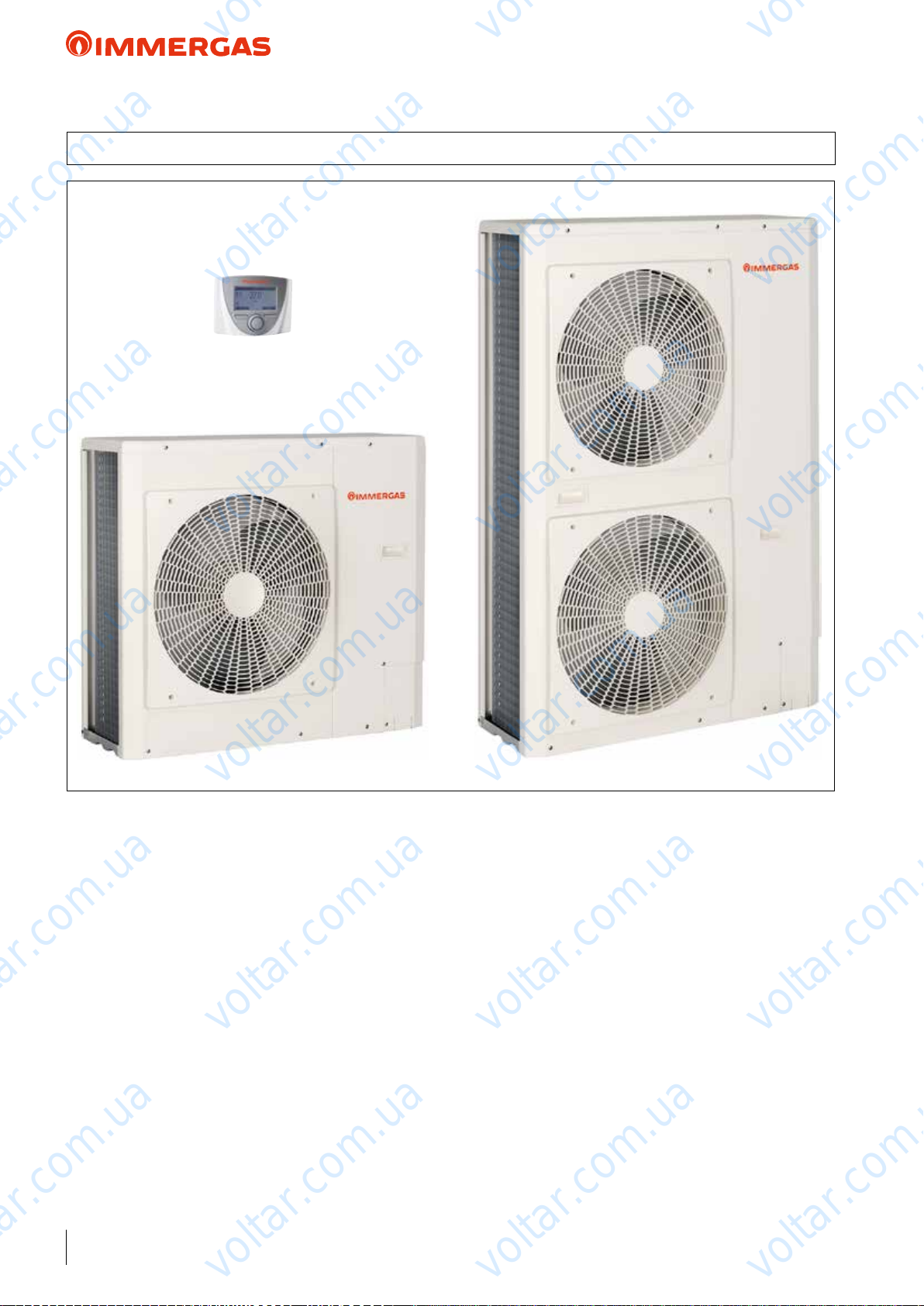
1 AUDAX TOP ErP DESCRIPTION
voltar.com.ua
voltar.com.ua
AUDAX TOP ErP
voltar.com.ua
voltar.com.ua
voltar.com.ua
voltar.com.ua
voltar.com.ua
voltar.com.ua
voltar.com.ua
A range of air/water reversible heat pumps with inverter technology. e mono-phase versions are available with AUDAX
TOP 6 ErP, AUDAX TOP 8 ErP and AUDAX TOP 12 ErP
models to full central heating and cooling requirements for
homes, oces, shops, etc...; while the three-phase versions are
available with AUDAX TOP 16 ErP, AUDAX TOP 18 ErP and
AUDAX TOP 21 ErP models to full central heating and cooling
requirements for large domestic systems (newly built large homes
such as duplexes, three-unit houses, condominiums), as well as
oces, shops, artisan activities, etc..
ese appliances are distinguished for their high energy eciency
and contained sound levels. ey can be used as a single generator to assist the system, but also inside an integrated system
(for example, with a heat pump - boiler - solar heating). ey
are engineering solutions that can be perfectly integrated with
each other, which allow to attain maximum benet from the
various energy production systems on the basis of the respective
eciency parameters.
For the entire system to operate correctly, Immergas oers an
“intelligent” system Manager capable of identifying the most
economical energy source at a given time and therefore choose
voltar.com.ua
voltar.com.ua
the right appliance to activate.
All AUDAX TOP ErP series models are equipped with a system
side plate heat exchanger and low energy consumption circulation pump, which facilitate installation. e maximum ow
temperature set-point with central heating is 60 °C (57 °C for
AUDAX TOP 21 ErP), which enables use of radiator systems
as well as fan coil or radiant systems.
e entire range complies with the requirements of ErP Directive
(2009/125/EC) and ELD (2010/30/EC). Various hydraulic,
electric and electronic kits are available, which enable exible
use in all circumstances.
voltar.com.ua
voltar.com.ua
voltar.com.ua
4
voltar.com.ua
voltar.com.ua
voltar.com.ua
Page 5
voltar.com.ua
voltar.com.ua
AUDAX TOP ErP
2 AUDAX TOP 6 8 12 ErP FEATURES MONOPHASE
voltar.com.ua
6 kW, 8 kW and 12 kW mono-phase inverter air/water heat
pumps for winter and summer air conditioning. e galvanised
steel structure makes the machines particularly suitable for
outdoor installation.
Main components:
• Control Panel - standard supply - which enables you to pro-
gram the machine and also functions as a room temperature/
humidity sensor. It also displays the error codes in the event
of malfunctions;
• R410A refrigerant gas (pre-loaded in the machine);
• Twin Rotary compressor with hybrid inverter activation in
direct current with PAM (Pulse Amplitude Modulation) and
PWM (Pulse Width Modulation) logic to oer improved
reliability, low energy consumption and vibration-free operation in all operating conditions and acoustic insulation with
sound-absorbing materials.
• cooling circuit including a compressor and air/gas refrigerant
nned coil, two-way electronic throttle valve, refrigerant gas/
water insulated stainless steel plate heat exchanger, 4-way
reversing valve (reversible heat pump cycle or cooling cycle
operation);
• variable speed fan with a 3-blade impeller characterised by an
innovative prole designed to guarantee better distribution of
air and contained sound levels (AUDAX TOP 6 - 8 ErP);
• double variable speed fan with a 3-blade impeller characterised
by an innovative prole designed to guarantee better distribution of air and contained sound levels (AUDAX TOP 12 ErP);
• system low energy consumption pump and ow switch to
ensure there is sucient water circulation to guarantee correct
operation of the hydronic and cooling circuits;
• 2 litre internal expansion vessel (AUDAX TOP 6 - 8 ErP);
• 3 litre internal expansion vessel (AUDAX TOP 12 ErP);
• 3 bar system safety valve;
• included and standard supply are the water Y lter 1”, vibra-
tion-dampening devices, condensate drain ttings and cable
clamp to pass electric cables;
• ow and return 1” M hydraulic connections situated at the
rear;
• electronic management system equipped with various sensors
situated in key positions of the cooling circuit to electronically
detect the system's operating status. e system's ow water
temperature is detected by means of a probe;
• option to pilot a 3-way diverter valve directly from AUDAX
TOP ErP for D.H.W. production heating and an external
booster pump on the system;
• maximum system water ow temperature up to 60 °C;
• operation up to outdoor air temperature of -20°C in winter
and +46°C in summer;
• protection against freezing up to -10°C as a result of periodic
activation of the pump and AUDAX TOP ErP cooling circuit
(with power supply voltage);
• IPX4 electrical insulation rating.
voltar.com.ua
voltar.com.ua
voltar.com.ua
voltar.com.ua
System solutions:
• Standalone system with AUDAX TOP ErP and integrative
resistance;
• can be coupled to a separate storage tank for DHW;
• can be coupled to a boiler via the System manager;
• can be coupled to a boiler and the solar heating system via the
voltar.com.ua
System manager.
• can be installed as a set conguration with the System manager.
Is available in the model:
• AUDAX TOP 6 ErP code 3.025557
• AUDAX TOP 8 ErP code 3.025558
• AUDAX TOP 12 ErP code 3.025560
EC Declaration Of Conformity.
voltar.com.ua
voltar.com.ua
voltar.com.ua
voltar.com.ua
voltar.com.ua
voltar.com.ua
voltar.com.ua
voltar.com.ua
voltar.com.ua
5
voltar.com.ua
Page 6
voltar.com.ua
voltar.com.ua
AUDAX TOP ErP
3 AUDAX TOP 16 18 21 ErP FEATURES THREEPHASE
voltar.com.ua
16 kW, 18 kW and 21 kW three-phase inverter air/water heat
pump for winter and summer air conditioning. e galvanised
steel structure makes the machines particularly suitable for
outdoor installation.
Main components:
• Control Panel - standard supply - which enables you to program the machine and also functions as a room temperature/
humidity sensor. It also displays the error codes in the event
of malfunctions;
• R410A refrigerant gas (pre-loaded in the machine);
• twin Rotary compressor with hybrid inverter activation in
direct current with PAM (Pulse Amplitude Modulation) and
PWM (Pulse Width Modulation) logic to oer improved
reliability, low energy consumption and vibration-free operation in all operating conditions and acoustic insulation with
sound-absorbing materials.
• cooling circuit including a compressor and air/gas refrigerant
nned coil, two-way electronic throttle valve (2 in the 21 kW
version), refrigerant gas/water insulated stainless steel plate
heat exchanger, 4-way reversing valve (reversible heat pump
cycle or cooling cycle operation);
• double fan variable speed with a 3-blade impeller characterised
by an innovative prole designed to guarantee better distribution of air and contained sound levels;
• modulating system low energy consumption pump and ow
switch to ensure there is sucient water circulation to guarantee correct operation of the hydronic and cooling circuits;
• 3 litre internal expansion vessel (16 kW);
• 8 litre internal expansion vessel (18 - 21 kW);
• 3 bar system safety valve;
• included and standard supply are the water Y lter 1”, vibration-dampening devices, condensate drain ttings and cable
clamp to pass electric cables;
• ow and return 1” M hydraulic connections situated at the
rear;
• electronic management system equipped with various sensors
situated in key positions of the cooling circuit to electronically
detect the system's operating status. e system's ow water
temperature is detected by means of a probe;
• option to pilot a 3-way diverter valve directly from AUDAX
TOP ErP for D.H.W. production heating and an external
booster pump on the system;
• maximum system water ow temperature up to 60 °C (57 °C
for AUDAX TOP 21 ErP);
• operation up to outdoor air temperature of -20°C in winter
and +46°C in summer;
• for AUDAX TOP 16 ErP protection against freezing up to -10°C
(with power supply voltage) as a result of periodic activation of the
pump and AUDAX TOP ErP cooling circuit;
• for AUDAX TOP 18-21 ErP protection against freezing up to -10°C
(with power supply voltage) as a result of periodic activation of the
pump and electric resistances;
• IPX4 electrical insulation rating.
voltar.com.ua
voltar.com.ua
voltar.com.ua
voltar.com.ua
System solutions:
• standalone system with AUDAX TOP ErP and integrative
resistance;
• can be coupled to a separate storage tank for DHW;
• can be coupled to a boiler via the System manager;
• can be coupled to a boiler and the solar heating system via the
voltar.com.ua
System manager.
• can be installed as a set conguration with the System manager.
Is available in the model:
• AUDAX TOP 16 ErP code 3.025562
• AUDAX TOP 18 ErP code 3.025563
• AUDAX TOP 21 ErP code 3.026940
EC Declaration Of Conformity.
voltar.com.ua
voltar.com.ua
voltar.com.ua
voltar.com.ua
voltar.com.ua
voltar.com.ua
voltar.com.ua
6
voltar.com.ua
voltar.com.ua
voltar.com.ua
Page 7
voltar.com.ua
voltar.com.ua
AUDAX TOP ErP and Integrated System
voltar.com.ua
voltar.com.ua
voltar.com.ua
voltar.com.ua
voltar.com.ua
voltar.com.ua
voltar.com.ua
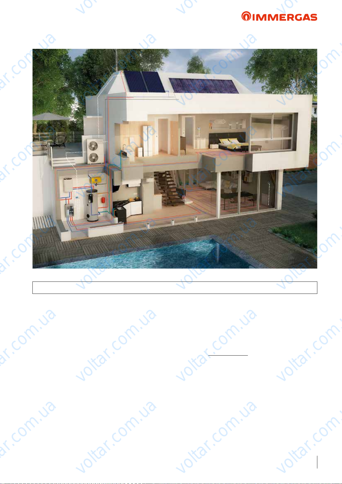
4 INTEGRATED SYSTEM FOR AIR CONDITIONING AND D.H.W. PRODUCTION
Comprised of a boiler – solar heating – heat pump and possibly
photovoltaic – etc, they are the natural evolution of air-conditioning systems: with very high seasonal eciency, low energy
consumption and reduced polluting emissions.
ey are engineering solutions that can be perfectly integrated
with each other, which allow to attain maximum benet from the
various energy production systems on the basis of the respective
eciency parameters.
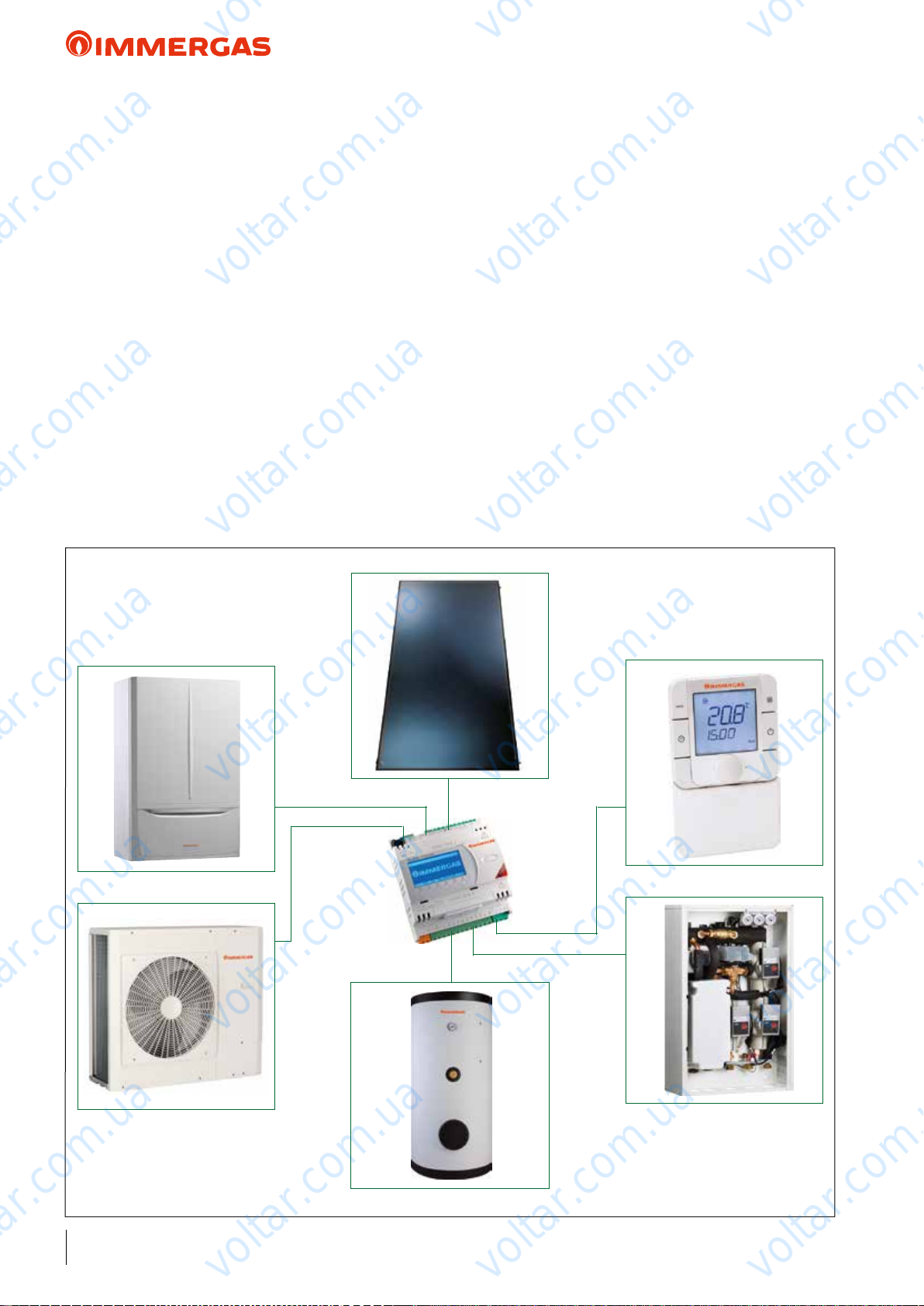
For the entire system to operate correctly, Immergas oers a
System Manager, able to:
- always make use of the most convenient heat source;
- keep the system performance high in every circumstance;
- control and command the entire system with a unique "brain"
(i.e. the System Manager);
- promote heat pump activation with a system that generates
electricity from renewable sources.
Basically, the System Manager is a supervisor that can control
the entire system).
Amongst other things, the following main operations are necessary:
voltar.com.ua
- acquire outdoor temperature (from the external probe, inserted
- set central heating side and cooling side (if provided) climatic
- congure the fuel cost (e.g. methane);
- congure the electric energy cost;
- set the AUDAX TOP ErP minimum integration (cut o) T.
e point of economic balance between the gas boiler and the
heat pump is a COP value between 2.4 and 2.6 approximately
(approximate value referred to methane); this value changes
based on the cost of electrical power and gas, in the location
voltar.com.ua
where the system is installed.
With sucient Toutdoor to full minCOP economical convenience, or Toutdoor is higher than Tminimum integration (cut o), the
heat pump starts and the performance eciency conditions are
constantly monitored. On the contrary, if the environmental
conditions are such that the AUDAX TOP ErP coecient of
performance tends towards lower values than COPmin for economical convenience, or outdoor T is less than minimum integration
(cut o) T, the system Manager starts the boiler (or integrative
resistance).
voltar.com.ua
as per standard on the heat pump);
curve operation to determine the system's ow temperature;
voltar.com.ua
voltar.com.ua
voltar.com.ua
voltar.com.ua
voltar.com.ua
7
voltar.com.ua
Page 8
voltar.com.ua
voltar.com.ua
AUDAX TOP ErP and Integrated System
voltar.com.ua
Each time AUDAX TOP ErP is operating, the Manager enables
an additional control, which checks the time it takes the system
to reach full operation: when a maximum time is exceeded (can
be set dierently between C.H. and D.H.W.) for the heat pump
to reach the owT, the boiler or integrative electrical resistance
is started.
It is also possible to choose the integration operation method
(boiler/resistance) between simultaneous or alternative Heat
Pump.
In all cases where radiant panels are also included for summer
cooling, alongside dehumidiers (see previous picture), the
System Manager will also monitor the dew point through the
installation of room probes (Immergas). anks to this intelligent
function the System Manager can increase the ow temperature
to the radiant panels by about 1°C (up to a maxT of 18°C - maximum limit of the cooling heat pump), avoiding the phenomenon
of condensation on the surface of the structure. is function can
only be activated with an Immergas accessory kit that controls
humidity. In some cases, for example, the System Manager can
turn the heat pump o if the ow temperature to the radiant
panels is not suciently corrected.
voltar.com.ua
voltar.com.ua
If on the other hand, there is a high temperature zone in the
system, in addition to the low temperature one, it will be served
exclusively by the boiler through an accordingly congured
dedicated expansion connected to the System Manager.
D.H.W: operation: amongst the possible congurations with
integrated systems is the option to connect the boiler and
AUDAX TOP ErP parallel with the same coil, and use a storage
tank probe with one DHW set for the entire storage tank, and set
voltar.com.ua
it in the system's Manager. If the system Manager is connected
to the boiler on external probe clamps (pre-set models), if the
set DHW temperature is < 50°C, the heat pump starts (always
checking the aforesaid convenience); however, if it is > 50°C,
AUDAX TOP ErP heats up to 50°C, then the boiler starts; if
there is no boiler but there is storage tank integrative electrical
resistance, the water is brought to 50°C via the heat pump and
AUDAX TOP ErP is then disabled, leaving the resistance to
integrate to the pre-set value.
In systems where there is a boiler or an integrative electrical
resistance on the storage tank, in addition to the heat pump, it
is also possible to enable the anti-legionella function.
voltar.com.ua
voltar.com.ua
voltar.com.ua
voltar.com.ua
voltar.com.ua
voltar.com.ua
voltar.com.ua
voltar.com.ua
voltar.com.ua
8
voltar.com.ua
voltar.com.ua
voltar.com.ua
Page 9
voltar.com.ua
voltar.com.ua
AUDAX TOP ErP
5 HEAT ADJUSTMENT WITH AUDAX TOP ErP CONTROL PANEL IN
STANDALONE APPLICATIONS (SETTING AND LOGIC OPERATION)
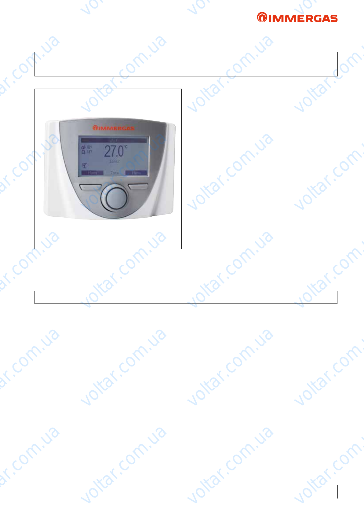
e Control Panel (standard supply with AUDAX TOP ErP)
enables programming of several operating options and relative
voltar.com.ua
voltar.com.ua
temperature/humidity control of the system.
voltar.com.ua
For example, the Control Panel acquires data regarding outdoor
temperature (from the external probe), system ow temperature
(regarding the pre-set climatic curve), and also the room's humidity percentage.
e standard Control Panel supplied is connected to a specic
terminal block on AUDAX TOP ErP, which enables you to
program the machine and also functions as a room temperature/
humidity sensor. It also displays the error codes in the event of
malfunctions.
e room sensor function can be disabled in order to use it only
to display the heat pump statuses and leave AUDAX TOP ErP
external control management on/o.
e user interface is composed of an LCD display, keys and an
encoder central knob.
voltar.com.ua
N.B.: With system Manager applications, the Control Panel
(standard) can also function as a room temperature/humidity
probe of a system's zone.
voltar.com.ua
voltar.com.ua
voltar.com.ua
Factory set device class: "VI"
Ref. European Commission Notice 2014/C 207/02
5.1 TECHNICAL FEATURES
e Control Panel (standard) with Standalone conguration,
enables:
• Operation with variable ow temperature according to outdoor
temperature (through the standard AUDAX TOP ErP external
probe supplied);
• Machine time band operation (C.H and cooling) in Comfort
or Economy mode;
• Any operation anomalies with error codes via system self-diagnosis displayed on the screen.
e Control Panel also manages the following data:
• External temperature (via external probe as per standard with
AUDAX TOP ErP);
• System ow temperature settings (C.H and cooling);
• Instant outlet temperature from the machine;
• Dew temperature;
• No. of machine operating hours.
Please note that AUDAX TOP ErP can:
• Directly pilot one/two 3-way diverter valves for D.H.W.
production, and can manage activation of an external booster
pump on the system;
• Manage activation of an auxiliary heat source (e.g. electrical
resistance);
voltar.com.ua
voltar.com.ua
voltar.com.ua
• Manage and an external alarm that forces machine shutdown;
• Limit the machine's frequency (to reduce noise).
NOTE: With Standalone applications to manage any dehumidiers, you can opt for On/O room thermostats + On/
O humidistats (connected parallel with AUDAX TOP ErP),
with a relay to split the humidistat request and also take it to
the dehumidiers.
TECHNICAL DATA
• Dimensions: 100 x 129 x 37 mm (H x L x D);
• Supply voltage: 15 Vdc (directly from the Heat Pump terminal
block);
• Maximum input: 2 VA;
voltar.com.ua
• 4-pole cable connection (type H03VV-F 5 x 0.75 mm2 ), max
length 50 m. Use wires having minimum sections of 0.5 mm2
and maximum 1.5 mm2;
• Casing protection rating: IP20.
voltar.com.ua
voltar.com.ua
voltar.com.ua
voltar.com.ua
9
voltar.com.ua
Page 10
voltar.com.ua
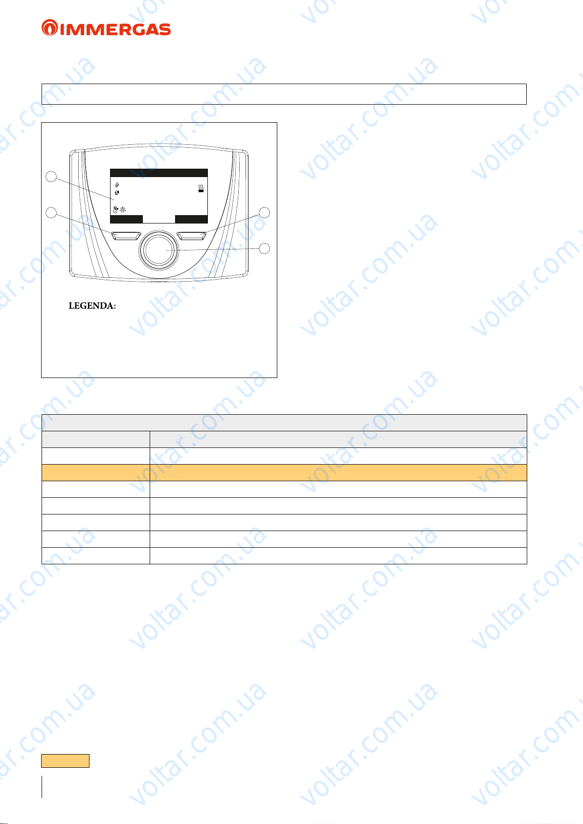
5.2 PROGRAMMING MENU
4
2
1 - Main parameters switch with button to
2 - Left context button
3 - Right context button
4 - Display
12:34 Fr 3 Jan 2014
voltar.com.ua
67%
20.6
13°C
Room set 21.0°C
Mode Menu
conrm and save data
voltar.com.ua
°C
3
1
voltar.com.ua
Once the device is powered, it goes into the status prior to switcho. Press the “Modo” (Mode) (2) button to cyclically select the
desired mode amongst those available.
Depending on the system's conguration, the main screen displays various information regarding the system.
voltar.com.ua
Press the “Menu” (3) button to access a list of variables that
enable you to customise use of the system.
To browse the menus, which can be accessed by pressing the
relative “RH” or “LH” context buttons, scroll through the
sub-menus displayed by turning the main switch (1).
Press the said main switch (1) to select the one highlighted.
erefore, by pressing repeatedly, you can scroll down the menu
levels and go back to a previous level by pressing the “Indietro”
(Back) context button. To exit the menu completely, press the
“Esci” (Exit) button, which will take you back to the initial page
of normal operation.
To conrm the parameter change, press the main switch (1).
voltar.com.ua
voltar.com.ua
AUDAX TOP ErP
voltar.com.ua
voltar.com.ua
MAIN MENU
Menu item Description
Set Point Zone Denes the operating parameters to manage the zone
Set Point DHW Denes the operation parameters in domestic circuit mode
Time and Program Denes the date/time and time operating ranges
Information Display system operating data
Historical alarm code Displays the list of the last 10 anomalies
Service Password protected menu dedicated to a qualied technician
Language Denes the control panel operation language
voltar.com.ua
voltar.com.ua
voltar.com.ua
voltar.com.ua
voltar.com.ua
voltar.com.ua
10
N.B. PARAMETERS ONLY VALID FOR AUDAX TOP 18 - 21 ErP
voltar.com.ua
voltar.com.ua
voltar.com.ua
Page 11
voltar.com.ua
voltar.com.ua
AUDAX TOP ErP
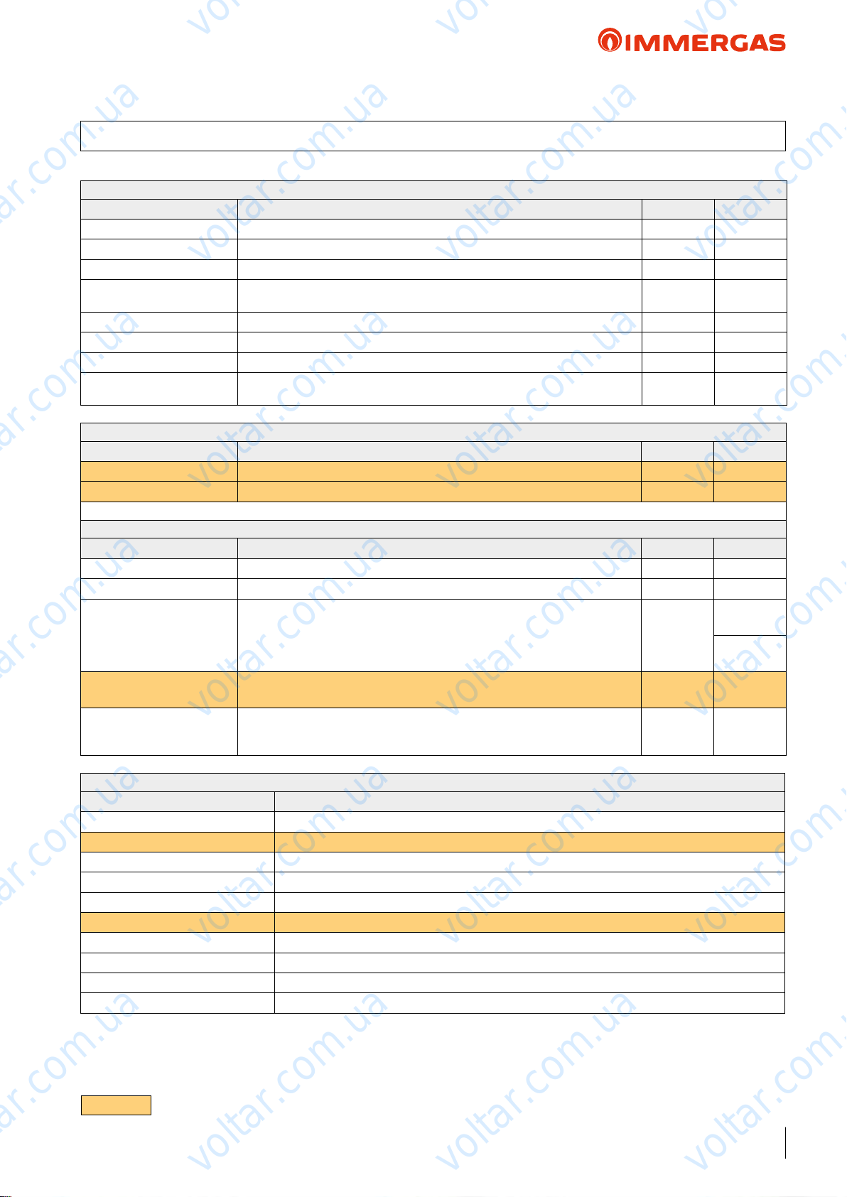
5.3 USER PROGRAMMING MENU
Menu Set Point Zone
Menu item Description Range Default
Set comfort heat. Room temperature in central heating zone Comfort mode 15 ÷ 35 °C 20
Set economy heat. Room temperature in central heating zone Economy mode 5 ÷ 25 °C 17
Set ow heat. Flow temperature in room zone central heating mode 20 ÷ 60°C 40
Oset ow heat. Oset temperature for central heating zone
Set comfort cool. Room temperature in cooling zone Comfort mode 15 ÷ 35 °C 25
Set economy cool. Room temperature in cooling zone Economy mode 15 ÷ 35 °C 28
Set ow cool. Flow temperature in room zone cooling mode 4 ÷ 25 °C 8
Oset ow cool. Oset temperature for cooling zone
Menu item Description Range Default
Set comfort DHW storage temperature in Comfort phase 30 ÷ 60 °C 50
Set economy DHW storage temperature in Economy phase 30 ÷ 45 °C 30
voltar.com.ua
Menu Set point DHW
voltar.com.ua
voltar.com.ua
- 15 ÷ + 15
°C
-15 ÷ + 15
°C
voltar.com.ua
voltar.com.ua
voltar.com.ua
0
0
voltar.com.ua
Menu Time and Programs
Menu item Description Range Default
Date and time Current date and time setting
Time slots Denes the time range for operation in Comfort and Economy mode
Program Zone Time programming for controlled zone
Program DHW DHW operation time programming
Denes the period during which the system disables both hot water heating and
voltar.com.ua
Program Holiday
Menu item Description
Flow temperature Instant outlet temperature from the system
Return temperature Instant inlet temperature to the system
External temperature External temperature detected by the external probe
Flow temp. system calc. Flow temperature requested by the generators
Dew point Dew temperature
Temp DHW Storage water temperature
Firmware board version Heat pump control board software revision
Firmware display version Display software revision installed on the control panel
H.P. hours of operation Number of operating hours of the heat pump
Mode of operation H.P. Describes the heat pump operation mode.
room central heating and/or cooling functions.
At the end of the set days, the previously active functions will be reset.
Menu Information
voltar.com.ua
voltar.com.ua
voltar.com.ua
Mon - Sun
voltar.com.ua
voltar.com.ua
Mon - Fri
Cal 1
Sat - Sun
Cal 3
Cal 1
Disabled
N.B. PARAMETERS ONLY VALID FOR AUDAX TOP 18 - 21 ErP
voltar.com.ua
voltar.com.ua
11
voltar.com.ua
Page 12
voltar.com.ua
voltar.com.ua
AUDAX TOP ErP
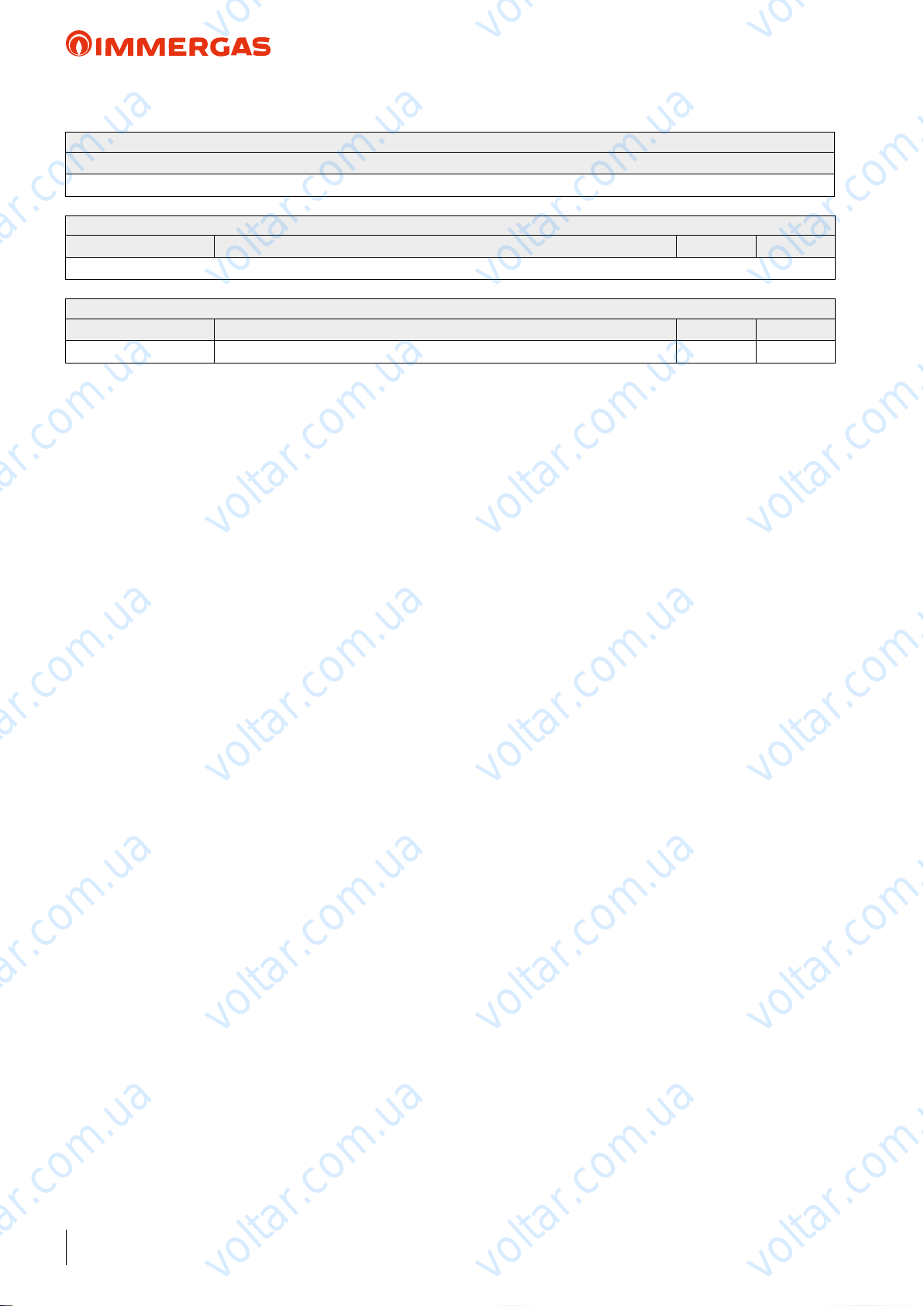
Menu Historical alarm code
Description
Displays the history log of the last 10 anomalies
Menu Service
Menu item Description Range Default
Password protected menu dedicated to a qualied technician
voltar.com.ua
Menu Language
Menu item Description Range Default
Language Denes the control panel operation language ITA - ENG ITA
voltar.com.ua
voltar.com.ua
voltar.com.ua
voltar.com.ua
voltar.com.ua
voltar.com.ua
voltar.com.ua
voltar.com.ua
voltar.com.ua
12
voltar.com.ua
voltar.com.ua
voltar.com.ua
voltar.com.ua
voltar.com.ua
voltar.com.ua
Page 13
voltar.com.ua
voltar.com.ua
AUDAX TOP ErP
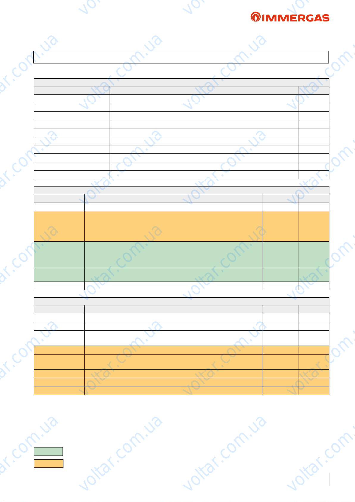
5.4 MAINTENANCE TECHNICIAN PROGRAMMING MENU
Menu Service
Menu item Description Range
Denition of zone Zone system sub-menu settings -
Dening plant Sub-menu to dene the devices connected to the system -
Device conguration Sub-menu to set the device's conguration -
ermoreg. heat. Central heating thermoregulation setting sub-menu -
ermoreg. cool Cooling thermoregulation setting sub-menu -
ermoreg. parameters Parameters thermoregulation setting sub-menu -
Integration System integration setting sub-menu -
Heat pump Heat pump operating parameters sub-menu -
Manual Manual operating parameters sub-menu -
Factory settings Default settings restore sub-menu Yes / No
voltar.com.ua
voltar.com.ua
voltar.com.ua
voltar.com.ua
Menu Service -> Denition of Zone
Menu item Description Range Default
Mode Display the operating mode
Room control inter-
face
Enable Remote
Control
Enable thermostat
Enable dew point Enable operation with a humidity probe in the control panel. Yes / No No
Menu item Description Range Default
External probe Enables operation with the external probe.
Enable DHW Operation in domestic circuit
Reduction function
Power Power percentage in reduction mode. 50% ÷ 100% 75%
Circulator control
Speed Min Value of minimum speed used in modulating operation. 19% ÷ 50% 50%
Speed Max Value of maximum speed used in modulating operation. 50% ÷ 100% 100%
Delta T Temperature delta to be maintained with modulating operation. 2 ÷ 20 5
voltar.com.ua
Enable operation of the supplied control panel if set on “R. Panel”.
If “TA” set, the central heating and cooling requests will be made based on the
request of an external thermostat.
Enable operation of the supplied control panel.
If “No” is set, the control panel only displays the heat pump statuses.
N.B.: setting “No”, it is compulsory to enable the room thermostat (refer to the
next item), otherwise the machine will display an anomaly.
Enable operation of a room thermostat to check the heat pump
PdC is controlled by contacts in the said P.C.B.
voltar.com.ua
Enable PdC operation frequency reduction, which is controlled by the said terminal
board.
Enable the pump operation with speed set “Max.speeed” or the modulating mode
with tracking of the “Modulating” temperature dierential.
Menu Service -> Dening Plant
voltar.com.ua
voltar.com.ua
- Heat + Cool
Remote Pan-
el/T.A.
Yes / No Ye s
Yes / No No
voltar.com.ua
No / PdC
Yes / No
Yes / No No
Max.speed/
Modulating
voltar.com.ua
voltar.com.ua
R.Panel
voltar.com.ua
Modulating
voltar.com.ua
-
No
No
N.B. PARAMETERS ONLY VALID FOR AUDAX TOP 6 - 8 - 12 - 16 ErP
N.B. PARAMETERS ONLY VALID FOR AUDAX TOP 18 - 21 ErP
voltar.com.ua
voltar.com.ua
13
voltar.com.ua
Page 14

voltar.com.ua
voltar.com.ua
AUDAX TOP ErP
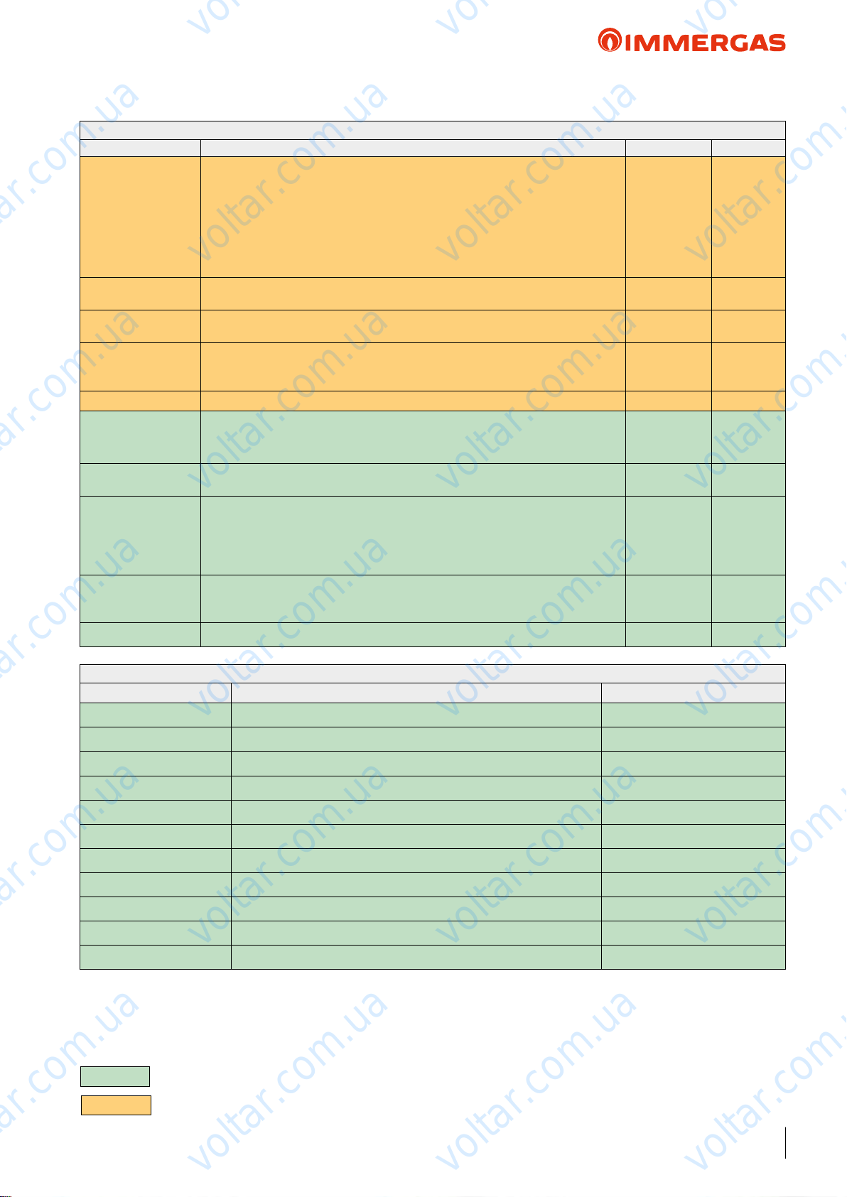
Menu Service -> Device conguration
Menu item Description Range Default
Setting “Yes”, the default control panel supplied manages the heat pump.
Setting “No”, the control panel does not control the heat pump and must be cou-
H.P. control
Slave address
Menu item Description Range Default
Discharge Set min
Discharge Set max
External Temp. min
External Temp. max
pled with other Immergas systems (for example, TRIO, MAGIS HERCULES, Or
System manager). If “No” is set, it displays another item “slave address”.
N.B.: if it is erroneously set to “No”, it is still possible to change the selection.
Address to congure according to the zone where the device is installed (e.g.: zone 1
= 41, zone 2 = 42, zone 3 = 43, etc...).
voltar.com.ua
Menu Service -> ermoreg. Heat
Without the external probe it denes the minimum ow temperature that can be
set by the user. With the external probe present it denes the minimum ow temperature corresponding to operation with maximum external temperature
Without the external probe it denes the maximum ow temperature that can be
set by the user. With the external probe present it denes the maximum ow temperature corresponding to operation with minimum external temperature
With the external probe present it denes at what minimum external temperature
the system must operate at the maximum ow temperature
With the external probe present it denes at what maximum external temperature
the system must operate at the minimum ow temperature
voltar.com.ua
voltar.com.ua
voltar.com.ua
Yes / No Ye s
1 ÷ 247 -
20 ÷ 45 °C 30°C
35 ÷ 60 °C 50 °C
-25 ÷ +15 °C -5 °C
-5 ÷ +45 °C 20°C
voltar.com.ua
voltar.com.ua
voltar.com.ua
Menu Service -> ermoreg. Cool
Menu item Description Range Default
Without the external probe it denes the minimum ow that can be set by the user.
Discharge Set min
Discharge Set max
External Temp. min
External Temp. max
Menu item Description Range
Room probe modul.
System inertia
Antifreeze enable Enables the room antifreeze function Yes / No Yes
Antifreeze set Allows to set the room temperature for activation of the anti-freeze function 0 ÷ 10 °C 5 °C
With the external probe present it denes the minimum ow temperature corresponding to operation with maximum external temperature
Without the external probe it denes the maximum ow that can be set by the user.
With the external probe present it denes the maximum ow temperature corresponding to operation with minimum external temperature
With the external probe present, it denes at what maximum external temperature
the system must operate at the minimum ow temperature
With the external probe present, it denes at what minimum external temperature
the system must operate at the maximum ow temperature
voltar.com.ua
Menu Service -> ermoreg. Parameters
It enables you to set operation of the control panel as modulating on/o: Set “Yes”, the
ow temperature will be varied depending on the room temperature set. Set “No”, the
ow temperature will be kept constant until the desired room temperature is reached.
N.B.: if an outdoor temperature probe is present, the ow temperature will be set
depending on the relative functioning curve
It establishes the system reaction speed according to the type of system present.
Example:
5 system with little heat inertia
10 system with normal dimensions with radiators
20 system with a lot of heat inertia (e.g. oor-standing system)
voltar.com.ua
voltar.com.ua
voltar.com.ua
4 ÷ 20 °C 7 °C
10 ÷ 25 °C 12 °C
20 ÷ 45 °C 20°C
20 ÷ 45 °C 35 °C
voltar.com.ua
Yes / No Yes
1 ÷ 20 10
voltar.com.ua
14
voltar.com.ua
voltar.com.ua
voltar.com.ua
Page 15
voltar.com.ua
voltar.com.ua
voltar.com.ua
AUDAX TOP ErP
Menu Service -> Integration
Menu item Description Range Default
- None
- Sys.
Electrical integration
Contemp. Temp.
intgr.
Min. temp. of inte-
gration
Waiting time integra-
tion
Counter reset H.P. Reset the number of operating hours of the heat pump Yes / No No
Integration device It establishes the type of integration in the system
Min. Temp. of inte-
gration
Contemp. Temp.
integration
Waiting time integra-
tion
Counter Reset H.P. Reset the number of operating hours of the heat pump Yes / No No
It establishes the type of integration in the system: “Sys.” enables the system integration, “San” the DHW integration, “San+Sys.” enables both integrations
voltar.com.ua
Temperature threshold below which integration is activated and the heat pump
maintained on.
Temperature threshold below which integration is activated and the heat pump is
switched o.
Standby to reach the set value before activating integration when outdoor temperature is below the previously set temperature values (minimum integration temperature and simultaneous integration temperature).
Temperature threshold below which integration is activated and the heat pump is
switched o
voltar.com.ua
A value that is equal to, or higher than, the minimum integration temperature must
be set.
Activate central heating integration when the outdoor temperature is below the set
value, the set intake requested has not been reached, and the heat pump remains
active
Standby to reach the set value before activating integration when outdoor temperature is below the previously set temperature values (minimum integration temperature and simultaneous integration temperature)
voltar.com.ua
voltar.com.ua
- N.A.
- N.A.
- N.A.
- San
- San + Sys.
-20 ÷ +15 °C -20 °C
-20 ÷ +15 °C -20 °C
5 ÷ 120’ 60’
- None
- Electrical resistance
-20 ÷ +30 °C -20 °C
0 ÷ 60 °C 20°C
0 ÷ 600’ 60’
voltar.com.ua
voltar.com.ua
None
None
Menu Service -> Heat pump
Menu item Description Range
Flow temperature Instant outlet temperature from the system
Flow temp. system calc. Flow temperature requested by the generators
Comp. discharge temp. Current heat pump compressor temperature 0 ÷ 100 °C
Comp. suction temp. Compressor inlet temperature -20 ÷ 100 °C
BPHE refrigerant temp. Coolant temperature inside the plate heat exchanger -20 ÷ 100 °C
Coil refrigerant temp. Battery temperature -20 ÷ 100 °C
Outdoor Air Temp. Room temperature -20 ÷ 100 °C
Max freq. compressor Maximum frequency in current operating conditions 0 ÷ 200 Hz
Requested frequency Frequency requested by the control board 0 ÷ 200 Hz
Actual frequency Current compressor frequency 0 ÷ 200 Hz
Compressor runtime Number of hours of operation of the compressor
N.B. PARAMETERS ONLY VALID FOR AUDAX TOP 6 - 8 - 12 - 16 ErP
voltar.com.ua
voltar.com.ua
voltar.com.ua
voltar.com.ua
voltar.com.ua
voltar.com.ua
N.B. PARAMETERS ONLY VALID FOR AUDAX TOP 18 - 21 ErP
voltar.com.ua
voltar.com.ua
15
voltar.com.ua
Page 16
voltar.com.ua
voltar.com.ua
AUDAX TOP ErP
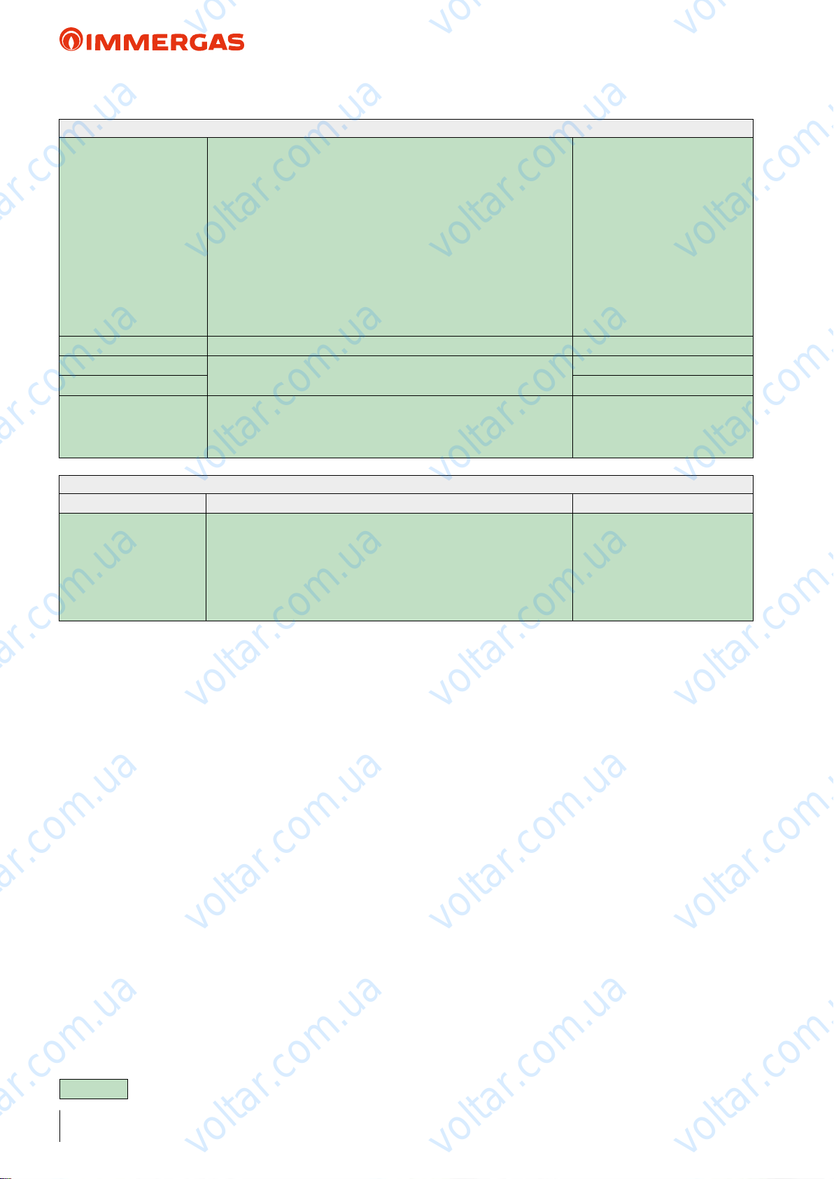
Menu Service -> Heat pump
0 = O
1 = Standby
2 = Cooling
3 = Central heating
4 = Extra central heating
5 = Extra cooling
System mode Indicates the system's operating mode
voltar.com.ua
Flow switch Indicates circulation inside the hydraulic circulator On / O
Flag anomalies H
Flag anomalies L
Communication status
Indicates any multiple anomalies on the heat pump
Indicates the communication status between the control panel and heat
pump
2 or more than 2 = communication OK
0 = communication problem
voltar.com.ua
6 = Central heating reduction
7 = Cooling reduction
8 = Antifreeze protection
9 = Defrosting
10 = High temperature protection
11 = Surveillance time
12 = Anomaly
voltar.com.ua
voltar.com.ua
voltar.com.ua
Menu item Description Range
0 = No manual forcing
1 = “On” heat pump circulator
2 = “On” alarm outlet on clamp N° 5
Manual
N.B: Before exiting this menu, remember to bring the value to “0” (zero) for correct operation.
3 = “On” external circulator on clamp N° 4
4 = Alarm/defrosting outlet on clamp N° 11
5 = Outlet for integration resistance on clamp N° 12
6 = DHW 3-way valve outlet on clamp N°10
Menu Service -> Manual
voltar.com.ua
voltar.com.ua
voltar.com.ua
voltar.com.ua
0 ÷ 6
voltar.com.ua
16
voltar.com.ua
N.B. PARAMETERS ONLY VALID FOR AUDAX TOP 6 - 8 - 12 - 16 ErP
voltar.com.ua
voltar.com.ua
voltar.com.ua
voltar.com.ua
voltar.com.ua
Page 17

voltar.com.ua
voltar.com.ua
AUDAX TOP ErP
Menu Heat Pump
Menu item Description Range
Working parameters Sub-menu for working data -
State Sub-menu for operating state -
Auxiliary info Sub-menu with other operating data -
P.C.B. settings Sub-menu to congure the P.C.B.
voltar.com.ua
voltar.com.ua
Menu item Description Range
Flow temperature Instant outlet temperature from the system
Return temperature Instant inlet temperature to the system
Calculated system temperature
set
Compressor outlet temperature Current heat pump compressor temperature
Compressor intake temperature Compressor inlet temperature
Compressor intake sat. temper-
ature
Coolant temperature on ex-
changer
Coil temperature low part Coil temperature, low side
Coil temperature high part Coil temperature, high side
External Temperature External room temperature
PdC frequency Current compressor frequency
System mode Indicates the system's operating mode
voltar.com.ua
Flow temperature requested by the generator
Compressor inlet saturation temperature
Coolant temperature inside the plate heat exchanger
Menu Heat Pump -> Working parameters
voltar.com.ua
voltar.com.ua
voltar.com.ua
voltar.com.ua
voltar.com.ua
voltar.com.ua
0=O
1 = Cooling
2 = Central heating
4 = DHW
6 = Central heating integration
7 = Defrosting
24 = DHW met
100 = Anomaly
101 = Cooling anomaly
102 = Central heating anomaly
104 = DHW anomaly
106 = Integration anomaly
107 = Defrosting anomaly
voltar.com.ua
voltar.com.ua
N.B. PARAMETERS ONLY VALID FOR AUDAX TOP 18 - 21 ErP
voltar.com.ua
voltar.com.ua
voltar.com.ua
voltar.com.ua
17
voltar.com.ua
Page 18

voltar.com.ua
voltar.com.ua
AUDAX TOP ErP
Menu Heat Pump -> State
Menu item Description Range
0 = O
1 = Wait after ignition
2 = Minimum compressor on time
3 = Minimum compressor o time
voltar.com.ua
voltar.com.ua
System stat Indicates the current system mode
voltar.com.ua
4 = delay for mode change
voltar.com.ua
5 = Step 1 compressor
6 = Step 2 compressor
7 = Step 3 compressor
8 = Step 4 compressor
9 = Compressor stop delay
11 - Frequency reduction on
20 = Defrosting
39 = Minimum external temperature for central
heating
40 = Maximum external temperature for central
heating
41 = Maximum ow/return value in central heating
42 = Low external temperature in central heating
43 = Very high external temperature in central heating
44 = High external temperature (compressor limita-
voltar.com.ua
tion)
45 = Step 1 High temperature protection in central
heating
46 = Step 2 High temperature protection in central
heating
47 = Step 3 High temperature protection in central
heating
48 = Step 4 High temperature protection in central
heating
50 = Minimum external temperature for cooling phase
51 = Minimum machine inlet temperature for cooling
phase
52 = External temperature <15°C in cooling phase
53 = External temperature >26°C in cooling phase
54 = External temperature >40°C in cooling phase
voltar.com.ua
55 = Low saturation temperature
57 = Step 2 antifreeze protection in cooling
58 = Step 1 antifreeze protection in cooling
61 = External temperature <0°C and ow temperature
> 12°C in cooling phase
62 = External temperature <0°C in cooling phase
70 = Protection for lack of ow rate
80 = Protection for oil return
85 = Compressor o from inverter
91 = Central heating integration
voltar.com.ua
voltar.com.ua
voltar.com.ua
voltar.com.ua
18
voltar.com.ua
N.B. PARAMETERS ONLY VALID FOR AUDAX TOP 18 - 21 ErP
voltar.com.ua
voltar.com.ua
voltar.com.ua
voltar.com.ua
voltar.com.ua
Page 19
voltar.com.ua
voltar.com.ua
AUDAX TOP ErP
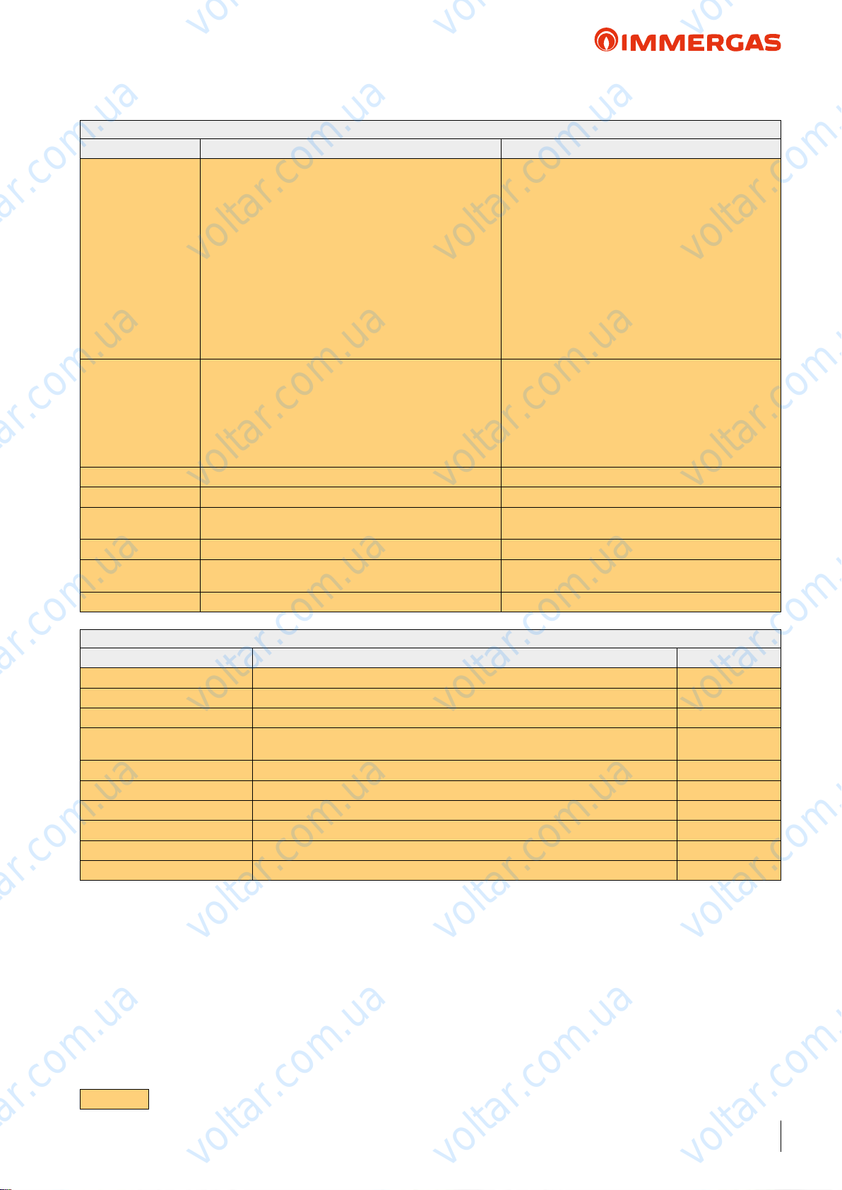
Menu Heat Pump -> State
Menu item Description Range
-1 = integration disabled
0 = O
1 = Integration on
2 = Integration on
3 = Integration on during defrosting
Integration status Indicates the operating mode of the part of integration
DHW state Indicates the operating mode during DHW request
voltar.com.ua
voltar.com.ua
4 = Integration on for heat pump anomaly
5 = Integration on for low external temperature
12 = Integration o for DHW request
13 = Capacity Limit
50 = Integration not allowed
51 = No CH request
100 = Integration anomaly
-1 = DHW disabled
0 = DHW enabled
1 = DHW not active (request for central heating or
cooling)
2 = ree-way DHW drive
100 = DHW anomaly
voltar.com.ua
voltar.com.ua
Flow switch Indicates circulation inside the hydraulic circulator On/o
Input status On/o Indicates the input state for the on/o control On/O
DHW Request
Input status reduction Indicates the input state for the reduction control On/O
Fault
(Current alarm code)
Fault Inverter Inverter anomaly code
Menu item Description Range
Overheating temp. Indicates the overheated gas temperature
Overheating target temp. Indicates the overheated gas required temperature
Inverter Temp. Indicates the inverter temperature
Max freq. compressor
Requested frequency Indicates the frequency requested from the compressor
Fan speed Top Indicates the upper fan speed
Fan speed Low Indicates the lower fan speed
Circulator speed Indicates the pump speed
Water control point Temperature control set
Water temp. control Reference probe for the temperature control set
voltar.com.ua
Indicates the presence of a heat request by the DHW
storage
Current anomaly code
Menu Heat Pump -> Auxiliary info
voltar.com.ua
Indicates the maximum frequency that can be reached by the compressor with the
present conditions
voltar.com.ua
voltar.com.ua
On/O
voltar.com.ua
voltar.com.ua
voltar.com.ua
N.B. PARAMETERS ONLY VALID FOR AUDAX TOP 18 - 21 ErP
voltar.com.ua
voltar.com.ua
voltar.com.ua
voltar.com.ua
19
voltar.com.ua
Page 20
voltar.com.ua
voltar.com.ua
AUDAX TOP ErP
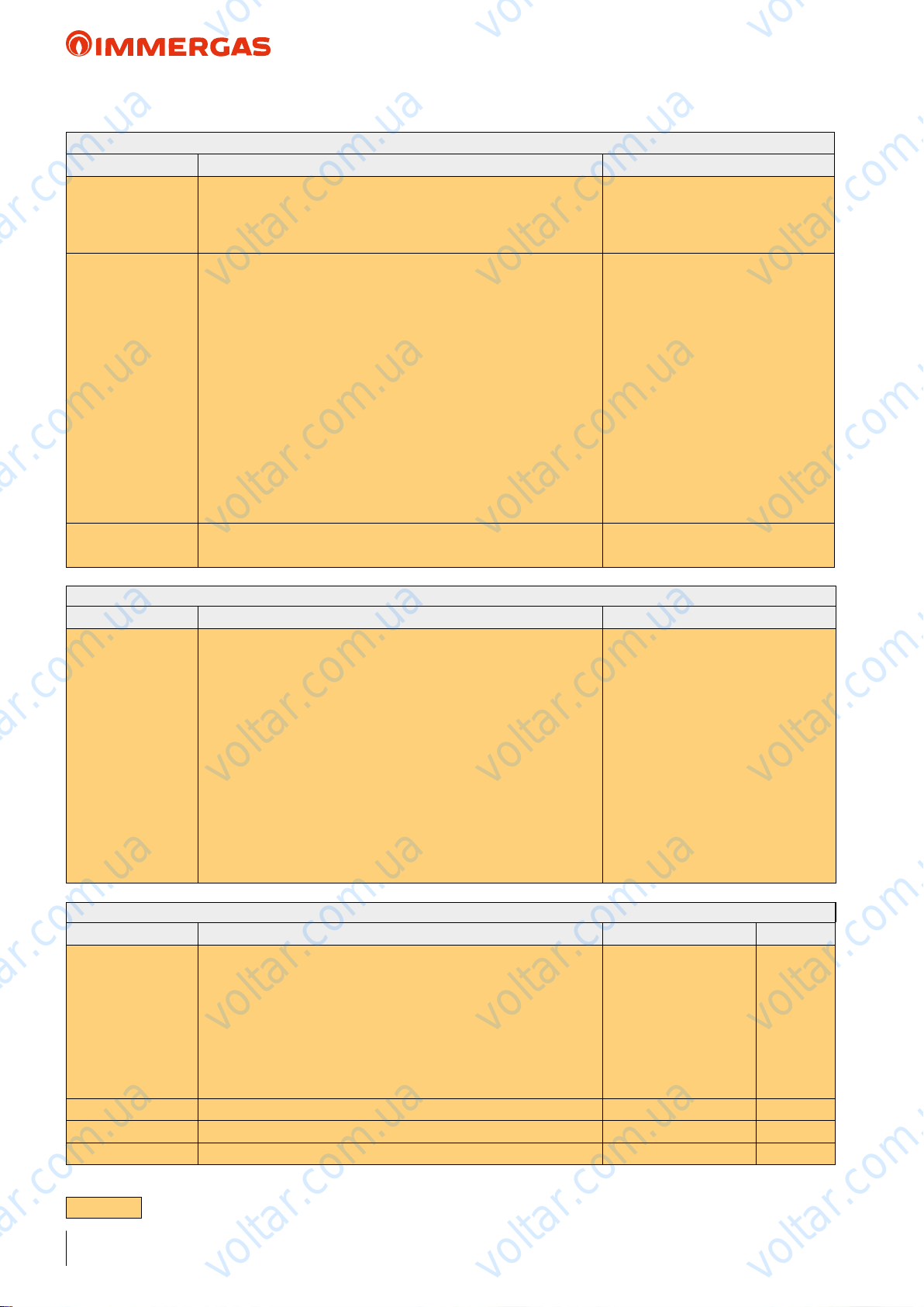
Menu Heat Pump -> P.C.B. settings
Menu item Description Range
- Central heating
Unit Type It establishes whether the machine is of reversible type
voltar.com.ua
Unit Size It establishes the Unit power
Power Supply
integration
voltar.com.ua
It denes the Unit power supply voltage 230Vac - 400Vac
voltar.com.ua
voltar.com.ua
- Cooling
- Central heating + Cooling
- 6 KW
- N.A.
- 8 KW
- N.A.
- N.A.
- N.A.
- 12 KW
- N.A.
- N.A.
- N.A.
- 16 KW
- N.A.
- 18 KW
- N.A.
- N.A.
- 21 KW
voltar.com.ua
voltar.com.ua
voltar.com.ua
Menu Service -> Test switch Max. press.
Menu item Description Range
0 = O
1 = Test required
N.B. the following states are managed by
the machine DO NOT USE
Test method for high pressure switch.
Test pressure switch
N.B. to run the test, set the value to 1 and wait for the test result
voltar.com.ua
Menu Service -> Manual
Menu item Description Range Default
Forcing of the heat pump operation
Manual operation
N.B. all controls on the ow and return sensors are disabled with these
voltar.com.ua
modes.
voltar.com.ua
voltar.com.ua
2 = AP Test in progress
3 = AP Test performed correctly
4 = AP Test failed for maximum time
reached
5 = AP Test failed for ow switch error
6 = AP Test failed for low water temperature
7 = AP Test failed for inverter error
0 = O
1 = Test cooling
2 = Test central heating
3 = Test cooling with
ramp
4 = Test central heating
with ramp
voltar.com.ua
0
voltar.com.ua
Circulator speed Pump speed forcing 0% ÷100% 0%
Flow switch Indicates circulation inside the hydraulic circulator O/On
ree way DHW Force the output for the DHW 3-way control O/On O
N.B. PARAMETERS ONLY VALID FOR AUDAX TOP 18 - 21 ErP
20
voltar.com.ua
voltar.com.ua
voltar.com.ua
Page 21
voltar.com.ua
voltar.com.ua
AUDAX TOP ErP
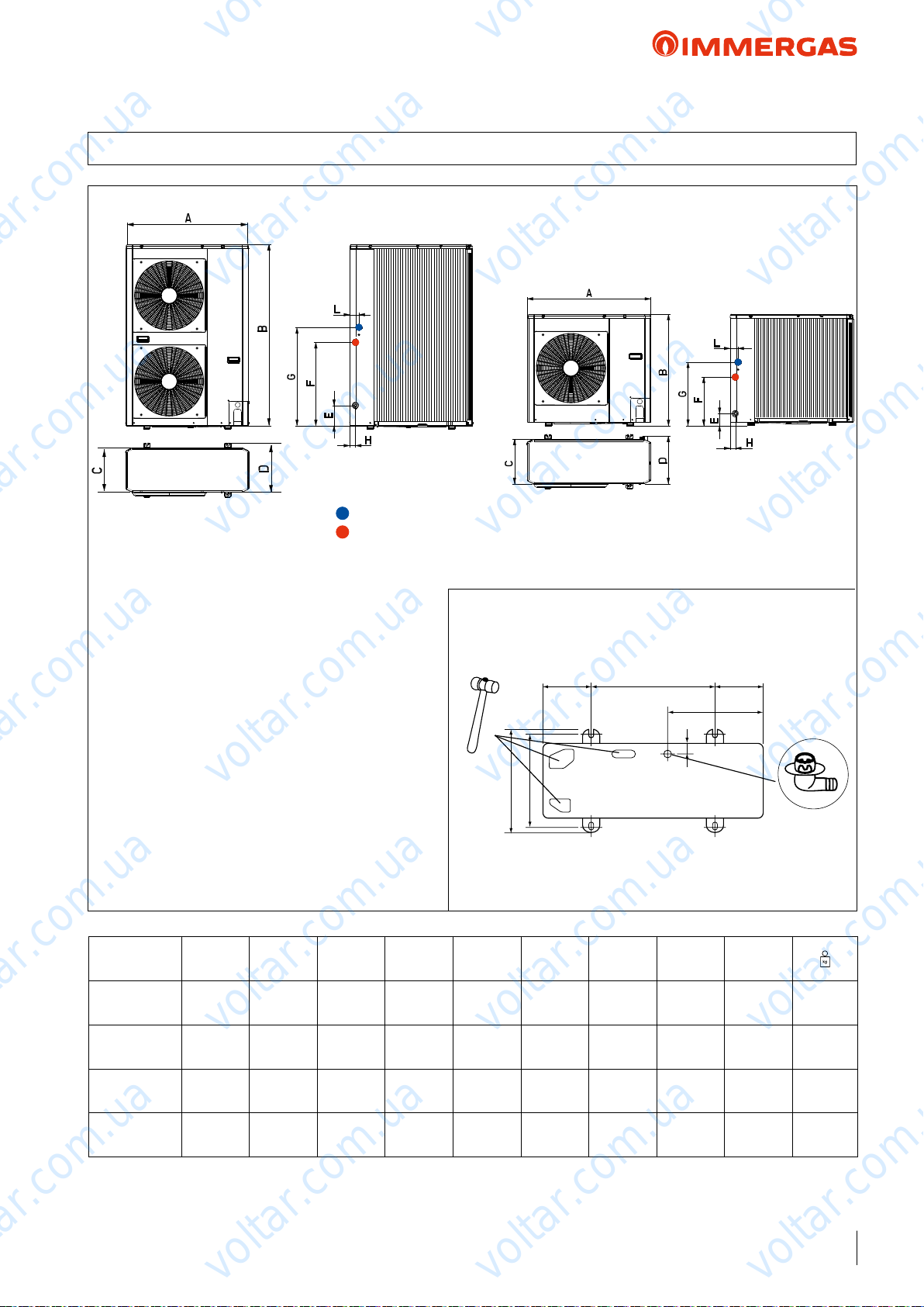
6 AUDAX TOP 6 8 12 16 ErP DIMENSIONS AND CONNECTIONS
voltar.com.ua
voltar.com.ua
System return = 1"M
voltar.com.ua
Condensate drain pipe and pre-cut holes in the
base. If draining is carried out through the drain pipe,
connect the drain tting (A) supplied, and use the
drain pipe (internal diameter: 16 mm) available on the
market. In the event of installation in very cold zones
or zones subject to heavy snow where the condensate
drain pipe can freeze, check the draining capacity of
the pipe. Draining capacity increases when the pre-cut
holes at the base, which collect condensate, are open
(open the pre-cut holes outwards with the aid of a
hammer with smooth edges).
N.B.: e gure on the side shows the measurements
to use to secure the machine (600 x 363). You must
insert the vibration-dampening devices supplied with
the product between AUDAX TOP ErP and the
support base.
voltar.com.ua
System ow = 1"M
voltar.com.ua
voltar.com.ua
600 051051
37
B
voltar.com.ua
363
400
voltar.com.ua
voltar.com.ua
430
voltar.com.ua
A
AUDAX TOP
ErP
6 kW
single phase
8 kW
single phase
12 kW
single phase
16 kW
three phase
A B C D E F G H L
908 821 326 350 87 356 466 40 60 61
voltar.com.ua
908 821 326 350 87 356 466 40 60 69
908 1363 326 350 174 640 750 44 69 104
908 1363 326 350 174 640 750 44 69 116
voltar.com.ua
voltar.com.ua
voltar.com.ua
voltar.com.ua
voltar.com.ua
21
Page 22
voltar.com.ua
voltar.com.ua
AUDAX TOP ErP
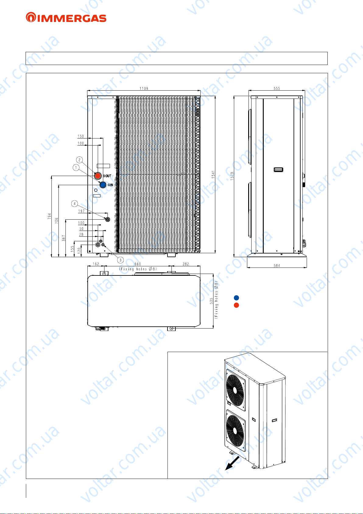
6.1 AUDAX TOP 18 21 ErP DIMENSIONS AND CONNECTIONS
voltar.com.ua
voltar.com.ua
voltar.com.ua
voltar.com.ua
voltar.com.ua
voltar.com.ua
voltar.com.ua
voltar.com.ua
Slots for condensate drain. Any condensate is drained
through the slots created under the nned barrier. In
the event of installation in very cold zones or zones
subject to heavy snow where the condensate can freeze,
take the necessary precautions to prevent any frozen
zones from causing falls or accidents.
N.B.: e following gure shows the measurements
to use to secure the machine (660 x 535). You must
insert the vibration-dampening devices supplied with
the product between AUDAX TOP 18 - 21 ErP and
the support base. Immergas proposes a kit made up of
4 vibration-dampening feet (optional) code 3.027654.
voltar.com.ua
System return = 1"1/4 M *
voltar.com.ua
System ow = 1"M
*1” M Reduction standard supplied
voltar.com.ua
voltar.com.ua
voltar.com.ua
22
voltar.com.ua
voltar.com.ua
voltar.com.ua
Page 23
voltar.com.ua
voltar.com.ua
AUDAX TOP ErP
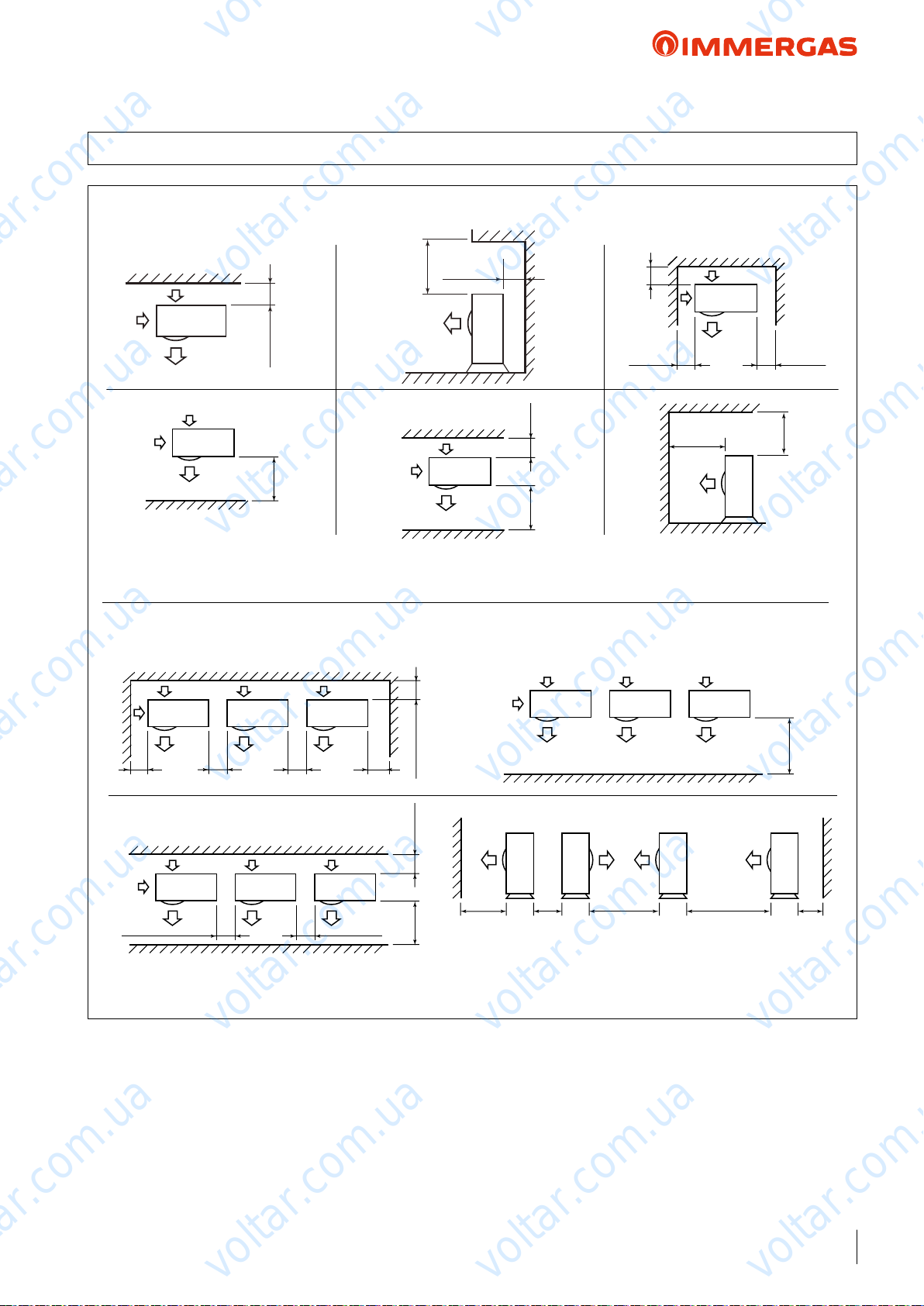
7 AUDAX TOP 6 8 12 16 ErP MINIMUM INSTALLATION DISTANCES
150
voltar.com.ua
500
voltar.com.ua
200
voltar.com.ua
voltar.com.ua
150
500
voltar.com.ua
150150
300300
300
voltar.com.ua
200
150
1000
1000
voltar.com.ua
voltar.com.ua
003051
1000
voltar.com.ua
1000
voltar.com.ua
200
300
300
1000
voltar.com.ua
voltar.com.ua
300
000200510001
voltar.com.ua
voltar.com.ua
200
voltar.com.ua
23
voltar.com.ua
Page 24
voltar.com.ua
voltar.com.ua
AUDAX TOP ErP
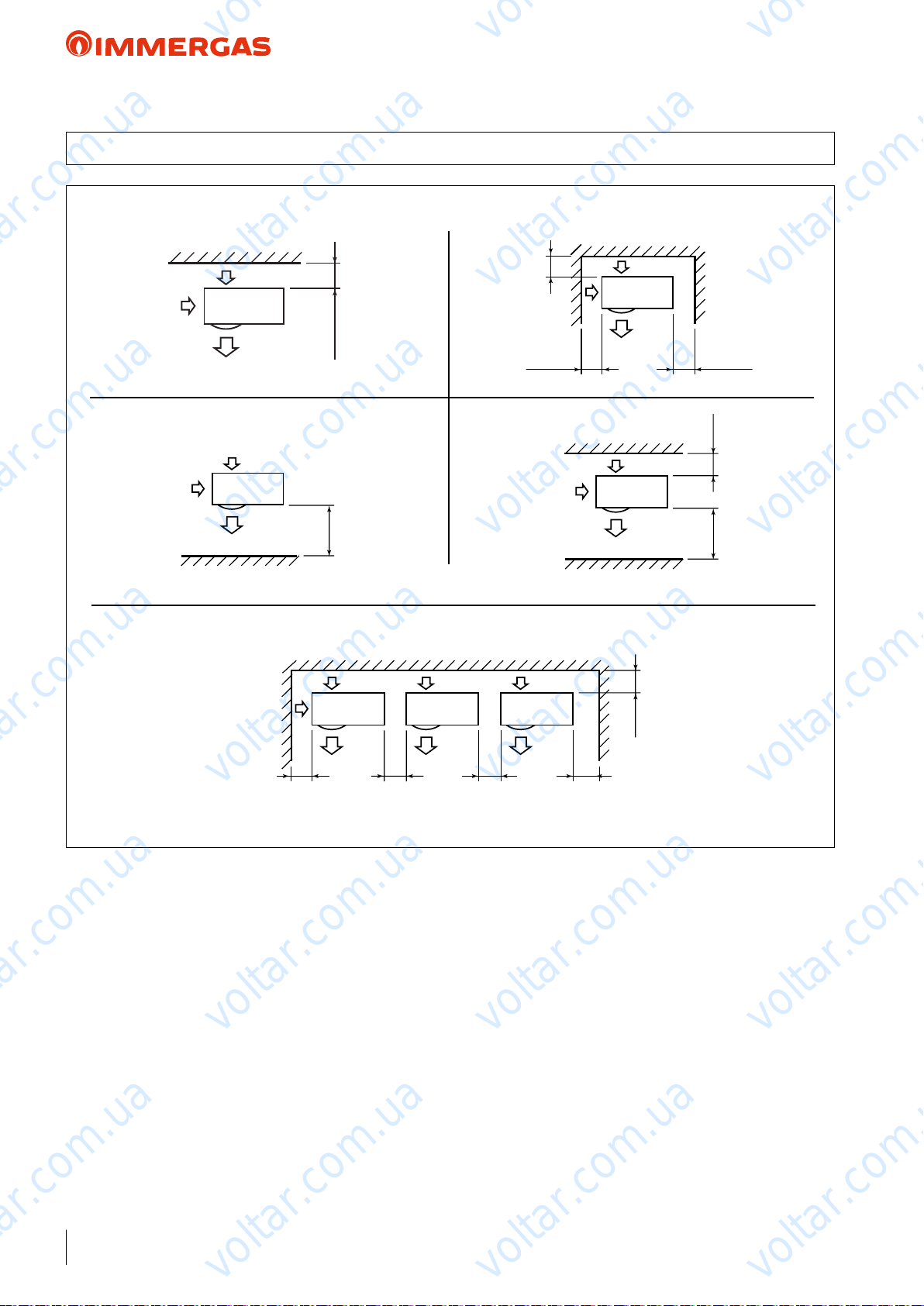
7.1 AUDAX TOP 18 21 ErP MINIMUM INSTALLATION DISTANCES
voltar.com.ua
voltar.com.ua
200
voltar.com.ua
1000
voltar.com.ua
300
5000200
200
voltar.com.ua
1000
voltar.com.ua
voltar.com.ua
voltar.com.ua
Place of installation:
e place of installation is very important and must be established by the system's designer or by a specically qualied
person, and must consider the technical requirements, standards
and laws in force.
• e unit must be installed outdoors only;
• It is recommended to avoid:
- positioning in basement windows
- obstacles or barriers that cause recirculation of exhaust air;
- places with aggressive atmospheres;
- limited spaces or anyhow in places where sound levels from
the appliance can be enhanced through reverberations or
resonance;
- positioning in corners where there is an accumulation of dust,
leaves and anything else that can reduce the appliance's eciency due to blocked passageways;
- prevent exhaust air from the device from coming into the rooms
through doors or windows, thus disturbing people;
voltar.com.ua
300
voltar.com.ua
500 500500200
• e appliances must:
- be placed on a level surface that is able to withstand its weight;
- be placed on a slab that is hard enough and which does not
transfer any vibrations to the underlying or adjacent rooms;
- use the vibration-dampening supports supplied with the
machine.
• If the unit is installed in zones subject to heavy snow, it will
voltar.com.ua
be necessary to raise the machine by at least 200 mm above
the normal level reached by the snow, or alternatively use the
wall-support bracket (optional).
• If deectors are present to protect the unit against strong winds,
these deectors must be studied so as to avoid obstructing the
normal air circulation.
voltar.com.ua
voltar.com.ua
24
voltar.com.ua
voltar.com.ua
voltar.com.ua
Page 25
6
5
2
4
1
7
voltar.com.ua
voltar.com.ua
AUDAX TOP ErP
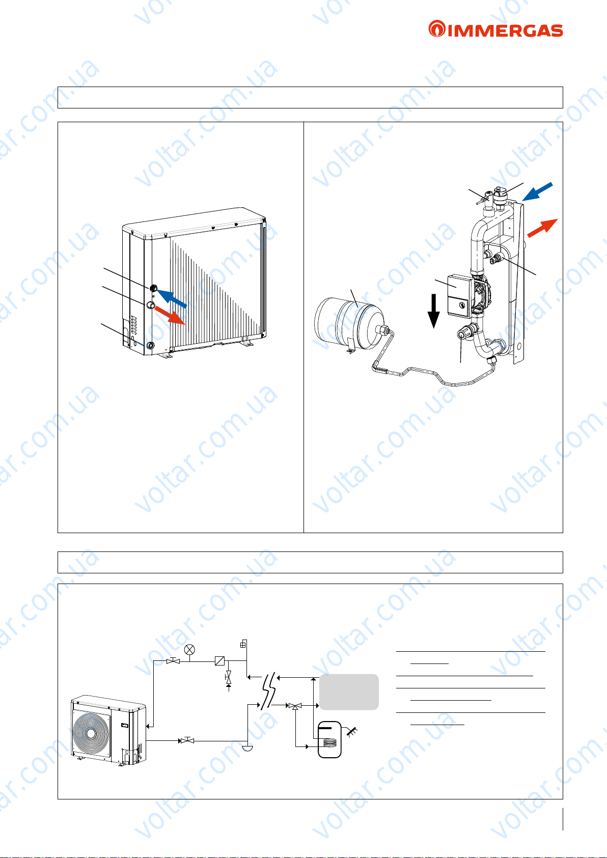
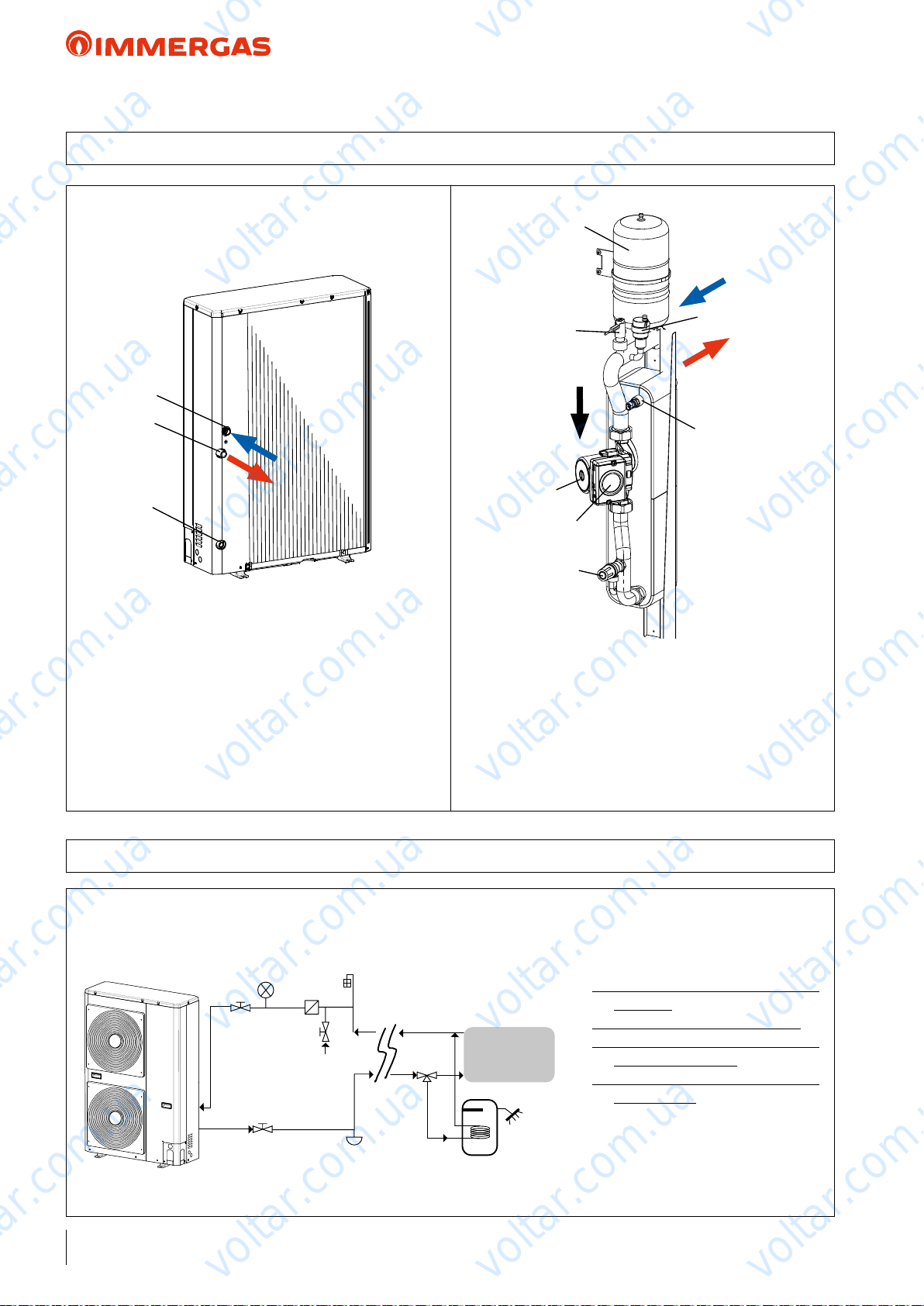
8 AUDAX TOP 6 8 ErP HYDRAULIC CIRCUIT COMPONENTS
voltar.com.ua
voltar.com.ua
1
2
3
voltar.com.ua
KEY:
1 - System return tting 1"M
2 - System ow tting 1"M
3 - Water drain
voltar.com.ua
voltar.com.ua
7
5
2
voltar.com.ua
3
KEY:
1 - Automatic air vent valve
2 - Flow switch
3 - Safety valve (outlet 1/2’)
4 - Temperature probe
5 - Circulation pump
7 - Expansion vessel
voltar.com.ua
1
voltar.com.ua
4
voltar.com.ua
voltar.com.ua
8.1 AUDAX TOP 6 8 ErP HYDRAULIC DIAGRAM
e diagram is purely indicative and not limited to the hydraulic circuit.
Also see the example on page 90-91
3
1
voltar.com.ua
1
2
6
4
3
voltar.com.ua
voltar.com.ua
7
5
8
voltar.com.ua
9
KEY:
1 - Shut-o valve
2 - Water line lters (standard)
3 - Pressure gauge (not supplied - to be
provided)
4 - Filling valve (NOT Automatic)
5 - System draining valve (in the lowest
points of the circuit)
6 - Air vent valve (in the highest points
of the circuit)
7 - 3-way valve
8 - DHW storage tank
9 - Internal utility
voltar.com.ua
25
voltar.com.ua
Page 26
1
2
3
3
voltar.com.ua
voltar.com.ua
AUDAX TOP ErP
8.2 AUDAX TOP 12 16 ErP HYDRAULIC CIRCUIT COMPONENTS
7
voltar.com.ua
voltar.com.ua
1
2
3
voltar.com.ua
KEY:
1 - System return tting 1"M
2 - System ow tting 1"M
3 - Water drain
voltar.com.ua
voltar.com.ua
2
6
voltar.com.ua
KEY:
1 - Automatic air vent valve
2 - Flow switch
3 - Safety valve (outlet 1/2’)
4 - Temperature probe
5 - Circulation pump
7 - Expansion vessel
5
3
1
4
voltar.com.ua
voltar.com.ua
voltar.com.ua
voltar.com.ua
8.3 AUDAX TOP 12 16 ErP HYDRAULIC DIAGRAM
e diagram is purely indicative and not limited to the hydraulic circuit.
Also see the example on page 90-91
26
1
voltar.com.ua
1
2
6
4
3
7
5
voltar.com.ua
voltar.com.ua
9
8
voltar.com.ua
KEY:
1 - Shut-o valve
2 - Water line lters (standard)
3 - Pressure gauge (not supplied - to be
provided)
4 - Filling valve (NOT Automatic)
5 - System draining valve (in the lowest
points of the circuit)
6 - Air vent valve (in the highest points
of the circuit)
7 - 3-way valve
8 - DHW storage tank
9 - Internal utility
voltar.com.ua
voltar.com.ua
Page 27
1
2
3
voltar.com.ua
voltar.com.ua
AUDAX TOP ErP
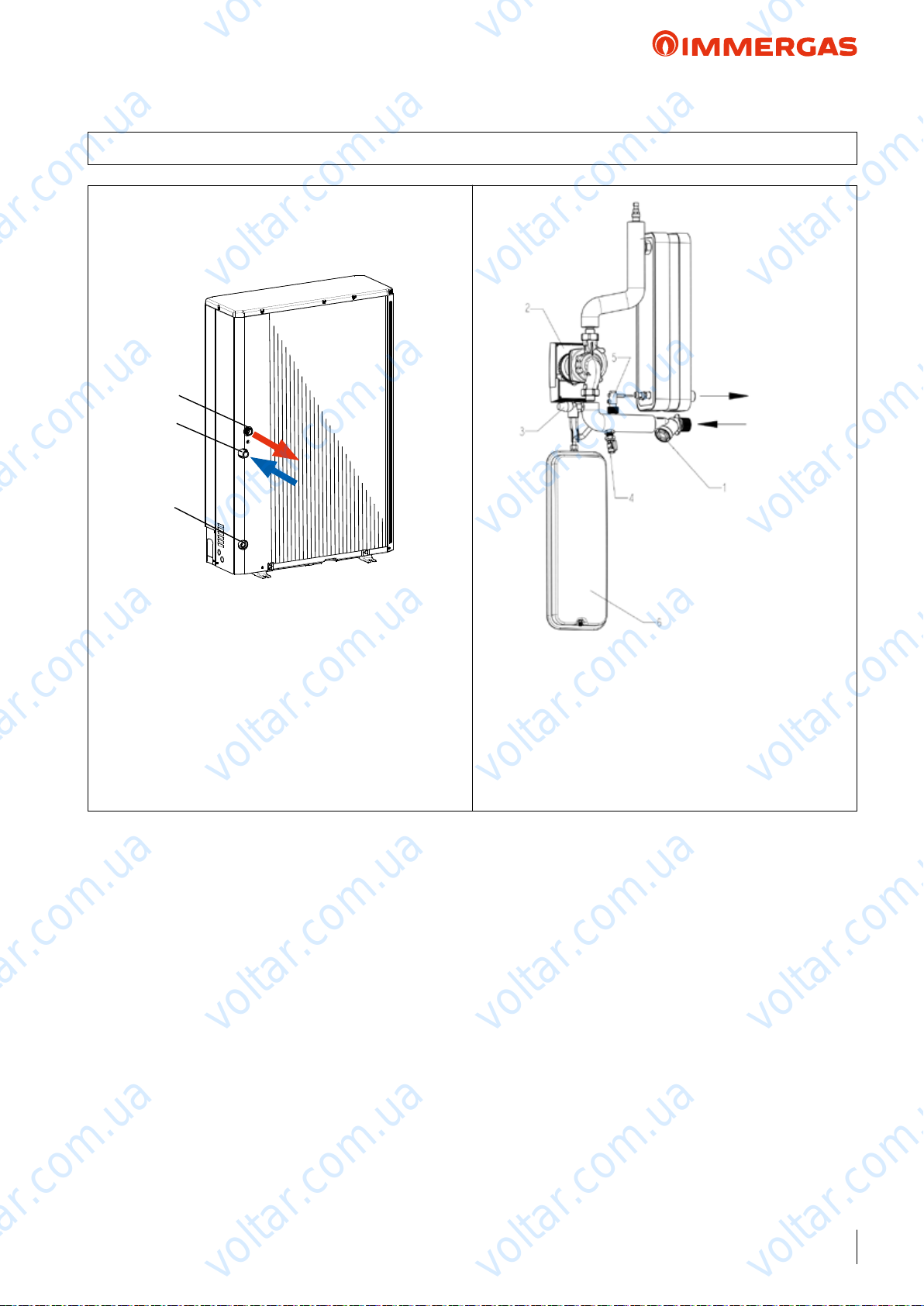
8.4 AUDAX TOP 18 21 ErP HYDRAULIC CIRCUIT COMPONENTS
voltar.com.ua
voltar.com.ua
1
2
3
voltar.com.ua
KEY:
1 - System ow tting 1''M
2 - System return tting 1"1/4 M*
3 - Water drain
*1”M Reduction standard supplied
voltar.com.ua
voltar.com.ua
OUTLET
INLET
voltar.com.ua
KEY:
1 - Mesh lter
2 - Circulation pump
3 - Safety valve
4 - Water drain valve
5 - Blade ow switch
voltar.com.ua
6 - Expansion vessel
voltar.com.ua
voltar.com.ua
voltar.com.ua
voltar.com.ua
voltar.com.ua
voltar.com.ua
voltar.com.ua
voltar.com.ua
27
voltar.com.ua
Page 28
X2
10
15
20
25
30
35
40
45
50
55
60
65
70
-25 -20 -15 -10 -5 0 5 10 15 20 25 30 35
X2
Y2
AUDAX TOP 8-12-16
voltar.com.ua
voltar.com.ua
voltar.com.ua
AUDAX TOP ErP
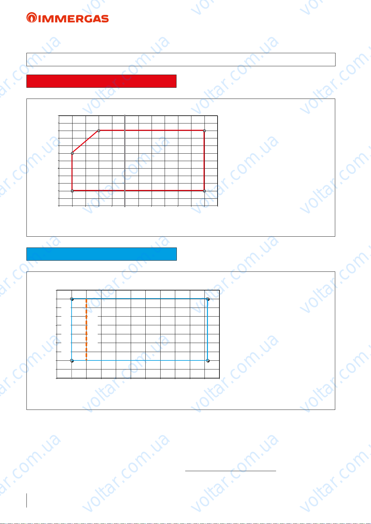
9 AUDAX TOP 6 8 12 16 ErP OPERATING LIMITS AND ANTIFREEZE FUNCTION
Central heating
70
65
60
55
50
45
40
Y2
35
30
25
20
15
10
-25 -20 -15 -10 -5 0 5 10 15 20 25 30 35
Y1
20
18
16
14
12
10
8
6
4
2
0
-5
voltar.com.ua
voltar.com.ua
Cooling
voltar.com.ua
AUDAX TOP 6
0
105
15 20 25 30 35
voltar.com.ua
KEY:
Y2 - Flow water temperature (°C)
X2 - Outdoor air temperature (°C)
voltar.com.ua
KEY:
Y1 - Flow water temperature (°C)
voltar.com.ua
40
45
X1 - Outdoor air temperature (°C)
50
voltar.com.ua
voltar.com.ua
voltar.com.ua
X1
voltar.com.ua
NOTE: AUDAX TOP ErP is equipped with antifreeze protection up to -10 °C with supply voltage. If AUDAX TOP
ErP is installed in areas having temperatures below 0 °C, it is
recommended to provide special antifreeze systems in order to
guarantee the machine's integrity, especially the water-gas heat
exchanger, when there is a blackout.
For example, insert top quality, non-hazardous antifreeze liquid
into the heating system. In this case, the instructions of the
manufacturer of this liquid must be followed scrupulously re-
28
voltar.com.ua
voltar.com.ua
garding the percentage necessary with respect to the minimum
temperature at which the system must be kept.
An aqueous solution must be made with potential pollution class
of water 2 (EN 1717:2002).
With no supply voltage and if no antifreeze liquid has been
inserted, you must drain the water from the machine.
Avoid using automatic lling systems.
voltar.com.ua
voltar.com.ua
voltar.com.ua
Page 29
10
15
20
25
30
35
40
45
50
55
60
65
70
-25 -20 -15 -10 -5 0 5 10 15 20 25 30 35
X2
Y2
AUDAX 18 TOP ErP
AUDAX 21 TOP ErP
voltar.com.ua
voltar.com.ua
voltar.com.ua
AUDAX TOP ErP
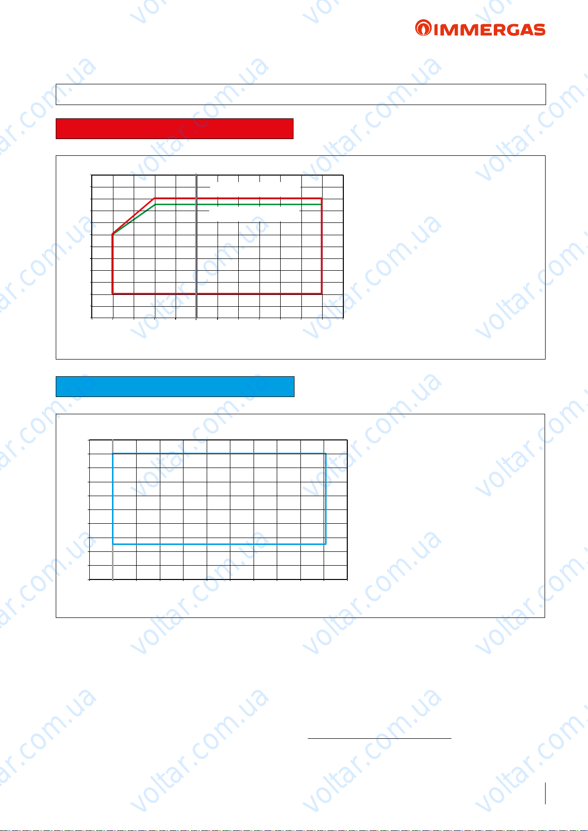
9.1 AUDAX TOP 18 21 ErP OPERATING LIMITS AND ANTIFREEZE FUNCTION
Central heating
70
65
60
55
50
45
40
Y2
35
30
25
20
15
10
-25 -20 -15 -10 -5 0 5 10 15 20 25 30 35
Y1
20
18
16
14
12
10
8
6
4
2
0
-5
0
voltar.com.ua
voltar.com.ua
Cooling
AUDAX 18 TOP ErP
AUDAX 21 TOP ErP
X2
voltar.com.ua
105
15 20 25 30 35
X1
voltar.com.ua
KEY:
Y2 - Flow water temperature (°C)
X2 - Outdoor air temperature (°C)
voltar.com.ua
KEY:
Y1 - Flow water temperature (°C)
X1 - Outdoor air temperature (°C)
voltar.com.ua
40
50
45
voltar.com.ua
voltar.com.ua
voltar.com.ua
NOTE: AUDAX TOP 18-21 ErP is equipped with antifreeze
protection comprising an electrical resistance to protect the plate
exchanger which is the most critical component with regard to
freezing. When the electrical resistance activates so does the
pump inside the AUDAX TOP 18-21 ErP, in this way, with
power supply voltage, the machine is protected up to -10°C.
If AUDAX TOP 18-21 ErP is installed in areas having temperatures below 0 °C, it is recommended to provide special antifreeze
systems in order to guarantee the machine's integrity, especially
the water-gas heat exchanger, when there is a blackout.
For example, insert top quality, non-hazardous antifreeze liquid
into the heating system.
voltar.com.ua
voltar.com.ua
In this case, the instructions of the manufacturer of this liquid
must be followed scrupulously regarding the percentage necessary
voltar.com.ua
with respect to the minimum temperature at which the system
must be kept.
An aqueous solution must be made with potential pollution class
of water 2 (EN 1717:2002).
With no supply voltage and if no antifreeze liquid has been
inserted, you must drain the water from the machine.
Avoid using automatic lling systems.
voltar.com.ua
voltar.com.ua
29
voltar.com.ua
Page 30
voltar.com.ua
voltar.com.ua
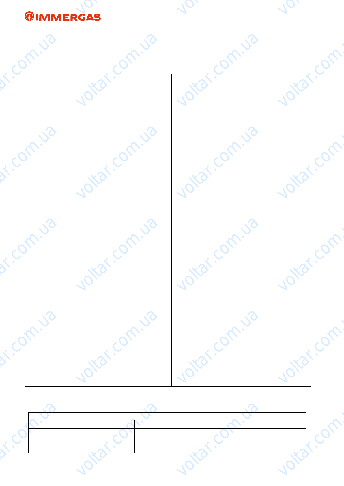
AUDAX TOP 6 ErP
10 AUDAX TOP 6 ErP TECHNICAL DATA
Central heating circuit
Power in CH mode with water set at 35 °C
Power in CH mode with water set at 45 °C
Power in CH mode with water set at 55 °C
CH mode COP with water set at 35 °C
CH mode COP with water set at 45 °C
CH mode COP with water set at 55 °C
Min/max heat power with water set at 35 °C
Min/max heat power with water set at 45 °C
Min/max heat power with water set at 55 °C
Flow temperature range °C 20 / 60
Outdoor temperature heating operation limits °C -20 / 30
voltar.com.ua
(1)
kW 5.76
(2)
kW 5.76
(3)
kW 5.43
(1)
4.28
(2)
3.05
(3)
2.77
(1)
kW 1.08 / 6.14
(2)
kW 1.06 / 6.04
(3)
kW 1.02 / 5.58
voltar.com.ua
voltar.com.ua
voltar.com.ua
Cooling circuit
Power in cooling mode with water set at 18 °C
Power in cooling mode with water set at 7 °C
Cooling mode EER with water set at 18 °C
Cooling mode EER with water set at 7 °C
Min/max cooling capacity with water set at 18 °C
Min/max cooling capacity with water set at 7 °C
Flow temperature range °C 4 / 18
Outdoor temperature Cooling operation limits °C 5 / 46
General data
Max system operating pressure bar 3
Head available on the system with 1500 l/h flow rate kPa (m H2O) 40 (4.08)
Expansion vessel capacity l 2
Water circuit content l 1.0
C.H. sound power level dB(A) 62
Appliance electric protection rating IP X4
Electric supply voltage V - Hz 230 - 50
Permitted voltage range V 207 - 253
Maximum absorbed power W 2000
Maximum absorbed current A 11
Fuse inserted A 16 - Type B
Refrigerant fluid load (R410A)* g 1350
Heat Pump weight kg 61
voltar.com.ua
voltar.com.ua
voltar.com.ua
(1)
kW 7.04
(2)
kW 4.73
(1)
(2)
(1)
kW 1.20 / 7.49
(2)
voltar.com.ua
kW 0.73 / 5.33
voltar.com.ua
voltar.com.ua
voltar.com.ua
3.70
3.00
voltar.com.ua
voltar.com.ua
* Hermetically sealed system.
THE REPORTED DATA REFERS TO THE FOLLOWING CONDITIONS (in compliance with EN 14511)
ROOM C.H. MODE (°C) COOLING MODE (°C)
Room Antifreeze WATER (F/R)
Room Antifreeze WATER (F/R)
Room Antifreeze WATER (F/R)
30
(1)
- AIR (db/wb) 35/30 - 7/6 18/23 - 35 (db)
(2)
- AIR (db/wb) 45/40 - 7/6 7/12 - 35 (db)
(3)
- AIR (db/wb) 55/47 - 7/6
voltar.com.ua
voltar.com.ua
:
voltar.com.ua
Page 31
voltar.com.ua
voltar.com.ua
AUDAX TOP 6 ErP
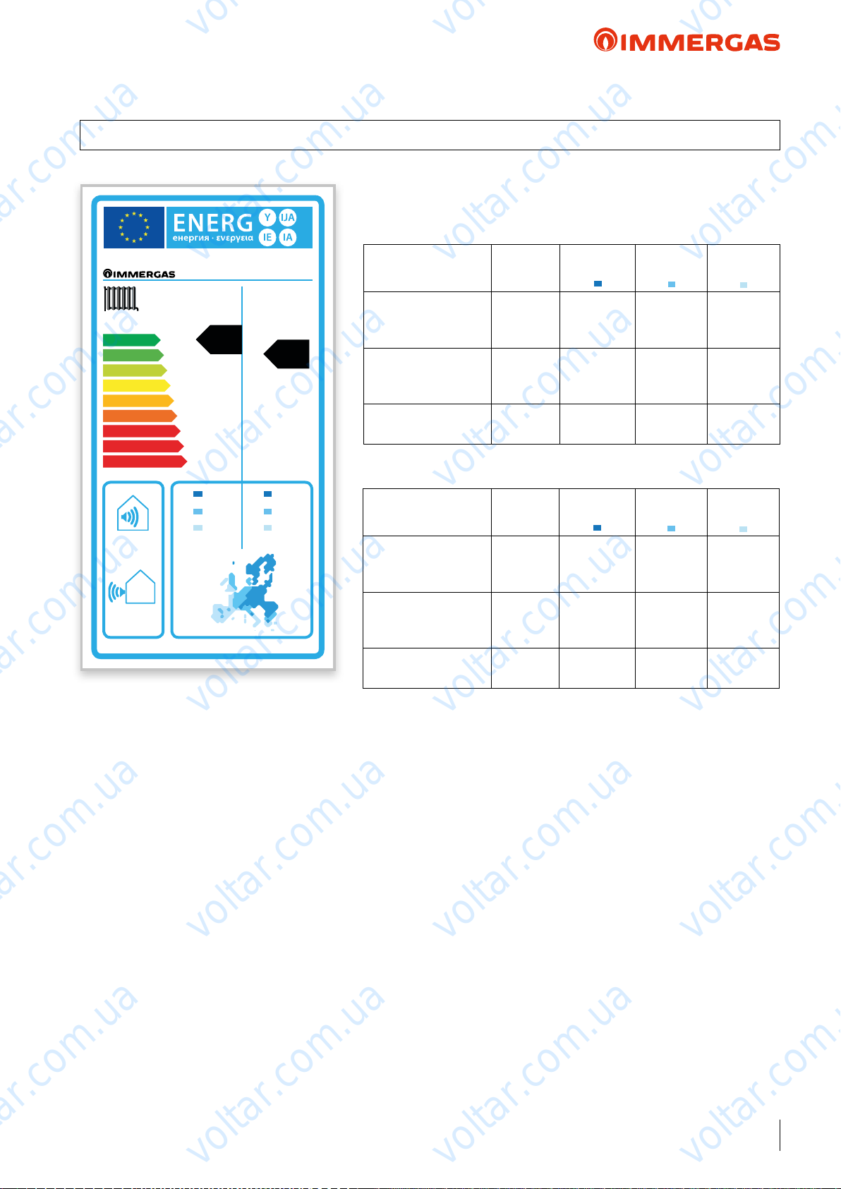
11 PRODUCT FICHE REGULATION 811/2013
AUDAX TOP ErP
Low temperature (30/35)
voltar.com.ua
AUDAX TOP 6 ErP
Parameter Value
voltar.com.ua
Colder
zones
Average
zones
voltar.com.ua
Hotter
voltar.com.ua
zones
A
A
A
B
C
D
E
F
G
62
55 °C 35 °C
++
+
dB
dB
++
A
voltar.com.ua
6.65
4.22 4.92
3.79
kW kW
A
+
7.75
4.06
Annual energy
consumption for the
heating function (QHE)
Room central heating
seasonal eciency (η
Nominal heat output kW 7.75 4.92 4.06
Average temperature (47/55)
Parameter Value
Annual energy
consumption for the
heating function (QHE)
Room central heating
seasonal eciency (η
Nominal heat output kW 6.65 4.22 3.79
voltar.com.ua
kWh/year 5927 2806 1084
ηs % 120 141 194
)
s
Colder
zones
kWh/year 5431 2571 1085
ηs % 112 132 181
)
s
Average
zones
voltar.com.ua
Hotter
zones
voltar.com.ua
voltar.com.ua
voltar.com.ua
voltar.com.ua
voltar.com.ua
voltar.com.ua
voltar.com.ua
voltar.com.ua
31
voltar.com.ua
Page 32
voltar.com.ua
voltar.com.ua
AUDAX TOP 6 ErP
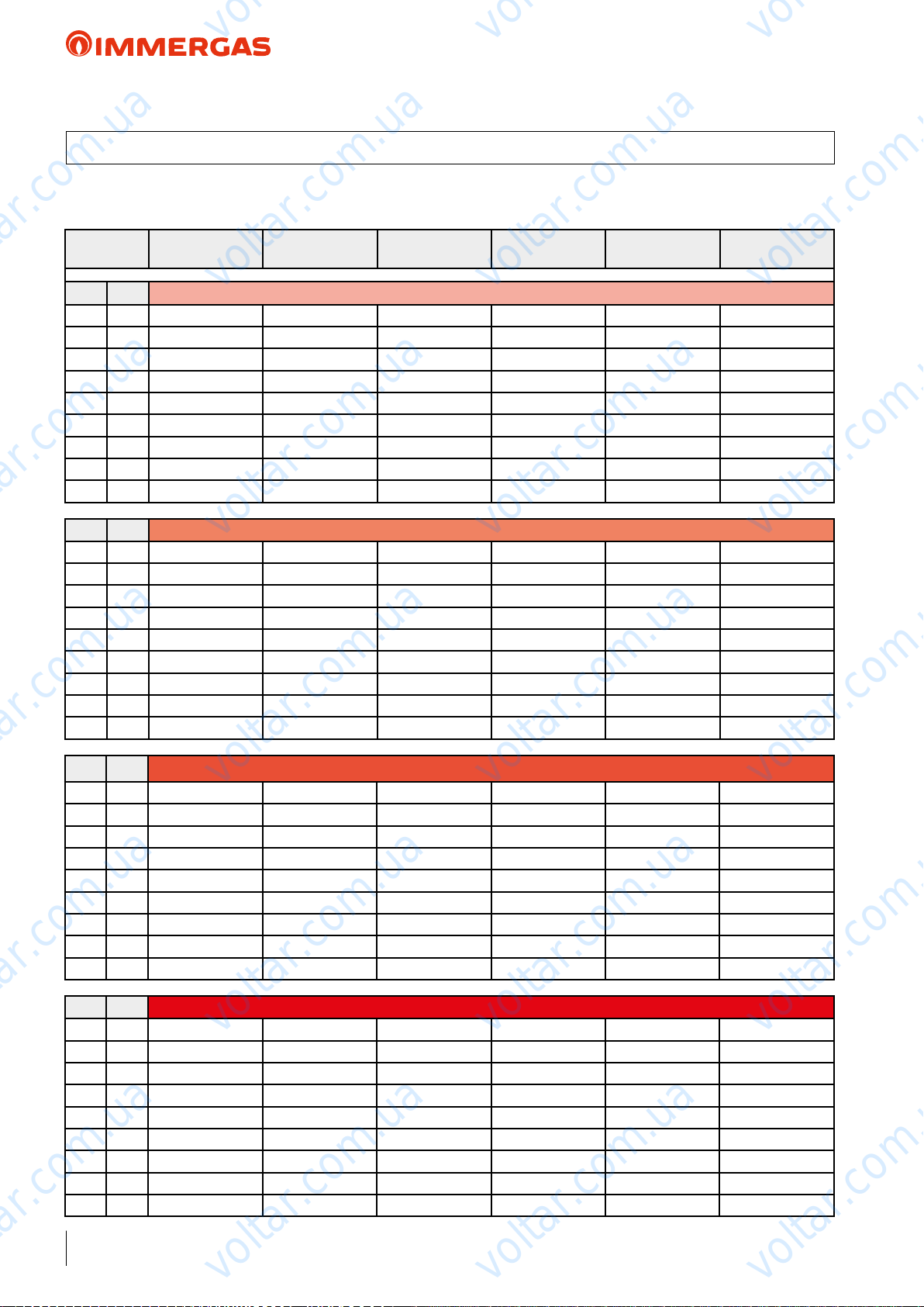
12 AUDAX TOP 6 ErP ''POWER'' AND ''COP'' CENTRAL HEATING
• TOL = -20 °C
voltar.com.ua
Air
temp. °C
d.b. (w.b.) Water ow temperature 35 °C
20 (19) 7.98 1.49 8.42 6.07 6.49 5.73
10 (9) 6.32 1.18 6.67 4.63 4.96 4.38
7 (6) 5.76 1.08 6.14 4.28 4.49 3.97
2 (1) 4.20 0.78 4.27 3.07 3.29 2.94
0 (-1) 3.99 0.74 4.06 2.97 3.18 2.84
-3 (-4) 3.75 0.70 3.82 2.77 2.97 2.65
-7 (-8) 3.44 0.64 3.50 2.51 2.69 2.4
-15 (-16) 3.20 0.60 3.26 2.31 2.47 2.21
-20 (-21) 3.00 0.45 3.11 2.06 2.10 2.00
d.b. (w.b.) Water ow temperature 45 °C
20 (19) 7.70 1.41 8.20 3.77 4.07 3.66
10 (9) 6.24 1.14 6.49 3.18 3.43 3.08
7 (6) 5.76 1.06 6.04 3.05 3.24 2.91
2 (1) 4.20 0.79 4.22 2.51 2.78 2.40
0 (-1) 4.00 0.72 4.02 2.39 2.59 2.29
-3 (-4) 3.76 0.69 3.80 2.31 2.51 2.21
-7 (-8) 3.45 0.64 3.50 2.20 2.39 2.11
-15 (-16) 3.20 0.59 3.24 2.13 2.31 2.03
-20 (-21) 1.44 0.44 1.44 1.82 2.02 1.82
Output (kW)
Nom
Output (kW)
Min
Output (kW)
Max
voltar.com.ua
voltar.com.ua
COP (EN 14511)
Nom
COP (EN 14511)
Min
COP (EN 14511)
Max
voltar.com.ua
voltar.com.ua
voltar.com.ua
voltar.com.ua
d.b. (w.b.) Water ow temperature 55 °C
20 (19) 6.87 1.35 7.05 3.23 3.43 3.18
10 (9) 5.98 1.10 6.10 2.72 2.93 2.70
7 (6) 5.40 1.02 5.58 2.58 2.78 2.53
2 (1) 4.19 0.78 4.19 2.26 2.44 2.20
0 (-1) 3.97 0.70 4.00 2.14 2.31 2.07
-3 (-4) 3.70 0.67 3.75 2.04 2.20 1.97
-7 (-8) 3.28 0.61 3.33 1.90 2.06 1.85
-15 (-16) 1.58 0.56 1.58 1.76 1.95 1.76
-20 (-21) 0.43 0.43 0.43 1.64 1.64 1.64
d.b. (w.b.) Water ow temperature 60 °C
20 (19) 6.07 1.19 6.07 2.79 2.96 2.79
10 (9) 5.32 0.99 5.32 2.37 2.53 2.37
7 (6) 5.00 0.93 5.07 2.25 2.41 2.23
2 (1) 3.87 0.72 4.01 1.99 2.13 1.92
0 (-1) 3.68 0.68 3.80 1.89 2.02 1.82
-3 (-4) 3.39 0.63 3.48 1.80 1.93 1.73
-7 (-8) 3.01 0.56 3.06 1.69 1.80 1.62
-15 (-16) 0.52 0.52 0.52 1.71 1.71 1.71
-20 (-21) 0.39 0.39 0.39 1.53 1.53 1.53
voltar.com.ua
voltar.com.ua
voltar.com.ua
voltar.com.ua
voltar.com.ua
voltar.com.ua
32
voltar.com.ua
voltar.com.ua
voltar.com.ua
Page 33
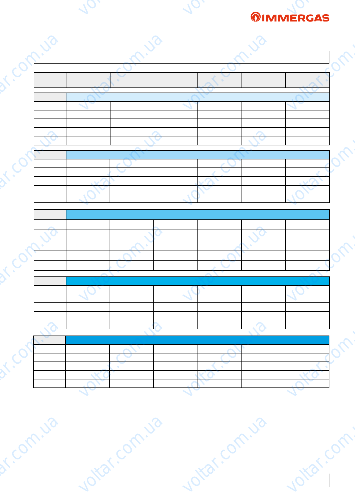
voltar.com.ua
voltar.com.ua
AUDAX TOP 6 ErP
12.1 AUDAX TOP 6 ErP ''POWER'' AND ''EER'' IN COOLING
voltar.com.ua
Air
temp. °C
d.b. Water ow temperature 18 °C
45 6.20 1.00 6.50 2.74 5.54 2.74
35 7.04 1.20 7.49 3.70 7.58 3.35
25 8.08 1.38 8.08 5.04 10.58 5.04
15 1.72 1.57 1.72 12.71 14.13 12.71
5 1.75 1.75 1.75 16.06 16.06 16.06
d.b. Water ow temperature 15 °C
45 5.64 0.89 6.01 2.60 5.25 2.55
35 6.37 1.07 6.90 3.42 7.14 3.16
25 7.41 1.24 7.41 4.72 9.86 4.72
15 1.56 1.42 1.56 11.68 12.97 11.68
5 1.59 1.59 1.59 14.75 14.75 14.75
d.b. Water ow temperature 10 °C
45 4.71 0.70 5.18 2.35 4.76 2.24
35 5.33 0.86 5.92 3.10 6.40 2.85
25 6.29 1.01 6.29 4.19 8.65 4.19
Output (kW)
Nom
Output (kW)
Min
voltar.com.ua
voltar.com.ua
Output (kW)
Max
EER (EN 14511)
Nom
EER (EN 14511)
Min
EER (EN 14511)
Max
voltar.com.ua
voltar.com.ua
voltar.com.ua
voltar.com.ua
15 1.28 1.16 1.28 9.95 11.05 9.95
5 1.44 1.31 1.44 11.32 12.57 11.32
d.b. Water ow temperature 7 °C
45 4.15 0.59 4.69 2.21 4.47 2.05
35 4.73 0.73 5.33 3.00 5.96 2.66
25 5.61 0.88 5.61 3.88 7.93 3.88
15 1.11 1.01 1.11 8.91 9.90 8.91
5 1.26 1.15 1.26 10.14 11.27 10.14
d.b. Water ow temperature 5 °C
45 3.78 0.51 4.36 2.11 4.28 1.92
35 4.28 0.65 4.94 2.78 5.66 2.53
25 5.16 0.79 5.16 3.66 7.45 3.66
15 1.00 0.91 1.00 8.22 9.13 8.22
5 1.14 1.04 1.14 9.36 10.4 9.36
voltar.com.ua
voltar.com.ua
voltar.com.ua
voltar.com.ua
voltar.com.ua
voltar.com.ua
voltar.com.ua
voltar.com.ua
33
voltar.com.ua
Page 34
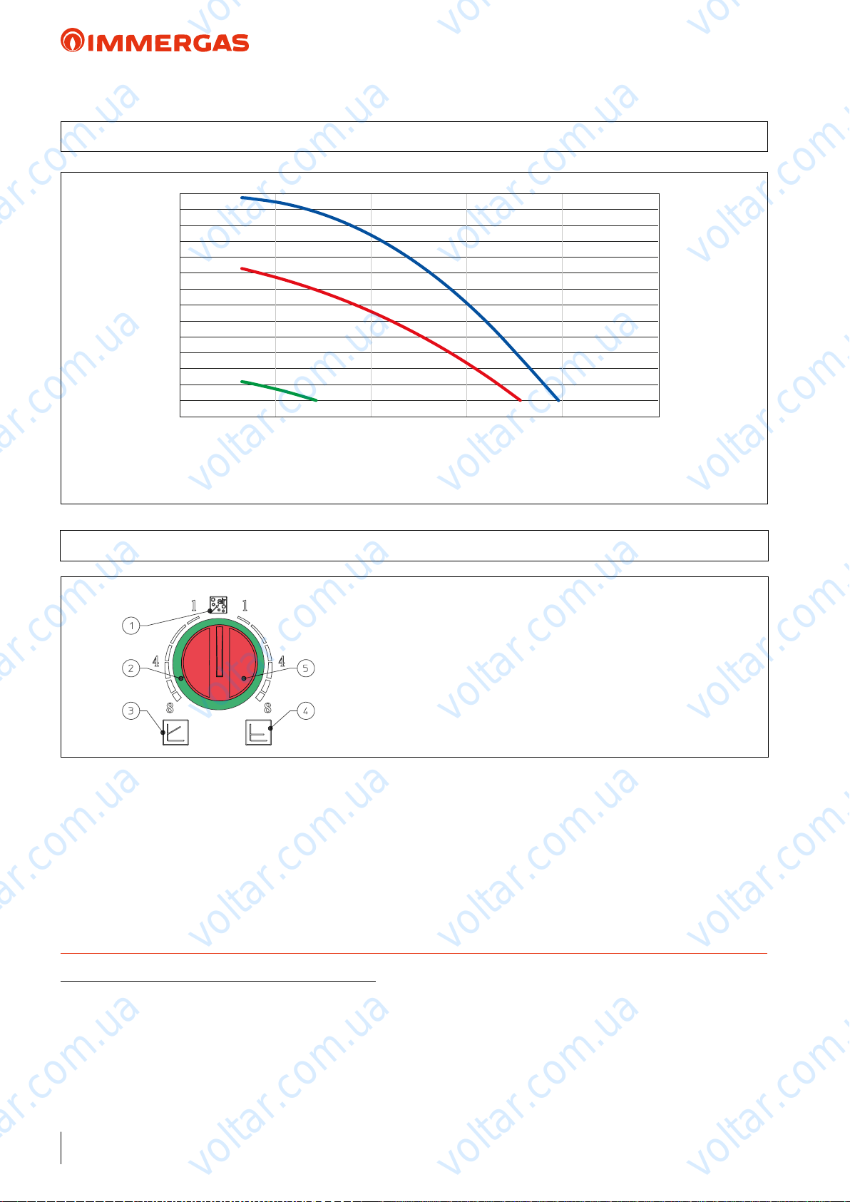
voltar.com.ua
voltar.com.ua
AUDAX TOP 6 ErP
13 GRAPH OF AUDAX TOP 6 ErP PUMP FLOW RATE/HEAD
75
70
65
60
Head (kPa)
55
50
45
40
35
30
25
20
15
10
voltar.com.ua
5
0 500 10 00 1500 2000
voltar.com.ua
voltar.com.ua
voltar.com.ua
2500
Flow rate l/h
All curves have been dened in constant pressure mode with minimum, intermediate and maximum speed.
13.1 AUDAX TOP 6 ErP PUMP SETTINGS AND CONFIGURATIONS
AUDAX TOP 6 ErP range boilers are supplied with a low power
consumption pump with variable speed control.
e circulating pump is equipped with electronic control to set
advanced functions.
Constant head (∆P C) (Ref. 4 above g.) default setting. e
circulator pump maintains the pressure level (head) constant as
the system heat demand decreases (ow rate reduction). With
these settings, the pump is suitable for all oor systems.
voltar.com.ua
KEY:
1 - Automatic vent mode operation
2 - Light ring to indicate the operating status
3 - Proportional head operation
4 - Constant head operation
5 - Operating mode selector switch
voltar.com.ua
Proportional head (∆P V) (Ref. 3 above g.). is allows
the pressure level (head) to be proportionally reduced as the
system heat demand decreases (ow rate reduction). anks to
this function, the electric power consumption of the circulator
pump is reduced further: the energy (power) used by the pump
decreases according to the pressure level and ow rate. With
this setting, the pump guarantees optimal performance in most
heating systems, proving particularly suitable in single-pipe and
two-pipe installations.
voltar.com.ua
voltar.com.ua
voltar.com.ua
voltar.com.ua
voltar.com.ua
TECHNICAL NOTE: System minimum water content:
To facilitate proper execution of the AUDAX TOP ErP heat pump defrost cycles, a minimum water content in the system is required,
which must be: 6 l/kW of the machine's power for any type of system. e ywheel guarantees normal operation of AUDAX TOP ErP
with systems divided into zones (with variable water content in circulation). e ywheel also guarantees proper operation with fan coils
used for cooling (a condition in which the ow temperature is very low and has signicant heat load variations that vary the number of
active fan coils). It is also important to check that the dehumidier line has a minimum of 3 l/kW of the machine (dehumidier hydraulic
circuit connection).
N.B.: for inertial tanks codes supplied by Immergas, refer to page 107.
34
voltar.com.ua
voltar.com.ua
voltar.com.ua
voltar.com.ua
voltar.com.ua
Page 35
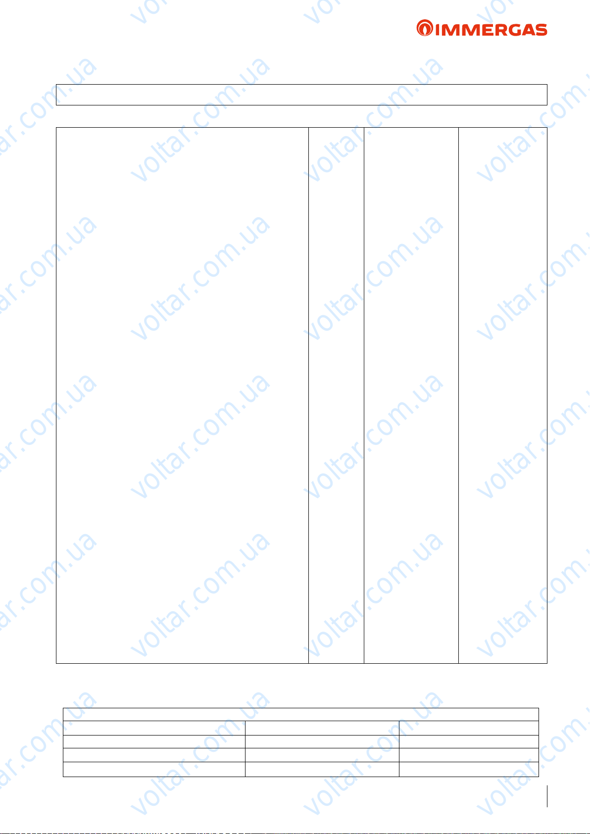
voltar.com.ua
voltar.com.ua
AUDAX TOP 8 ErP
14 AUDAX TOP 8 ErP TECHNICAL DATA
Central heating circuit
Power in CH mode with water set at 35 °C
Power in CH mode with water set at 45 °C
Power in CH mode with water set at 55 °C
CH mode COP with water set at 35 °C
CH mode COP with water set at 45 °C
CH mode COP with water set at 55 °C
Min/max heat power with water set at 35 °C
Min/max heat power with water set at 45 °C
Min/max heat power with water set at 55 °C
Flow temperature range °C 20 / 60
Outdoor temperature heating operation limits °C - 20 / 30
voltar.com.ua
(1)
kW 7.16
(2)
kW 7.36
(3)
kW 7.25
(1)
3.97
(2)
3.19
(3)
2.81
(1)
kW 1.34 / 8.00
(2)
kW 1.32 / 7.92
(3)
kW 1.25 / 7.46
voltar.com.ua
voltar.com.ua
voltar.com.ua
Cooling circuit
Power in cooling mode with water set at 18 °C
Power in cooling mode with water set at 7 °C
Cooling mode EER with water set at 18 °C
Cooling mode EER with water set at 7 °C
Min/max cooling capacity with water set at 18 °C
Min/max cooling capacity with water set at 7 °C
Flow temperature range°C4 / 18
Outdoor temperature Cooling operation limits °C 0 / 46
General data
Max system operating pressure bar 3
Head available on the system with 1500 l/h flow rate kPa (m H2O) 48 (4.89)
Expansion vessel capacity l 2
Water circuit content l 1.2
C.H. sound power level dB(A) 64
Appliance electric protection rating IP X4
Electric supply voltage V - Hz 230 - 50
Permitted voltage range V 207 - 253
Maximum absorbed power W 2700
Maximum absorbed current A 14.5
Fuse inserted A 16 - Type B
Refrigerant fluid load (R410A)* g 1810
Heat Pump weight kg 69
voltar.com.ua
voltar.com.ua
voltar.com.ua
(1)
kW 7.84
(2)
kW 5.84
(1)
3.99
(2)
2.98
(1)
(2)
voltar.com.ua
kW 0.97 / 8.44
kW 0.50 / 5.80
voltar.com.ua
voltar.com.ua
voltar.com.ua
voltar.com.ua
voltar.com.ua
* Hermetically sealed system.
THE REPORTED DATA REFERS TO THE FOLLOWING CONDITIONS (in compliance with EN 14511)
ROOM C.H. MODE (°C) COOLING MODE (°C)
Room Antifreeze WATER (F/R)
Room Antifreeze WATER (F/R)
Room Antifreeze WATER (F/R)
voltar.com.ua
(1)
- AIR (db/wb) 35/30 - 7/6 18/23 - 35 (db)
(2)
- AIR (db/wb) 45/40 - 7/6 7/12 - 35 (db)
(3)
- AIR (db/wb) 55/47 - 7/6
voltar.com.ua
:
35
voltar.com.ua
Page 36
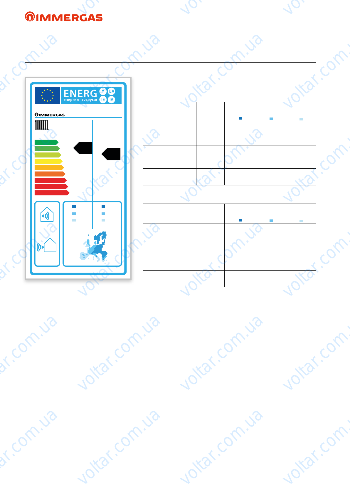
voltar.com.ua
voltar.com.ua
AUDAX TOP 8 ErP
15 PRODUCT FICHE REGULATION 811/2013
AUDAX TOP 8 ErP
Low temperature (30/35)
voltar.com.ua
AUDAX TOP 8 ErP
Parameter Value
voltar.com.ua
Colder
zones
Average
zones
voltar.com.ua
Hotter
voltar.com.ua
zones
A
A
A
B
C
D
E
F
G
64
55 °C 35 °C
++
+
+
A
A
dB
dB
voltar.com.ua
6.59
4.65 4.56
4.83
kW kW
6.46
5.09
Annual energy
consumption for the
heating function (Q
Room central heating
seasonal eciency (η
Nominal heat output kW 6.46 4.56 5.09
Average temperature (47/55)
Parameter Value
Annual energy
consumption for the
heating function (QHE)
Room central heating
seasonal eciency (η
Nominal heat output kW 6.59 4.65 4.83
kWh/year 5381 3088 1624
)
HE
ηs % 110 118 163
)
s
voltar.com.ua
Colder
zones
kWh/year 5867 3367 1649
ηs % 103 111 152
)
s
Average
zones
voltar.com.ua
Hotter
zones
voltar.com.ua
voltar.com.ua
voltar.com.ua
voltar.com.ua
voltar.com.ua
voltar.com.ua
36
voltar.com.ua
voltar.com.ua
voltar.com.ua
Page 37
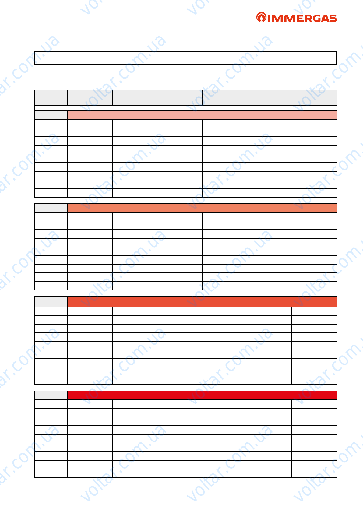
voltar.com.ua
voltar.com.ua
AUDAX TOP 8 ErP
16 AUDAX TOP 8 ErP ''POWER'' AND ''COP'' CENTRAL HEATING
• TOL = -20 °C
voltar.com.ua
Air
temp. °C
d.b. (w.b.) Water ow temperature 35 °C
20 (19) 9.87 1.84 10.97 5.46 5.84 4.81
10 (9) 7.82 1.46 8.69 4.26 4.56 3.76
7 (6) 7.16 1.34 8.00 3.97 4.17 3.44
2 (1) 5.12 1.01 5.52 2.99 3.27 2.64
0 (-1) 4.74 0.96 5.24 2.94 3.21 2.54
-3 (-4) 4.36 0.88 4.83 2.81 3.04 2.38
-7 (-8) 3.76 0.78 4.20 2.63 2.81 2.10
-15 (-16) 3.20 0.73 3.70 2.47 2.64 2.00
-20 (-21) 1.76 0.56 1.76 2.46 2.50 2.46
d.b. (w.b.) Water ow temperature 45 °C
20 (19) 10.02 1.82 10.75 4.34 4.73 3.89
10 (9) 8.03 1.44 8.57 3.44 3.74 3.08
7 (6) 7.36 1.32 7.92 3.19 3.45 2.84
2 (1) 5.15 0.99 5.48 2.55 2.69 2.11
0 (-1) 4.81 0.95 5.20 2.42 2.55 2.01
-3 (-4) 4.45 0.87 4.78 2.34 2.51 1.85
-7 (-8) 3.85 0.76 4.00 2.23 2.45 1.70
-15 (-16) 3.35 0.71 3.60 2.11 2.26 1.65
-20 (-21) 1.27 0.57 1.27 2.00 1.96 2.00
Output (kW)
Nom
Output (kW)
Min
voltar.com.ua
voltar.com.ua
Output (kW)
Max
COP (EN 14511)
Nom
COP (EN 14511)
Min
COP (EN 14511)
Max
voltar.com.ua
voltar.com.ua
voltar.com.ua
voltar.com.ua
d.b. (w.b.) Water ow temperature 55 °C
20 (19) 9.05 1.68 10.05 3.49 3.73 3.20
10 (9) 7.25 1.35 8.05 2.87 3.07 2.68
7 (6) 6.70 1.25 7.46 2.30 2.50 2.12
2 (1) 4.86 0.96 5.24 2.20 2.40 2.00
0 (-1) 4.50 0.91 4.98 2.08 2.35 1.85
-3 (-4) 4.23 0.84 4.59 1.97 2.19 1.76
-7 (-8) 3.60 0.74 3.96 1.86 2.09 1.65
-15 (-16) 0.83 0.69 0.83 1.88 1.98 1.88
-20 (-21) 0.49 0.49 0.49 1.80 1.80 1.80
d.b. (w.b.) Water ow temperature 60 °C
20 (19) 3.95 1.41 4.81 2.71 2.74 2.69
10 (9) 3.25 1.15 3.95 2.26 2.28 2.24
7 (6) 3.04 1.08 3.70 2.12 2.14 2.10
2 (1) 2.35 0.84 2.86 1.86 1.88 1.85
0 (-1) 2.24 0.79 2.72 1.76 1.78 1.74
-3 (-4) 2.06 0.73 2.51 1.68 1.69 1.66
-7 (-8) 1.83 0.65 2.22 1.57 1.58 1.55
-15 (-16) 0.59 0.59 0.59 1.50 1.50 1.50
-20 (-21) 0.40 0.40 0.40 1.41 1.41 1.41
voltar.com.ua
voltar.com.ua
voltar.com.ua
voltar.com.ua
voltar.com.ua
voltar.com.ua
voltar.com.ua
voltar.com.ua
37
voltar.com.ua
Page 38
voltar.com.ua
voltar.com.ua
AUDAX TOP 8 ErP
16.1 AUDAX TOP 8 ErP ''POWER'' AND ''EER'' IN COOLING
voltar.com.ua
Air
temp. °C
d.b. Water ow temperature 18 °C
45 0.85 0.85 0.85 4.62 4.62 4.62
35 7.84 0.97 8.44 3.99 6.24 3.80
25 8.86 1.08 9.46 5.62 9.02 5.37
15 9.80 1.20 10.47 8.24 12.46 7.87
5 10.73 1.31 11.46 10.86 16.89 10.37
d.b. Water ow temperature 15 °C
45 6.17 0.74 6.77 2.70 4.12 2.62
35 7.04 0.84 7.72 3.66 5.58 3.56
25 7.98 0.94 8.66 5.24 8.04 5.02
15 8.83 1.04 9.59 7.66 11.19 7.33
5 9.68 1.14 10.51 10.35 15.23 9.85
d.b. Water ow temperature 10 °C
45 5.04 0.55 5.70 2.37 3.28 2.29
35 5.77 0.63 6.52 3.25 4.50 3.15
25 6.51 0.71 7.33 4.61 6.39 4.44
Output (kW)
Nom
voltar.com.ua
voltar.com.ua
Output (kW)
Min
Output (kW)
Max
EER (EN 14511)
Nom
EER (EN 14511)
Min
EER (EN 14511)
Max
voltar.com.ua
voltar.com.ua
voltar.com.ua
voltar.com.ua
15 7.22 0.78 8.12 6.68 9.07 6.43
5 7.92 0.86 8.91 9.52 12.45 8.99
d.b. Water ow temperature 7 °C
45 4.37 0.44 5.06 2.17 2.77 2.09
35 5.84 0.50 5.80 2.98 3.85 2.91
25 5.63 0.56 6.53 4.23 5.40 4.08
15 6.25 0.63 7.24 6.10 7.80 5.89
5 6.86 0.69 7.95 9.01 10.78 8.47
d.b. Water ow temperature 5 °C
45 3.91 0.36 4.63 2.03 2.44 1.96
35 4.50 0.42 5.32 2.84 3.41 2.74
25 5.05 0.47 6.00 3.97 4.75 3.85
15 5.60 0.52 6.66 5.71 6.95 5.53
5 6.16 0.57 7.31 8.68 9.67 8.12
voltar.com.ua
voltar.com.ua
voltar.com.ua
voltar.com.ua
voltar.com.ua
voltar.com.ua
38
voltar.com.ua
voltar.com.ua
voltar.com.ua
Page 39
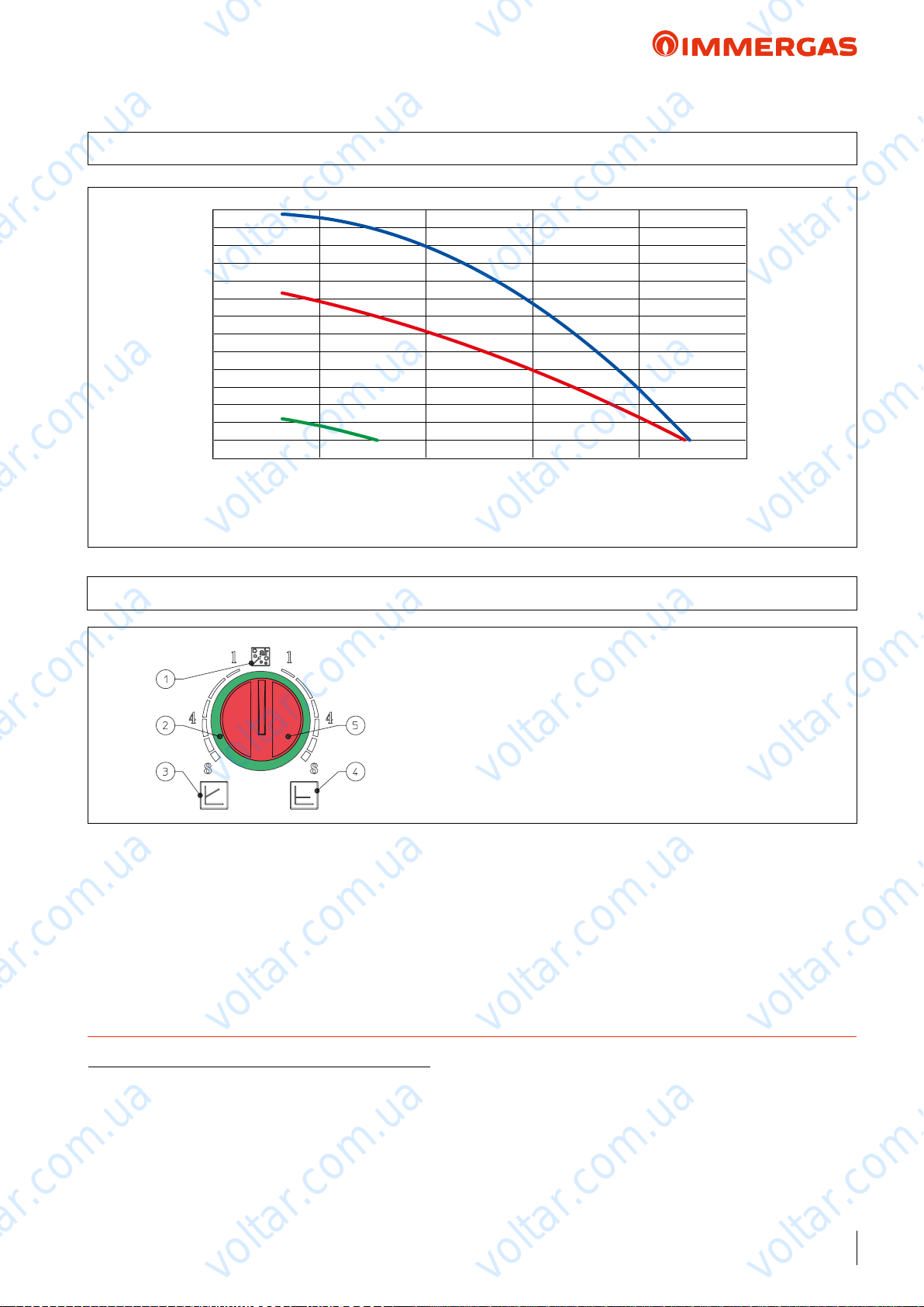
voltar.com.ua
voltar.com.ua
AUDAX TOP 8 ErP
17 GRAPH OF AUDAX TOP 8 ErP PUMP FLOW RATE/HEAD
75
70
65
60
55
voltar.com.ua
50
45
40
35
30
25
Head (kPa)
20
15
10
5
0 500 1000 1500 2000 2500
voltar.com.ua
voltar.com.ua
voltar.com.ua
Flow rate l/h
All curves have been dened in constant pressure mode with minimum, intermediate and maximum speed.
17.1 AUDAX TOP 8 ErP PUMP SETTINGS AND CONFIGURATIONS
AUDAX TOP 8 ErP range boilers are supplied with a low power
consumption pump with variable speed control.
e circulating pump is equipped with electronic control to set
advanced functions.
Constant head (∆P C) (Ref. 4 above g.) default setting. e
circulator pump maintains the pressure level (head) constant as
the system heat demand decreases (ow rate reduction). With
these settings, the pump is suitable for all oor systems.
voltar.com.ua
KEY:
1 - Automatic vent mode operation
2 - Light ring to indicate the operating status
3 - Proportional head operation
4 - Constant head operation
5 - Operating mode selector switch
voltar.com.ua
Proportional head (∆P V) (Ref. 3 above g.). is allows
the pressure level (head) to be proportionally reduced as the
system heat demand decreases (ow rate reduction). anks to
this function, the electric power consumption of the circulator
pump is reduced further: the energy (power) used by the pump
decreases according to the pressure level and ow rate. With
this setting, the pump guarantees optimal performance in most
heating systems, proving particularly suitable in single-pipe and
two-pipe installations.
voltar.com.ua
voltar.com.ua
voltar.com.ua
voltar.com.ua
voltar.com.ua
TECHNICAL NOTE: System minimum water content:
To facilitate proper execution of the AUDAX TOP ErP heat pump defrost cycles, a minimum water content in the system is required,
which must be: 6 l/kW of the machine's power for any type of system. e ywheel guarantees normal operation of AUDAX TOP ErP
with systems divided into zones (with variable water content in circulation). e ywheel also guarantees proper operation with fan coils
used for cooling (a condition in which the ow temperature is very low and has signicant heat load variations that vary the number of
active fan coils). It is also important to check that the dehumidier line has a minimum of 3 l/kW of the machine (dehumidier hydraulic
circuit connection).
N.B.: for inertial tanks codes supplied by Immergas, refer to page 107.
voltar.com.ua
voltar.com.ua
voltar.com.ua
voltar.com.ua
39
voltar.com.ua
Page 40
voltar.com.ua
voltar.com.ua
AUDAX TOP 12 ErP
18 AUDAX TOP 12 ErP TECHNICAL DATA
Central heating circuit
Power in CH mode with water set at 35 °C
Power in CH mode with water set at 45 °C
Power in CH mode with water set at 55 °C
CH mode COP with water set at 35 °C
CH mode COP with water set at 45 °C
CH mode COP with water set at 55 °C
Min/max heat power with water set at 35 °C
Min/max heat power with water set at 45 °C
Min/max heat power with water set at 55 °C
Flow temperature range °C 20 / 60
Outdoor temperature heating operation limits °C - 20 / 30
voltar.com.ua
(1)
kW 11.86
(2)
kW 12.91
(3)
kW 10.87
(1)
3.95
(2)
3.03
(3)
2.68
(1)
kW 3.61 / 15.45
(2)
kW 3.47 / 12.95
(3)
kW 3.36 / 11.50
voltar.com.ua
voltar.com.ua
voltar.com.ua
Cooling circuit
Power in cooling mode with water set at 18 °C
Power in cooling mode with water set at 7 °C
Cooling mode EER with water set at 18 °C
Cooling mode EER with water set at 7 °C
Min/max cooling capacity with water set at 18 °C
Min/max cooling capacity with water set at 7 °C
Flow temperature range°C 4 / 18
Outdoor temperature Cooling operation limits °C 0 / 46
General data
Max system operating pressure bar 3
Head available on the system with 2500 l/h flow rate kPa (m H2O) 60 (6.12)
Expansion vessel capacity l 3
Water circuit content l 2.5
C.H. sound power level dB(A) 67
Appliance electric protection rating IP X4
Electric supply voltage V - Hz 230 - 50
Permitted voltage range V 207 - 253
Maximum absorbed power W 3850
Maximum absorbed current A 20.7
Fuse inserted A 25 - Type D
Refrigerant fluid load (R410A)* g 2450
Heat Pump weight kg 104
voltar.com.ua
voltar.com.ua
voltar.com.ua
(1)
kW 13.54
(2)
kW 10.24
(1)
(2)
(1)
(2)
voltar.com.ua
kW 5.88 / 16.12
kW 3.83 / 11.67
voltar.com.ua
voltar.com.ua
voltar.com.ua
3.66
2.96
voltar.com.ua
voltar.com.ua
* Hermetically sealed system.
THE REPORTED DATA REFERS TO THE FOLLOWING CONDITIONS (in compliance with EN 14511)
ROOM C.H. MODE (°C) COOLING MODE (°C)
Room Antifreeze WATER (F/R)
Room Antifreeze WATER (F/R)
Room Antifreeze WATER (F/R)
40
(1)
- AIR (db/wb) 35/30 - 7/6 18/23 - 35 (db)
(2)
- AIR (db/wb) 45/40 - 7/6 7/12 - 35 (db)
(3)
- AIR (db/wb) 55/47 - 7/6
voltar.com.ua
voltar.com.ua
:
voltar.com.ua
Page 41
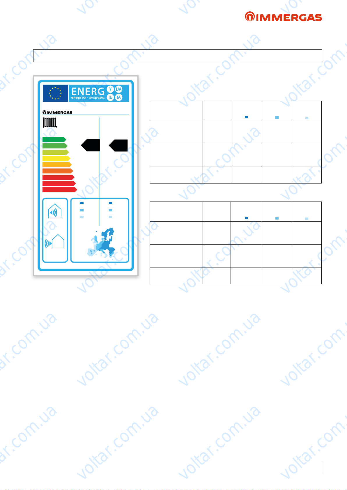
voltar.com.ua
voltar.com.ua
AUDAX TOP 12 ErP
19 PRODUCT FICHE REGULATION 811/2013
AUDAX TOP 12 ErP
Low temperature (30/35)
voltar.com.ua
AUDAX TOP 12 ErP
Parameter Value
voltar.com.ua
Colder
zones
Average
zones
voltar.com.ua
Hotter
voltar.com.ua
zones
A
A
A
B
C
D
E
F
G
67
55 °C 35 °C
++
+
dB
dB
+
A
voltar.com.ua
13.67
8.68 10.00
8.04
kW kW
A
15.75
9.20
+
Annual energy
consumption for the
heating function (Q
Room central heating
seasonal eciency (η
Nominal heat output kW 15.75 10.00 9.20
Average temperature (47/55)
Parameter Value
Annual energy
consumption for the
heating function (QHE)
Room central heating
seasonal eciency (η
Nominal heat output kW 13.67 8.68 8.04
voltar.com.ua
kWh/year 12620 6467 2809
)
HE
ηs % 115 125 171
)
s
Colder
zones
kWh/year 11859 6077 2651
ηs % 106 115 158
)
s
Average
zones
voltar.com.ua
Hotter
zones
voltar.com.ua
voltar.com.ua
voltar.com.ua
voltar.com.ua
voltar.com.ua
voltar.com.ua
voltar.com.ua
voltar.com.ua
41
voltar.com.ua
Page 42
voltar.com.ua
voltar.com.ua
AUDAX TOP 12 ErP
20 AUDAX TOP 12 ErP ''POWER'' AND ''COP'' CENTRAL HEATING
• TOL = -20 °C
voltar.com.ua
Air
temp. °C
d.b. (w.b.) Water ow temperature 35 °C
20 (19) 16.32 4.94 18.45 5.63 5.72 5.58
10 (9) 12.92 3.91 14.61 4.30 4.37 4.26
7 (6) 11.86 3.61 15.45 3.95 3.96 3.86
2 (1) 8.75 2.87 10.11 3.11 3.16 3.08
0 (-1) 8.50 2.57 9.61 3.00 3.05 2.97
-3 (-4) 7.83 2.37 8.85 2.85 2.90 2.83
-7 (-8) 6.94 2.10 7.40 2.52 2.56 2.50
-15 (-16) 6.44 1.95 7.28 2.28 2.31 2.26
-20 (-21) 3.22 1.50 3.22 2.08 2.10 2.08
d.b. (w.b.) Water ow temperature 45 °C
20 (19) 15.18 4.60 17.16 3.80 3.86 3.77
10 (9) 12.31 3.73 15.92 3.21 3.26 3.18
7 (6) 12.91 3.47 12.95 3.03 3.08 3.01
2 (1) 8.48 2.74 9.59 2.61 2.67 2.57
0 (-1) 8.06 2.44 9.12 2.42 2.46 2.40
-3 (-4) 7.43 2.25 8.40 2.31 2.34 2.29
-7 (-8) 6.63 2.01 7.50 2.19 2.23 2.17
-15 (-16) 6.04 1.83 6.82 2.10 2.14 2.08
-20 (-21) 3.02 1.23 3.02 1.96 2.00 1.96
Output (kW)
Nom
Output (kW)
Min
Output (kW)
Max
voltar.com.ua
voltar.com.ua
COP (EN 14511)
Nom
COP (EN 14511)
Min
COP (EN 14511)
Max
voltar.com.ua
voltar.com.ua
voltar.com.ua
voltar.com.ua
d.b. (w.b.) Water ow temperature 55 °C
20 (19) 15.85 4.42 14.60 3.08 3.15 3.08
10 (9) 11.46 3.61 12.35 2.63 2.68 2.63
7 (6) 10.27 3.36 11.50 2.50 2.54 2.48
2 (1) 8.66 2.71 9.61 2.20 2.23 2.18
0 (-1) 8.23 2.45 9.13 2.08 2.11 2.06
-3 (-4) 7.44 2.25 8.41 1.98 2.01 1.96
-7 (-8) 6.37 1.93 7.20 1.80 1.83 1.78
-15 (-16) 2.87 1.69 2.87 1.67 1.69 1.67
-20 (-21) 1.13 1.13 1.13 1.53 1.53 1.53
d.b. (w.b.) Water ow temperature 60 °C
20 (19) 11.10 3.95 11.60 2.56 2.60 2.56
10 (9) 10.84 3.28 11.25 2.20 2.23 2.20
7 (6) 10.19 3.09 11.00 2.09 2.12 2.08
2 (1) 7.89 2.50 8.92 1.85 1.88 1.83
0 (-1) 7.49 2.27 8.47 1.75 1.78 1.74
-3 (-4) 6.91 2.09 7.81 1.67 1.70 1.66
-7 (-8) 6.12 1.85 6.92 1.56 1.59 1.55
-15 (-16) 1.48 1.48 1.48 1.49 1.49 1.49
-20 (-21) 1.10 1.10 1.10 1.35 1.35 1.35
voltar.com.ua
voltar.com.ua
voltar.com.ua
voltar.com.ua
voltar.com.ua
voltar.com.ua
42
voltar.com.ua
voltar.com.ua
voltar.com.ua
Page 43
voltar.com.ua
voltar.com.ua
AUDAX TOP 12 ErP
20.1 AUDAX TOP 12 ErP ''POWER'' AND ''EER'' IN COOLING
voltar.com.ua
Air
temp. °C
d.b. Water ow temperature 18 °C
45 10.34 4.99 12.35 2.76 3.40 2.45
35 13.54 5.88 16.12 3.66 4.95 3.21
25 15.12 6.61 18.12 4.94 7.43 4.04
15 16.62 7.26 19.92 6.89 12.23 5.12
5 7.86 7.86 7.86 17.04 17.04 17.04
d.b. Water ow temperature 15 °C
45 9.89 4.52 11.69 2.59 3.15 2.32
35 12.60 5.32 14.91 3.42 4.53 3.06
25 15.52 6.57 18.41 6.44 10.75 4.98
15 15.52 6.57 18.41 6.44 10.75 4.98
5 7.11 7.11 7.11 15.1 15.1 15.1
d.b. Water ow temperature 10 °C
45 9.14 3.73 10.59 2.31 2.73 2.11
35 11.10 4.39 12.88 3.10 3.85 2.81
25 12.46 4.94 14.48 4.17 5.48 3.65
Output (kW)
Nom
Output (kW)
Min
voltar.com.ua
voltar.com.ua
Output (kW)
Max
EER (EN 14511)
Nom
EER (EN 14511)
Min
EER (EN 14511)
Max
voltar.com.ua
voltar.com.ua
voltar.com.ua
voltar.com.ua
15 13.67 5.41 15.89 5.69 8.29 4.73
5 12.05 5.86 13.47 10.21 11.87 9.51
d.b. Water ow temperature 7 °C
45 8.68 3.26 9.93 2.14 2.48 1.98
35 10.24 3.83 11.67 2.96 3.43 2.66
25 11.47 4.31 13.12 3.88 4.74 3.51
15 12.57 4.72 14.37 5.24 6.81 4.59
5 13.62 5.12 15.57 7.64 9.94 6.69
d.b. Water ow temperature 5 °C
45 8.38 2.95 9.49 2.02 2.31 1.89
35 9.60 3.46 10.85 2.78 3.16 2.56
25 10.81 3.89 12.21 3.69 4.25 3.41
15 11.83 4.26 13.36 4.94 5.82 4.49
5 14.66 4.62 16.97 5.94 8.65 4.81
voltar.com.ua
voltar.com.ua
voltar.com.ua
voltar.com.ua
voltar.com.ua
voltar.com.ua
voltar.com.ua
voltar.com.ua
43
voltar.com.ua
Page 44
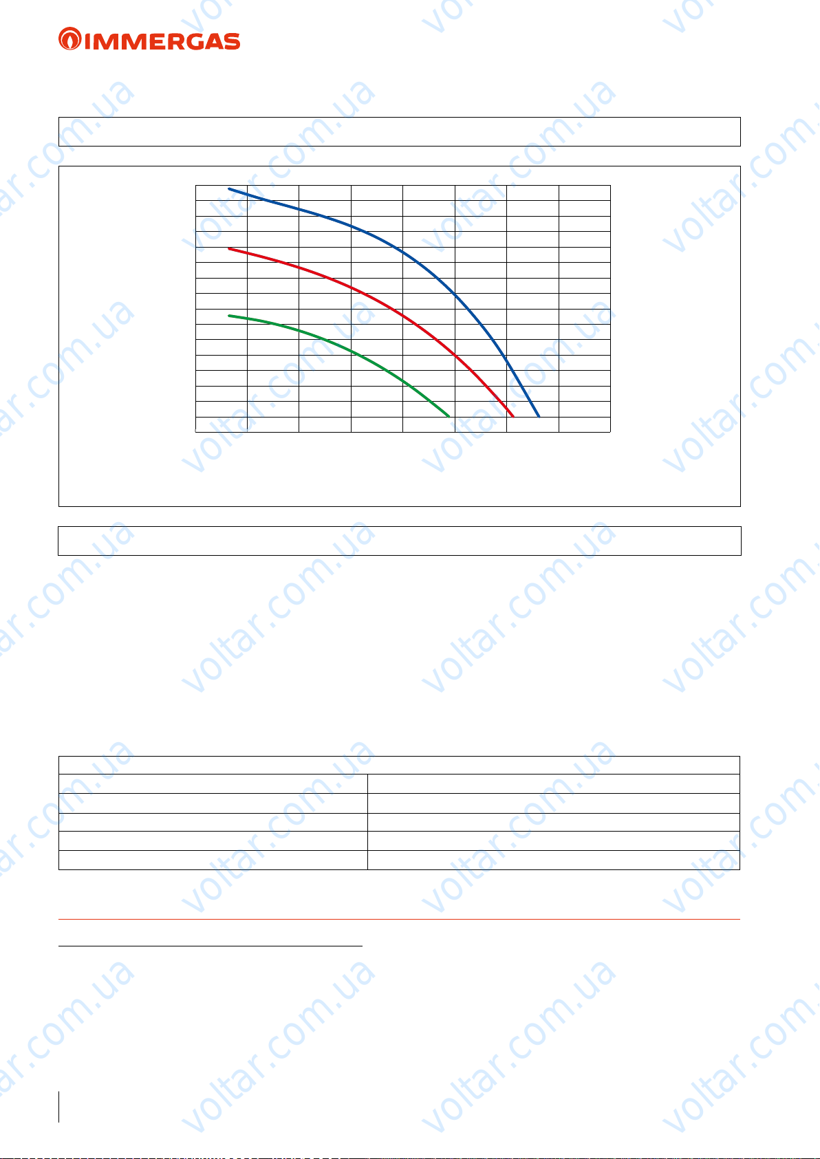
voltar.com.ua
voltar.com.ua
AUDAX TOP 12 ErP
21 GRAPH OF AUDAX TOP 12 ErP PUMP FLOW RATE/HEAD
95
90
85
80
75
voltar.com.ua
70
65
60
55
50
45
40
Head (kPa)
35
30
25
20
15
0 500 1000 1500 2000 2500 3000 3500 4000
voltar.com.ua
All curves have been dened in constant pressure mode with minimum, intermediate and maximum speed.
Flow rate l/h
voltar.com.ua
voltar.com.ua
voltar.com.ua
voltar.com.ua
voltar.com.ua
21.1 AUDAX TOP 12 ErP PUMP SETTINGS AND CONFIGURATIONS
AUDAX TOP 12 ErP range boilers are supplied with a low power
consumption pump with variable speed control.
e pump's interface enables you to select between 6 pressure
levels with 2 types of controls:
• 3 constant pressure (CP) curves
• 3 proportional pressure (PP) curves
Constant Pressure Curve (CP) default setting. e circulator
pump maintains the pressure level (head) constant as the system
heat demand decreases (ow rate reduction). With these settings,
the pump is suitable for all oor systems.
Setting procedure:
1) Factory setting Constant Pressure Curve CP3
2) Press the button for 10 seconds e pump goes into setting mode - the LED starts ashing
3) Each time it is pressed, the settings change LED “I”, “II”, and “III” are lit / the control curve and mode change
4) 10 seconds after the button is not pressed e setting is changed - the pump goes back to operating mode
5) LED “I” or “II” or “III” is still lit e pump is operating with the selected mode and curve.
voltar.com.ua
voltar.com.ua
Proportional Pressure Curve (PP) is allows the pressure level
(head) to be proportionally reduced as the system heat demand
decreases (ow rate reduction). anks to this function, the
electric power consumption of the circulator pump is reduced
further: the energy (power) used by the pump decreases according
to the pressure level and ow rate. With this setting, the pump
guarantees optimal performance in most heating systems, proving particularly suitable in single-pipe and two-pipe installations.
voltar.com.ua
voltar.com.ua
voltar.com.ua
voltar.com.ua
TECHNICAL NOTE: System minimum water content:
To facilitate proper execution of the AUDAX TOP ErP heat pump defrost cycles, a minimum water content in the system is required,
which must be: 6 l/kW of the machine's power for any type of system. e ywheel guarantees normal operation of AUDAX TOP ErP
with systems divided into zones (with variable water content in circulation). e ywheel also guarantees proper operation with fan coils
used for cooling (a condition in which the ow temperature is very low and has signicant heat load variations that vary the number of
active fan coils). It is also important to check that the dehumidier line has a minimum of 3 l/kW of the machine (dehumidier hydraulic
circuit connection).
N.B.: for inertial tanks codes supplied by Immergas, refer to page 107.
44
voltar.com.ua
voltar.com.ua
voltar.com.ua
Page 45
voltar.com.ua
voltar.com.ua
AUDAX TOP 16 ErP
22 AUDAX TOP 16 ErP TECHNICAL DATA
Central heating circuit
Power in CH mode with water set at 35 °C
Power in CH mode with water set at 45 °C
Power in CH mode with water set at 55 °C
CH mode COP with water set at 35 °C
CH mode COP with water set at 45 °C
CH mode COP with water set at 55 °C
Min/max heat power with water set at 35 °C
Min/max heat power with water set at 45 °C
Min/max heat power with water set at 55 °C
Flow temperature range °C 20 / 60
Outdoor temperature heating operation limits °C - 20 / 30
voltar.com.ua
(1)
kW 15.00
(2)
kW 14.50
(3)
kW 12.17
(1)
4.20
(2)
3.30
(3)
2.98
(1)
kW 3.44 / 17.41
(2)
kW 3.07 / 16.52
(3)
kW 2.78 / 15.26
voltar.com.ua
voltar.com.ua
voltar.com.ua
Cooling circuit
Power in cooling mode with water set at 18 °C
Power in cooling mode with water set at 7 °C
Cooling mode EER with water set at 18 °C
Cooling mode EER with water set at 7 °C
Min/max cooling capacity with water set at 18 °C
Min/max cooling capacity with water set at 7 °C
Flow temperature range°C 4 / 18
Outdoor temperature Cooling operation limits °C 0 / 46
General data
Max system operating pressure bar 3
Head available on the system with 2500 l/h flow rate kPa (m H2O) 60 (6.12)
Expansion vessel capacity l 3
Water circuit content l 2.5
C.H. sound power level dB(A) 68
Appliance electric protection rating IP X4
Electric supply voltage V - Hz 400 - 50
Permitted voltage range V 376 - 424
Maximum absorbed power W 6500
Maximum absorbed current A 11.1
Fuse inserted A 16 - Type B
Refrigerant fluid load (R410A)* g 3385
Heat Pump weight kg 116
voltar.com.ua
voltar.com.ua
voltar.com.ua
(1)
kW 16.00
(2)
kW 13.00
(1)
(2)
(1)
(2)
voltar.com.ua
kW 5.72 / 17.31
kW 3.75 / 13.55
voltar.com.ua
voltar.com.ua
voltar.com.ua
3.81
2.91
voltar.com.ua
voltar.com.ua
* Hermetically sealed system.
THE REPORTED DATA REFERS TO THE FOLLOWING CONDITIONS (in compliance with EN 14511)
ROOM C.H. MODE (°C) COOLING MODE (°C)
Room Antifreeze WATER (F/R)
Room Antifreeze WATER (F/R)
Room Antifreeze WATER (F/R)
voltar.com.ua
(1)
- AIR (db/wb) 35/30 - 7/6 18/23 - 35 (db)
(2)
- AIR (db/wb) 45/40 - 7/6 7/12 - 35 (db)
(3)
- AIR (db/wb) 55/47 - 7/6
voltar.com.ua
:
45
voltar.com.ua
Page 46
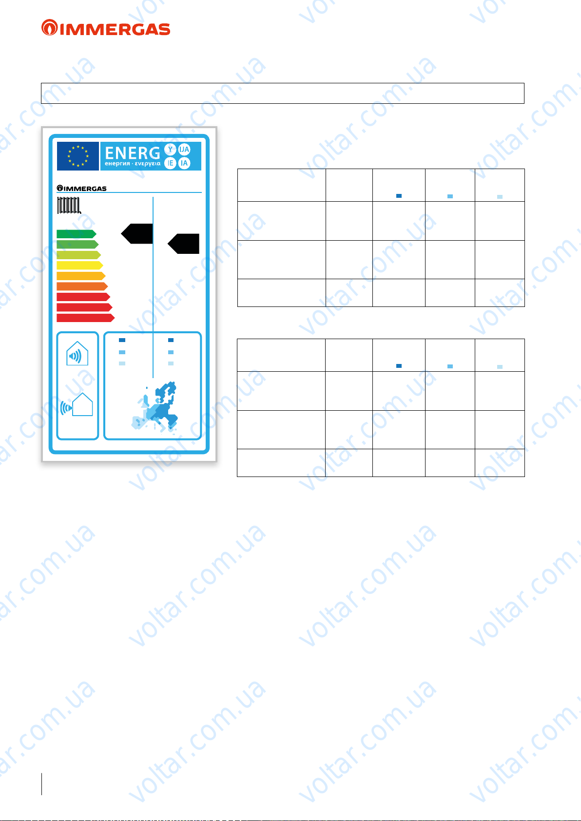
voltar.com.ua
voltar.com.ua
AUDAX TOP 16 ErP
23 PRODUCT FICHE REGULATION 811/2013
AUDAX TOP 16 ErP
Low temperature (30/35)
voltar.com.ua
AUDAX TOP 16 ErP
Parameter Value
voltar.com.ua
Colder
zones
Average
zones
voltar.com.ua
Hotter
voltar.com.ua
zones
A
A
A
B
C
D
E
F
G
68
55 °C 35 °C
++
+
dB
dB
++
A
voltar.com.ua
15.05
9.37 11.12
8.67
kW kW
A
17.86
10.29
+
Annual energy
consumption for the
heating function (QHE)
Room central heating
seasonal eciency (η
Nominal heat output kW 17.86 11.12 10.29
Average temperature (47/55)
Parameter Value
Annual energy
consumption for the
heating function (QHE)
Room central heating
seasonal eciency (η
Nominal heat output kW 15.05 9.37 8.67
kWh/year 12237 6230 2714
ηs % 135 144 198
)
s
voltar.com.ua
Colder
zones
kWh/year 11404 5806 2537
ηs % 122 130 179
)
s
Average
zones
voltar.com.ua
Hotter
zones
voltar.com.ua
voltar.com.ua
voltar.com.ua
voltar.com.ua
voltar.com.ua
voltar.com.ua
46
voltar.com.ua
voltar.com.ua
voltar.com.ua
Page 47
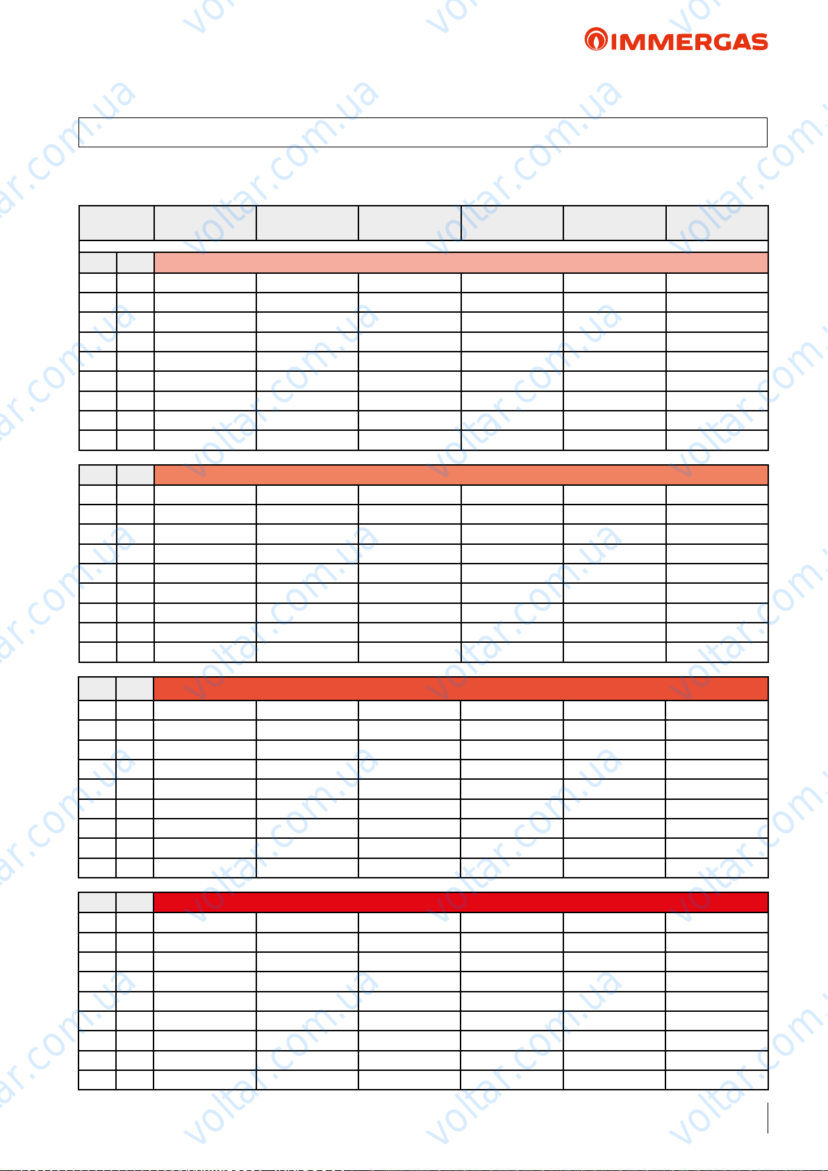
voltar.com.ua
voltar.com.ua
AUDAX TOP 16 ErP
24 AUDAX TOP 16 ErP ''POWER'' AND ''COP'' CENTRAL HEATING
• TOL = -20 °C
voltar.com.ua
Air
temp. °C
d.b. (w.b.) Water ow temperature 35 °C
20 (19) 20.24 4.72 23.49 5.89 6.14 5.86
10 (9) 16.15 3.73 18.73 4.57 4.69 4.55
7 (6) 15.00 3.44 17.41 4.20 4.25 4.18
2 (1) 9.50 2.65 12.55 3.10 3.24 3.07
0 (-1) 8.69 2.30 11.15 2.77 3.08 2.70
-3 (-4) 8.49 2.13 10.54 2.75 2.94 2.69
-7 (-8) 8.00 1.90 9.46 2.60 2.62 2.40
-15 (-16) 7.42 1.76 8.35 2.45 2.47 2.45
-20 (-21) 4.45 1.36 4.45 1.78 1.88 1.78
d.b. (w.b.) Water ow temperature 45 °C
20 (19) 18.92 4.07 21.55 4.03 4.14 3.92
10 (9) 15.90 3.30 18.11 3.40 3.49 3.31
7 (6) 14.50 3.07 16.52 3.30 3.29 3.21
2 (1) 9.30 2.47 11.88 2.65 2.71 2.51
0 (-1) 8.61 2.13 11.04 2.49 2.51 2.37
-3 (-4) 8.40 1.97 10.48 2.39 2.40 2.27
-7 (-8) 8.00 1.76 9.44 2.26 2.26 2.13
-15 (-16) 7.05 1.62 8.03 1.80 2.14 1.80
-20 (-21) 3.00 1.38 3.00 1.70 1.73 1.70
Output (kW)
Nom
Output (kW)
Min
voltar.com.ua
voltar.com.ua
Output (kW)
Max
COP (EN 14511)
Nom
COP (EN 14511)
Min
COP (EN 14511)
Max
voltar.com.ua
voltar.com.ua
voltar.com.ua
voltar.com.ua
d.b. (w.b.) Water ow temperature 55 °C
20 (19) 15.68 3.66 20.02 3.58 3.61 3.33
10 (9) 15.07 2.98 16.81 3.02 3.04 2.80
7 (6) 12.00 2.78 15.26 2.85 2.87 2.65
2 (1) 7.96 2.30 10.18 2.24 2.25 2.08
0 (-1) 7.56 2.02 8.95 2.11 2.13 1.97
-3 (-4) 6.90 1.86 8.71 2.01 2.03 1.88
-7 (-8) 6.49 1.65 7.94 1.88 1.90 1.76
-15 (-16) 3.00 1.59 3.00 1.78 1.80 1.78
-20 (-21) 1.27 1.27 1.27 1.69 1.69 1.69
d.b. (w.b.) Water ow temperature 60 °C
20 (19) 16.03 3.12 19.02 3.29 3.39 3.21
10 (9) 15.69 2.59 15.97 2.75 2.84 2.69
7 (6) 12.80 2.52 14.5 2.60 2.68 2.54
2 (1) 8.53 2.10 9.67 1.98 2.04 1.93
0 (-1) 7.50 1.85 8.50 1.56 1.61 1.53
-3 (-4) 7.30 1.71 8.27 1.52 1.57 1.46
-7 (-8) 6.66 1.51 7.54 1.51 1.55 1.42
-15 (-16) 1.49 1.49 1.49 1.48 1.48 1.48
-20 (-21) 1.22 1.12 1.22 1.34 1.34 1.34
voltar.com.ua
voltar.com.ua
voltar.com.ua
voltar.com.ua
voltar.com.ua
voltar.com.ua
voltar.com.ua
voltar.com.ua
47
voltar.com.ua
Page 48
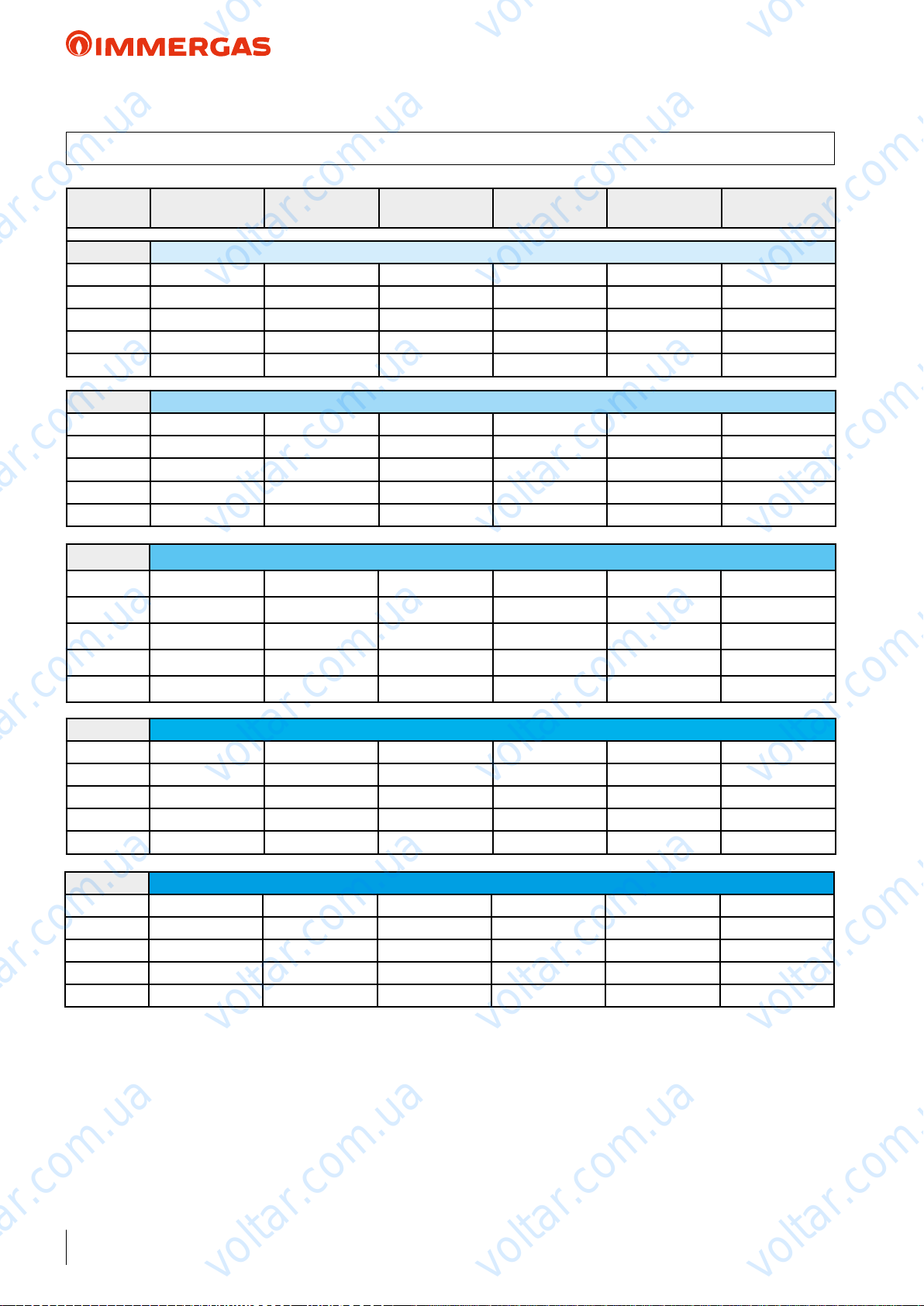
voltar.com.ua
voltar.com.ua
AUDAX TOP 16 ErP
24.1 AUDAX TOP 16 ErP ''POWER'' AND ''EER'' IN COOLING
voltar.com.ua
Air
temp. °C
d.b. Water ow temperature 18 °C
45 13.03 4.85 13.57 2.86 3.94 2.86
35 16.00 5.72 17.31 3.81 5.75 3.60
25 17.98 6.43 20.16 5.33 8.67 4.62
15 19.77 7.07 22.16 7.31 14.41 5.86
5 7.65 7.65 7.65 20.06 20.06 20.06
d.b. Water ow temperature 15 °C
45 12.16 4.40 12.62 2.70 3.59 2.70
35 15.18 5.18 16.28 3.56 5.18 3.39
25 17.06 5.83 18.82 4.93 7.69 4.38
15 18.75 6.40 20.67 6.70 12.47 5.59
5 6.93 6.93 6.93 17.50 17.50 17.50
d.b. Water ow temperature 10 °C
45 10.70 3.65 11.04 2.45 3.00 2.43
35 13.82 4.29 14.58 3.16 4.23 3.04
25 15.54 4.82 16.58 4.25 6.05 3.97
Output (kW)
Nom
voltar.com.ua
voltar.com.ua
Output (kW)
Min
Output (kW)
Max
EER (EN 14511)
Nom
EER (EN 14511)
Min
EER (EN 14511)
Max
voltar.com.ua
voltar.com.ua
voltar.com.ua
voltar.com.ua
15 17.04 5.29 18.18 5.69 9.24 5.14
5 14.72 5.73 15.25 10.87 13.22 10.64
d.b. Water ow temperature 7 °C
45 9.82 3.20 10.09 2.30 2.64 2.27
35 13.00 3.75 13.55 2.91 3.67 2.83
25 14.62 4.22 15.24 3.85 5.07 3.72
15 16.01 4.62 16.69 5.09 7.30 4.87
5 17.37 5.02 18.11 7.43 10.65 7.10
d.b. Water ow temperature 5 °C
45 9.24 2.90 9.45 2.20 2.41 2.16
35 12.45 3.40 12.87 2.75 3.29 2.68
25
15 15.33 4.18 15.70 4.69 6.01 4.69
5 19.14 4.54 20.01 5.13 8.94 4.75
voltar.com.ua
14.01 3.82 14.34 3.58 4.42 3.56
voltar.com.ua
voltar.com.ua
voltar.com.ua
voltar.com.ua
voltar.com.ua
48
voltar.com.ua
voltar.com.ua
voltar.com.ua
Page 49
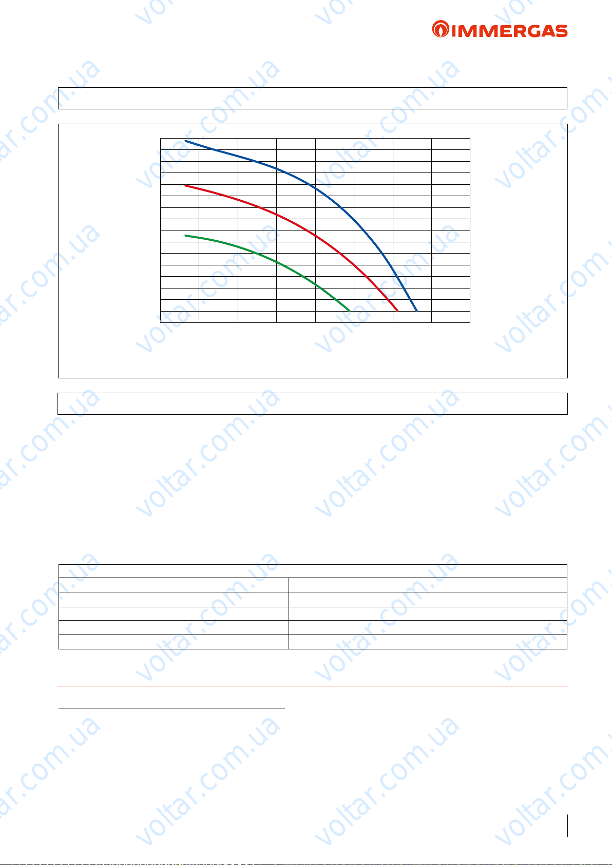
voltar.com.ua
voltar.com.ua
AUDAX TOP 16 ErP
25 GRAPH OF AUDAX TOP 16 ErP PUMP FLOW RATE/HEAD
95
90
85
80
75
voltar.com.ua
70
65
60
55
50
45
40
Head (kPa)
35
30
25
20
15
0 500 1000 1500 2000 2500 3000 3500 4000
voltar.com.ua
All curves have been dened in constant pressure mode with minimum, intermediate and maximum speed.
Flow rate l/h
voltar.com.ua
voltar.com.ua
voltar.com.ua
voltar.com.ua
voltar.com.ua
25.1 AUDAX TOP 16 ErP PUMP SETTINGS AND CONFIGURATIONS
AUDAX TOP 16 ErP range boilers are supplied with a low power
consumption pump with variable speed control.
e pump's interface enables you to select between 6 pressure
levels with 2 types of controls:
• 3 constant pressure (CP) curves
• 3 proportional pressure (PP) curves
Constant Pressure Curve (CP) default setting. e circulator
pump maintains the pressure level (head) constant as the system
heat demand decreases (ow rate reduction). With these settings,
the pump is suitable for all oor systems.
Setting procedure:
1) Factory setting Constant Pressure Curve CP3
2) Press the button for 10 seconds e pump goes into setting mode - the LED starts ashing
3) Each time it is pressed, the settings change LED “I”, “II”, and “III” are lit / the control curve and mode change
4) 10 seconds after the button is not pressed e setting is changed - the pump goes back to operating mode
5) LED “I” or “II” or “III” is still lit e pump is operating with the selected mode and curve.
voltar.com.ua
voltar.com.ua
Proportional Pressure Curve (PP) is allows the pressure level
(head) to be proportionally reduced as the system heat demand
decreases (ow rate reduction). anks to this function, the
electric power consumption of the circulator pump is reduced
further: the energy (power) used by the pump decreases according
to the pressure level and ow rate. With this setting, the pump
guarantees optimal performance in most heating systems, proving particularly suitable in single-pipe and two-pipe installations.
voltar.com.ua
voltar.com.ua
voltar.com.ua
voltar.com.ua
TECHNICAL NOTE: System minimum water content:
To facilitate proper execution of the AUDAX TOP ErP heat pump defrost cycles, a minimum water content in the system is required,
which must be: 6 l/kW of the machine's power for any type of system. e ywheel guarantees normal operation of AUDAX TOP ErP
with systems divided into zones (with variable water content in circulation). e ywheel also guarantees proper operation with fan coils
used for cooling (a condition in which the ow temperature is very low and has signicant heat load variations that vary the number of
active fan coils). It is also important to check that the dehumidier line has a minimum of 3 l/kW of the machine (dehumidier hydraulic
circuit connection).
N.B.: for inertial tanks codes supplied by Immergas, refer to page 107.
49
voltar.com.ua
voltar.com.ua
voltar.com.ua
Page 50
voltar.com.ua
voltar.com.ua
AUDAX TOP 18 ErP
26 AUDAX TOP 18 ErP TECHNICAL DATA
Central heating circuit
Power in CH mode with water set at 35 °C
Power in CH mode with water set at 45 °C
Power in CH mode with water set at 55 °C
CH mode COP with water set at 35 °C
CH mode COP with water set at 45 °C
CH mode COP with water set at 55 °C
Min/max heat power with water set at 35 °C
Min/max heat power with water set at 45 °C
Min/max heat power with water set at 55 °C
Flow temperature range °C 20 / 60
Outdoor temp. limits for Heating mode operation °C - 20 / 30
voltar.com.ua
(1)
kW 17,14
(2)
kW 16,16
(3)
kW 15,27
(1)
4.10
(2)
3.40
(3)
2,69
(1)
kW 3,35 / 24,65
(2)
kW 3,20 / 23,15
(3)
kW 3,01 / 18,10
voltar.com.ua
voltar.com.ua
voltar.com.ua
Cooling circuit
Power in cooling mode with water set at 18 °C
Power in cooling mode with water set at 7 °C
Cooling mode EER with water set at 18 °C
Cooling mode EER with water set at 7 °C
Min/max cooling capacity with water set at 18 °C
Min/max cooling capacity with water set at 7 °C
Flow temperature range °C 5 / 18
Outdoor temp. limits for Cooling mode operation °C 0 / 46
General data
System max. working pressure bar 3
Head available on the system with 2700 l/h flow rate kPa (m c.a.) 84 (8,56)
Expansion vessel capacity l 8
C.H. sound power level dB(A) 71
Appliance electric protection rating IP X4
Electric power supply V - Hz 400 - 50
Permitted voltage range V 360 - 440
Maximum power absorbed W 10800
Maximum current absorbed A 16,7
Fuse inserted A 25 - Type C
Refrigerant fluid load (R410A)* g 8000
Heat pump Weight kg 190,9
voltar.com.ua
(1)
kW 19,38
(2)
kW 14,88
(1)
3.87
(2)
3.00
(1)
kW 4,52 / 21,17
(2)
kW 3,13 / 15,45
voltar.com.ua
voltar.com.ua
voltar.com.ua
voltar.com.ua
voltar.com.ua
voltar.com.ua
voltar.com.ua
voltar.com.ua
* Hermetically sealed system.
THE REPORTED DATA REFERS TO THE FOLLOWING CONDITIONS (in compliance with EN 14511)
ROOM HEATING PHASE (°C) COOLING PHASE (°C)
Water TEMP. (F/R)
Water TEMP. (F/R)
Water TEMP. (F/R)
50
(1)
- AIR (db/wb) 35/30 - 7/6 18/23 - 35 (bs)
(2)
- AIR (db/wb) 45/40 - 7/6 7/12 - 35 (bs)
(3)
- AIR (db/wb) 55/47 - 7/6
voltar.com.ua
voltar.com.ua
:
voltar.com.ua
Page 51
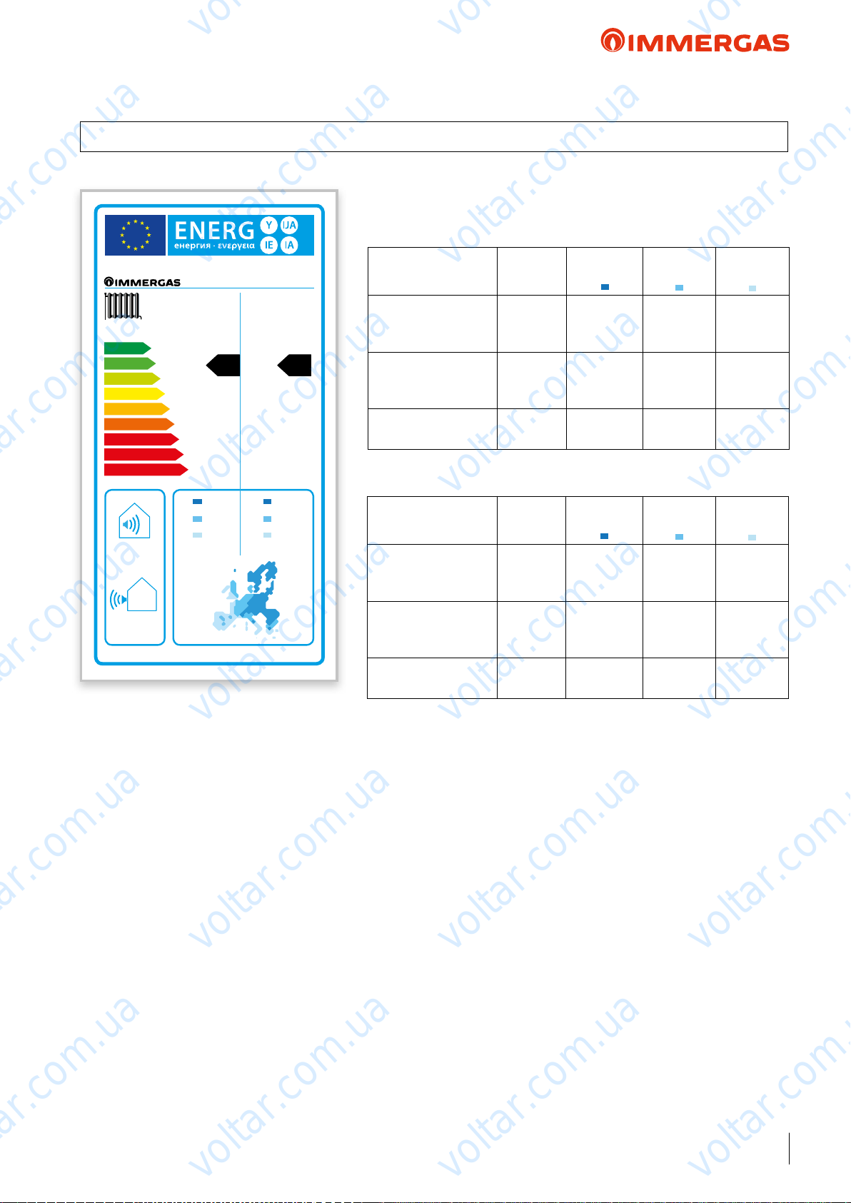
voltar.com.ua
voltar.com.ua
AUDAX TOP 18 ErP
27 PRODUCT FICHE REGULATION 811/2013
AUDAX TOP 18 ErP
Low temperature (30/35)
voltar.com.ua
AUDAX TOP 18 ErP
Parameter Value
voltar.com.ua
Colder
zones
Average
zones
voltar.com.ua
Hotter
voltar.com.ua
zones
++
A
A
+
A
B
A
C
B
D
C
D
E
E
F
F
G
G
71dBdB
55 °C 35 °C
+
A
voltar.com.ua
16,41 13,65
9,11 9,25
12,5 14,67
kW kW
+
A
Annual energy consumption for the central
heating function (QHE)
Room central heating
seasonal eciency (η
Nominal heat output kW 13,65 9,25 14,67
Average temperature (47/55)
Annual energy consumption for the central
heating function (QHE)
Room central heating
seasonal eciency (η
Nominal heat output kW 16,41 9,11 12,50
kWh/year 10390 5169 3425
ηs % 121 144 225
)
s
voltar.com.ua
Parameter Value
kWh/year 13894 6260 4383
ηs % 108 118 149
)
s
Colder
zones
Average
zones
voltar.com.ua
Hotter
zones
voltar.com.ua
voltar.com.ua
voltar.com.ua
voltar.com.ua
voltar.com.ua
voltar.com.ua
voltar.com.ua
voltar.com.ua
51
voltar.com.ua
Page 52
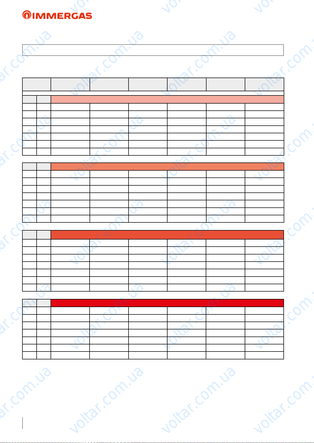
voltar.com.ua
voltar.com.ua
AUDAX TOP 18 ErP
28 AUDAX TOP 18 ErP ''POWER'' AND ''COP'' CENTRAL HEATING
• TOL = -20 °C
voltar.com.ua
Room Antifreeze air °C
d.b. (w.b.) Water ow temperature 35 °C
10 (9) 17.27 3.73 24.83 4.13 5.50 3.47
7 (6) 17.14 3.35 24.65 4.10 3.93 3.53
2 (1) 12.72 5.50 18.04 3.05 3.22 2.53
-7 (-8) 5.86 3.44 8.46 2.41 2.26 2.11
-10 (-11) 5.40 3.46 5.51 2.28 2.11 2.25
-15 (-16) 4.14 3.01 4.15 2.11 1.91 2.09
-20 (-21) 3.52 2.51 3.58 1.89 1.70 1.89
d.b. (w.b.) Water ow temperature 45 °C
10 (9) 16.25 3.54 24.49 3.33 3.69 2.89
7 (6) 16.16 3.20 23.15 3.40 2.73 2.88
2 (1) 12.03 5.17 17.31 2.50 3.02 2.09
-7 (-8) 7.47 3.27 10.92 2.19 1.83 1.92
-10 (-11) 6.94 4.42 7.14 2.10 1.73 2.08
-15 (-16) 5.29 3.80 5.33 1.92 1.57 1.92
-20 (-21) 4.57 3.29 4.61 1.76 1.44 1.76
Output (kW)
Nom.
voltar.com.ua
voltar.com.ua
Output (kW)
Min.
Output (kW)
Max.
COP (EN 14511)
Nom.
COP (EN 14511)
Min.
COP (EN 14511)
Max.
voltar.com.ua
voltar.com.ua
voltar.com.ua
voltar.com.ua
d.b. (w.b.) Water ow temperature 55 °C
10 (9) 15.35 3.34 18.64 2.75 2.75 2.75
7 (6) 15.27 3.01 18.10 2.69 2.07 2.68
2 (1) 11.43 4.94 13.20 2.10 2.41 1.95
-7 (-8) 7.15 3.10 8.45 1.87 1.52 1.79
-10 (-11) 6.62 4.15 6.80 1.78 1.43 1.77
-15 (-16) -- -- -- -- -- --
-20 (-21) -- -- -- -- -- --
d.b. (w.b.) Water ow temperature 60 °C
10 (9) 14.69 3.32 15.66 2.49 2.48 2.44
7 (6) 14.74 2.77 15.30 2.58 1.71 2.57
2 (1) 11.07 4.78 11.37 1.92 2.17 1.90
-7 (-8) 6.95 3.07 7.06 1.72 1.41 1.69
-10 (-11) 6.45 4.18 6.58 1.65 1.36 1.63
-15 (-16) -- -- -- -- -- --
-20 (-21) -- -- -- -- -- --
voltar.com.ua
voltar.com.ua
voltar.com.ua
voltar.com.ua
voltar.com.ua
voltar.com.ua
52
voltar.com.ua
voltar.com.ua
voltar.com.ua
Page 53
voltar.com.ua
voltar.com.ua
AUDAX TOP 18 ErP
28.1 AUDAX TOP 18 ErP ''POWER'' AND ''EER'' CENTRAL HEATING
voltar.com.ua
Room Antifreeze air °C
d.b. Water ow temperature 18 °C
45 18.10 5.79 18.13 2.99 1.95 2.99
35 19.83 4.52 21.17 3.87 3.67 3.65
25 21.04 6.84 21.46 4.94 7.45 4.93
15 21.54 6.94 21.55 5.26 8.88 5.26
10 21.68 8.92 21.69 5.98 7.50 5.98
d.b. Water ow temperature 15 °C
45 16.30 5.30 16.33 2.75 1.80 2.75
35 18.82 4.11 19.51 3.51 3.23 3.39
25 19.37 6.00 19.37 4.66 5.19 4.66
15 19.94 6.81 19.94 5.05 8.84 5.05
10 20.13 8.29 20.13 5.79 7.30 5.79
d.b. Water ow temperature 10 °C
45 14.03 4.55 14.05 2.50 1.57 2.50
35 16.26 3.48 16.88 3.20 2.64 3.10
25 16.74 5.14 16.74 4.20 4.34 4.20
Output (kW)
Nom.
Output (kW)
Min.
voltar.com.ua
voltar.com.ua
Output (kW)
Max.
EER (EN 14511)
Nom.
EER (EN 14511)
Min.
EER (EN 14511)
Max.
voltar.com.ua
voltar.com.ua
voltar.com.ua
voltar.com.ua
15 17.39 6.06 17.39 4.67 8.92 4.66
10 17.63 7.77 17.63 5.44 7.20 5.44
d.b. Water ow temperature 7 °C
45 12.80 4.14 12.82 2.35 1.45 2.35
35 14.88 3.13 15.45 3.00 2.36 2.93
25 15.31 9.40 15.31 3.93 4.47 3.93
15 15.97 10.31 15.98 4.43 6.07 4.43
10 16.25 13.84 16.25 5.20 4.98 5.20
d.b. Water ow temperature 5 °C
45 11.99 3.87 12.01 2.25 1.38 2.25
35 13.97 2.91 14.52 2.89 2.19 2.82
25
15 15.06 9.65 15.06 4.26 5.48 4.26
10 15.34 13.05 15.34 5.04 4.72 5.04
voltar.com.ua
14.16 8.78 14.16 3.67 4.18 3.67
voltar.com.ua
voltar.com.ua
voltar.com.ua
voltar.com.ua
voltar.com.ua
voltar.com.ua
voltar.com.ua
53
voltar.com.ua
Page 54
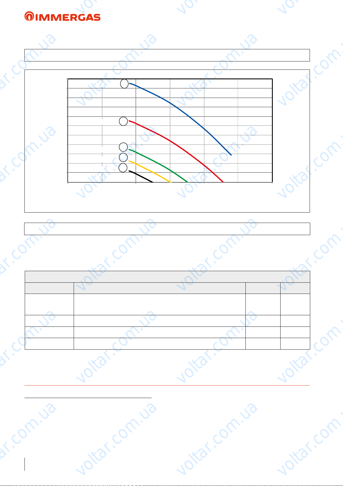
voltar.com.ua
voltar.com.ua
AUDAX TOP 18 ErP
29 GRAPH OF AUDAX TOP 18 ErP PUMP FLOW RATE/HEAD
voltar.com.ua
110
100
90
80
70
60
50
Head (kPa)
40
30
20
10
0
0 1800 5400
All curves have been dened in constant pressure mode with various speeds.
29.1 AUDAX TOP 18 ErP PUMP SETTINGS AND CONFIGURATIONS
AUDAX TOP 18 ErP range boilers are supplied with a low power
consumption pump with variable speed control and settable
according to the following settings.
Speed 100%
1
voltar.com.ua
Speed 75%
Speed 50%
Speed 38%
Speed 25%
voltar.com.ua
2
3
4
5
Flow rate l/h
voltar.com.ua
3600900 45002700
voltar.com.ua
voltar.com.ua
voltar.com.ua
Assistance Menu -> System denition
Menu item Description Range Default
Pump control
Minimum speed Value of minimum speed used in modulating operation. 19% ÷ 50% 50%
Maximum speed Value of maximum speed used in modulating operation. 50% ÷ 100% 100%
Delta T Temperature delta to be maintained with modulating operation. 2 ÷ 20 5
TECHNICAL NOTE: System minimum water content:
To facilitate proper execution of the AUDAX TOP ErP heat pump defrost cycles, a minimum water content in the system is required,
which must be: 6 l/kW of the machine's power for any type of system. e ywheel guarantees normal operation of AUDAX TOP ErP
with systems divided into zones (with variable water content in circulation). e ywheel also guarantees proper operation with fan coils
used for cooling (a condition in which the ow temperature is very low and has signicant heat load variations that vary the number of
active fan coils). It is also important to check that the dehumidier line has a minimum of 3 l/kW of the machine (dehumidier hydraulic
circuit connection).
voltar.com.ua
Enable the pump operation with speed set “Max.speeed” or the modulating mode
with tracking of the “Modulating” temperature dierential.
voltar.com.ua
voltar.com.ua
voltar.com.ua
Max.speed/
Modulating
voltar.com.ua
Modulating
voltar.com.ua
54
voltar.com.ua
voltar.com.ua
voltar.com.ua
Page 55
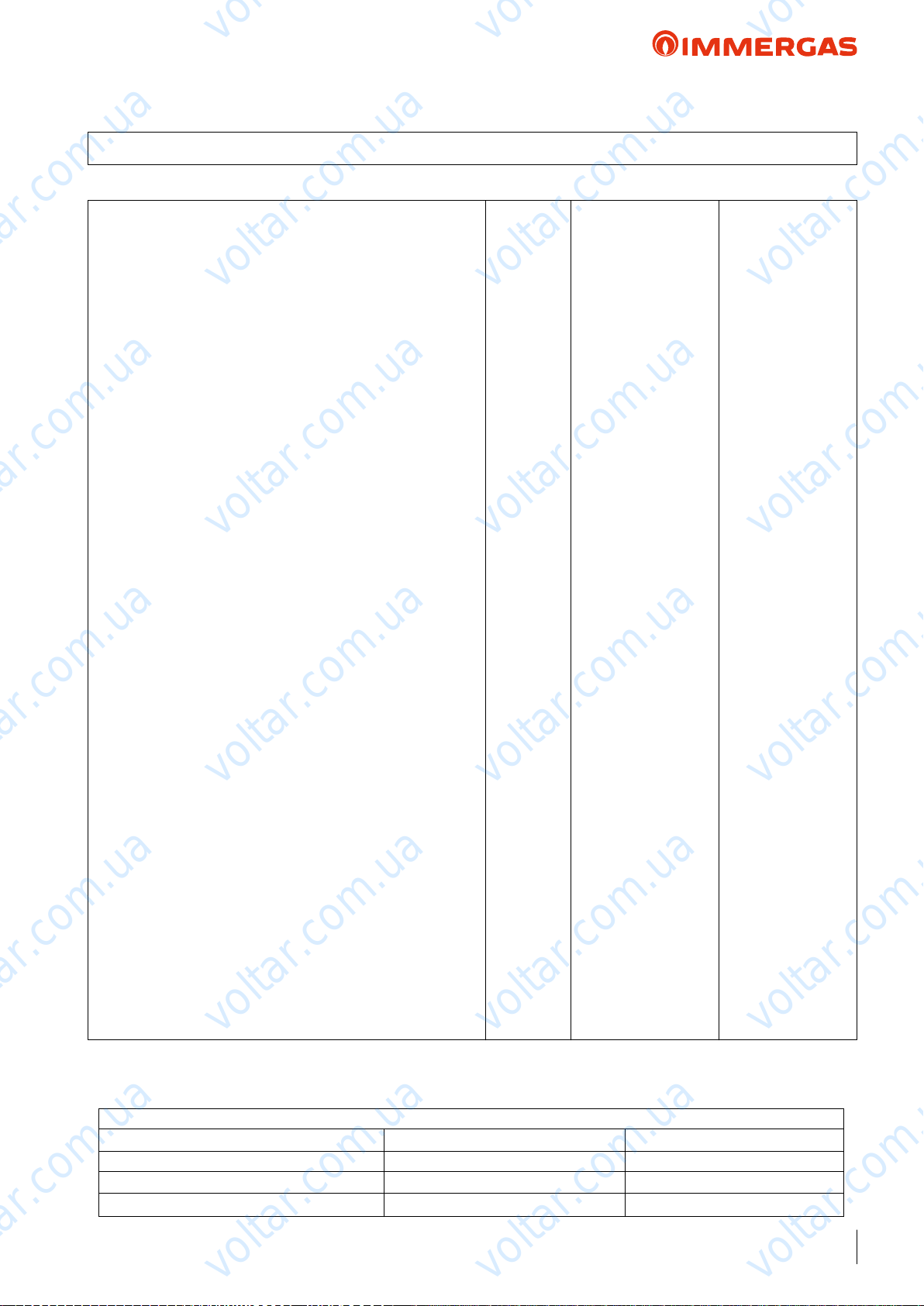
voltar.com.ua
voltar.com.ua
AUDAX TOP 21 ErP
30 AUDAX TOP 21 ErP TECHNICAL DATA
Central heating circuit
Power in CH mode with water set at 35 °C
Power in CH mode with water set at 45 °C
Power in CH mode with water set at 55 °C
CH mode COP with water set at 35 °C
CH mode COP with water set at 45 °C
CH mode COP with water set at 55 °C
Min/max heat power with water set at 35 °C
Min/max heat power with water set at 45 °C
Min/max heat power with water set at 55 °C
Flow temperature range °C 20 / 57
Outdoor temp. limits for Heating mode operation °C - 20 / 30
voltar.com.ua
(1)
kW 21.10
(2)
kW 19.97
(3)
kW 19.07
(1)
4.10
(2)
3.30
(3)
2.50
(1)
kW 8.90/30.45
(2)
kW 8.48 / 29.59
(3)
kW 7.89/23.24
voltar.com.ua
voltar.com.ua
voltar.com.ua
Cooling circuit
Power in cooling mode with water set at 18 °C
Power in cooling mode with water set at 7 °C
Cooling mode EER with water set at 18 °C
Cooling mode EER with water set at 7 °C
Min/max cooling capacity with water set at 18 °C
Min/max cooling capacity with water set at 7 °C
Flow temperature range °C 5 / 18
Outdoor temp. limits for Cooling mode operation °C 0 / 46
General data
System max. working pressure bar 3
Head available on the system with 2700 l/h flow rate kPa (m c.a.) 85 (8.65)
Expansion vessel capacity l 8
C.H. sound power level dB(A) 74
Appliance electric protection rating IP X4
Electric power supply V - Hz 400 - 50
Permitted voltage range V 360 - 440
Maximum power absorbed W 12400
Maximum current absorbed A 19.1
Fuse inserted A 25 - Type C
Refrigerant fluid load (R410A)* g 8000
Heat pump Weight kg 199.4
voltar.com.ua
(1)
kW 25.80
(2)
kW 18.58
(1)
3.80
(2)
3.10
(1)
kW 11.97 / 30.67
(2)
kW 8.67/23.08
voltar.com.ua
voltar.com.ua
voltar.com.ua
voltar.com.ua
voltar.com.ua
voltar.com.ua
voltar.com.ua
voltar.com.ua
* Hermetically sealed system.
THE REPORTED DATA REFERS TO THE FOLLOWING CONDITIONS (in compliance with EN 14511)
ROOM HEATING PHASE (°C) COOLING PHASE (°C)
Water TEMP. (F/R)
Water TEMP. (F/R)
Water TEMP. (F/R)
(1)
- AIR (db/wb) 35/30 - 7/6 18/23 - 35 (bs)
(2)
- AIR (db/wb) 45/40 - 7/6 7/12 - 35 (bs)
(3)
- AIR (db/wb) 55/47 - 7/6
voltar.com.ua
voltar.com.ua
:
55
voltar.com.ua
Page 56
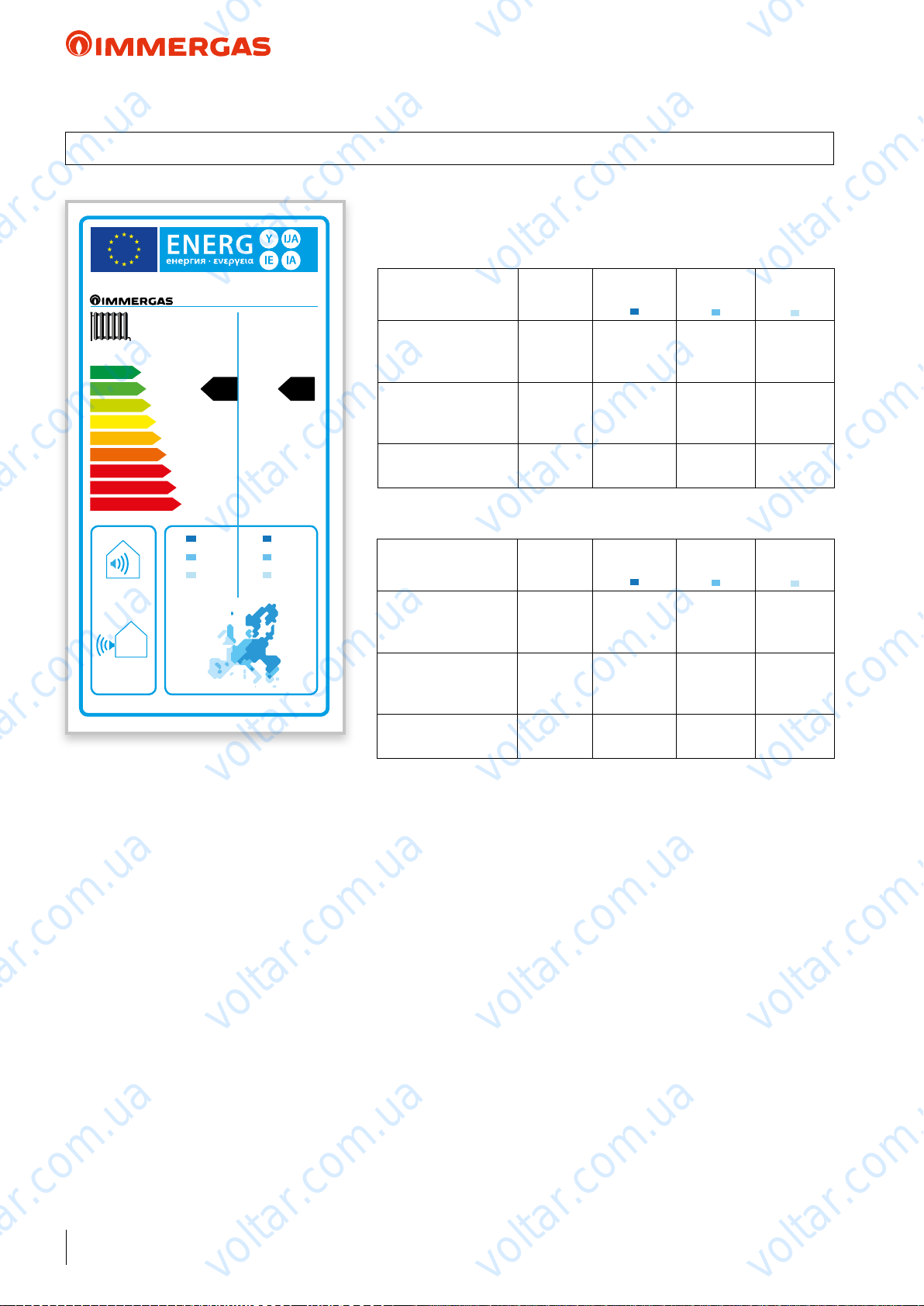
voltar.com.ua
voltar.com.ua
AUDAX TOP 21 ErP
31 PRODUCT FICHE REGULATION 811/2013
AUDAX TOP 21 ErP
Low temperature (30/35)
voltar.com.ua
AUDAX TOP 21 ErP
Parameter Value
voltar.com.ua
Colder
zones
Average
zones
voltar.com.ua
Hotter
voltar.com.ua
zones
++
A
A
+
A
B
A
C
B
D
C
D
E
E
F
F
G
G
74dBdB
55 °C 35 °C
+
A
22,77 24,47
15,07 16,64
16,37 21,06
kW kW
Annual energy consumption for the central
+
A
voltar.com.ua
heating function (QHE)
Room central heating
seasonal eciency (η
Nominal heat output kW 24.47 16.64 21.06
Average temperature (47/55)
Parameter Value
Annual energy consumption for the central
heating function (QHE)
Room central heating
seasonal eciency (η
Nominal heat output kW 22.77 15.07 16.37
kWh/year 19152 9625 5764
ηs % 117 139 192
)
s
voltar.com.ua
Colder
zones
kWh/year 22602 10889 5983
ηs % 92 111 143
)
s
Average
zones
voltar.com.ua
Hotter
zones
voltar.com.ua
voltar.com.ua
voltar.com.ua
voltar.com.ua
voltar.com.ua
voltar.com.ua
56
voltar.com.ua
voltar.com.ua
voltar.com.ua
Page 57
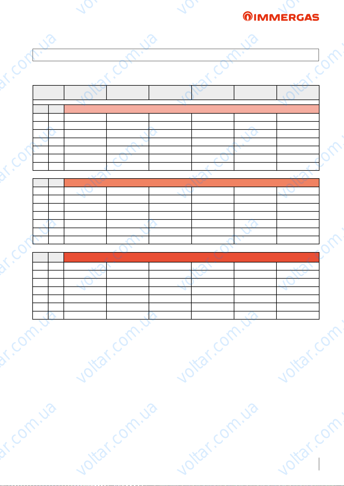
voltar.com.ua
voltar.com.ua
AUDAX TOP 21 ErP
32 AUDAX TOP 21 ErP ''POWER'' AND ''COP'' CENTRAL HEATING
• TOL = -20 °C
voltar.com.ua
Room Antifreeze air °C
d.b. (w.b.) Water ow temperature 35 °C
10 (9) 22.88 10.33 32.72 4.48 3.80 3.62
7 (6) 21.10 8.90 30.45 4.10 4.37 3.43
2 (1) 15.62 7.27 22.79 2.90 3.08 2.47
-7 (-8) 10.39 6.96 15.31 2.51 2.59 2.22
-10 (-11) 9.56 6.36 10.30 2.37 2.41 2.35
-15 (-16) 7.57 5.40 7.58 2.15 2.13 2.15
-20 (-21) 6.32 4.49 6.40 1.93 1.87 1.92
d.b. (w.b.) Water ow temperature 45 °C
10 (9) 21.71 9.72 31.49 3.59 2.86 2.99
7 (6) 19.97 8.48 29.59 3.30 3.37 2.61
2 (1) 14.83 6.84 21.67 2.34 2.41 2.03
-7 (-8) 9.74 6.47 14.70 1.99 2.02 1.80
-10 (-11) 8.94 5.88 9.66 1.89 1.89 1.87
-15 (-16) 7.00 4.96 7.01 1.71 1.68 1.71
-20 (-21) 5.84 4.06 5.85 1.54 1.49 1.54
d.b. (w.b.) Water ow temperature 55 °C
10 (9) 20.47 9.06 24.92 2.92 2.21 2.73
7 (6) 19.07 7.89 23.24 2.50 2.63 2.36
2 (1) 13.70 6.37 17.02 1.90 1.91 1.83
-7 (-8) 9.03 5.95 11.28 1.60 1.60 1.55
-10 (-11) 8.24 5.37 8.98 1.52 1.50 1.52
-15 (-16) -- -- -- -- -- --
-20 (-21) -- -- -- -- -- --
Output (kW)
Nom.
Output (kW)
Min.
voltar.com.ua
voltar.com.ua
voltar.com.ua
Output (kW)
Max.
COP (EN 14511)
Nom.
COP (EN 14511)
Min.
COP (EN 14511)
Max.
voltar.com.ua
voltar.com.ua
voltar.com.ua
voltar.com.ua
voltar.com.ua
voltar.com.ua
voltar.com.ua
voltar.com.ua
voltar.com.ua
voltar.com.ua
voltar.com.ua
57
voltar.com.ua
Page 58
voltar.com.ua
voltar.com.ua
AUDAX TOP 21 ErP
32.1 AUDAX TOP 21 ErP ''POWER'' AND ''EER'' CENTRAL HEATING
voltar.com.ua
Room Antifreeze air °C
d.b. Water ow temperature 18 °C
45 21.38 9.38 23.08 2.83 3.03 2.77
35 25.81 11.97 30.67 3.80 4.24 3.05
25 27.70 10.52 32.63 4.79 5.57 3,85
15 29.16 9.71 35.50 5.79 5.30 4.92
10 28.87 19.85 35.49 5.67 5.92 5.01
d.b. Water ow temperature 15 °C
45 19.76 8.62 21.34 2.70 2.83 2.65
35 23.40 11.00 28.49 3.36 3.91 2.95
25 25.65 9.60 30.32 4.59 4.99 3.74
15 26.75 9.30 32.59 5.40 5.76 4.65
10 26.91 18.43 32.59 5.56 5.63 4.72
d.b. Water ow temperature 10 °C
45 17.21 7.45 18.60 2.47 2.51 2.43
35 20.43 9.50 25.03 3.09 3.42 2.77
25 22.45 8.23 26.69 4.23 4.22 3.53
Output (kW)
Nom.
voltar.com.ua
voltar.com.ua
Output (kW)
Min.
Output (kW)
Max.
EER (EN 14511)
Nom.
EER (EN 14511)
Min.
EER (EN 14511)
Max.
voltar.com.ua
voltar.com.ua
voltar.com.ua
voltar.com.ua
15 22.83 7.91 28.12 4.64 4.60 4.19
10 23.27 16.18 28.40 4.95 5.13 4.35
d.b. Water ow temperature 7 °C
45 15.79 6.79 17.07 2.34 2.33 2.30
35 18.58 8.67 23.08 3.10 3.33 2.65
25 20.65 14.38 24.63 4.02 4.27 3.40
15 21.12 13.24 25.69 4.49 3.26 3.93
10 21.57 14.90 25.83 4.83 4.83 4.02
d.b. Water ow temperature 5 °C
45 14.86 6.37 16.08 2.25 2.21 2.22
35 17.70 8.14 21.82 2.96 3.14 2.57
25
15 20.02 12.51 24.01 4.38 3.12 3.69
10 20.47 14.08 23.95 4.73 4.63 3.68
voltar.com.ua
19.50 13.54 32.31 3.87 4.06 3.30
voltar.com.ua
voltar.com.ua
voltar.com.ua
voltar.com.ua
voltar.com.ua
58
voltar.com.ua
voltar.com.ua
voltar.com.ua
Page 59
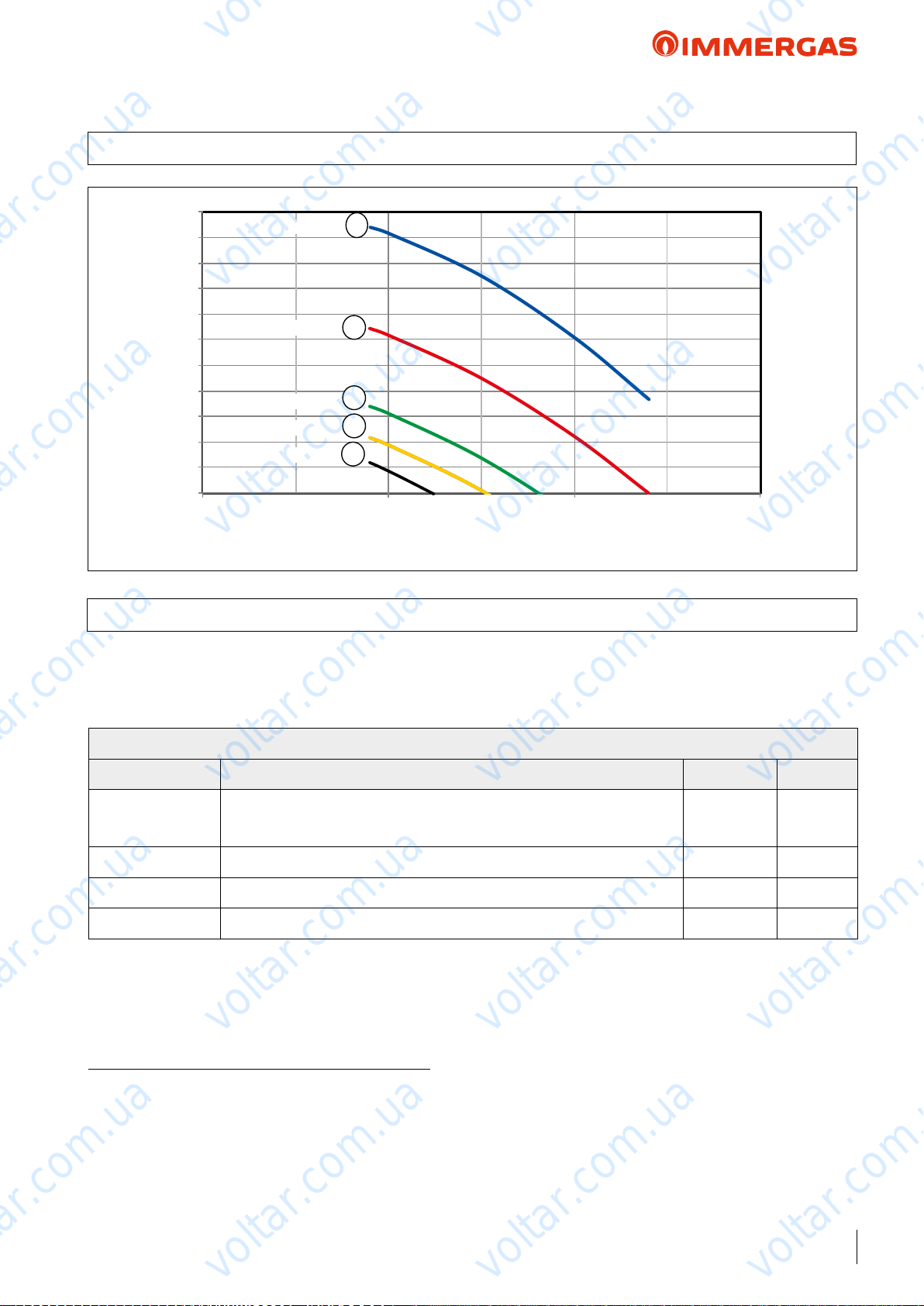
voltar.com.ua
voltar.com.ua
AUDAX TOP 21 ErP
33 GRAPH OF AUDAX TOP 21 ErP PUMP FLOW RATE/HEAD
voltar.com.ua
110
100
90
80
70
60
50
Head (kPa)
40
30
20
10
0
0 1800
All curves have been dened in constant pressure mode with various speeds.
33.1 AUDAX TOP 21 ErP PUMP SETTINGS AND CONFIGURATIONS
AUDAX TOP 21 ErP range boilers are supplied with a low power
consumption pump with variable speed control and settable
according to the following settings.
Speed 100%
1
voltar.com.ua
Speed 75%
Speed 50%
Speed 38%
Speed 25%
900 2700 3600 4500 5400
voltar.com.ua
2
3
4
5
Flow rate l/h
voltar.com.ua
voltar.com.ua
voltar.com.ua
voltar.com.ua
Assistance Menu -> System denition
Menu item Description Range Default
Pump control
Minimum speed Value of minimum speed used in modulating operation. 19% ÷ 50% 50%
Maximum speed Value of maximum speed used in modulating operation. 50% ÷ 100% 100%
Delta T Temperature delta to be maintained with modulating operation. 2 ÷ 20 5
TECHNICAL NOTE: System minimum water content:
To facilitate proper execution of the AUDAX TOP ErP heat pump defrost cycles, a minimum water content in the system is required,
which must be: 6 l/kW of the machine's power for any type of system. e ywheel guarantees normal operation of AUDAX TOP ErP
with systems divided into zones (with variable water content in circulation). e ywheel also guarantees proper operation with fan coils
used for cooling (a condition in which the ow temperature is very low and has signicant heat load variations that vary the number of
active fan coils). It is also important to check that the dehumidier line has a minimum of 3 l/kW of the machine (dehumidier hydraulic
circuit connection).
voltar.com.ua
Enable the pump operation with speed set “Max.speeed” or the modulating mode
with tracking of the “Modulating” temperature dierential.
voltar.com.ua
voltar.com.ua
voltar.com.ua
Max.speed/
Modulating
voltar.com.ua
Modulating
voltar.com.ua
voltar.com.ua
voltar.com.ua
59
voltar.com.ua
Page 60
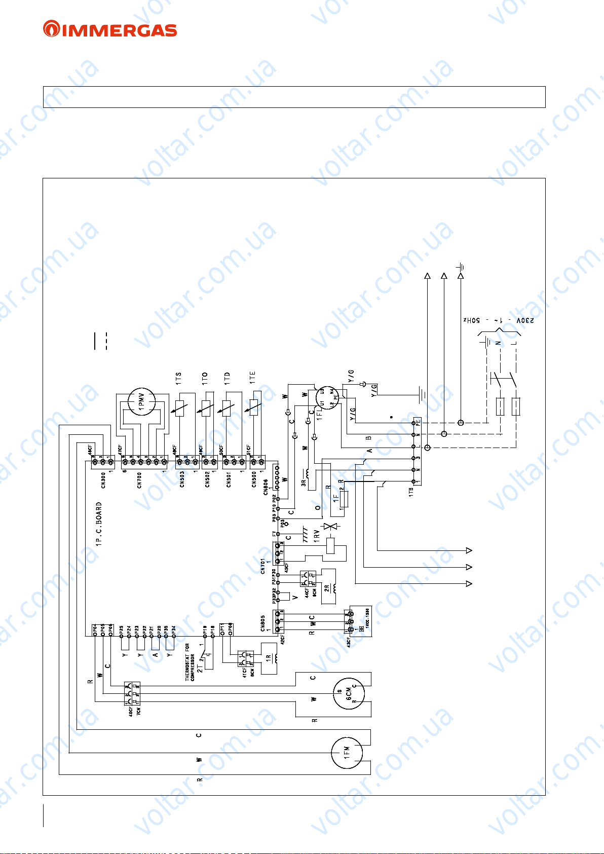
voltar.com.ua
34 AUDAX TOP 6 8 ErP P.C.B.
voltar.com.ua
voltar.com.ua
AUDAX TOP ErP
e AUDAX TOP 6 and 8 ErP heat pumps are designed to
function correctly, also without system Manager. ey must only
be set from the Control Panel (standard supply).
Remember to install a circuit breaker switch (you can also add a
voltar.com.ua
probe
= Manufacturer's wiring
= Installer's wiring
probe
voltar.com.ua
FL = Filter
F = Fuse
R = Inductance
PMV = Modulating valve motor
TE = Condenser pipe temperature probe
TD = High-pressure pipe temperature
TO = Outdoor unit temperature probe
TS = Low-pressure pipe temperature
RV = Reversing valve (4-way)
FM = Fan motor
CM = Compressor motor
KEY:
disconnecting switch, which is not supplied with the machine).
voltar.com.ua
voltar.com.ua
O = Orange
Y = Yellow
Cable colour:
R = Red
A = Brown
C = Black
V = Purple
B = Blue
Y/G = Yellow/Green
W = White
L
N
A
B
Y/G
voltar.com.ua
voltar.com.ua
voltar.com.ua
voltar.com.ua
voltar.com.ua
A
B
C
voltar.com.ua
voltar.com.ua
voltar.com.ua
60
voltar.com.ua
voltar.com.ua
voltar.com.ua
Page 61
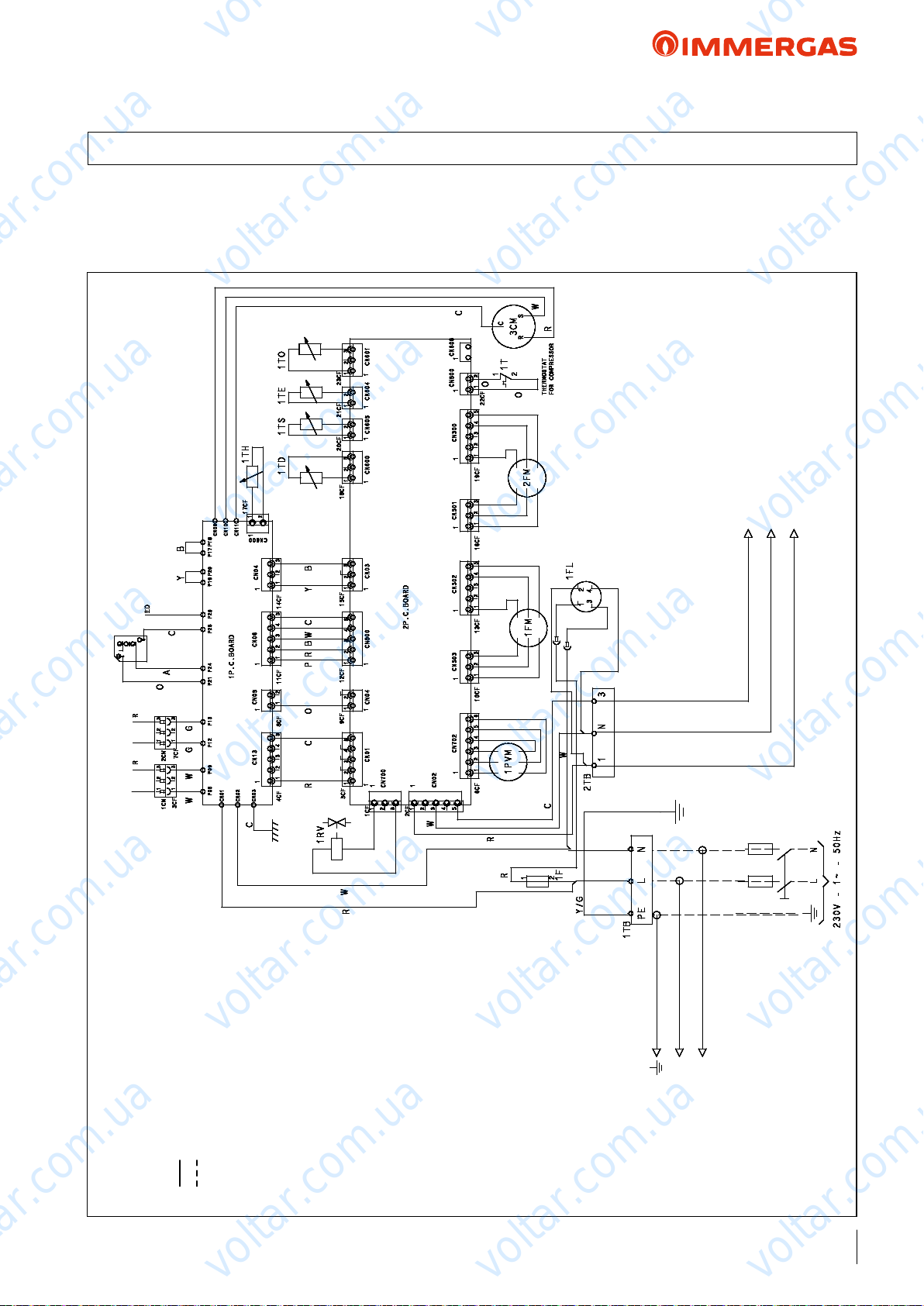
voltar.com.ua
voltar.com.ua
AUDAX TOP ErP
34.1 AUDAX TOP 12 ErP P.C.B.
voltar.com.ua
e AUDAX TOP 12 ErP heat pumps are designed to function
correctly, also without system Manager. ey must only be set
from the Control Panel (standard supply).
Remember to install a circuit breaker switch (you can also add a
voltar.com.ua
voltar.com.ua
disconnecting switch, which is not supplied with the machine).
voltar.com.ua
voltar.com.ua
voltar.com.ua
voltar.com.ua
C
B
A
= Manufacturer's wiring
= Installer's wiring
K EY:
voltar.com.ua
voltar.com.ua
TS = Low-pressure pipe temperature probe
TO = Outdoor unit temperature probe
TD = High-pressure pipe temperature probe
TE = Condenser pipe temperature probe
PMV = Modulating valve motor
R = Inductance
CM = Compressor motor
FM = Fan motor
RV = Reversing valve (4-way)
F = Fuse
Cable colour:
R = Red
Y = Yellow
O = Orange
voltar.com.ua
Y/G
AAB
voltar.com.ua
Y/G
A = Brown
C = Black
V = Purple
B = Blue
W = White
P = Pink
G = Grey
Y/G = Yellow/Green
B
L
N
voltar.com.ua
voltar.com.ua
61
voltar.com.ua
voltar.com.ua
voltar.com.ua
Page 62
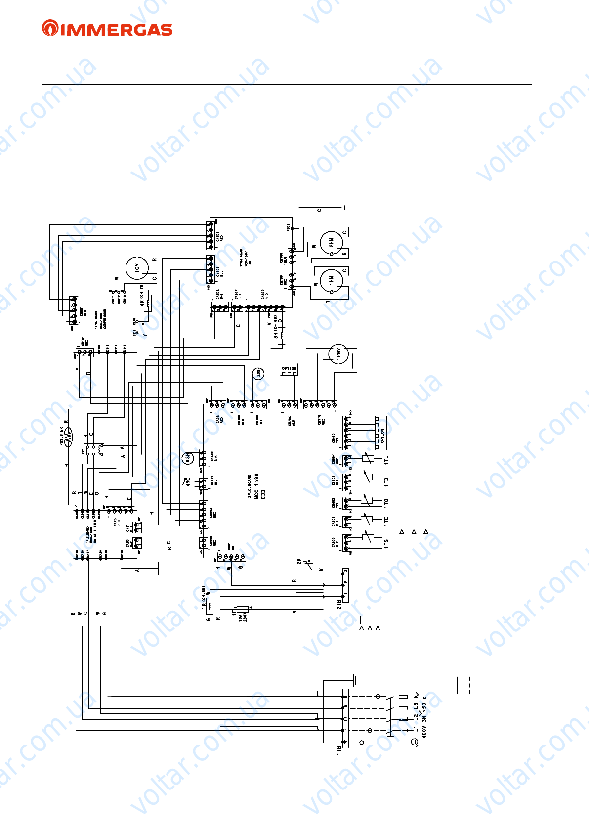
voltar.com.ua
34.2 AUDAX TOP 16 ErP P.C.B.
voltar.com.ua
voltar.com.ua
AUDAX TOP ErP
e AUDAX TOP 16 ErP heat pumps are designed to function
correctly, also without system Manager. ey must only be set
from the Control Panel (standard supply).
Remember to install a circuit breaker switch (you can also add a
voltar.com.ua
voltar.com.ua
disconnecting switch, which is not supplied with the machine).
voltar.com.ua
Cable colour:
R = Red
Y = Yellow
O = Orange
A = Brown
C = Black
voltar.com.ua
voltar.com.ua
V = Purple
B = Blue
W = White
P = Pink
G = Grey
Y/G = Yellow/Green
voltar.com.ua
voltar.com.ua
voltar.com.ua
voltar.com.ua
TO = Outdoor unit temperature probe
TD = High-pressure pipe temperature probe
TE = Condenser pipe temperature probe
TL = Condenser pipe temperature probe 2
PMV = Modulating valve motor
C
B
A
L
N
R = Inductance
voltar.com.ua
= Installer's wiring
KEY:
= Manufacturer's wiring
voltar.com.ua
F = Fuse
C = Compressor thermostat
H = High pressure switch
RY = Relay
voltar.com.ua
CM = Compressor motor
FM = Fan motor
SF = Reversing valve
TS = Low-pressure pipe temperature probe
62
voltar.com.ua
voltar.com.ua
voltar.com.ua
Page 63
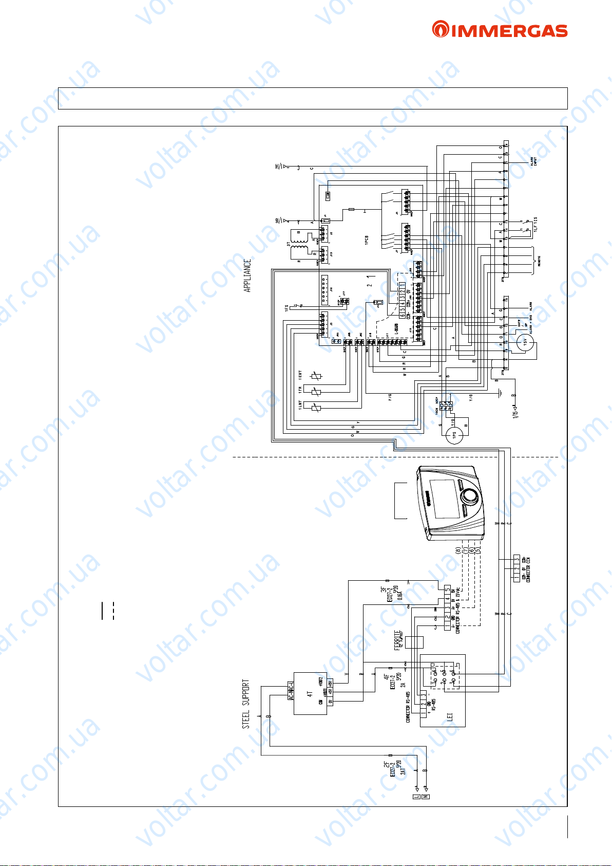
voltar.com.ua
voltar.com.ua
AUDAX TOP ErP
35 AUDAX TOP 6 8 12 16 ErP CONTROL DIAGRAM
voltar.com.ua
Cable colour:
R = Red
Y = Yellow
O = Orange
voltar.com.ua
voltar.com.ua
A = Brown
C = Black
G = Grey
B = Blue
W = White
V = Purple
Y/G = Yellow/Green
voltar.com.ua
voltar.com.ua
voltar.com.ua
voltar.com.ua
= Installer's wiring
KEY:
= Manufacturer's wiring
voltar.com.ua
LWT = Outlet water sensor
TR = Coolant sensor
FS = Flow switch
T = Transformer
PS = Water pump motor
-HTR = Electric heater
OAT = Outdoor air probe
LF = Frequency limitation
IS = DHW inlet
SV = DHW 3-way valve
R1 = Resistance
F = Fuse
voltar.com.ua
PANEL
REMOTE
voltar.com.ua
voltar.com.ua
voltar.com.ua
voltar.com.ua
voltar.com.ua
voltar.com.ua
63
voltar.com.ua
Page 64

voltar.com.ua
voltar.com.ua
AUDAX TOP ErP
36 AUDAX TOP 6 8 12 16 ErP TERMINAL BLOCK ELECTRICAL CONNECTIONS
Grey 5-pole terminal
block
voltar.com.ua
voltar.com.ua
CONTROL
PANEL
C W G Y 13 14 15 76321821 23 24
voltar.com.ua
N.B.: With system Manager applications, the Control Panel
(standard) can also function as a room temperature/humidity
probe of a system's zone. Refer to the chapter with regard to
examples of application diagrams on pages 88 to 103 for the
electrical connections.
AUDAX TOP ErP TERMINAL BLOCK PIN
Description PIN Signal Limits
1 3-way valve 10 - 18 - N Output 230Vac (18-N: Supply voltage, 10: signal) 1 ph ~ 230V, 2A
2 Alarm 11 - N Output, Relay Contact 1 ph ~ 230V, 2A
3 Auxiliary Pump 12 - N Output, Relay Contact 1 ph ~ 230V, 2A
Auxiliary Heat Source (e.g. electrical resistance)
4
5 Alarm 5 - N Output, Relay Contact 1 ph ~ 230V, 2A
6 Compressor Maximum Frequency Reduction 13 - 14 Input (contacts quality switch >25mA@12V) N.A.
7 DHW request 13 - 15 Input (contacts quality switch >25mA@12V) N.A.
8 Alarm input (external) 21 - 3 Input (contacts quality switch >25mA@12V) N.A.
S1 On (On = closed) / O (O = open) 6 - 3 Potential-free contact N.A.
S2 Central Heating (closed) / Cooling (open) 7 - 3 Potential-free contact N.A.
voltar.com.ua
4 - N Output, Relay Contact 1 ph ~ 230V, 2A
N N 18 10 11 12 4 5 16
voltar.com.ua
41
2
3
voltar.com.ua
6
7
5
8
voltar.com.ua
voltar.com.ua
voltar.com.ua
voltar.com.ua
S1
S2
64
Remove the panel (refer to the g. on the side) to see the electrical components on the front. e electrical supply voltage
voltar.com.ua
cables can be inserted in the holes set up. You must clamp the
electrical cables using group cable ties in order to prevent them
from touching the compressor and hot pipes.
e unit can be controlled and set by means of:
• Control Panel (standard).
• Switches or thermostats (not supplied).
Refer to the gure above for electrical connections.
N.B.: the quality of the contacts must be higher than 25mA @
12V. You are always required to install a circuit breaker switch.
voltar.com.ua
voltar.com.ua
voltar.com.ua
voltar.com.ua
voltar.com.ua
Page 65
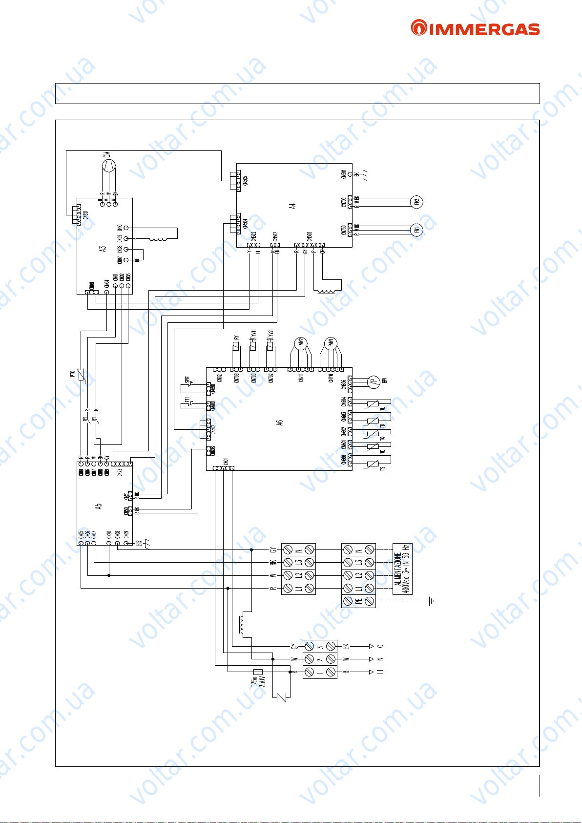
voltar.com.ua
voltar.com.ua
AUDAX TOP ErP
37 AUDAX TOP 18 21 ErP P.C.B.
voltar.com.ua
voltar.com.ua
voltar.com.ua
voltar.com.ua
voltar.com.ua
TE - Coil sensor low part
TL - Coil sensor high part
TO - Outdoor temperature sensor
TS - Compressor intake temperature
voltar.com.ua
sensor
voltar.com.ua
YV21 - Central heating solenoid valve
YV41 4-way valve control
voltar.com.ua
voltar.com.ua
Wiring colour codes:
BK - Black
BL - Blue
BR - Brown
GY - Grey
Y - Yellow
O - Orange
P - Pink
R - Red
W - White
voltar.com.ua
FM2 - Fan
FT1 - Compressor safety thermostat
PMV1 - rottle valve control
PMV2 - rottle valve control
voltar.com.ua
KEY:
A3 - Compressor inverter
A4 - Fans inverter
A5 - Filter
voltar.com.ua
(only for 21 kW model)
RY - Relay
SP1F - High pressure switch
TD - Compressor outlet temperature probe
voltar.com.ua
A6 - Interface board
BP1 - Pressure sensor (LP)
CM - Compressor
FM1 - Fan
voltar.com.ua
voltar.com.ua
65
voltar.com.ua
Page 66
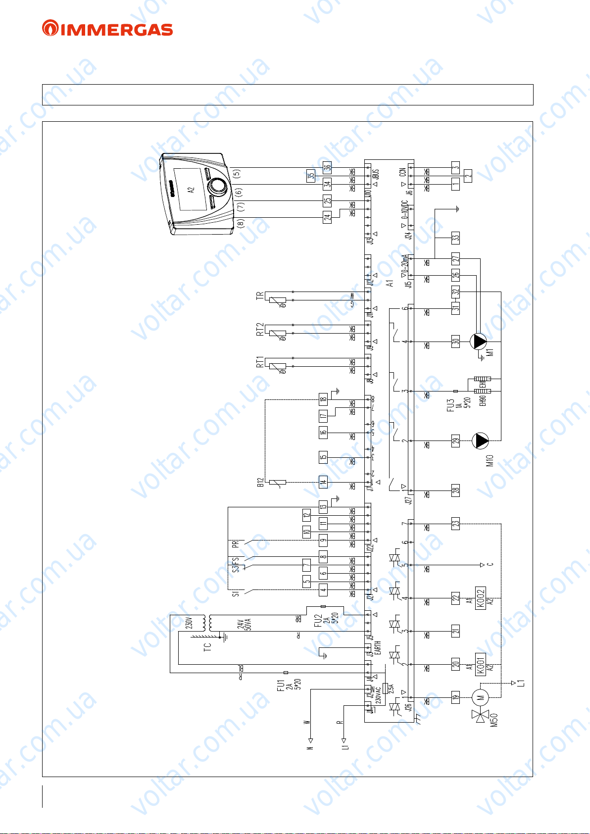
voltar.com.ua
voltar.com.ua
AUDAX TOP ErP
38 AUDAX TOP 18 21 ErP CONTROL DIAGRAM
voltar.com.ua
M1 - Heat pump circulator
M10 - Additional pump
M50 - DHW 3-way valve
PR - Power reduction enabling
voltar.com.ua
PANEL
CONTROL
voltar.com.ua
RT1 - Flow sensor
RT2 - Return sensor
S1 - Room thermostat
S3 - External safety inlet
TC - Transformer
TR - Coolant sensor
voltar.com.ua
voltar.com.ua
voltar.com.ua
voltar.com.ua
sensor
KEY:
A1 - Main control board (NHC)
A2 - Control panel
B12 - Domestic hot water temperature
EH1 - Plate exchanger heater
R - Red
BR - Brown
BL - Blue
G - Green
Wiring colour codes:
BK - Black
voltar.com.ua
EH90 - Hydraulic unit heater
FS - Flow switch
K001 - System integration
K002 - DHW Integration
voltar.com.ua
W - White
voltar.com.ua
voltar.com.ua
voltar.com.ua
voltar.com.ua
66
voltar.com.ua
voltar.com.ua
voltar.com.ua
Page 67
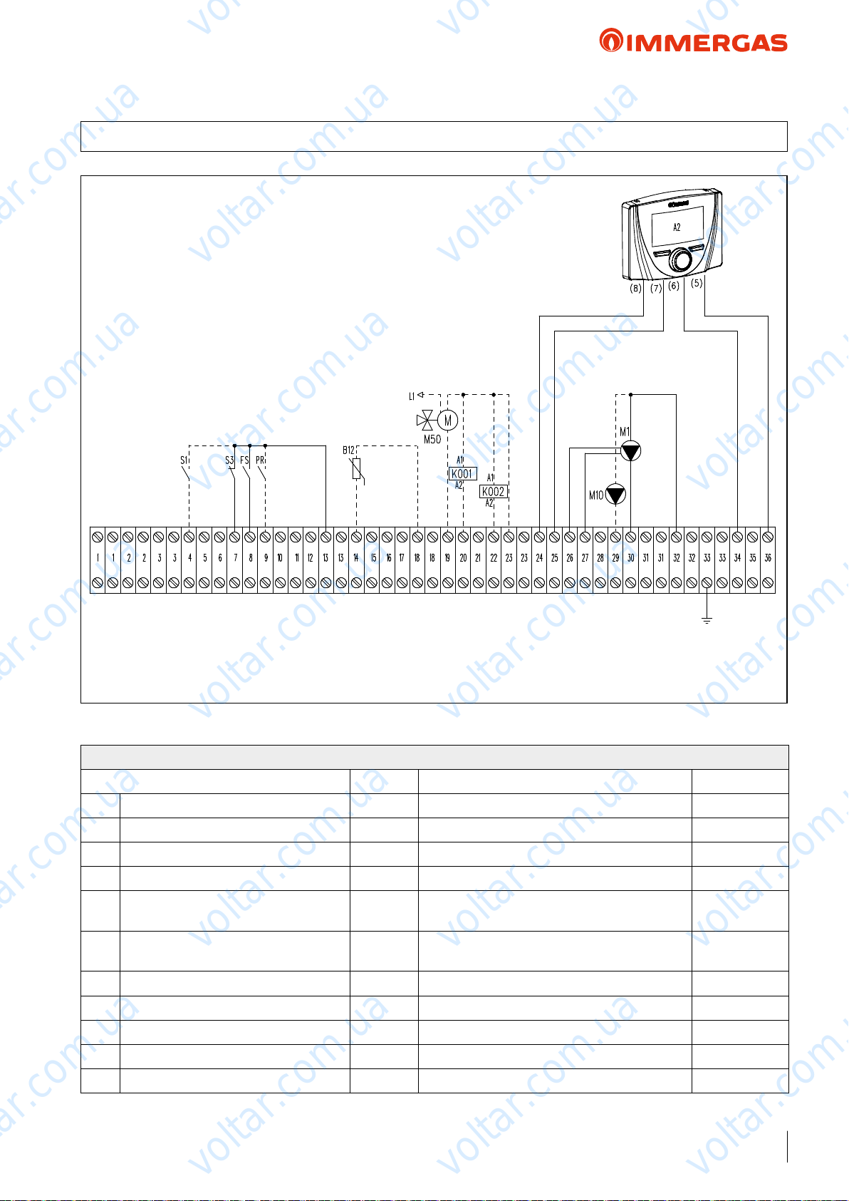
voltar.com.ua
voltar.com.ua
AUDAX TOP ErP
39 AUDAX TOP 18 21 ErP TERMINAL BLOCK ELECTRICAL CONNECTIONS
KEY:
A2 - Control panel
B12 - Domestic hot water temperature sensor
FS - Flow switch
K001 - System integration
K002 - DHW Integration
M1 - Heat pump circulator
M10 - Additional pump
M50 - DHW 3-way valve
PR - Power reduction enabling
S1 - Room thermostat
S3 - External safety inlet
voltar.com.ua
voltar.com.ua
CONTROL
PANEL
voltar.com.ua
voltar.com.ua
voltar.com.ua
PLEASE NOTE: With system Manager applications, the Control Panel (standard) can also function as a room temperature/
humidity probe of a system's zone. Refer to the chapter with regard to examples of application diagrams on pages 88 to 103
for the electrical connections.
voltar.com.ua
AUDAX TOP 18 - 21 ErP TERMINAL BLOCK PIN
Description PIN Signal Limits
M1 Heat pump Internal circulator 30 - 32 Output, Relay Contact 1 ph ~ 230V, 2A
M1 Internal circulator modulation control 26 - 27 PWM Control - -
M10 Additional / booster pump 29 - 32 Output, Relay Contact 1 ph ~ 230V, 2A
M50 DHW 3-way valve 19 - 23 - L1 Output 230Vac (23-L1: Supply voltage, 19: signal) 1 ph ~ 230V, 2A
System Integration
K001
(electrical resistance control)
20 - 23 Output, Relay Control 1 ph ~ 230V
voltar.com.ua
voltar.com.ua
voltar.com.ua
voltar.com.ua
D.H.W. (Domestic hot water) Integration
K002
(electrical resistance control)
B12 D.H.W. request probe 14 - 18 NTC Probe 10 kohm 25 °C - -
FS Flow switch 8 - 13 Input (contacts quality switch >25mA@12V) N.A.
Compressor Maximum Frequency Reduction
PR
S1 Room thermostat (On = closed) 4 - 13 Input (contacts quality switch >25mA@12V) N.A.
S3 External safety inlet 7 - 13 Input (contacts quality switch >25mA@12V) N.C.
voltar.com.ua
22 - 23 Output, Relay Control 1 ph ~ 230V
9 - 13 Input (contacts quality switch >25mA@12V) N.A.
voltar.com.ua
voltar.com.ua
voltar.com.ua
voltar.com.ua
voltar.com.ua
67
Page 68
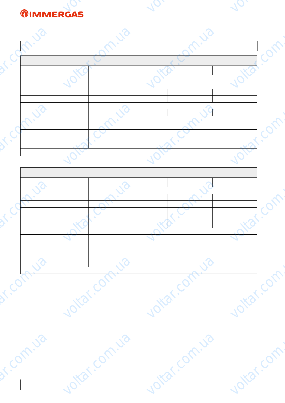
voltar.com.ua
voltar.com.ua
AUDAX TOP ErP
40 ELECTRIC CONNECTION CABLES FEATURES
AUDAX TOP 6 - 8 - 12 ErP (Mono-phase)
Unit 6 kW 8 kW 12 kW
Power Supply V - ph - Hz 230 - 1 - 50
Permitted voltage range V 207 ÷ 253
Maximum power absorbed kW 2 2.7 3.85
Maximum current absorbed A 11 14.5 20.7
Supply voltage fuses
Supply voltage cable section mm
Supply voltage cable type H07RN-F
Maximum length m 50
External pump circulation maximum
current
voltar.com.ua
A 16 - Type B 16 - Type B 25 - Type D
2
(per phase) 3 x 2.5 mm
A 2
Use H03VV-F 5x0.75 mm² cables to connect the Control Panel
voltar.com.ua
gL Type
2
voltar.com.ua
voltar.com.ua
voltar.com.ua
AUDAX TOP 16 - 18 - 21 ErP (ree-phase)
Unit 16 kW 18 kW 21 kW
Power Supply V - ph - Hz 400 - 3 +N - 50
Permitted voltage range V 376 ÷ 424 360 ÷ 440 360 ÷ 440
Maximum power absorbed kW 6.5 10.8 12.4
Maximum current absorbed A 11.1 16.7 19.1
Supply voltage fuses
Supply voltage cable section mm
Supply voltage cable Max. section mm2 (per phase) 5G x 6 mm
Supply voltage cable type H07RN-F
Maximum length m 80
External pump circulation maximum
current
voltar.com.ua
Use H03VV-F 5x0.75 mm² cables to connect the Control Panel
A 16 - Type B 25 - Type C 25 - Type C
2
(per phase) 5G x 4 mm
A 2
voltar.com.ua
gL Type gG Type gG Type
2
2
voltar.com.ua
voltar.com.ua
voltar.com.ua
68
voltar.com.ua
voltar.com.ua
voltar.com.ua
voltar.com.ua
voltar.com.ua
voltar.com.ua
Page 69
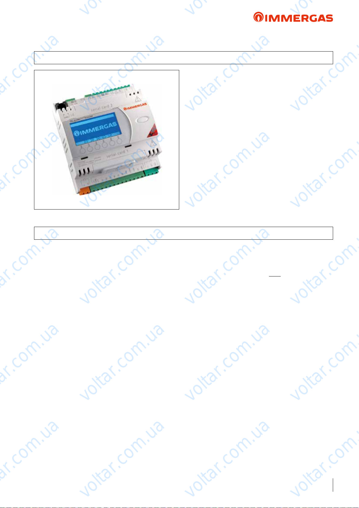
voltar.com.ua
voltar.com.ua
AUDAX TOP ErP and Integrated System
41 SYSTEM MANAGER
It is an electronic controller with microprocessor, realised with
the objective of being a "unique manager" for integrated systems.
anks to this innovative supervisor, it is possible to establish
and activate the most convenient heat source depending on
functional, environmental and "economic" parameters.
voltar.com.ua
In fact, to control everything, the System manager must acquire
voltar.com.ua
the data relative to the external temperature (from the external
probe) and the system ow temperature (relative to the pre-set
climatic curve),after having congured the fuel cost parameter
(e.g. methane gas) and that of the electric energy.
Designed to enhance climatic comfort, it allows you to set
dierent climatic curves for each zone, both for hot and cold.
e user interface is made up from an LCD with matrix and a
6-key membrane keyboard.
Installation takes place on a guide for electric components from
control board.
voltar.com.ua
voltar.com.ua
voltar.com.ua
41.1 TECHNICAL FEATURES
Using the system manager (integrated with the relative expansion
kits) it is possible to control:
• up to 4 AUDAX TOP ErP heat pumps in set conguration;
• Immergas boiler;
• storage tank for D.H.W. production (the D.H.W. temperature
is managed by the NTC probe.
• room C.H. storage tank (the temperature inside the tank is
managed by the NTC probe);
• up to 2 solar circulation units for systems with manifolds
arranged on dierent slopes;
• temperature probes (NTC - PT1000);
• ON/OFF request dry contact;
• integrative electric resistance for DHW;
• integrative electric resistance for heat system;
• variable ow temperature of the heat pump and the boiler
(using the required models), depending on the external temperature (a climatic curve is pre-selected);
• 4 expansion boards to manage the air conditioning system (3 of
which for any mixed/not mixed zones and one used exclusively
in the high temp. zone that operates independently, connected
to the boiler circuit);
• 1 expansion board for the additional functions, namely:
- hot/cold switch-over on distinct systems (for example systems
with radiant panel heating and fan-coil cooling);
- recirculation pump management for DHW;
- acquisition of a signal from a system that generates electrical
energy (e.g. photovoltaic system);
voltar.com.ua
voltar.com.ua
voltar.com.ua
• up to 3 humidity-temp. sensors or 4 zone remote controls;
• up to 3 Dehumidiers.
On the other hand, in terms of the main settings that can/must
be carried out, the System Manager allows you to acquire or
programme:
• outdoor temperature (with a probe already installed on
voltar.com.ua
AUDAX TOP ErP);
• system ow temperature;
• storage tank temperature (even through 2-3 probes, 1 of which
refers to the solar-heated part of the boiler);
• by means of self-diagnosis, detection and display of error codes
in the event of anomalies;
• date and time;
• dierentiated selection and programming for each individual
zone;
• programming the time periods for DHW production;
• anti-legionella program (in a system where there is a boiler or
integrative resistance on the storage tank, in addition to the
voltar.com.ua
Heat Pump);
• cost of combustion (Methane or LPG);
• cost of the electric energy;
• management of the heat/cooling sources.
• SYSTEM MANAGER code 3.021522
voltar.com.ua
voltar.com.ua
voltar.com.ua
voltar.com.ua
voltar.com.ua
69
voltar.com.ua
Page 70
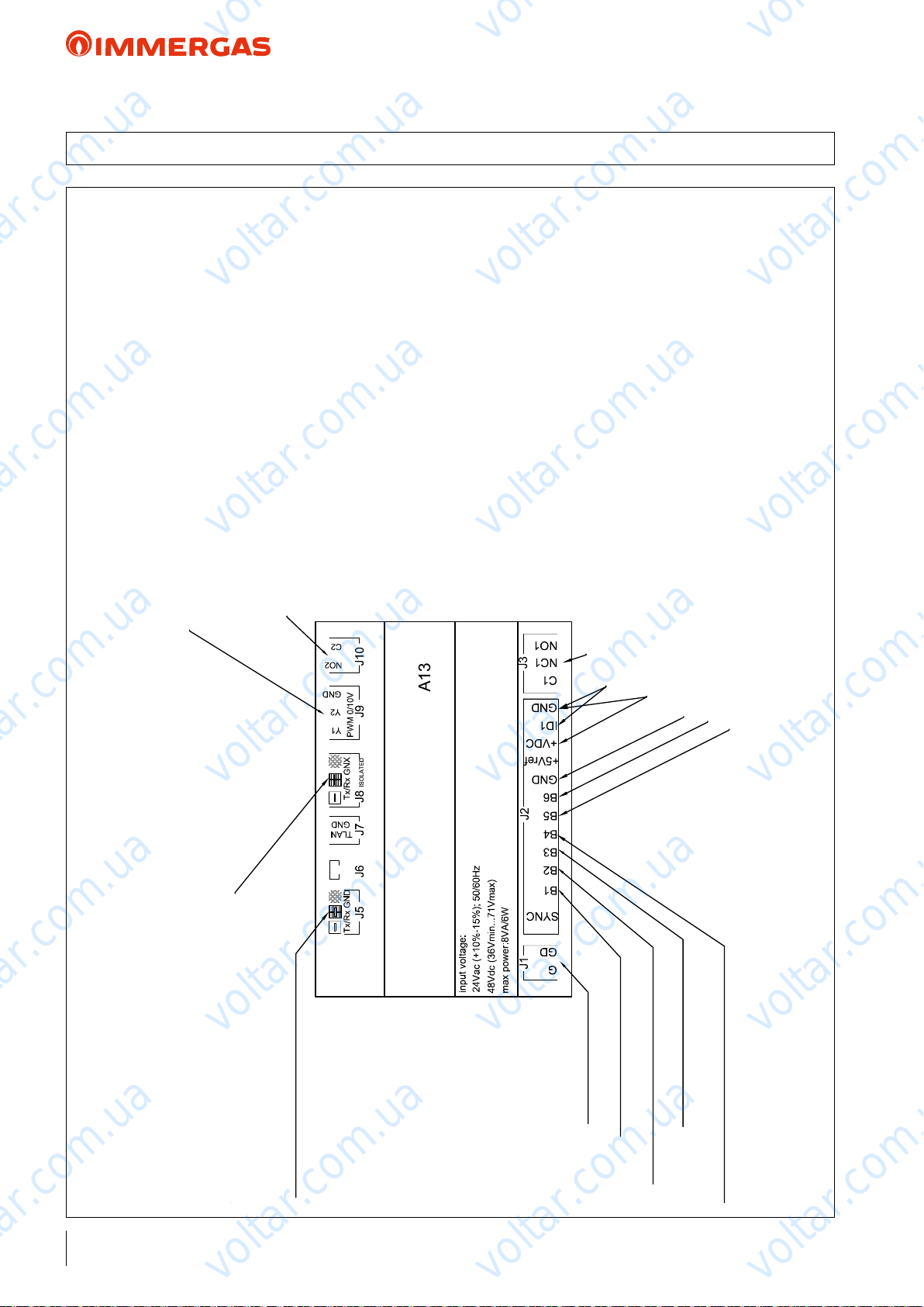
Expansion kit 3.021547 connections
Zone Remote Control connections 3.023364
(Zone control connections 3.021523)
Electric power supply
D.H.W. probe 3.019375
Solar system storage tank probe 3.019375
Solar panel probe 3.019374
voltar.com.ua
voltar.com.ua
AUDAX TOP ErP and Integrated System
41.2 SYSTEM MANAGER ELECTRICAL CONNECTIONS
voltar.com.ua
voltar.com.ua
voltar.com.ua
D.H.W. production diverter valve activation connection
Central heating/cooling diverter valve commutation connection with puffer.
Boiler connections
Relay connections code 3.023946 for central heating electrical integration
Relay connections code 3.023945 for D.H.W. electrical integration/boiler
activation with On/Off contact
voltar.com.ua
voltar.com.ua
voltar.com.ua
voltar.com.ua
Solar system circular connection
Safety thermostat jumper or room temperature with no
zone expansion
Control Panel supply voltage provided by
default with AUDAX TOP ErP
Common probes/inputs
Boiler alarm inputs
Puffer probe 3.019375
voltar.com.ua
voltar.com.ua
AUDAX TOP ErP connection
70
voltar.com.ua
voltar.com.ua
voltar.com.ua
voltar.com.ua
voltar.com.ua
voltar.com.ua
voltar.com.ua
Page 71
voltar.com.ua
voltar.com.ua
AUDAX TOP ErP and Integrated System
NOTE:
Electrical connection between the system Manager and
the boilers (except models: range VICTRIX TT ErP,
VICTRIX kW TT, VICTRIX MAIOR TT, VICTRIX EXA,
VICTRIX SUPERIOR ErP, VICTRIX ZEUS SUPERIOR
ErP, ARES CONDENSING ErP, HERCULES MINI
ErP, HERCULES CONDENSING ErP, HERCULES
CONDENSING ABT ErP and HERCULES SOLAR 200 ErP),
must be carried out via electronic relay (abbreviation EMR 12
Vdc code 3.023945);
41.3 TECHNICAL DATA
e System manager can be powered exclusively via transformer or relevant generator:
- direct power supply: 48 Vdc (36 Vmin…72 Vmax)
- alternating power supply: 24 Vac +10/-15 %, 50/60 Hz
e device has the following features:
- user interface via LCD with matrix
- membrane keyboard with 6 keys
- installation on DIN guide for electric components from control board
- dimensions: L 105 x H 110 x D 60
voltar.com.ua
voltar.com.ua
- the electrical connection between the System Manager and
the 2, 4 or 6 kW system integrative resistance kit must be set
up using a solid state electronic relay (abbreviation SSR 6 Vdc
code: 3.023946).
voltar.com.ua
voltar.com.ua
voltar.com.ua
voltar.com.ua
voltar.com.ua
Operating conditions -10° T 60 °C, 90% RH non-condensing
Degree of protection IP40 only on front panel
Class depending on protection against electric shock to be integrated on Class I and/or II equipment
Period of electric stress of the isolating parts long
Type of disconnection or micro switching micro switching
Category of resistance to heat and re Category D (UL94-V0)
Immunity against surges Category II
Ageing features (functioning hours) 80,000
N° of automatic operation handling cycles 100,000 (EN 60730-1); 30,000 (UL 873)
Class and structure of the software Class A
Surge immunity category Category III (IEC EN 61000-4-5)
voltar.com.ua
voltar.com.ua
voltar.com.ua
voltar.com.ua
voltar.com.ua
voltar.com.ua
voltar.com.ua
voltar.com.ua
71
voltar.com.ua
Page 72
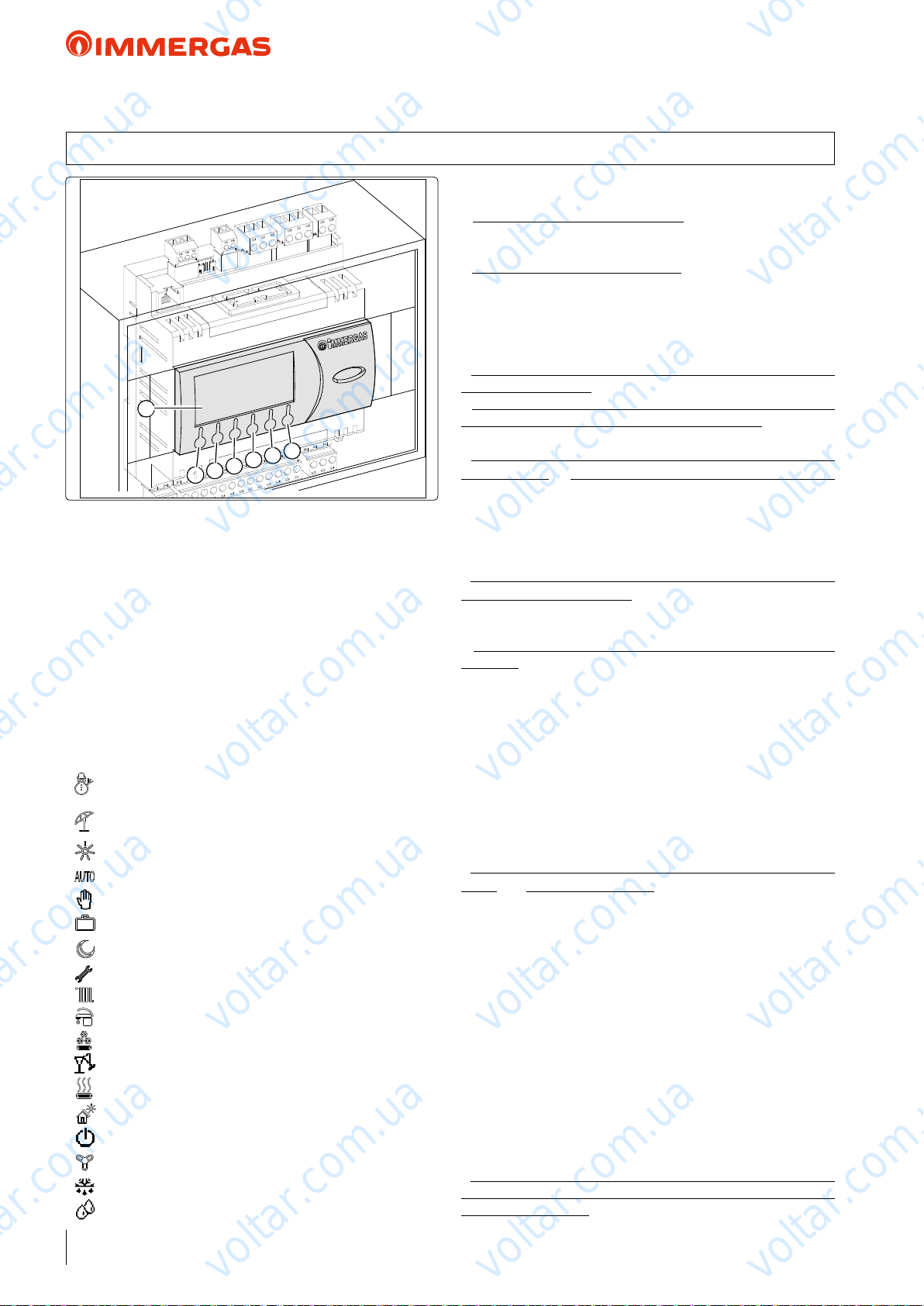
2
3
4
5
6
7
1
voltar.com.ua
voltar.com.ua
AUDAX TOP ErP and Integrated System
41.4 DESCRIPTION AND CONTROLS OF SPECIAL FUNCTIONS
The system Manager is equipped with several important
functions and application options:
• Set climatic curves for each zone, both for hot and cold;
maximum temperature of 85 °C, which can be selected for
all zones;
• Identify each zone independently: only hot, hot/cold, hot/
voltar.com.ua
is button (1) allows you to change the operating mode of the
system, specifically: Summer (only DHW and solar heating),
Summer with cooling, Winter, Party (all zones are set in comfort
mode), Standby (all requests are disabled: room antifreeze protection
< 5°C only remains active, if Immergas room probe is installed).
is button (2) allows you to access the submenus: Selection,
Programming, Info, Alarms log, Assistance.
is button (3) allows you to move back from a current menu
to the previous one.
ese buttons (4 and 5) allow you to scroll through the menus
on the screen cyclically or to increase or decrease the value of
the various parameters.
e button (6) enables you to change the displayed data.
DISPLAY (7) description:
winter - room central heating and DHW production
functions are enabled;
summer - DHW production only is enabled;
comfort temperature is active;
operating with automatic program;
operating with manual program;
operating with holiday timer program;
operation with energy savings programme;
symbol indicating anomaly;
request for central heating in room in progres;
request for DHW in progress;
DHW heating and cooling program;
operating in “Party” mode;
request to heat or cool room;
solar panel operation in progress;
system in stand-by;
request for cooling in room in progress;
dehumidier with cooled air;
dehumidier with neutral air;
voltar.com.ua
voltar.com.ua
voltar.com.ua
cold with dehumidier and dew point calculation, cold only,
voltar.com.ua
cold only with dehumidier and dew point calculation. e
said dew point calculation function can also be enabled/
disabled if dehumidier management is disabled (e.g. with
another dehumidier system managed independently);
• Set the Tminimum integration (cut-o) or COP calculation
to use the heat pump;
• Optimise the ow temperature to the system by means of
probes situated on the secondary booster circuit (e.g. with a
hydraulic manifold);
• In the event of boiler integration, it is also possible to keep
AUDAX TOP ErP permanently active if COP is advantageous.
e Manager must be connected to the boiler via the external
probe clamps (range models VICTRIX TT ErP, VICTRIX
kW TT, VICTRIX MAIOR TT, VICTRIX EXA, VICTRIX
voltar.com.ua
SUPERIOR ErP and all models with SUPERIOR electronics refer to the list in the previous page);
• DHW production boiler management via the heat pump as
opposed to the solar system (AUDAX TOP ErP connected to
the lower coil, boiler connected to the upper coil), in order to
obtain renewable source coverage on DHW;
• Option to have remote-domotic management on the
Manager. 3 digital inputs are used on expansion address 5,
which, according to their status (open/closed), determine the
operation mode. Contact “domotic” management is executed
using the following options:
Standby (inputs ID1=0 ID2=0 ID3=0);
→ Winter (inputs ID1=1 ID2=0 ID3=0);
→ Summer (inputs ID1=1 ID2=1 ID3=0);
→ Cooling (inputs ID1=0 ID2=0 ID3=1);
voltar.com.ua
→ Party (inputs ID1=1 ID2=0 ID3=1);
→ Digital output 4 regarding expansion address 5 is enabled
in the event of a system anomaly (for an error message to be
sent to the domotic system);
• Input on expansion address 5 to force activation of AUDAX
TOP ErP with the FV system, which generates electricity
(refer to the diagram on the next page). By using an inverter/
electronic device that supplies a signal when FV production
exceeds a set value, a contact closes on expansion address 5,
which:
→Immediately brings the DHW storage tank to 50 °C, disabling
any programmed DHW time bands;
→e minimum COP functional convenience is reset and
Tminimum integration brought to -15 °C, thus removing
voltar.com.ua
integration from the boiler; the only thing that remains active
is the maximum time for the system to be fully operational,
beyond which the boiler is activated in order to guarantee
climatic comfort;
→If a puer system is congured in the menu, it is heated up
to 55 °C, even without request from the system; also in this
case, the only thing to remain active is the maximum time for
the system to be fully operational.
• Input on expansion address 4 to disable the generators (e.g.
boiler or electrical resistance remain on standby) when a
thermoue operates.
voltar.com.ua
voltar.com.ua
voltar.com.ua
voltar.com.ua
voltar.com.ua
72
voltar.com.ua
voltar.com.ua
voltar.com.ua
Page 73
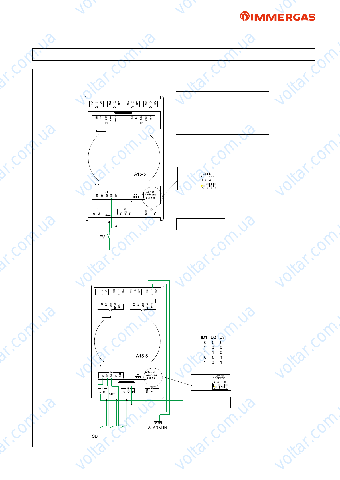
Key:
A15-5: Zone expansion kit with address 5
(code 3.021547)
DS: Domotic system.
Notes:
Configure the expansion address as indicated.
Contact “domotic” management is executed
using the following configurations:
Stand-by
Winter
Summer
Cooling
Party
Expansion Addresses
Address 5
Supply voltage 24Vac;
voltar.com.ua
voltar.com.ua
voltar.com.ua
AUDAX TOP ErP and Integrated System
41.5 EXAMPLES OF EXPANSIONS WITH ADDRESS "4" AND "5" FOR AUXILIARIES
Photovoltaic contact management
Key:
voltar.com.ua
A15-5: Zone expansion kit with address 5
voltar.com.ua
(code 3.021547)
PV: On/Off contact from photovoltaic system.
Notes:
Configure the expansion address as indicated.
Expansion Addresses
voltar.com.ua
Address 5
voltar.com.ua
Contact management from domotic system
voltar.com.ua
Key:
A15-5: Zone expansion kit with address 5
(code 3.021547)
DS: Domotic system.
Notes:
Configure the expansion address as indicated.
Contact “domotic” management is executed
using the following configurations:
Stand-by
Winter
Summer
Cooling
Party
voltar.com.ua
Supply voltage 24Vac;
50Hz
voltar.com.ua
voltar.com.ua
voltar.com.ua
voltar.com.ua
voltar.com.ua
Expansion Addresses
voltar.com.ua
Address 5
Supply voltage 24Vac;
50Hz
voltar.com.ua
voltar.com.ua
73
voltar.com.ua
Page 74
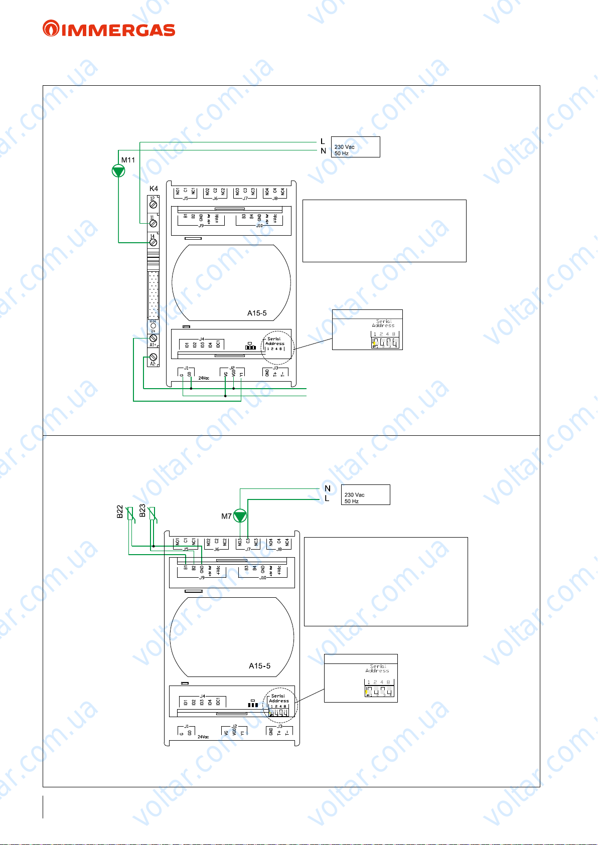
Key:
A15-5: Zone expansion kit with address 5
(code 3.021547)
PV: On/Off contact from photovoltaic system.
Notes:
Configure the expansion address as indicated.
Key:
A15-4: Zone expansion kit with address 4
(code 3.021547)
THERMOFLUE: On/Off contact from thermoflue.
Notes:
Configure the expansion address as indicated.
Input contact to disable the generators when a
thermal chimney is operating: if the contact
closes Audax, the boiler/resistance remain on
standby.
THERMOFLUE
Key:
A15-5: Zone expansion kit with address 5
(code 3.021547)
DS: Domotic system.
Notes:
Configure the expansion address as indicated.
Contact “domotic” management is executed
using the following configurations:
Stand-by
Winter
Summer
Cooling
Party
Expansion Addresses
Address 5
Expansion Addresses
Address 5
Supply voltage 24Vac;
50Hz
Supply voltage 24Vac;
Supply voltage 24Vac;
Expansion Addresses
Address 4
Key:
A15-4: Zone expansion kit with address 4
(code 3.021547)
THERMOFLUE: On/Off contact from thermoflue.
Notes:
Configure the expansion address as indicated.
Input contact to disable the generators when a
thermal chimney is operating: if the contact
closes Audax, the boiler/resistance remain on
standby.
THERMOFLUE
using the following configurations:
Stand-by
Winter
Summer
Cooling
Party
Expansion Addresses
Address 5
Supply voltage 24Vac;
50Hz
Supply voltage 24Vac;
50Hz
Expansion Addresses
Address 4
voltar.com.ua
AUDAX TOP ErP and Integrated System
Pump management downstream of the plate heat exchanger
voltar.com.ua
voltar.com.ua
voltar.com.ua
SUPPLY VOLTAGE
voltar.com.ua
Key:
A15-5: Zone expansion kit with address 5
(code 3.021547)
M11: Circulation downstream of the plate heat
exchanger on heat pumps.
K4: relay type EMR 12V DC code 3.023945
Expansion Addresses
Address 5
voltar.com.ua
Supply voltage
24Vac; 50Hz
voltar.com.ua
voltar.com.ua
voltar.com.ua
Pump management for thermal discharge
voltar.com.ua
Key:
A15-5: Zone expansion kit with address 5
(code 3.021547)
M7: thermal discharge circulation.
B22: hot source probe (code 3.019375).
B23: cold source probe (code 3.019375).
Notes:
Configure the expansion address as indicated.
voltar.com.ua
SUPPLY VOLTAGE
voltar.com.ua
Expansion Addresses
voltar.com.ua
Address 5
voltar.com.ua
voltar.com.ua
74
voltar.com.ua
voltar.com.ua
voltar.com.ua
Page 75
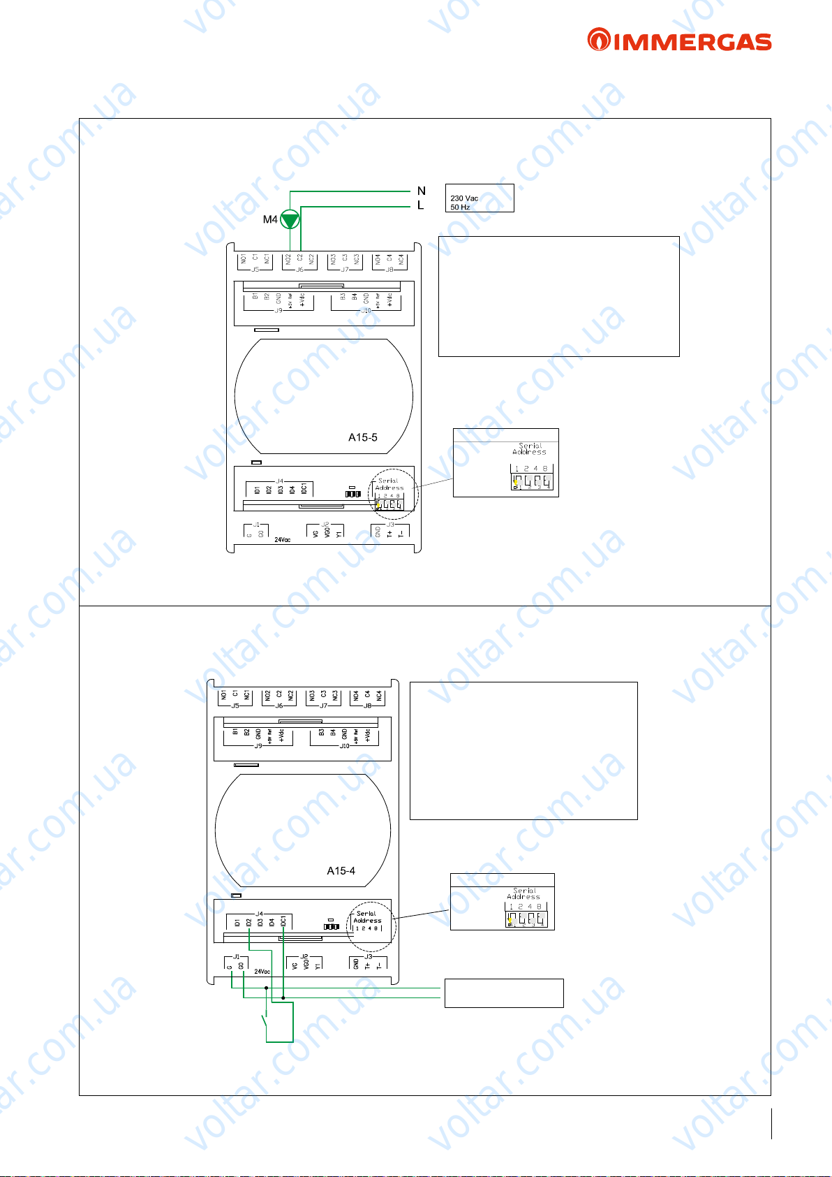
Key:
A15-5: Zone expansion kit with address 5
(code 3.021547)
DS: Domotic system.
Notes:
Configure the expansion address as indicated.
Contact “domotic” management is executed
using the following configurations:
Stand-by
Winter
Summer
Cooling
Party
Expansion Addresses
Address 5
Supply voltage 24Vac;
50Hz
Key:
A15-5: Zone expansion kit with address 5
(code 3.021547)
M11: Circulation downstream of the plate heat
exchanger on heat pumps.
K4: relay type EMR 12V DC code 3.023945
Key:
A15-4: Zone expansion kit with address 4
(code 3.021547)
THERMOFLUE: On/Off contact from thermoflue.
Notes:
Configure the expansion address as indicated.
Input contact to disable the generators when a
thermal chimney is operating: if the contact
closes Audax, the boiler/resistance remain on
standby.
THERMOFLUE
using the following configurations:
Stand-by
Winter
Summer
Cooling
Party
Expansion Addresses
Address 5
Expansion Addresses
Address 5
Supply voltage 24Vac;
50Hz
SUPPLY VOLTAGE
Supply voltage 24Vac;
Supply voltage 24Vac;
Supply voltage
24Vac; 50Hz
Expansion Addresses
Address 4
Expansion Addresses
Address 5
Expansion Addresses
Address 5
Key:
A15-5: Zone expansion kit with address 5
(code 3.021547)
M7: thermal discharge circulation.
B22: hot source probe (code 3.019375).
B23: cold source probe (code 3.019375).
Notes:
Configure the expansion address as indicated.
voltar.com.ua
AUDAX TOP ErP and Integrated System
DHW recirculation pump management
voltar.com.ua
voltar.com.ua
ermoue contact management
voltar.com.ua
SUPPLY VOLTAGE
Key:
voltar.com.ua
A15-5: Zone expansion kit with address 5 (code
3.021547)
M4: circulation of D.H.W. recirculation
Notes:
Configure the expansion address as indicated.
Expansion Addresses
Address 5
voltar.com.ua
voltar.com.ua
voltar.com.ua
voltar.com.ua
voltar.com.ua
voltar.com.ua
THERMOFLUE
Key:
voltar.com.ua
A15-4: Zone expansion kit with address 4
(code 3.021547)
THERMOFLUE: On/Off contact from thermoflue.
Notes:
Configure the expansion address as indicated.
Input contact to disable the generators when a
thermal chimney is operating: if the contact
closes Audax, the boiler/resistance remain on
standby.
Expansion Addresses
Address 4
voltar.com.ua
Supply voltage 24Vac;
50Hz
voltar.com.ua
voltar.com.ua
voltar.com.ua
voltar.com.ua
75
voltar.com.ua
Page 76
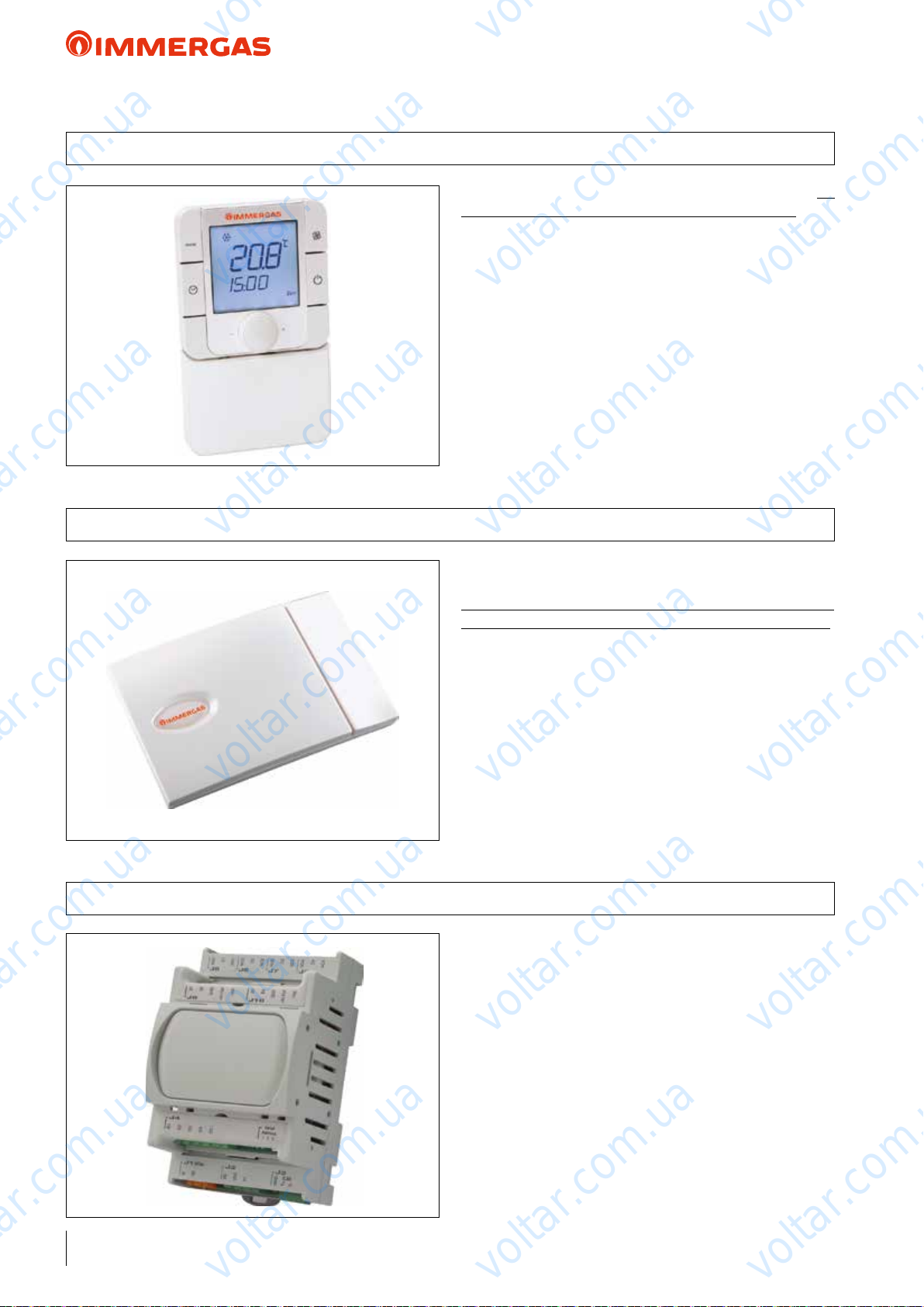
voltar.com.ua
voltar.com.ua
AUDAX TOP ErP and Integrated System
42 ZONE REMOTE CONTROL
It is an electronic device equipped with a back-lit display to
control and adjust the room's temperature and humidity. Connection to the system Manager is on the same BUS connection
as AUDAX TOP ErP and temperature-humidity probes.
It programs the relative room heat adjustment.
voltar.com.ua
It can be applied to the wall using the supplied screws and plugs.
voltar.com.ua
e kit must be powered at 230 Vac.
• OPTIONAL code 3.023364
voltar.com.ua
voltar.com.ua
43 ROOM TEMPERATURE/HUMIDITY SENSOR
44 EXPANSION BOARD FOR ZONE MANAGEMENT
voltar.com.ua
It is a room temperature and humidity probe, to be applied to
the wall.
Dierently to the zone remote control kit, in this case, the settings of all room parameters take place on the System Manager.
e kit must be connected directly to the expansion board for
zone management.
e kit must be powered at 24 Vac.
voltar.com.ua
• OPTIONAL code 3.021524
is component must be powered at 24 Vac and is mainly used
for system zone management; in particular n°1 expansion kit
must be used for each zone. e expansion kit manages pump,
mixing valve and the dehumidier of the same zone, acquiring
the room request (temperature and humidity) for a determined
voltar.com.ua
zone. e following can be connected to this kit:
- the room temperature - humidity sensor;
- an ON-OFF type request contact.
Installation takes place on a DIN guide for electric components
from control board. is board is envisioned as per standard
in the 2 kits for zone systems (see the following page).
voltar.com.ua
voltar.com.ua
voltar.com.ua
voltar.com.ua
voltar.com.ua
voltar.com.ua
76
• OPTIONAL code 3.021547
voltar.com.ua
voltar.com.ua
voltar.com.ua
Page 77
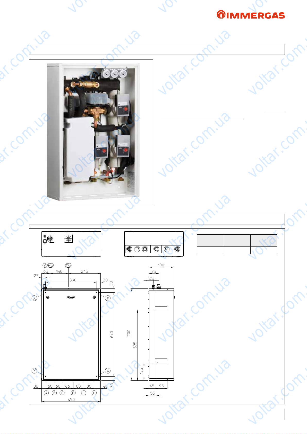
voltar.com.ua
voltar.com.ua
AUDAX TOP ErP and Integrated System
45 SYSTEM DISTRIBUTION KIT
Two pre-packaged systems called: "2 mixed zones kit" and "2
mixed zones and 1 direct zone kit". ey are comprised of
2 separate hydraulic manifolds (ow/return) + by-pass, thermometers to read the temperatures, motorised mixing valves,
low energy consumption electro pumps and expansion boards
voltar.com.ua
for electric management.
voltar.com.ua
e pumps included in the kit are distinguished for being very
elastic, also thanks to the 7 operating curves that can be pre-set.
All parts are already assembled and ready for operation exclusively
in combination with the System Manager. With the aid of the
expansions the 2 kits are governed by the System Manager during
the central heating and cooling phases.
Acquisition of the outdoor temperature from system Manager enables you to select independent ow temperature curves for each
of the 2 or 3 zones of the system (both with C.H. and cooling).
Inserting these kits into the technological system enhance overall
comfort and energy savings.
voltar.com.ua
voltar.com.ua
voltar.com.ua
45.1 DIMENSIONS AND CONNECTIONS
voltar.com.ua
voltar.com.ua
voltar.com.ua
KEY:
RG - Generator return (G 3/4”)
MG - Generator ow (G 3/4”)
V - Electrical connection
X - Holes for wall-mounted installation of the kit
• MIXED ZONES 2 KIT
code 3.021528
B - Zone return 1 (G 3/4”)
C - Zone return 2 (G 3/4”)
D - Zone ow 1 (G 3/4”)
E - Zone ow 2 (G 3/4”)
voltar.com.ua
Height
(mm)
700 450 190
Width
(mm)
voltar.com.ua
Depth
(mm)
voltar.com.ua
voltar.com.ua
voltar.com.ua
• 2 MIXED ZONES AND 1 DIRECT ZONE KIT
code 3.021527
A - Zone return 3 (G 3/4”)
B - Zone return 1 (G 3/4”)
C - Zone return 2 (G 3/4”)
D - Zone ow 1 (G 3/4”)
E - Zone ow 2 (G 3/4”)
F - Zone ow 3 (G 3/4”)
voltar.com.ua
voltar.com.ua
77
voltar.com.ua
Page 78
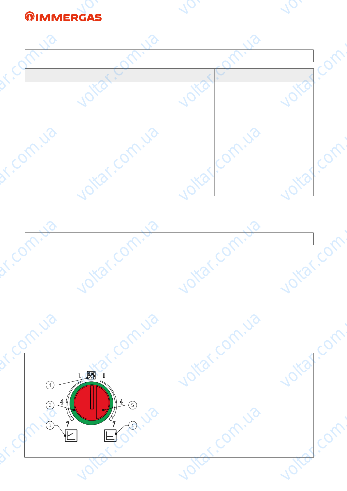
voltar.com.ua
voltar.com.ua
AUDAX TOP ErP and Integrated System
45.2 TECHNICAL DATA
voltar.com.ua
Mixed zones 2 kit
Maximum nominal pressure
Maximum operating pressure
Low temperature circuit minimum set point regulation temperature
Low temperature circuit maximum set point regulation temperature
Water content in device
Total head available in non-mixed zone with 1000 l/h ow rate (max)
Total head available in mixed zone (mixing valve closed)
with 1000 l/h ow rate (max.)
Empty device weight
Full device weight
Electrical connection
Maximum input
Installed electric power
Power in stand-by
Electric plant protection
Maximum distance between kit - heat pump or boiler
voltar.com.ua
voltar.com.ua
* = temperature can only be reached in combination with a boiler.
45.3 CIRCULATION PUMP SETTINGS AND CONFIGURATIONS
bar
°C
°C
°C
voltar.com.ua
l
kPa (m H
kPa (m H
kg
kg
V/Hz
A
W
W
-
m
O)
2
O)
2
voltar.com.ua
3
90*
25
50/85*
1.5
--
54.50 (5.50)
21.1
22.6
230/50
0.9
105
9.5
IP20
500
2 mixed zones and 1
direct zone kit
3
90*
25
voltar.com.ua
50/85*
1.9
43 (4.30)
54.50 (5.50)
23.1
25.0
230/50
1.2
150
9.5
IP20
500
voltar.com.ua
e kits are supplied with circulating pumps tted with speed
regulator. ese settings are suitable for most systems.
For proper operation one must select the most suitable type of
operation for the system and select a speed between 2 and 7.
- Program constant head (∆P C). The circulator pump
maintains the pressure level (head) constant as the system heat
demand decreases (ow rate reduction). With these settings,
the circulator pump is suitable for all oor systems where all
the circuits must be balanced for the same drop in head. One
can select the operating level from minimum to maximum by
turning the selector switch clockwise in the relative power scale
(refer to the drawing below).
voltar.com.ua
KEY:
voltar.com.ua
1 - Automatic vent mode operation
2 - Light ring to indicate the operating status
3 - Proportional head operation
4 - Constant head operation
5 - Operating mode selector switch
- Program proportional head (∆P V) . is allows the pressure
level (head) to be proportionally reduced as the system heat
demand decreases (ow rate reduction). anks to this function, the electric power consumption of the circulator pump is
reduced further: the energy (power) used by the pump decreases
according to the pressure level and ow rate. With this setting,
voltar.com.ua
the pump guarantees optimal performance in most heating systems, proving particularly suitable in single-pipe and two-pipe
installations. Any noise of the water ow in the pipes, valves
and radiators is eliminated by reducing the head. One can select
the operating level from minimum to maximum by turning the
selector switch anticlockwise on the relative power scale (refer
to the drawing below).
voltar.com.ua
voltar.com.ua
voltar.com.ua
78
voltar.com.ua
voltar.com.ua
voltar.com.ua
Page 79
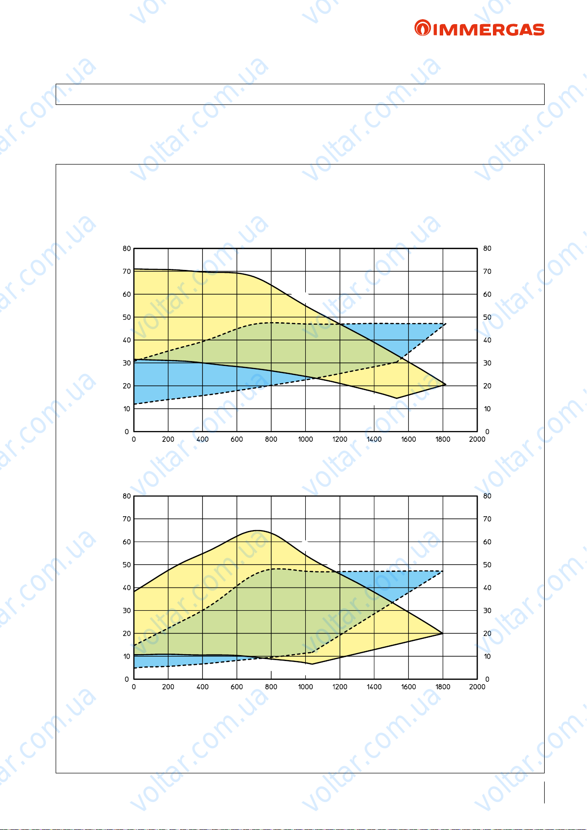
voltar.com.ua
voltar.com.ua
AUDAX TOP ErP and Integrated System
45.4 GRAPHS OF CIRCULATION PUMP FLOW RATEABSORPTIONHEAD
voltar.com.ua
e kit contains an electronic low consumption circulation
pump, whose ow rate/head features are shown in the graph
below.
voltar.com.ua
Constant head (∆P C).
ZONE MIXED WITH A CLOSED MIXING VALVE
WILO YONOS PARA RS 15-7 RKA CM 130
Speed 7
A
voltar.com.ua
Head (kPa)Head (kPa)
B
All pumps in the kit are suitable for operation with heat and
cold carrying uid.
voltar.com.ua
voltar.com.ua
Speed 2
voltar.com.ua
voltar.com.ua
Portata (l/h)
Flow rate (l/h)
Proportional head (∆P V).
voltar.com.ua
A
voltar.com.ua
Speed 2
voltar.com.ua
Speed 7
B
voltar.com.ua
Circulator pump absorbed power (W)Circulator pump absorbed power (W)
voltar.com.ua
voltar.com.ua
Flow rate (l/h)
KEY:
A = Head available at speed 2 ÷ 7
B = Power absorbed by the system circulator pump (dotted area)
voltar.com.ua
voltar.com.ua
EEI ≤ 0,20
79
voltar.com.ua
Page 80
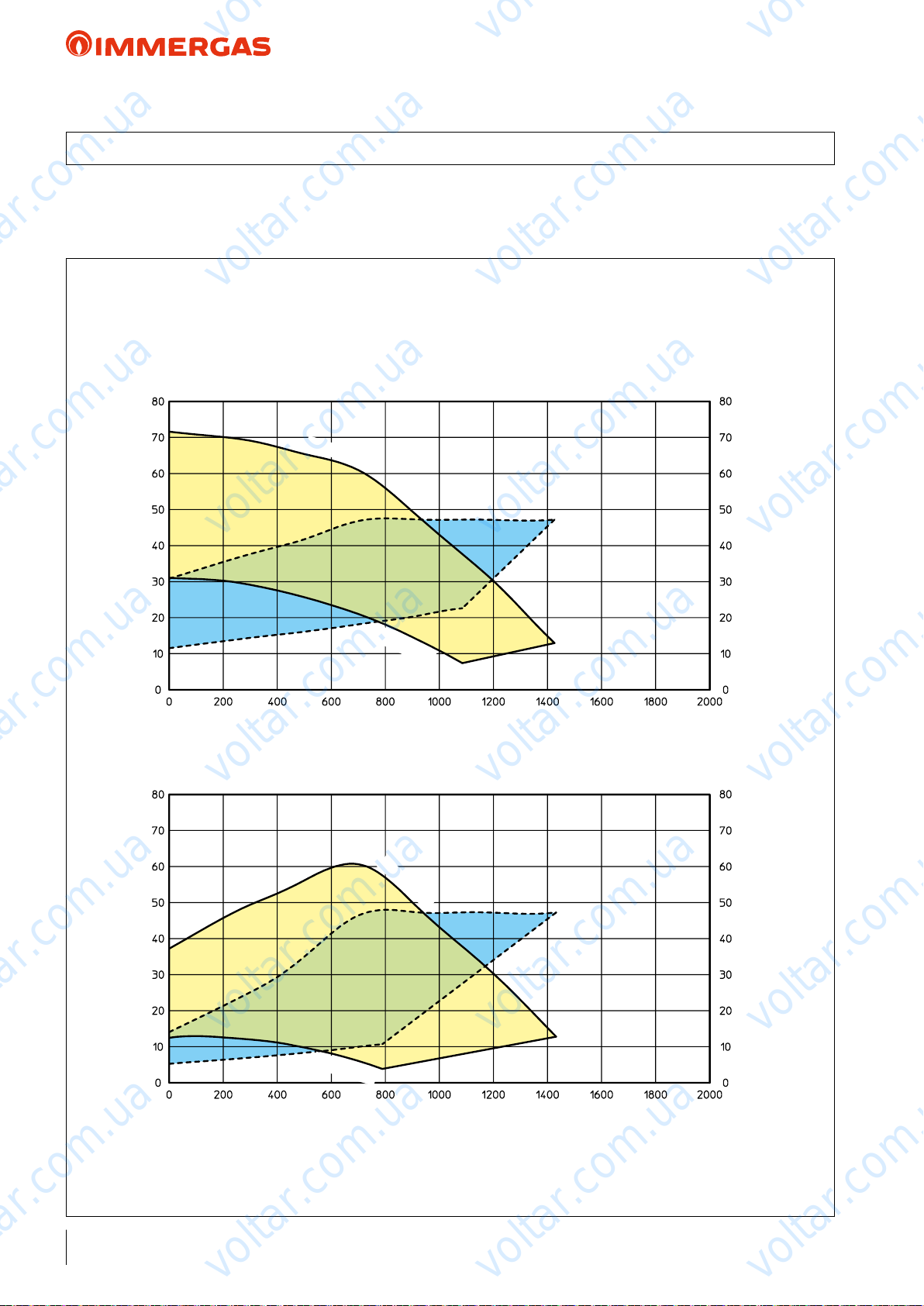
voltar.com.ua
voltar.com.ua
voltar.com.ua
AUDAX TOP ErP and Integrated System
45.5 GRAPHS OF CIRCULATION PUMP FLOW RATEABSORPTIONHEAD
e kit contains an electronic low consumption circulation
pump, whose ow rate/head features are shown in the graph
below.
voltar.com.ua
ZONE MIXED WITH AN OPEN MIXING VALVE AND DIRECT ZONE
WILO YONOS PARA RS 15-7 RKA CM 130
Constant head (∆P C).
Speed 7
A
voltar.com.ua
Head (kPa)Head (kPa)
B
Speed 2
All pumps in the kit are suitable for operation with heat and
cold carrying uid.
voltar.com.ua
voltar.com.ua
voltar.com.ua
voltar.com.ua
Circulator pump absorbed power (W)Circulator pump absorbed power (W)
Flow rate (l/h)
Proportional head (∆P V).
KEY:
A = Head available at speed 2 ÷ 7
B = Power absorbed by the system circulator pump (dotted area)
voltar.com.ua
Speed 7
A
voltar.com.ua
Speed 2
Flow rate (l/h)
voltar.com.ua
B
voltar.com.ua
voltar.com.ua
voltar.com.ua
EEI ≤ 0.20
80
voltar.com.ua
voltar.com.ua
voltar.com.ua
Page 81
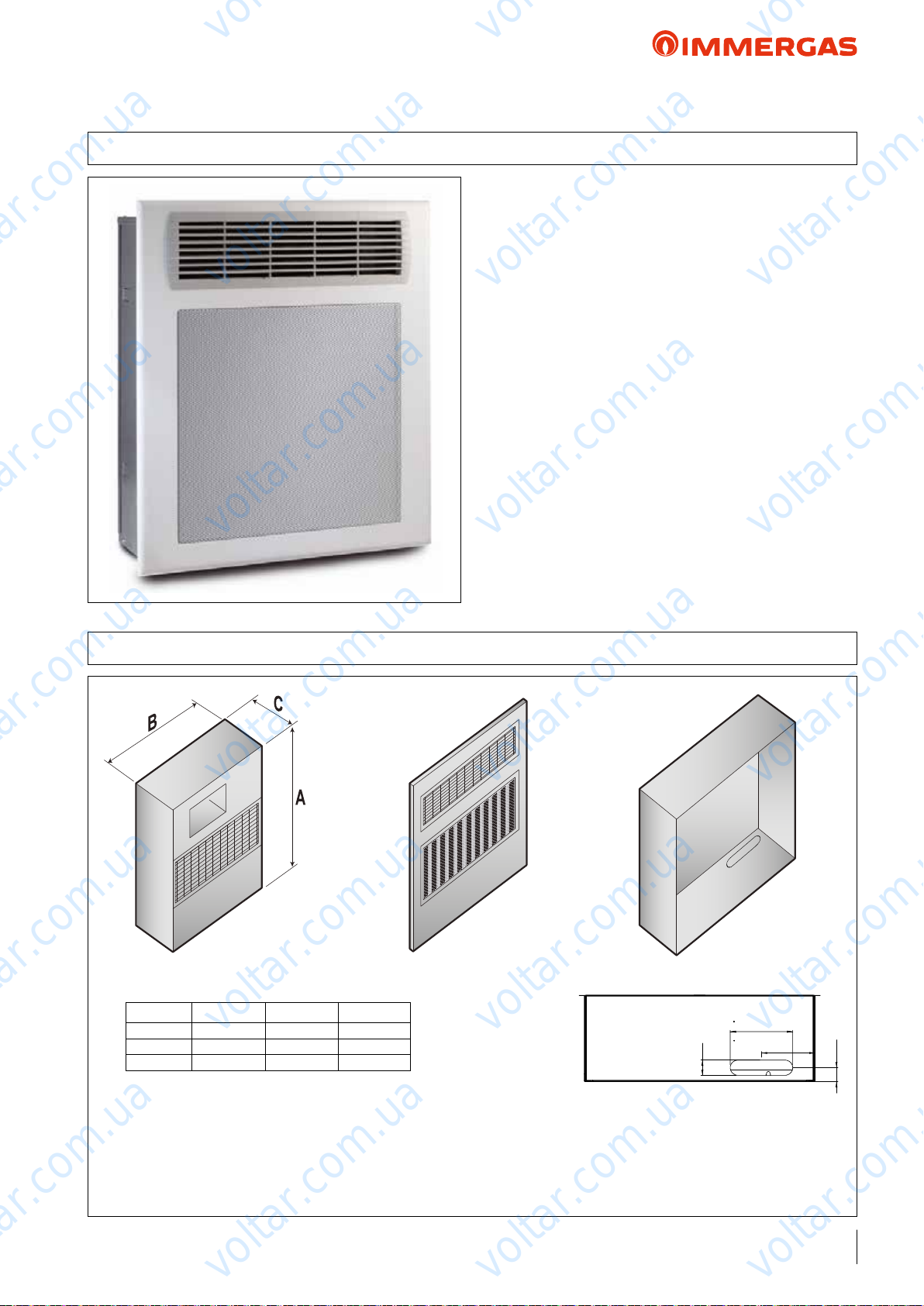
voltar.com.ua
voltar.com.ua
AUDAX TOP ErP and Integrated System
46 DEHUMIDIFIER
Designed to be coupled to cooling plants with radiant panels, the
dehumidier allows to keep the percentage of relative humidity
in the room within the comfort values, preventing the possible
formation of condensate on the walls.
e dehumidier, which is designed to be installed vertically on
voltar.com.ua
voltar.com.ua
the wall (recessed), has pre- and post-cooling coils.
voltar.com.ua
ese components allow excellent control of the air temperature
and humidity.
However, it can function without the aid of pre and post cooling
water coils, thus allowing to dehumidify when the cooling system
is o, typical of mid-season.
In compliance with European Directives, it has EC declaration
of conformity.
Dehumidication can take place:
- with neutral air: without variation of the air temperature,
dehumidies internal rooms;
- with cooled air:contributes to cooling the rooms, as well as
reducing the internal relative humidity.
voltar.com.ua
voltar.com.ua
voltar.com.ua
voltar.com.ua
46.1 DIMENSIONS AND CONNECTIONS
voltar.com.ua
1) Dehumidier
Model A
1 680 545 221
2 750 660 20
3 703 605 228
(mm) B (mm) C (mm)
voltar.com.ua
voltar.com.ua
2) Grid 3) Frame
voltar.com.ua
voltar.com.ua
164
voltar.com.ua
40
3.1) Frame bottom
140,5
36,6
• DEHUMIDIFIER code 3.021529
(frame and grid to be purchased separately)
Connect the F–R (female) ½” ttings of the dehumidier to the cooling system, using the measurements in g. 3.1
voltar.com.ua
voltar.com.ua
81
voltar.com.ua
Page 82
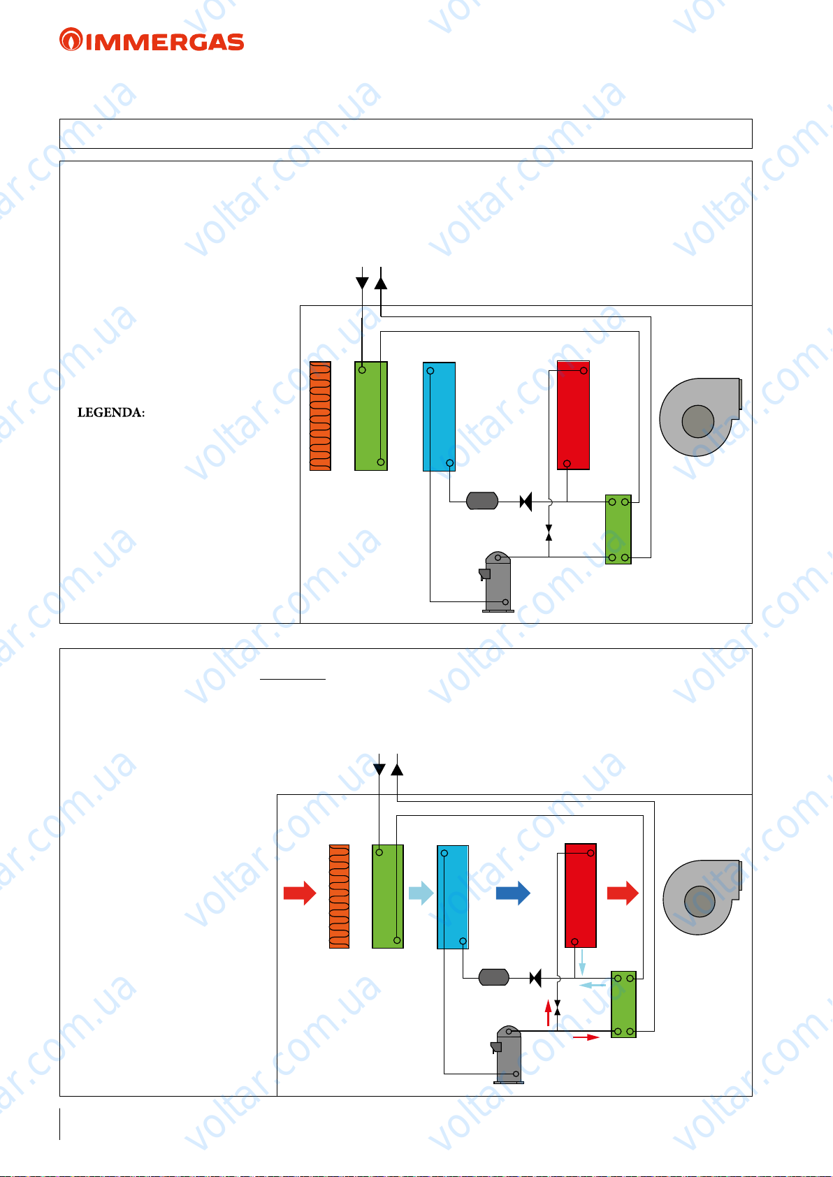
voltar.com.ua
voltar.com.ua
voltar.com.ua
AUDAX TOP ErP and Integrated System
46.2 OPERATING PRINCIPLE
e humid air is taken from the room through the fan (7) and made to pass through the lter (1) and the pre-cooling water
coil (2), where the air itself is cooled and taken to a condition near to the saturation curve. It then passes through the evaporating coil (3) where air is further cooled and dehumidied.
1 - Air lter
2 - Pre-cooling coil
3 - Evaporator
4 - Compressor
5 - Condenser
6 - Post-cooling coil
7 - Fan
8 - rottle valve
9 - Dryer lter
10 - Shut-o valve
voltar.com.ua
3
voltar.com.ua
1 2
voltar.com.ua
5
voltar.com.ua
8
9
10
4
6
voltar.com.ua
7
voltar.com.ua
Dehumidication mode with neutral air
e cooling circuit works by partially condensing in water through the heat exchanger (6) and partially in air through the heat
exchanger (5); accordingly air post-heating is performed and this air is sent into the room in thermically neutral conditions.
voltar.com.ua
voltar.com.ua
1 2
voltar.com.ua
3
5
voltar.com.ua
6
8
9
10
4
voltar.com.ua
7
voltar.com.ua
82
voltar.com.ua
voltar.com.ua
voltar.com.ua
Page 83
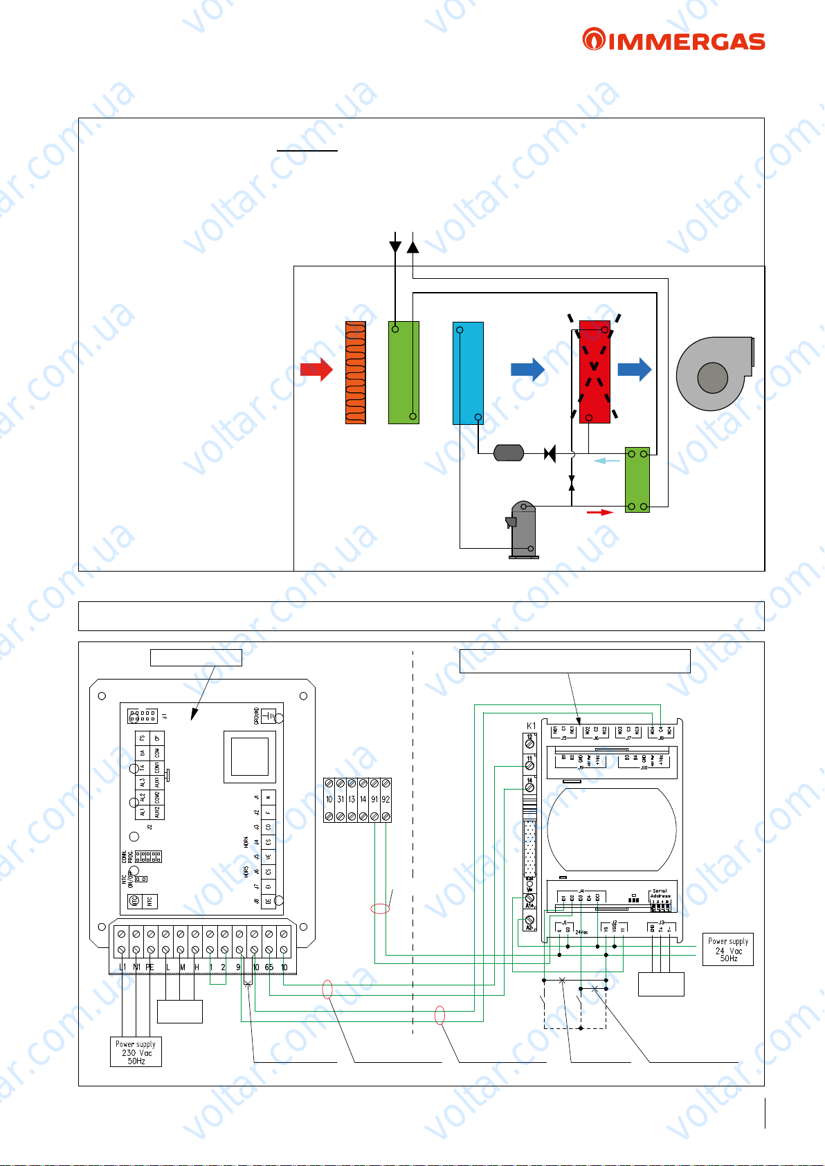
voltar.com.ua
voltar.com.ua
voltar.com.ua
AUDAX TOP ErP and Integrated System
Dehumidication mode with cooled air
In this case, the cooling circuit performs 100% of condensation in water via the heat exchanger (6). e condenser (5) is
cut-o via the valve (10) and the air sent into the room is the same – cooled and dehumidied – at evaporator outlet (3).
voltar.com.ua
1 2
voltar.com.ua
46.3 LAYOUT AND WIRING DIAGRAMS
voltar.com.ua
3
voltar.com.ua
9
voltar.com.ua
5
7
6
8
10
4
voltar.com.ua
Dehumidier Expansion board for zone management
Power supply
voltar.com.ua
voltar.com.ua
Sel. Fan
speed
Remove to connect
the expansion
Enabled in cooled
Alarm signal
air mode
voltar.com.ua
A15
voltar.com.ua
To the System
Manager
Enabled in neutral
air mode
S50S20
Remove to
connect TA
voltar.com.ua
voltar.com.ua
Power supply
Remove to connect
the Humidistat
voltar.com.ua
voltar.com.ua
83
voltar.com.ua
Page 84
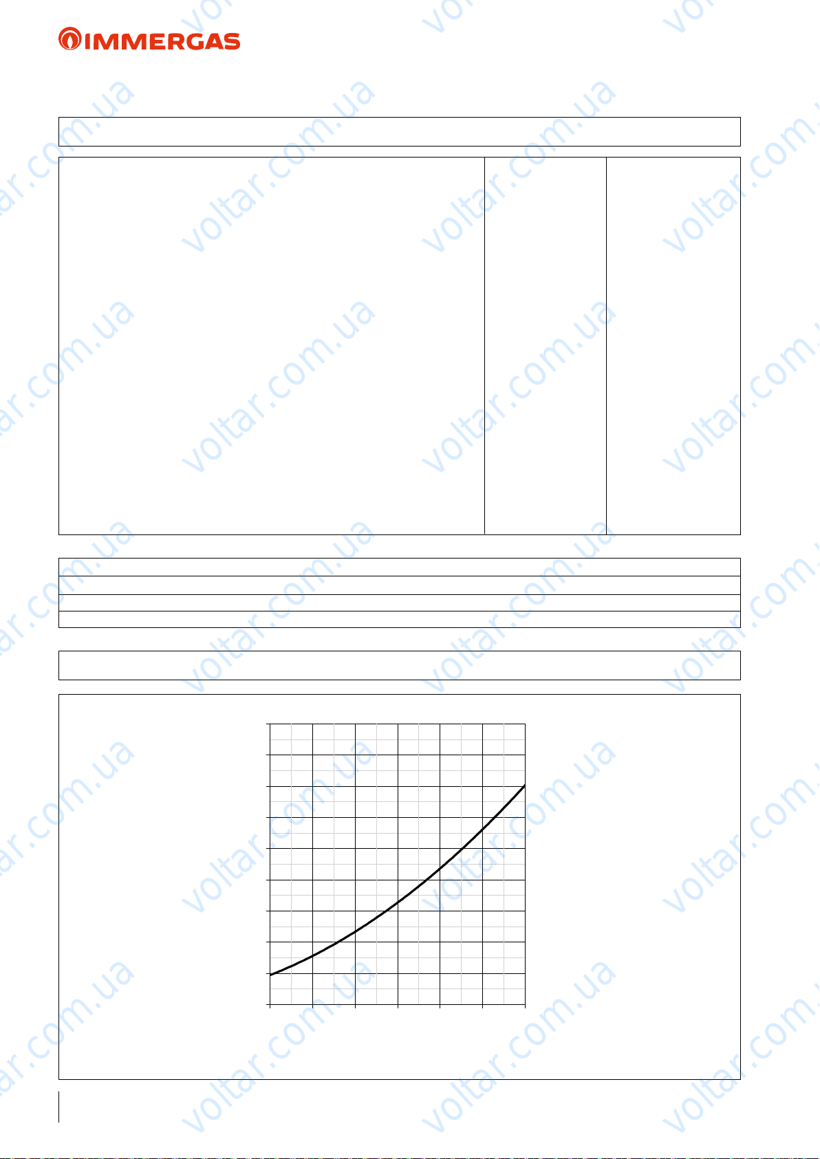
voltar.com.ua
voltar.com.ua
AUDAX TOP ErP and Integrated System
46.4 TECHNICAL DATA
Refrigerant R134a
Humidity removed in neutral air condition
Cooling capacity
Nominal water flow rate l/h 150
Load losses kPa 7.8
Water supply temperature operating field °C 15 - 45
Humidity operating field % 40 - 90
Air flow rate m3/h 250
Fan useful static head (maximum speed) Pa 43
Sound pressure
Sound power dB(A) 43
Absorbed power
Supply voltage V/Ph/Hz 230/1~/50
Maximum absorbed power
Nominal current absorbed
Maximum current absorbed
Hydraulic F-R connections 1/2"F
Weight kg 38
(1)
W 1250
voltar.com.ua
(3)
dB(A) 35
(1)
(2)
W 450
(1)
A 2.5
(2)
voltar.com.ua
A 2.8
(1)
l/24h 20.1
voltar.com.ua
W 340
voltar.com.ua
voltar.com.ua
voltar.com.ua
voltar.com.ua
e data given refer to the following conditions:
1)
Room temperature 26°C; relative humidity 65% with coil inlet water temperature of 15°C.
2)
Room temperature 35°C; relative humidity 80%.
3)
Sound pressure level measured in free eld at 1 m from the machine, in compliance with UNI EN ISO 3746/97
46.5 LOAD LOSS OF THE HYDRAULIC CIRCUIT
voltar.com.ua
45
40
35
30
25
20
voltar.com.ua
15
Head losses (kPa)
10
voltar.com.ua
voltar.com.ua
voltar.com.ua
voltar.com.ua
84
5
0
100 150 200 250 300 350 400
voltar.com.ua
Flow rate l/h
voltar.com.ua
voltar.com.ua
Page 85
voltar.com.ua
voltar.com.ua
voltar.com.ua
AUDAX TOP ErP and Integrated System
47 INTRODUCTION WITH COMMENTARY TO INTEGRATED SYSTEMS: MAIN APPLICATIONS
4848.1 Diagram with AUDAX TOP ErP and system distribution kit + DHW solar heating
System manager
Description of winter functioning:
- Central heating mode active 1 or more temperature/humidity sensors activate winter mode consent; the System Manager,
according to the outdoor temperature detected and system's climatic curve and room temperature set for the various zones, activates
AUDAX TOP ErP and (if COP is too low or if the temperature is not reached within the set time), the system's electrical resistance
(via parameters that can be set with alternative or simultaneous operation).
- Domestic hot water mode The System Manager, in addition operating the solar system, continuously monitors the set DHW
temperature (probe located in the top part of the storage tank), enabling AUDAX TOP ErP and (if necessary) the electric resistance
of the storage tank.
The System manager will activate the integrative electric resistance of the storage tank only on request of the anti-legionella function
and on reaching temperatures over 50 °C or if time required for making operational that is too long is considered.
voltar.com.ua
voltar.com.ua
voltar.com.ua
Description of winter functioning:
- Central heating mode active Control Panel (standard) activates AUDAX TOP ErP in winter mode.
Two dierent management options are possible to activate integrative electrical resistance, which are based on the outdoor temperature:
1) Switching the heat pump o and activating the auxiliary source (electrical resistance), if the outdoor temperature is below
2) Both the heat pump and electrical resistance are simultaneously activated if the outdoor temperature is between the 2 values
- DHW mode when there is request for DHW, the system integrative resistance switches o and the 3-way valves divert onto
the storage tank. AUDAX TOP ErP goes to the max temp. of 60 °C (compatible with the operating limits). e domestic hot
water temperature is set on the solar control unit; if the set "setting" is greater than 50 °C, AUDAX TOP ErP heats the domestic
hot water to 50 °C, the integrative resistance then switches on and the heat pump switches o.
Description of winter functioning:
- Central heating mode active 1 or more zone Controls activate winter mode consent; the system Manager, according to the
outdoor temperature detected and the room temperature set above the pre-set climatic curve, activates AUDAX TOP ErP or the
boiler according to the COP calculated (if > the minimum economical convenience value - use of AUDAX TOP ErP is approved),
or according to Tminimum integration (cut o) set in the System Manager.
Remember that also times for making the system operational can vary the boiler insertion mode.
- Domestic hot water mode this system was designed to privilege DHW operation of the boiler only, obviously in addition to the
solar heating system (governed by the System Manager). During the summer cooling mode, the inversion of the AUDAX TOP ErP
functioning cycle is also prevented (from chiller to heat pump).
4949.1 Diagram with AUDAX TOP ErP + Control panel (standard for room control) + DHW solar pack
the value set in the parameter (example - 15 °C);
set in the parameter (e.g. between 0 °C and - 15 °C).
5050.1 Diagram with AUDAX TOP ErP (air conditioning only) + boiler Plus + system distribution kit
voltar.com.ua
voltar.com.ua
+ solar heating for DHW + System Manager
voltar.com.ua
voltar.com.ua
voltar.com.ua
voltar.com.ua
voltar.com.ua
voltar.com.ua
voltar.com.ua
voltar.com.ua
voltar.com.ua
85
voltar.com.ua
Page 86
voltar.com.ua
voltar.com.ua
voltar.com.ua
AUDAX TOP ErP and Integrated System
5151.1 Diagram with AUDAX TOP ErP + boiler + 1 high temperature zone and system distribution
kit + solar heating for DHW + System Manager
Description of winter functioning:
- Central heating mode active with respect to the previous layout, this system lets us have a simultaneous functioning variable
of 1 high temperature zone and 2 low temperature zones. Substantially, we will have 3 cases:
1) Boiler serving a high temperature zone and AUDAX TOP ErP serving a low temperature zone.
2) Boiler serving a high temperature zone and low temperature zone.
3) AUDAX TOP ErP serving low temperature zones only.
ese functioning modes are managed via appropriate positioning of the 2 x 2-way solenoid valves.
- DHW mode if the Manager is connected to a boiler on the external probe clamps (refer to the list of provided models on page
71), the Heat Pump is activated if COP > COPmin / Toutdoor > Tminimum integration. At this point, if the set DHW is < 50
°C, AUDAX TOP ErP is active; however, if the set DHW is > 50 °C, AUDAX TOP ErP will heat water until it reaches 50 °C and
then lets the boiler complete heating until the set value.
5252.1 Diagram with AUDAX TOP ErP + boiler Plus + system distribution kit
voltar.com.ua
+ DHW storage tank+ System manager
voltar.com.ua
voltar.com.ua
Description of winter functioning:
- Central heating mode active the Control Panel and temperature/humidity sensor manage air conditioning of the 2 mac-
ro-environments. Based on the outdoor temperature and room temperature detected and according to the set climatic curve, the
System Manager activates AUDAX TOP ErP or the boiler COP calculated (if > minimum economical convenience value, use of
AUDAX TOP ErP is appoved), or according to Tminimum integration (cut o) set in the System Manager.
- DHW mode with this integrated system, the only source of renewable energy for DHW production is guaranteed from the heat
pump. By means of the 3-way solenoid valve commutation between the system and storage tank, AUDAX TOP ErP is connected
to the lower coil in the storage tank, thus guaranteeing central heating of a large amount of DHW (e.g: approximately 40 °C - in
both winter and summer). Integration is guaranteed by the boiler, which is connected to both coils independently.
5353.1 Diagram with AUDAX TOP ErP (Summer/Winter air conditioning only) + boiler with
storage tank + DHW solar heating and separate central heating and cooling system - System Manager
Description of winter functioning:
- Central heating mode active 1 or more room thermostats, which act on the thermoelectric heads of the radiant system, enable
a request in winter mode to the System Manager; this, in turn, based on the various parameters it is reading at that moment, enables
AUDAX TOP ErP or the boiler if the calculated COP is lower than the minimum value of economical convenience.
rough expansion "5", the System Manager controls the diverter valves, which commute with mode change (central heating/cooling).
Description of summer functioning:
- Cooling mode active 1 or more room thermostats, by acting on the fan-coils, enable a request in summer mode to the System
Manager, which, in turn enables the heat pump.
voltar.com.ua
voltar.com.ua
voltar.com.ua
voltar.com.ua
voltar.com.ua
voltar.com.ua
- Domestic hot water mode In this specific case, domestic hot water production is managed by the boiler; the solar heating system,
which is connected directly to the boiler, is also managed by the electronics of HERCULES SOLAR 200 CONDENSING ErP.
NOTE: in this diagram, the Control Panel (standard with AUDAX TOP ErP) is not used.
86
voltar.com.ua
voltar.com.ua
voltar.com.ua
voltar.com.ua
voltar.com.ua
voltar.com.ua
Page 87

voltar.com.ua
voltar.com.ua
voltar.com.ua
AUDAX TOP ErP and Integrated System
5454.1 Diagram with AUDAX TOP ErP in cascade (air conditioning only) + high-power boiler + thermal
ywheel and mixed zone + solar heating for D.H.W. production + System manager
Description of winter and summer operation:
- Central heating/cooling mode active 1 or more room thermostats, by acting on the apartment counters, enable a request to
the expansion board that manages the upright column (mixed zone); the expansion board, in turn, sends the signal to the System
Manager. Through a second expansion and an adjustable thermostat built into the storage tank, the Manager controls the temperature of the thermal flywheel in hot and cold. In this specific case, the temperature of the thermal flywheel, controlled by the
thermostat, must have a greater offset (T. higher by 1-2 °C) than the relaunch mixed zone in winter, and a lower offset (T. lower
by 1-2 °C) than the relaunch mixed zone in summer.
Activation of the system (AUDAX TOP ErP rather than a gas generator) is, by standard, delegated by request from the thermostats
and then the System Manager, which assesses the economic convenience or compares Toutdoor with Tminimum integration (cut o).
- Domestic hot water mode this system was designed to privilege DHW operation of the boiler only, obviously in addition to
the solar heating system (governed by the System Manager along with the recirculation pump, through expansion "5").
NOTE: in this diagram, the Control Panel (standard with AUDAX TOP ErP) is not used.
voltar.com.ua
voltar.com.ua
voltar.com.ua
5555.1 Diagram with AUDAX TOP ErP + boiler + system distribution kit + solar heating for
Description of winter and summer operation:
voltar.com.ua
- Central heating/cooling mode attiva request from a room activates a central heating/cooling request via expansion in the
hydraulic distribution kit, which, in turn, is connected via BUS to the system Manager. In the event of a cooling request via the
diverter valve, the heat pump sends cooling fluid directly to the distribution kit. However, if central heating request is made, the
distribution kit draws hot fluid from the combined storage tank.
rough expansion "4" the System Manager also governs the 2 3-way valves that direct the hot uid coming from the heat pump
or from the boiler towards the storage tank, based on the requests from probes "B13" and "B2".
- DHW mode the system Manager controls the DHW from probe B2; the set-point to reach in B2 is connected to the DHW
temperature requested + 10 °C. e system Manager activates AUDAX TOP ErP to bring the temperature in B2 to 50 °C, above
which the integrative generator will be activated (in this case, the boiler).
voltar.com.ua
DHW production and C.H. + System manager
voltar.com.ua
voltar.com.ua
voltar.com.ua
voltar.com.ua
voltar.com.ua
voltar.com.ua
voltar.com.ua
voltar.com.ua
voltar.com.ua
87
voltar.com.ua
Page 88
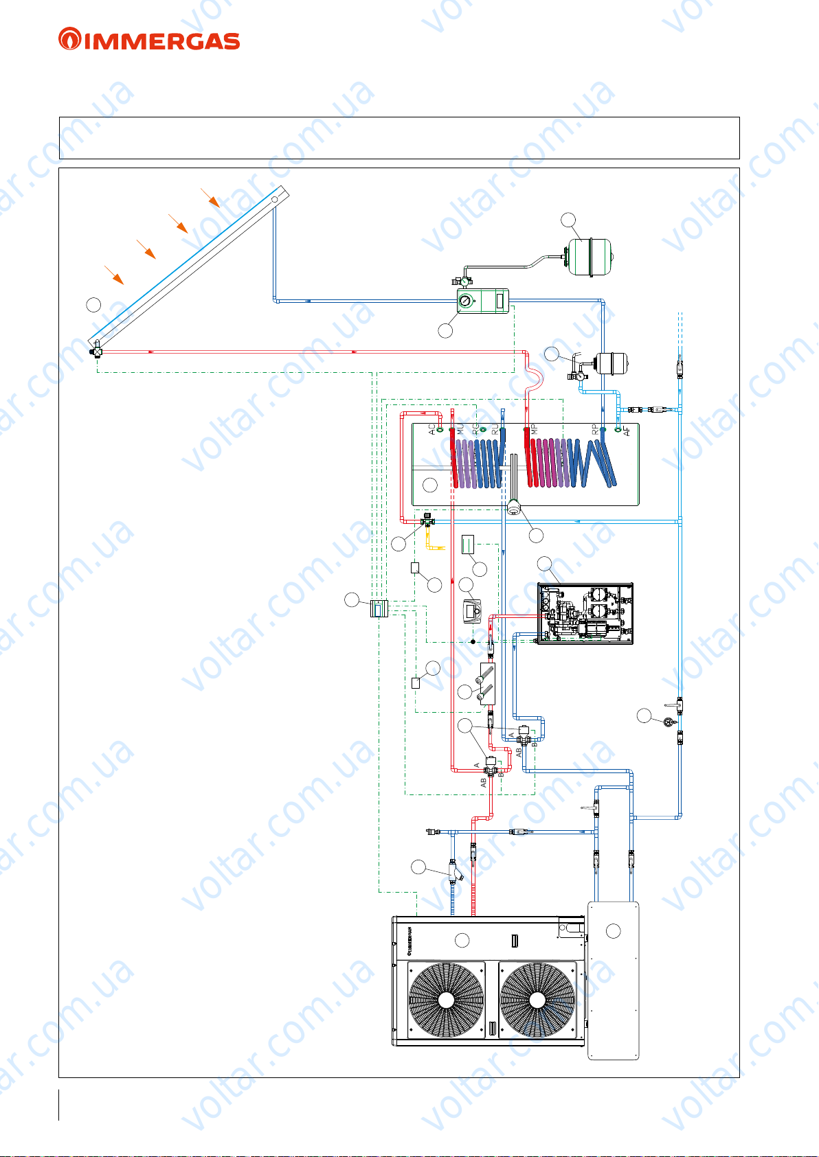
AB
B
A
AB
B
A
voltar.com.ua
voltar.com.ua
AUDAX TOP ErP and Integrated System
48 HYDRAULIC DIAGRAM: AUDAX TOP ErP and 2 low temperature zones
+ SOLAR HEATING for DHW + SYSTEM MANAGER
6
voltar.com.ua
voltar.com.ua
3
voltar.com.ua
12
voltar.com.ua
5
7
voltar.com.ua
4
11
13
10
18
9
8
voltar.com.ua
voltar.com.ua
KEY:
1 - AUDAX TOP 16 ErP
2 - Integrative resistance for heating system kit (selectable powers: 2 - 4 - 6 kW)
3 - M/XL CP4 solar manifold
4 - Double coil storage tank unit
5 - Solar ErP circulation unit with safety valve
voltar.com.ua
voltar.com.ua
6 - Solar expansion vessel
7 - Expansion valve and safety valve for DHW
8 - 2 mixed zones kit (including expansion boards for zone management)
9 - Integrative resistance for 2 or 5 kW storage tanks
10 - Temperature/humidity sensor
11 - DHW thermostatic mixer
12 - System Manager
13 - DHW resistance enabling relay (EMR 12 Vdc)
14 - 3-way diverter kit
15 - Heating system resistance enabling relay (SSR 6 Vdc)
16 - Standard "Y" lter for AUDAX TOP ErP
17 - Inertial storage tank
18 - Control Panel (standard)
19 - System pressure gauge (to provide)
15
2
voltar.com.ua
14
16
voltar.com.ua
1
17
voltar.com.ua
19
voltar.com.ua
NOTE: this diagram is an example. It is also required to convey the heat pump's condensate drain.
In order to guarantee proper Heat Pump operation (also with antifreeze), each system must consider inserting a bypass to guarantee a minimum ow rate of 420 l/h. In this diagram, the bypass is already
installed in the zones kit (8).
88
voltar.com.ua
voltar.com.ua
voltar.com.ua
Page 89
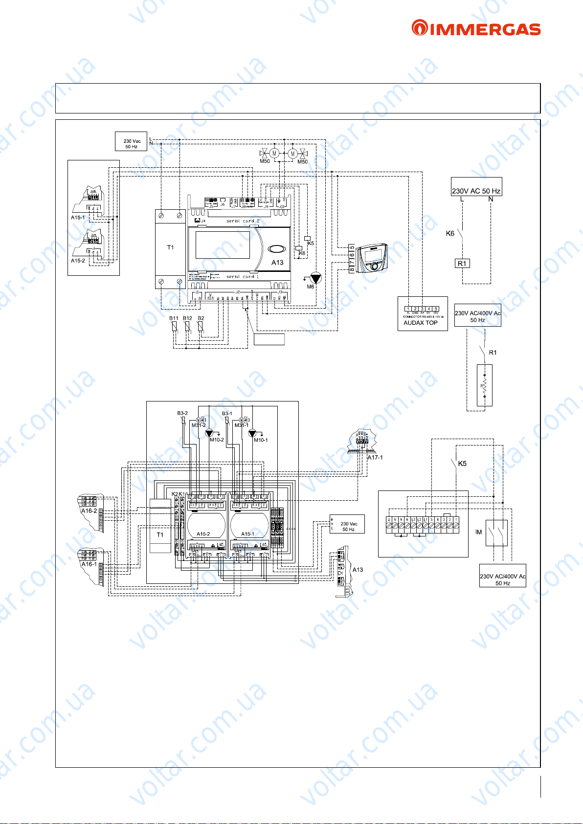
DEHUMIDIFIER KIT
voltar.com.ua
voltar.com.ua
AUDAX TOP ErP and Integrated System
48.1 WIRING DIAGRAM: AUDAX TOP ErP and 2 low temperature zones
+ SOLAR HEATING for DHW + SYSTEM MANAGER
Power supply
voltar.com.ua
ZONE KIT
voltar.com.ua
voltar.com.ua
MIXED ZONES 2 KIT
Black
Black
Red
Black
Grey
Black
Boiler alarm
input
Black
Black
OrangeOrange
Red
Black
Black
Black
Grey
voltar.com.ua
Control Panel
Power supply
Power supply
voltar.com.ua
D.H.W. integrative
electric resistance kit
TEMP./HUMIDITY
SENSOR KIT
voltar.com.ua
voltar.com.ua
voltar.com.ua
DEHUMIDIFIER KIT
KEY:
A13 - System Manager
A15-1 - L.T. zone expansion 1
A15-2 - L.T. zone expansion 2
B2 - Storage tank upper part temp. probe (NTC)
B11 - Solar manifold probe (PT1000)
B12 - Storage tank lower part temp. probe (NTC)
K5 - System integrative resistance enabling relay
(abbreviation SSR 6 Vdc code: 3.023946)
K6 - DHW integrative resistance enabling relay
(abbreviation EMR 12 Vdc code: 3.023945)
M6 - Solar ErP circulation group
M50 - DHW priority 3-way valve
T1 - 24 Vac transformer (not supplied with the
system Manager - standard with the distribution kit)
voltar.com.ua
ZONE 2 ZONE 1
Orange
Grey
Purple
Light Blue
Orange
Grey
Green
Brown
White
Brown
voltar.com.ua
Power supply
Brown
Blue
Black
Red
A16-1 - Zone 1 dehumidier (possible)
A16-1 - Zone 2 dehumidier (possible)
A17-1 - Zone 1 temperature/humidity sensor
B3-1 - Zone 1 ow temperature probe
voltar.com.ua
B3-2 - Zone 2 ow temperature probe
K2 - Zone 1 cooling enabling
K2 - Zone 2 cooling enabling
R1 - DHW resistance enabling relay
M10-1 - Zone 1 pump
M10-2 - Zone 2 pump
M31-1 - Mixing zone 1
M31-2 - Zone 2 mixer
NOTE: with this setting, the Control Panel (standard supply with
AUDAX TOP ErP) is used as a Room Probe in the mixed zone 2.
C.H. integrative electric
resistance kit
voltar.com.ua
Power supply
voltar.com.ua
voltar.com.ua
voltar.com.ua
89
voltar.com.ua
Page 90
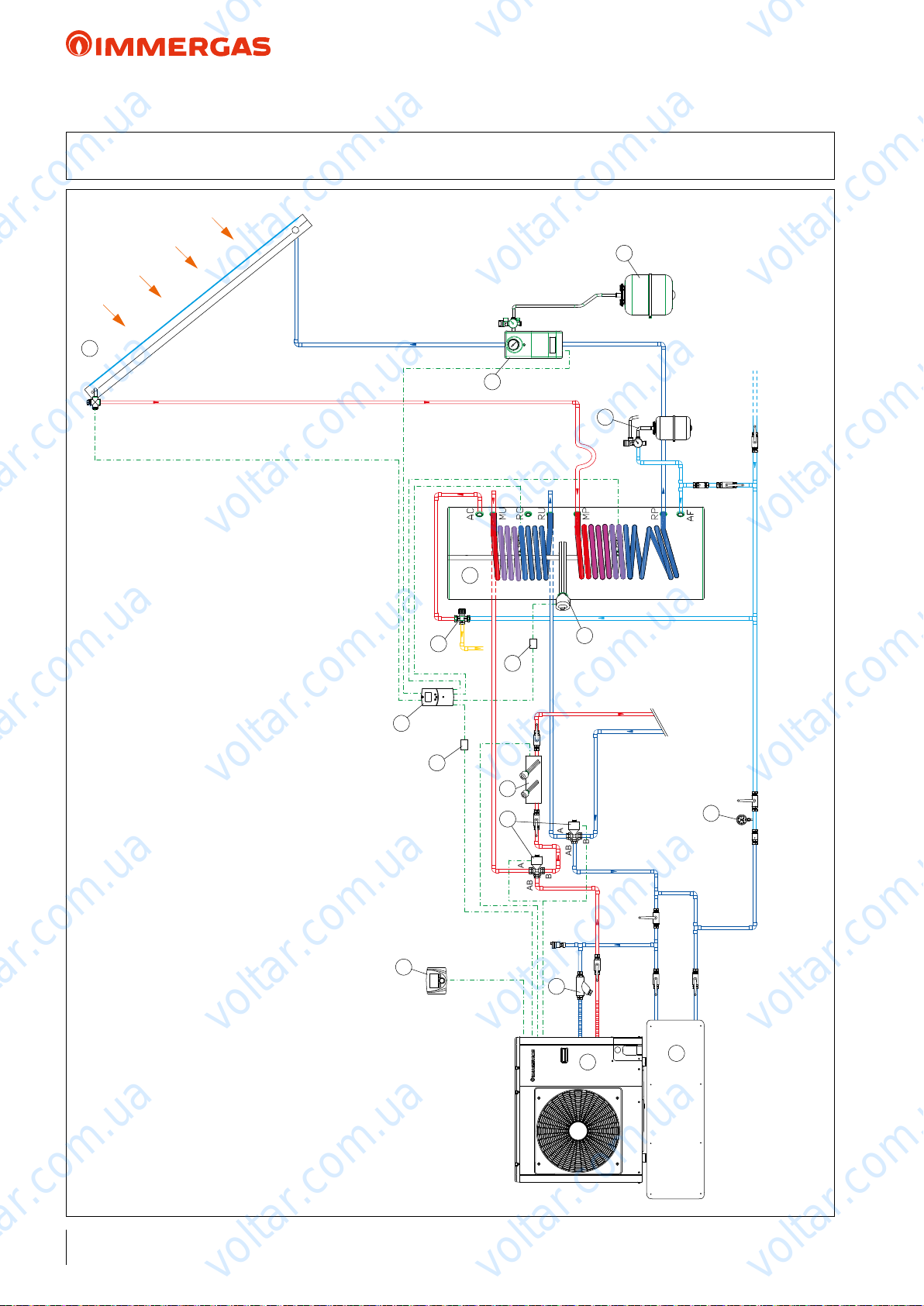
AB
B
A
AB
B
A
voltar.com.ua
voltar.com.ua
AUDAX TOP ErP and Integrated System
49 HYDRAULIC DIAGRAM: AUDAX TOP ErP + CONTROL PANEL STANDARD
FOR ROOM CONTROL + SOLAR PACK for DHW
6
voltar.com.ua
voltar.com.ua
3
voltar.com.ua
10
11
voltar.com.ua
5
7
voltar.com.ua
4
8
9
voltar.com.ua
voltar.com.ua
17
voltar.com.ua
13
voltar.com.ua
KEY:
1 - AUDAX TOP 6/8 ErP
2 - Integrative resistance for heating system kit (selectable powers: 2 - 4 - 6 kW)
3 - M/XL CP4 solar manifold
4 - Double coil storage tank unit
5 - Solar ErP circulation unit with safety valve
6 - Solar expansion vessel
7 - Expansion valve and safety valve for DHW
8 - Integrative resistance for 2 or 5 kW storage tanks
9 - DHW resistance enabling relay
10 - DHW thermostatic mixer
11 - LCD PICTO solar control unit
12 - 3-way diverter kit
13 - Control Panel (standard)
14 - Standard "Y" lter for AUDAX TOP ErP
15 - Inertial storage tank
16 - System pressure gauge (to provide)
17 - DHW request relay active (not included)
voltar.com.ua
2
12
14
16
voltar.com.ua
1
15
voltar.com.ua
voltar.com.ua
NOTE: this diagram is an example. It is also required to convey the heat pump's condensate drain.
In order to guarantee proper Heat Pump operation (also with antifreeze), each system must consider inserting a bypass to guarantee a minimum ow rate of 420 l/h.
90
voltar.com.ua
voltar.com.ua
voltar.com.ua
Page 91
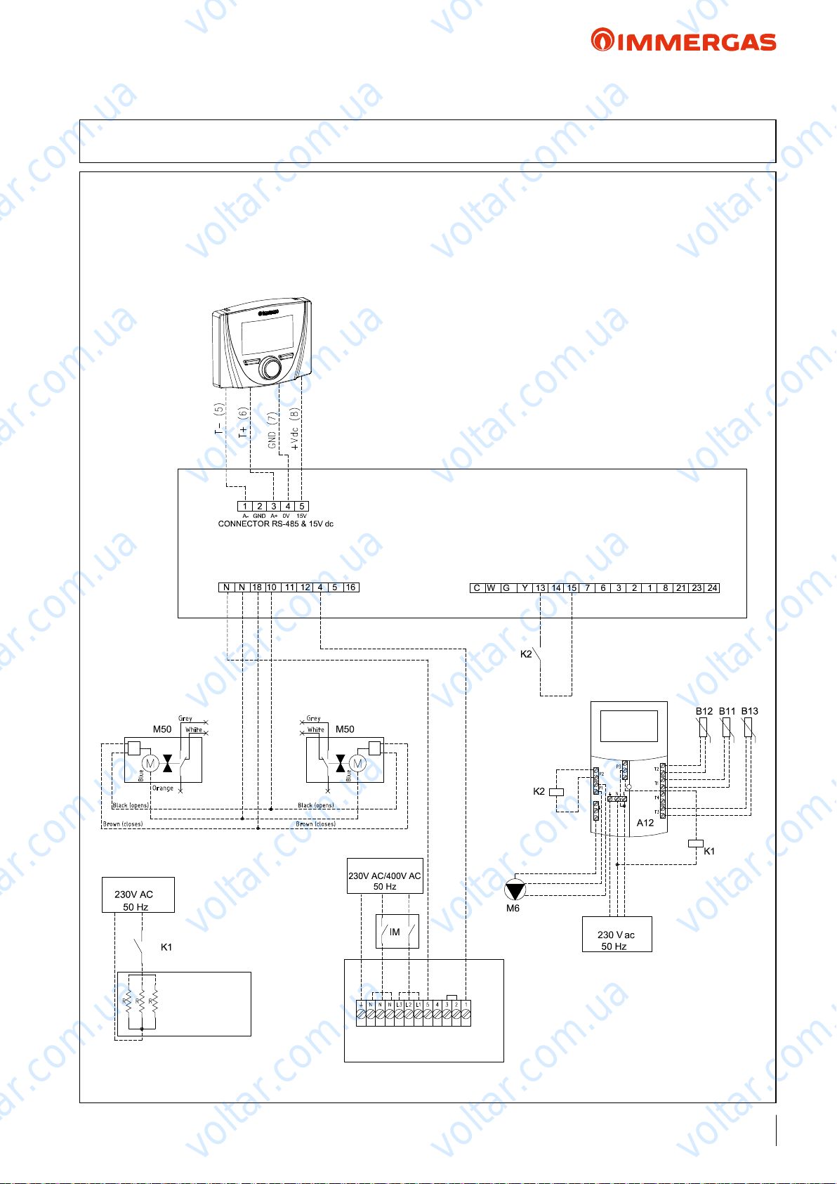
voltar.com.ua
voltar.com.ua
AUDAX TOP ErP and Integrated System
49.1 WIRING DIAGRAM: AUDAX TOP ErP + CONTROL PANEL STANDARD
FOR ROOM CONTROL + SOLAR PACK for DHW
KEY:
A12 - LCD Picto solar control unit (set SYST. 5)
voltar.com.ua
Control Panel
B12 - Storage tank lower part temp. probe (NTC)
voltar.com.ua
B11 - Solar manifold probe (PT1000)
B13 - Storage tank upper part temp. probe (NTC)
IM - Circuit breaker switch
K1 - Storage tank resistance voltage supply relay (not included)
K2 - DHW request relay active (not included)
M6 - Solar ErP circulation group
M50 - DHW priority 3-way diverter valve
NOTE: with this setting, the Control Panel (standard supply with
AUDAX TOP
ErP) is used as a Room Probe system.
voltar.com.ua
voltar.com.ua
Blue
Black (opens)
Brown (closes)
Power supply
Orange
voltar.com.ua
voltar.com.ua
Grey
White
Grey
White
Blue
Black (opens)
Brown (closes)
Power supply
voltar.com.ua
AUDAX TOP ErP P.C.B.
voltar.com.ua
voltar.com.ua
voltar.com.ua
voltar.com.ua
D.H.W. integrative
electric resistance kit
C.H. integrative electric
resistance kit
voltar.com.ua
voltar.com.ua
Power supply
voltar.com.ua
voltar.com.ua
91
voltar.com.ua
Page 92
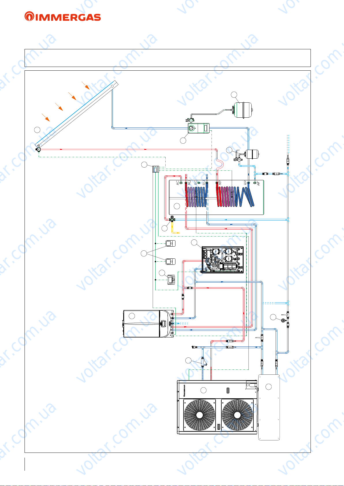
voltar.com.ua
voltar.com.ua
voltar.com.ua
AUDAX TOP ErP and Integrated System
50 HYDRAULIC DIAGRAM: AUDAX TOP ErP air conditioning only) + BOILER PLUS and 2
low temperature zones and 1 direct ZONE + solar heating for DHW + SYSTEM MANAGER
6
voltar.com.ua
3
10
voltar.com.ua
14
11
voltar.com.ua
5
7
voltar.com.ua
4
9
8
voltar.com.ua
voltar.com.ua
voltar.com.ua
2
voltar.com.ua
management)
KEY:
1 - AUDAX TOP 12 ErP
2 - VICTRIX SUPERIOR 32 PLUS ErP
3 - XL CP4 solar manifold
4 - Double coil storage tank unit
5 - Solar ErP circulation unit with safety valve
6 - Solar expansion vessel
7 - Expansion valve and safety valve for DHW
8 - 2 mixed zones and 1 direct zone kit (including expansion boards for zone
9 - DHW thermostatic mixer
10 - System Manager
11 - Control Panel (standard)
12 - Standard "Y" lter for AUDAX TOP ErP
13 - Inertial storage tank
14 - Remote zone control
15 - System pressure gauge (to provide)
voltar.com.ua
15
12
voltar.com.ua
1
13
voltar.com.ua
voltar.com.ua
NOTE: this diagram is an example. It is also required to convey the condensate drain of the heat pump and boiler.
In order to guarantee proper Heat Pump operation (also with antifreeze), each system must consider inserting a bypass to guarantee a minimum ow rate of42 l/h. In this diagram, the bypass is already
installed in the zones kit (8).
92
voltar.com.ua
voltar.com.ua
voltar.com.ua
Page 93
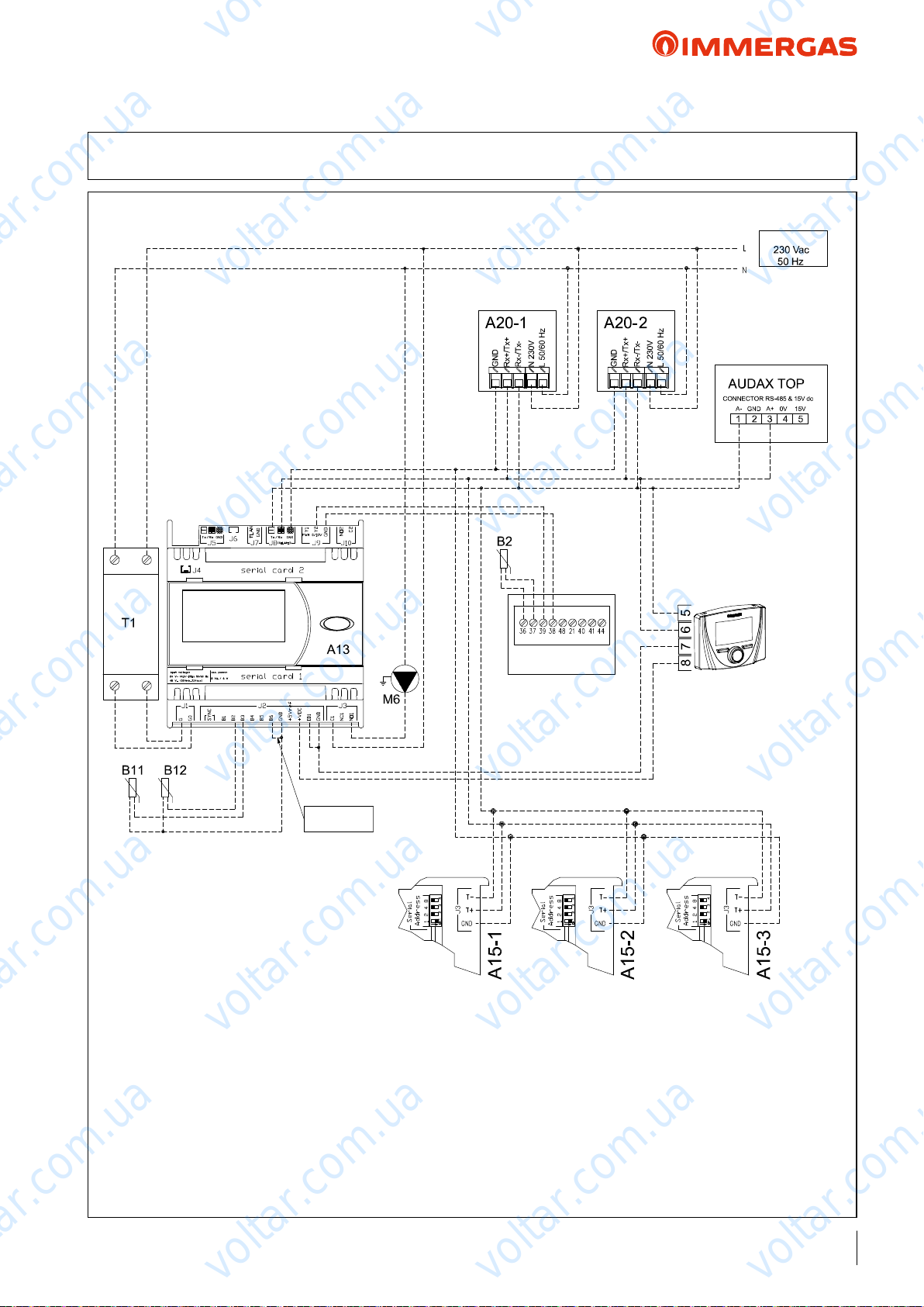
voltar.com.ua
voltar.com.ua
voltar.com.ua
AUDAX TOP ErP and Integrated System
50.1 WIRING DIAGRAM: AUDAX TOP ErP air conditioning only) + BOILER PLUS and 2
low temperature zones and 1 direct ZONE + solar heating for DHW + SYSTEM MANAGER
Power supply
voltar.com.ua
voltar.com.ua
voltar.com.ua
NOTE: with this setting, the
voltar.com.ua
BOILER
Control Panel (standard supply
with AUDAX TOP ErP) is used
as a Room Probe in the direct
zone 3.
Control Panel
voltar.com.ua
voltar.com.ua
voltar.com.ua
Boiler alarm
input
KEY:
A13 - System Manager
A20-1 - Zone 1 L.T. remote control
A20-2 - Zone 2 L.T. remote control
A15-1 - L.T. zone expansion 1
A15-2 - L.T. zone expansion 2
A15-3 - Direct L.T. zone 3 expansion
B2 - Storage tank upper part temp. probe (NTC)
B11 - Solar manifold probe (PT1000)
B12 - Storage tank lower part temp. probe (NTC)
M6 - Solar ErP circulation group
T1 - 24 Vac transformer (not supplied with the
voltar.com.ua
System Manager)
voltar.com.ua
voltar.com.ua
voltar.com.ua
voltar.com.ua
voltar.com.ua
voltar.com.ua
93
voltar.com.ua
Page 94
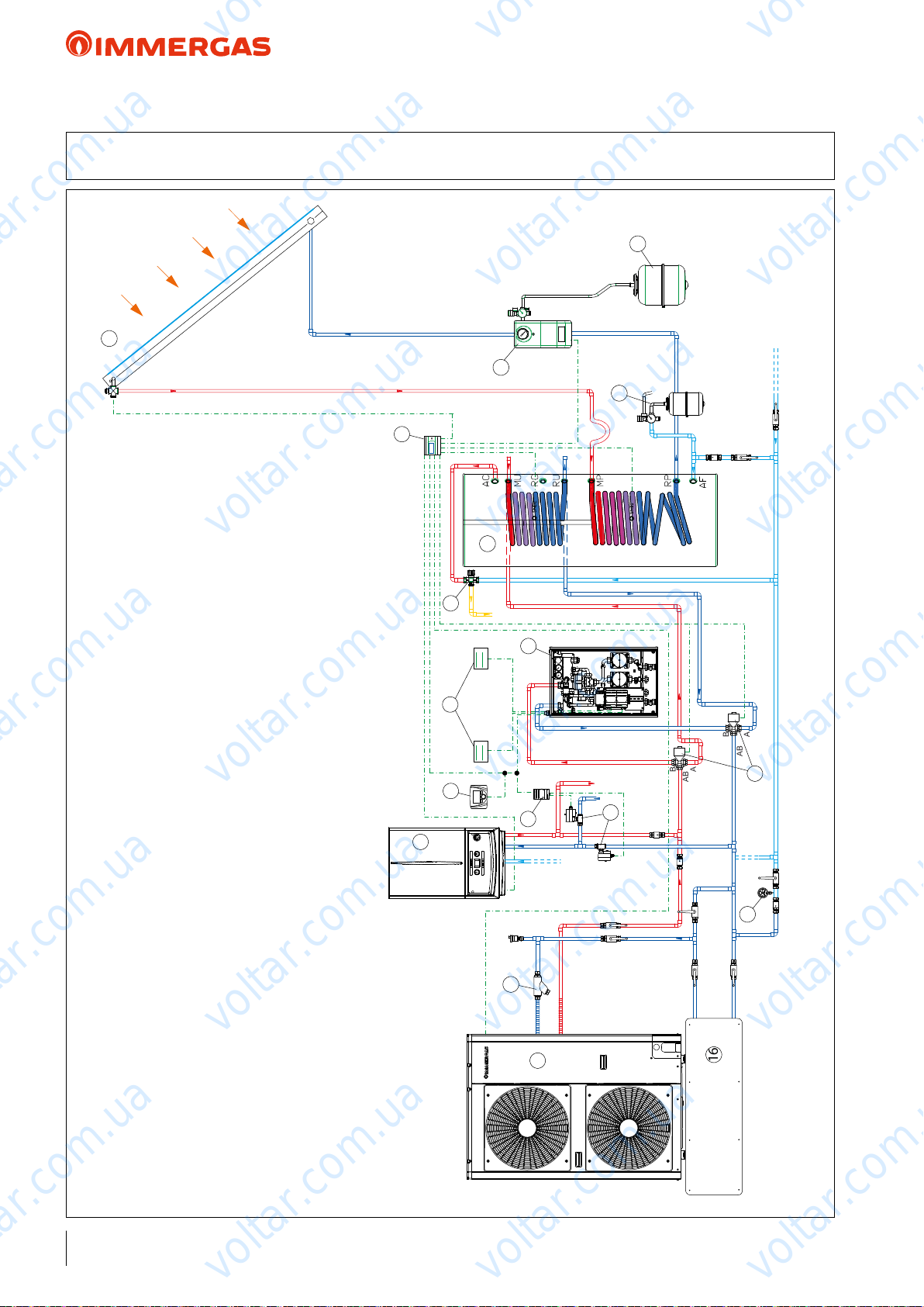
AB
B
A
AB
B
A
16
voltar.com.ua
voltar.com.ua
voltar.com.ua
AUDAX TOP ErP and Integrated System
51 HYDRAULIC DIAGRAM: AUDAX TOP ErP + BOILER with 1 high temperature zone + 2
low temperature zones + SOLAR HEATING for D.H.W. PRODUCTION + SYSTEM MANAGER
6
voltar.com.ua
3
10
voltar.com.ua
voltar.com.ua
5
7
voltar.com.ua
4
9
8
11
voltar.com.ua
voltar.com.ua
voltar.com.ua
2
voltar.com.ua
KEY:
1 - AUDAX TOP 12 ErP
2 - VICTRIX TT / MAIOR TT / kW TT PLUS / MAIOR TT PLUS
3 - M/XL CP4 solar manifold
4 - Double coil storage tank unit
5 - Solar ErP circulation unit with safety valve
6 - Solar expansion vessel
7 - Expansion valve and safety valve for DHW
8 - 2 mixed zones kit (including expansion boards for zone management)
9 - DHW thermostatic mixer
10 - System Manager
11 - Temperature/humidity sensor
12 - Control Panel (standard)
13 - Expansion panel with address 4 to manage the high temperature zone
14 - Zone solenoid valve
15 - 3-way diverter kit
16 - Inertial storage tank
17 - Standard "Y" lter for AUDAX TOP ErP
18 - System pressure gauge (to provide)
voltar.com.ua
12
13
17
14
voltar.com.ua
1
15
voltar.com.ua
18
voltar.com.ua
NOTE: this diagram is an example. It is also required to convey the condensate drain of the heat pump and boiler.
In order to guarantee proper Heat Pump operation (also with antifreeze), each system must consider inserting a bypass to guarantee a minimum ow rate of42 l/h. In this diagram, the bypass is already
installed in the zones kit (8).
94
voltar.com.ua
voltar.com.ua
voltar.com.ua
Page 95
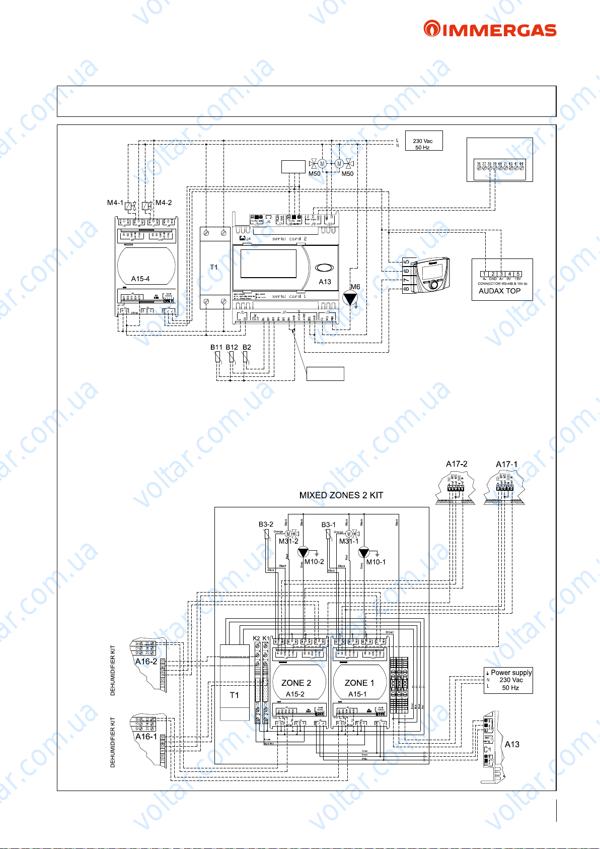
voltar.com.ua
voltar.com.ua
voltar.com.ua
AUDAX TOP ErP and Integrated System
51.1 WIRING DIAGRAM: AUDAX TOP ErP + BOILER with 1 high temperature zone +
2 low temperature zones + SOLAR HEATING for DHW + SYSTEM MANAGER
Power supply
BOILER
TO ZONE
EXPANSION
voltar.com.ua
H.T. ZONE
voltar.com.ua
KEY:
A13 - System Manager
A15-4 - H.T. zone expansion
B2 - Storage tank upper part temp. probe (NTC)
B11 - Solar manifold probe (PT1000)
B12 - Storage tank lower part temp. probe (NTC)
M4-1 - H.T. zone 2-way valve
M4-2 - L.T. zone 2-way valve + DHW
M6 - Solar ErP circulation group
M50 - DHW priority 3-way valve
T1 - 24 Vac transformer (not supplied with the
system Manager - standard with the distri-
A15-1 - L.T. zone expansion 1
A15-2 - L.T. zone expansion 2
A16-1 - Zone 1 dehumidier (possible)
A16-1 - Zone 2 dehumidier (possible)
A17-1 - Zone 1 temp/humid sensor
A17-2 - Zone 2 temp/humid sensor
B3-1 - Zone 1 ow temp. probe
B3-2 - Zone 2 ow temp. probe
K1 - Zone 1 cooling enabling
K2 - Zone 2 cooling enabling
M10-1 - Zone 1 pump
M10-2 - Zone 2 pump
M31-1 - Mixing zone 1
M31-2 - Zone 2 mixer
bution kit)
voltar.com.ua
voltar.com.ua
Control Panel
NOTE: with this setting, the Control Panel
(standard supply with AUDAX TOP ErP) is
voltar.com.ua
Boiler alarm
input
used to manage the high temperature zone.
voltar.com.ua
voltar.com.ua
voltar.com.ua
voltar.com.ua
voltar.com.ua
voltar.com.ua
voltar.com.ua
voltar.com.ua
voltar.com.ua
95
voltar.com.ua
Page 96
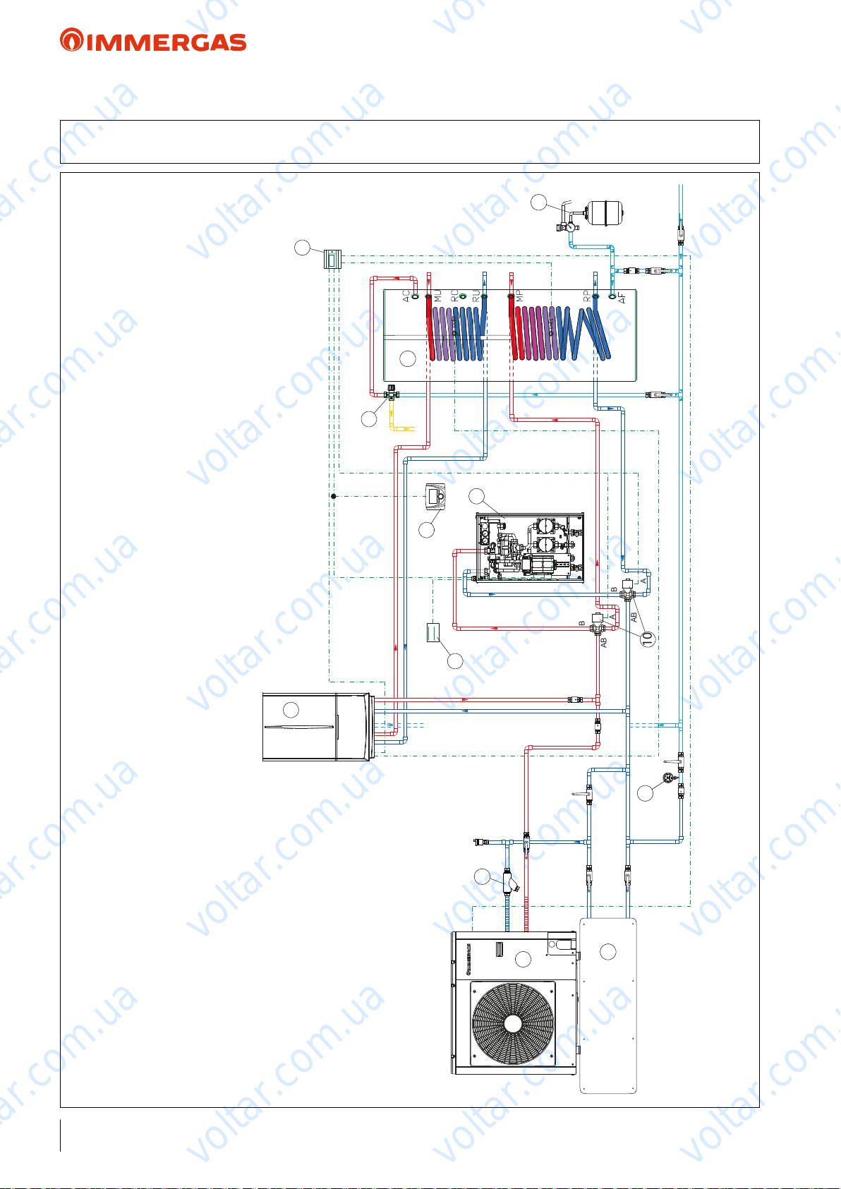
10
AB
B
A
AB
B
A
voltar.com.ua
voltar.com.ua
voltar.com.ua
AUDAX TOP ErP and Integrated System
52 HYDRAULIC DIAGRAM: AUDAX TOP ErP + BOILER PLUS and 2 low temperature zones
+ STORAGE TANK UNIT for D.H.W. PRODUCTION + SYSTEM MANAGER
5
voltar.com.ua
3
4
6
voltar.com.ua
8
voltar.com.ua
voltar.com.ua
7
voltar.com.ua
voltar.com.ua
voltar.com.ua
2
voltar.com.ua
9
voltar.com.ua
13
12
voltar.com.ua
1
11
voltar.com.ua
voltar.com.ua
KEY:
1 - AUDAX TOP 6-8 ErP
2 - VICTRIX kW TT PLUS / MAIOR TT PLUS
3 - System Manager
4 - Double coil storage tank unit
5 - Expansion valve and safety valve for DHW
6 - DHW thermostatic mixer
7 - 2 mixed zones kit (including expansion boards for zone management)
8 - Control Panel (standard)
9 - Temperature/humidity sensor
10 - 3-way diverter kit
11 - Inertial storage tank
12 - Standard "Y" lter for AUDAX TOP ErP
13 - System pressure gauge (to provide)
96
voltar.com.ua
voltar.com.ua
NOTE: this diagram is an example. It is also required to convey the condensate drain of the heat pump and boiler.
In order to guarantee proper Heat Pump operation (also with antifreeze), each system must consider inserting a bypass to guarantee a minimum ow rate of 420 l/h. In this diagram, the bypass is already
installed in the zones kit (7).
voltar.com.ua
Page 97
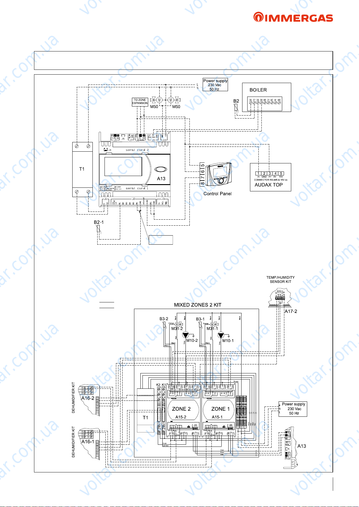
Boiler alarm
input
voltar.com.ua
voltar.com.ua
voltar.com.ua
AUDAX TOP ErP and Integrated System
52.1 WIRING DIAGRAM: AUDAX TOP ErP + BOILER PLUS and 2 low temperature zones
+ STORAGE TANK UNIT for D.H.W. PRODUCTION + SYSTEM MANAGER
voltar.com.ua
voltar.com.ua
KEY:
A13 - System Manager
B2-1 - Storage tank lower part temp. probe (NTC)
B2 - Storage tank upper part temp. probe (NTC)
M50 - DHW priority 3-way valve
T1 - 24 Vac transformer (not supplied with the
system Manager - standard with the distribution kit)
A15-1 - L.T. zone expansion 1
A15-2 - L.T. zone expansion 2
A16-1 - Zone 1 dehumidier (possible)
A16-1 - Zone 2 dehumidier (possible)
A17-2 - Zone 2 temp/humid sensor
B3-1 - Zone 1 ow temp. probe
B3-2 - Zone 2 ow temp. probe
K1 - Zone 1 cooling enabling
K2 - Zone 2 cooling enabling
M10-1 - Zone 1 pump
M10-2 - Zone 2 pump
M31-1 - Mixing zone 1
M31-2 - Zone 2 mixer
voltar.com.ua
voltar.com.ua
NOTE: with this setting, the Control Panel (standard
voltar.com.ua
supply with AUDAX TOP ErP) is used to manage
mixed zone 1.
Each hydraulic zone can still be managed by the On/
O chrono-thermostats.
voltar.com.ua
voltar.com.ua
voltar.com.ua
voltar.com.ua
voltar.com.ua
voltar.com.ua
voltar.com.ua
voltar.com.ua
voltar.com.ua
97
voltar.com.ua
Page 98
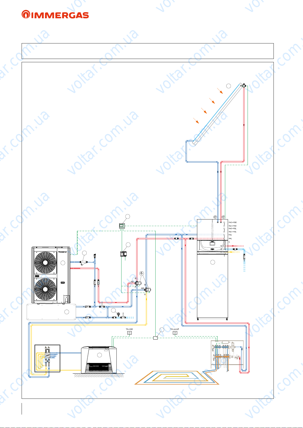
TA on/off
TA-UM
AB
6
B
A
AB
B
A
voltar.com.ua
voltar.com.ua
AUDAX TOP ErP and Integrated System
voltar.com.ua
53 HYDRAULIC DIAGRAM: AUDAX TOP
and system separate central heating/cooling + SOLAR HEATING for DHW + SYSTEM MANAGER
KEY:
1 - AUDAX TOP 12 ErP
2 - HERCULES SOLAR 200 CONDENSING ErP
3 - XL CP4 solar manifold
4 - System Manager
5 - Expansion board with address 5 for winter/summer switch-over
6 - 3-way valve kit for hot/cold system switch-over
7 - Junction box
8 - Fan-coil
9 - Inertial storage tank
10 - Standard "Y" lter for AUDAX TOP ErP
11 - System pressure gauge (to provide)
voltar.com.ua
voltar.com.ua
ErP
air conditioning only + BOILER with Storage Tank
3
voltar.com.ua
voltar.com.ua
voltar.com.ua
voltar.com.ua
4
5
10
voltar.com.ua
1
9
11
voltar.com.ua
rarescamento estivo
8
voltar.com.ua
2
7
voltar.com.ua
voltar.com.ua
voltar.com.ua
riscaldamento invernale
NOTE: this diagram is an example. It is also required to convey the condensate drain of the heat pump and boiler.
In order to guarantee proper Heat Pump operation (also with antifreeze), each system must consider inserting a bypass to guarantee a minimum ow rate of 420 l/h.
98
voltar.com.ua
voltar.com.ua
voltar.com.ua
Page 99
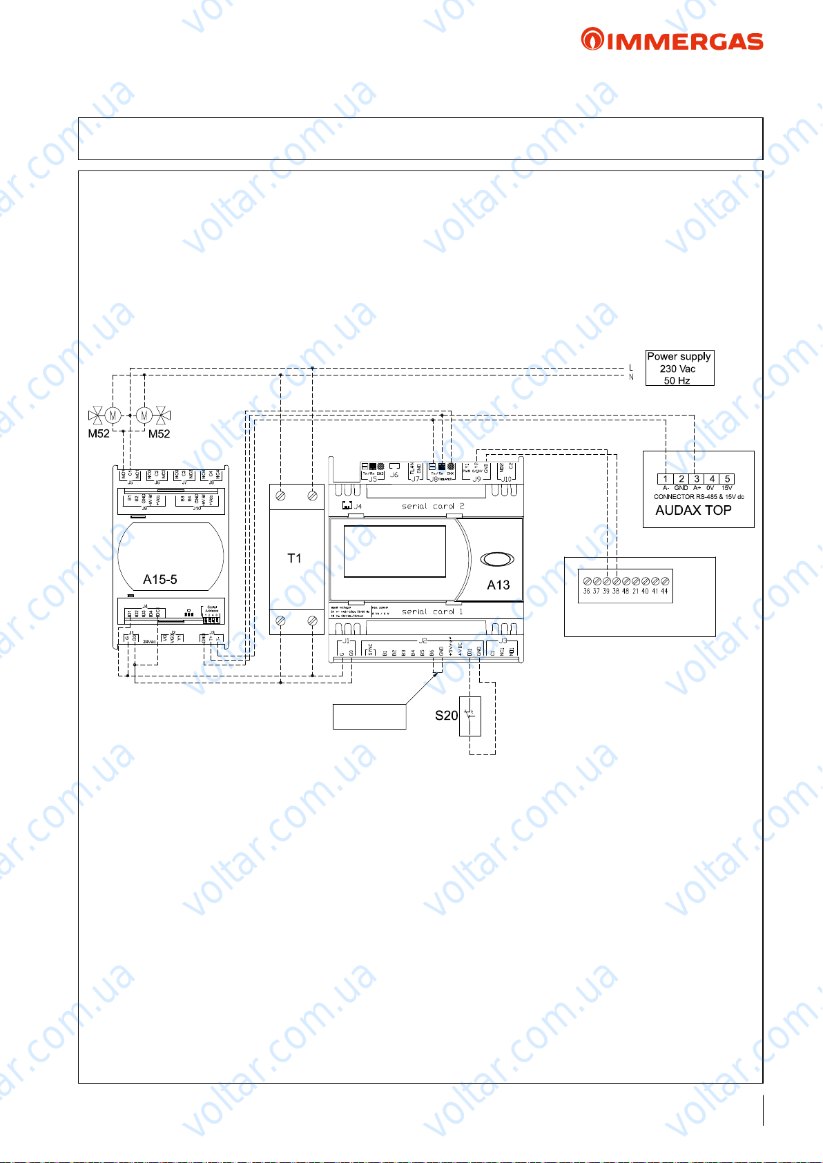
voltar.com.ua
voltar.com.ua
AUDAX TOP ErP and Integrated System
voltar.com.ua
53.1 WIRING DIAGRAM: AUDAX TOP
and system separate central heating/cooling + SOLAR HEATING for DHW + SYSTEM MANAGER
voltar.com.ua
voltar.com.ua
ErP
air conditioning only + BOILER with Storage Tank
voltar.com.ua
voltar.com.ua
voltar.com.ua
voltar.com.ua
COMMUT.
HEATING/
COOLING
voltar.com.ua
Boiler alarm
input
KEY:
A13 - System Manager
A15-5 - Expansion for summer/winter circuits
S20 - Room thermostat/contact ON-OFF request
M52 - 3-way summer/winter switch-over valve
T1 - 24 Vac transformer (not supplied with the System Manager)
NOTA: with this setting, the Control Panel (standard with
AUDAX TOP
ErP) is not used.
voltar.com.ua
BOILER
voltar.com.ua
voltar.com.ua
voltar.com.ua
voltar.com.ua
voltar.com.ua
voltar.com.ua
99
voltar.com.ua
Page 100
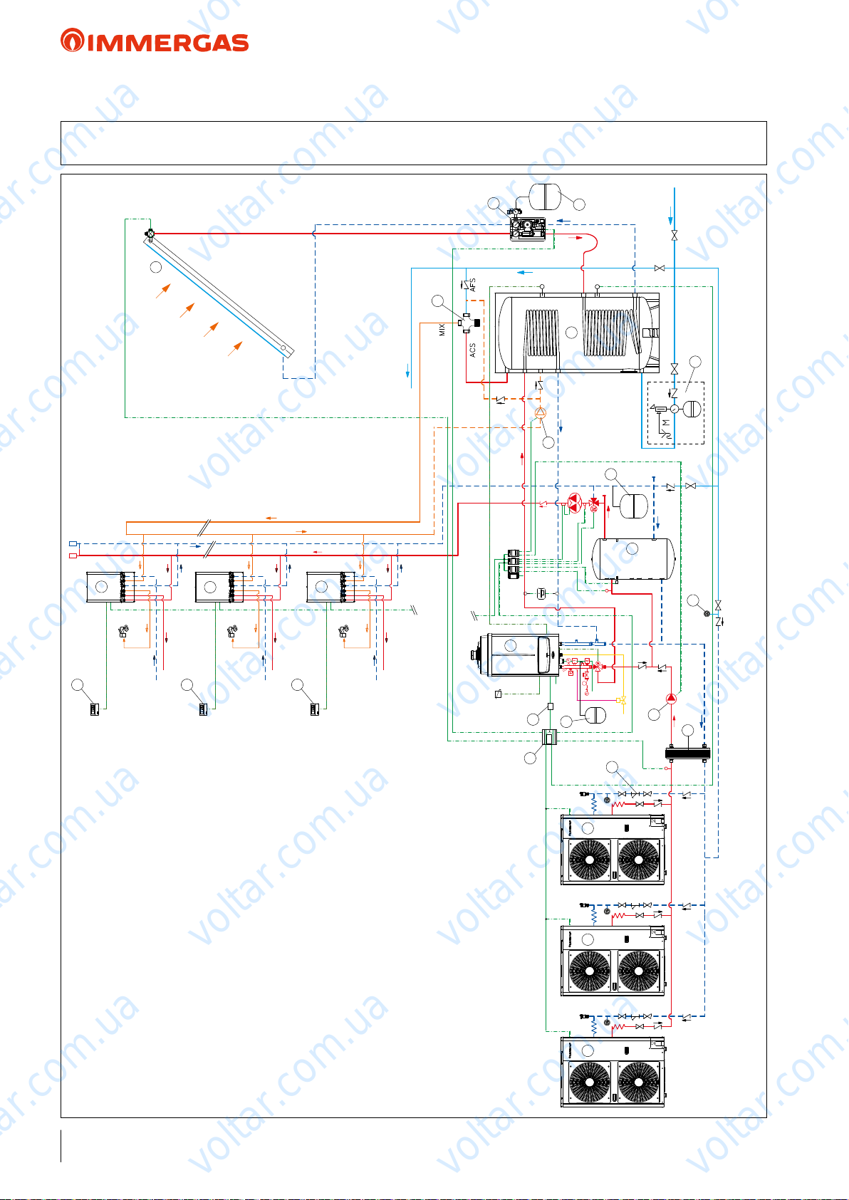
voltar.com.ua
voltar.com.ua
voltar.com.ua
AUDAX TOP ErP and Integrated System
54 HYDRAULIC DIAGRAM: AUDAX TOP ErP cascade air conditioning only) + HIGH OUTPUT boiler +
thermal ywheel and MIXED zone + SOLAR HEATING for D.H.W. PRODUCTION + SYSTEM MANAGER
5
3
voltar.com.ua
to the counters
voltar.com.ua
12
12
12
voltar.com.ua
11
voltar.com.ua
6
Water-DHW network
voltar.com.ua
4
7
10
9
voltar.com.ua
8
direct zone
Storage tank
managed as a
Thermostat with
summer/winter
calibration
20
2
13
13
voltar.com.ua
voltar.com.ua
13
voltar.com.ua
15
16
14
111
voltar.com.ua
19
17
voltar.com.ua
18
voltar.com.ua
100
KEY:
1 - AUDAX TOP 16 ErP
2 - VICTRIX PRO ErP
3 - XL CP4 solar manifold
4 - Double coil storage tank unit
5 - Solar ErP circulation unit with safety valve
6 - Solar expansion vessel
7 - Expansion valve and safety valve for DHW
8 - Hot/cold thermal ywheel (managed as zone)
9 - Heating system expansion vessel
10 - DHW recirculation electric pump ring
11 - DHW thermostatic mixer
12 - Counting unit
13 - ON/OFF Room thermostat
14 - System Manager
15 - Boiler enabling relay
16 - Boiler primary expansion vessel
17 - Standard "Y" lter for AUDAX TOP ErP
18 - AUDAX TOP ErP/system heat exchanger/separator circuits
19 - Post-heat exchanger electric circulation pump
20 - System pressure gauge (to provide)
voltar.com.ua
voltar.com.ua
voltar.com.ua
NOTE: this diagram is an example. It is also required to convey the condensate drain of the heat pump and boiler.
In order to guarantee proper Heat Pump operation (also with antifreeze), each system must consider inserting a bypass to guarantee a minimum ow rate of 420 l/h.
 Loading...