

Immergas AUDAX TOP ErP, AUDAX TOP 6 ErP, AUDAX TOP 8 ErP, AUDAX TOP 12 ErP, AUDAX TOP 18 ErP Series Manual
...
HEAT PUMPS
voltar.com.ua
voltar.com.ua
voltar.com.ua
voltar.com.ua
voltar.com.ua
voltar.com.ua
voltar.com.ua
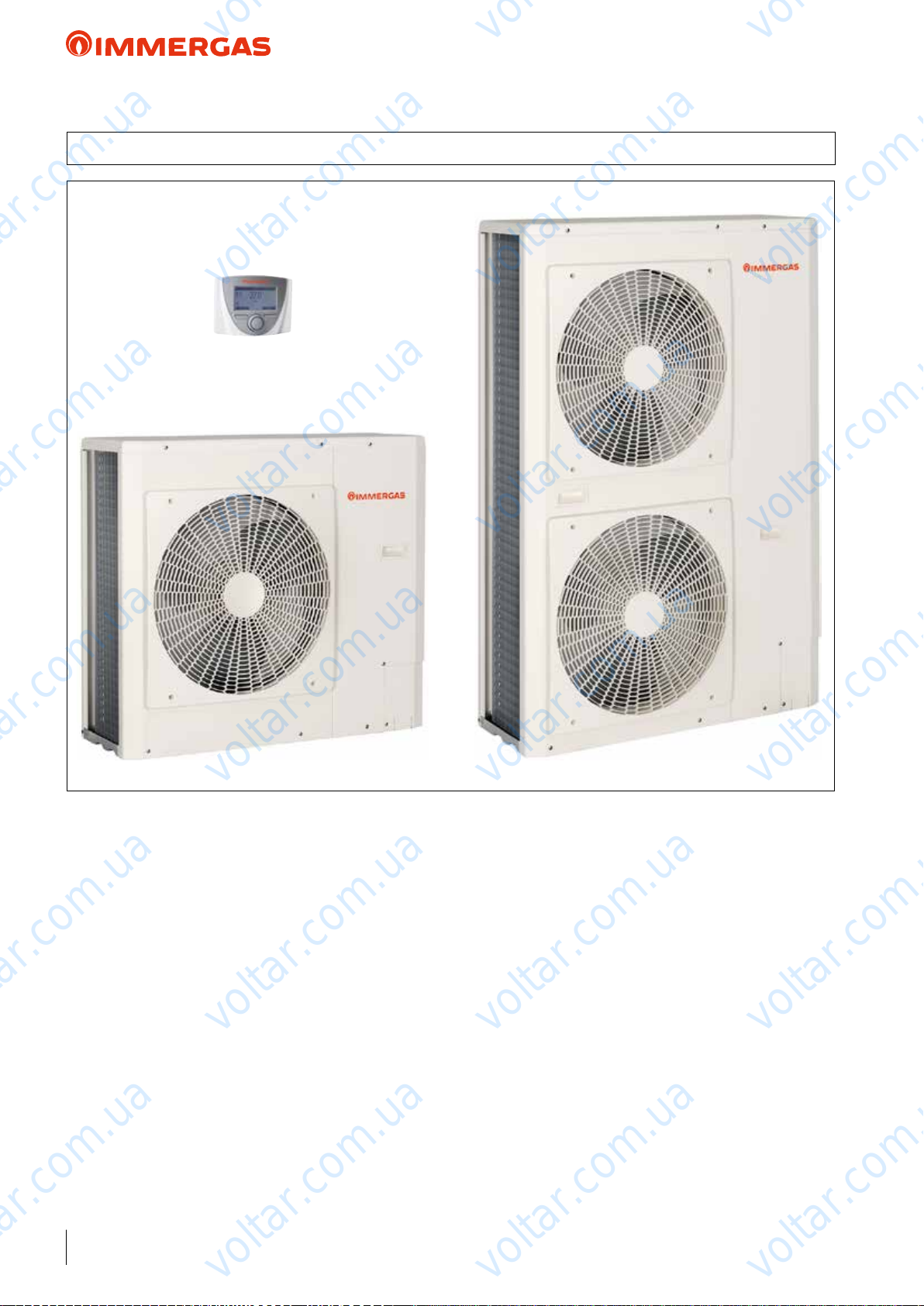
AUDAX TOP ErP
AND INTEGRATED
SYSTEMS
with reversible inverter mono-
phase and three-phase air-
water Heat Pumps
voltar.com.ua
voltar.com.ua
voltar.com.ua
voltar.com.ua
voltar.com.ua
voltar.com.ua
voltar.com.ua
voltar.com.ua
voltar.com.ua
voltar.com.ua
voltar.com.ua

voltar.com.ua
voltar.com.ua
voltar.com.ua
voltar.com.ua
voltar.com.ua
voltar.com.ua
voltar.com.ua
voltar.com.ua
voltar.com.ua
voltar.com.ua
voltar.com.ua
voltar.com.ua
voltar.com.ua
voltar.com.ua
voltar.com.ua
voltar.com.ua
voltar.com.ua
voltar.com.ua

voltar.com.ua
voltar.com.ua
voltar.com.ua
INDEX
MAIN INDEX
1 AUDAX TOP ErP DESCRIPTION .........................................................................................................................................................4
2 AUDAX TOP 6 8 12 ErP FEATURES MONOPHASE ..................................................................................................................5
3 AUDAX TOP 16 18 21 ErP FEATURES THREEPHASE ..............................................................................................................6
4 INTEGRATED SYSTEM FOR AIR CONDITIONING AND D.H.W. PRODUCTION .................................................................. 7
5 HEAT ADJUSTMENT WITH AUDAX TOP ERP CONTROL PANEL IN STANDALONE APPLICATIONS (SETTING AND
OPERATING LOGIC) .............................................................................................................................................................................. 9
6 AUDAX TOP ErP DIMENSIONS AND CONNECTIONS ................................................................................................................21
7 AUDAX TOP ErP MINIMUM INSTALLATION DISTANCES ......................................................................................................... 23
8 AUDAX TOP ErP HYDRAULIC CIRCUIT COMPONENTS ...........................................................................................................25
9 AUDAX TOP ErP OPERATING LIMITS AND ANTIFREEZE FUNCTION ................................................................................... 28
10 AUDAX TOP 6 ErP TECHNICAL DATA .............................................................................................................................................30
11 PRODUCT FICHE REGULATION 811/2013 AUDAX TOP 6 ErP .................................................................................................31
12 AUDAX TOP 6 ERP “POWER” AND “COP” CENTRAL HEATING / “EER” COOLING ............................................................. 32
13 GRAPH OF AUDAX TOP 6 ErP PUMP FLOW RATE/HEAD ...........................................................................................................34
14 AUDAX TOP 8 ErP TECHNICAL DATA ............................................................................................................................................. 35
15 PRODUCT FICHE REGULATION 811/2013 AUDAX TOP 8 ErP.................................................................................................36
16 AUDAX TOP 8 ERP “POWER” AND “COP” CENTRAL HEATING / “EER” COOLING ............................................................. 37
17 GRAPH OF AUDAX TOP 8 ErP PUMP FLOW RATE/HEAD ...........................................................................................................39
18 AUDAX TOP 12 ERP TECHNICAL DATA .......................................................................................................................................... 40
19 PRODUCT FICHE REGULATION 811/2013 AUDAX TOP 12 ErP ...............................................................................................41
20 AUDAX TOP 12 ERP “POWER” AND “COP” CENTRAL HEATING / “EER” COOLING ........................................................... 42
21 GRAPH OF AUDAX TOP 12 ErP PUMP FLOW RATE/HEAD .........................................................................................................44
22 AUDAX TOP 16 ErP TECHNICAL DATA ...........................................................................................................................................45
23 PRODUCT FICHE REGULATION 811/2013 AUDAX TOP 16 ErP ...............................................................................................46
24 AUDAX TOP 16 ERP “POWER” AND “COP” CENTRAL HEATING / “EER” COOLING ........................................................... 47
25 GRAPH OF AUDAX TOP 16 ErP PUMP FLOW RATE/HEAD .........................................................................................................49
26 AUDAX TOP 18 ErP TECHNICAL DATA ...........................................................................................................................................50
27 PRODUCT FICHE REGULATION 811/2013 AUDAX TOP 18 ErP ...............................................................................................51
28 AUDAX TOP 18 ERP “POWER” AND “COP” CENTRAL HEATING / “EER” COOLING ........................................................... 52
29 GRAPH OF AUDAX TOP 18 ErP PUMP FLOW RATE/HEAD .........................................................................................................54
30 AUDAX TOP 21 ErP TECHNICAL DATA ...........................................................................................................................................55
31 PRODUCT FICHE REGULATION 811/2013 AUDAX TOP 21 ErP ...............................................................................................56
32 AUDAX TOP 21 ERP “POWER” AND “COP” CENTRAL HEATING / “EER” COOLING ........................................................... 57
33 GRAPH OF AUDAX TOP 21 ErP PUMP FLOW RATE/HEAD .........................................................................................................59
34 AUDAX TOP 6 8 12 16 ErP P.C.B. .................................................................................................................................................. 60
35 AUDAX TOP 6 8 12 16 ErP CONTROL DIAGRAM .................................................................................................................... 63
36 AUDAX TOP 6 8 12 16 ErP TERMINAL BLOCK ELECTRICAL CONNECTIONS ................................................................ 64
37 AUDAX TOP 18 21 ErP P.C.B. ............................................................................................................................................................65
38 AUDAX TOP 18 21 ErP CONTROL DIAGRAM ..............................................................................................................................66
39 AUDAX TOP 18 21 ErP TERMINAL BLOCK ELECTRICAL CONNECTIONS ...........................................................................67
40 ELECTRIC CONNECTION CABLES FEATURES ............................................................................................................................ 68
41 SYSTEM MANAGER ............................................................................................................................................................................. 69
42 ZONE REMOTE CONTROL ............................................................................................................................................................... 76
43 ROOM TEMPERATURE/HUMIDITY SENSOR ................................................................................................................................ 76
44 EXPANSION BOARD FOR ZONE MANAGEMENT ........................................................................................................................76
45 SYSTEM DISTRIBUTION KIT ............................................................................................................................................................ 77
46 DEHUMIDIFIER ................................................................................................................................................................................... 81
47 INTRODUCTION WITH COMMENTARY TO INTEGRATED SYSTEMS: MAIN APPLICATIONS ...........................................85
48
DIAGRAM AUDAX TOP ERP AND 2 LOW TEMPERATURE ZONES+ SOLAR HEATING FOR D.H.W. PRODUCTION + MANAGER
49 DIAGRAM AUDAX TOP ErP + CONTROL PANEL TO CONTROL THE ROOM + SOLAR PACK ............................................ 90
50 DIAGRAM AUDAX TOP ErP AIR CONDITIONING ONLY + BOILER PLUS + 2 LOW TEMPERATURE ZONES AND
1 DIRECT ZONE + SOLAR HEATING FOR D.H.W. PRODUCTION + SYSTEM MANAGER ...................................................92
51 DIAGRAM AUDAX TOP ErP + BOILER WITH 1 HIGH TEMPERATURE ZONE + 2 LOW TEMPERATURE ZONES
+ SOLAR HEATING FOR DHW + SYSTEM MANAGER ..................................................................................................................94
52 DIAGRAM AUDAX TOP ErP + PLUS BOILER AND 2 LOW TEMPERATURE ZONES + STORAGE TANK UNIT FOR D.H.W.
PRODUCTION + SYSTEM MANAGER.............................................................................................................................................. 96
53
DIAGRAM AUDAX TOP ERP AIR CONDITIONING ONLY + BOILER WITH INTEGRATED STORAGE TANK UNIT + SOLAR
HEATING FOR D.H.W. PRODUCTION, SEPARATE CENTRAL HEATING/COOLING SYSTEM + SYSTEM MANAGER
54 DIAGRAM AUDAX TOP ErP IN CASCADE AIR CONDITIONING ONLY + HIGH POWER BOILER + THERMAL
FLYWHEEL AND MIXED ZONE + SOLAR HEATING FOR D.H.W. PRODUCTION + SYSTEM MANAGER ...................... 100
55 DIAGRAM AUDAX TOP ErP + BOILER AND 2 LOW TEMPERATURE ZONES + SOLAR HEATING FOR D.H.W.
PRODUCTION AND CENTRAL HEATING + SYSTEM MANAGER ........................................................................................... 102
56 OPTIONAL WHICH CAN BE COUPLED .......................................................................................................................................104
57 MAIN INERTIAL STORAGE TANK TECHNICAL FEATURES ..................................................................................................... 107
voltar.com.ua
voltar.com.ua
voltar.com.ua
voltar.com.ua
voltar.com.ua
voltar.com.ua
voltar.com.ua
voltar.com.ua
voltar.com.ua
voltar.com.ua
voltar.com.ua
...88
voltar.com.ua
.......................98
voltar.com.ua
voltar.com.ua
3
voltar.com.ua
voltar.com.ua
1 AUDAX TOP ErP DESCRIPTION
voltar.com.ua
voltar.com.ua
AUDAX TOP ErP
voltar.com.ua
voltar.com.ua
voltar.com.ua
voltar.com.ua
voltar.com.ua
voltar.com.ua
voltar.com.ua
A range of air/water reversible heat pumps with inverter technology. e mono-phase versions are available with AUDAX
TOP 6 ErP, AUDAX TOP 8 ErP and AUDAX TOP 12 ErP
models to full central heating and cooling requirements for
homes, oces, shops, etc...; while the three-phase versions are
available with AUDAX TOP 16 ErP, AUDAX TOP 18 ErP and
AUDAX TOP 21 ErP models to full central heating and cooling
requirements for large domestic systems (newly built large homes
such as duplexes, three-unit houses, condominiums), as well as
oces, shops, artisan activities, etc..
ese appliances are distinguished for their high energy eciency
and contained sound levels. ey can be used as a single generator to assist the system, but also inside an integrated system
(for example, with a heat pump - boiler - solar heating). ey
are engineering solutions that can be perfectly integrated with
each other, which allow to attain maximum benet from the
various energy production systems on the basis of the respective
eciency parameters.
For the entire system to operate correctly, Immergas oers an
“intelligent” system Manager capable of identifying the most
economical energy source at a given time and therefore choose
voltar.com.ua
voltar.com.ua
the right appliance to activate.
All AUDAX TOP ErP series models are equipped with a system
side plate heat exchanger and low energy consumption circulation pump, which facilitate installation. e maximum ow
temperature set-point with central heating is 60 °C (57 °C for
AUDAX TOP 21 ErP), which enables use of radiator systems
as well as fan coil or radiant systems.
e entire range complies with the requirements of ErP Directive
(2009/125/EC) and ELD (2010/30/EC). Various hydraulic,
electric and electronic kits are available, which enable exible
use in all circumstances.
voltar.com.ua
voltar.com.ua
voltar.com.ua
4
voltar.com.ua
voltar.com.ua
voltar.com.ua

voltar.com.ua
voltar.com.ua
AUDAX TOP ErP
2 AUDAX TOP 6 8 12 ErP FEATURES MONOPHASE
voltar.com.ua
6 kW, 8 kW and 12 kW mono-phase inverter air/water heat
pumps for winter and summer air conditioning. e galvanised
steel structure makes the machines particularly suitable for
outdoor installation.
Main components:
• Control Panel - standard supply - which enables you to pro-
gram the machine and also functions as a room temperature/
humidity sensor. It also displays the error codes in the event
of malfunctions;
• R410A refrigerant gas (pre-loaded in the machine);
• Twin Rotary compressor with hybrid inverter activation in
direct current with PAM (Pulse Amplitude Modulation) and
PWM (Pulse Width Modulation) logic to oer improved
reliability, low energy consumption and vibration-free operation in all operating conditions and acoustic insulation with
sound-absorbing materials.
• cooling circuit including a compressor and air/gas refrigerant
nned coil, two-way electronic throttle valve, refrigerant gas/
water insulated stainless steel plate heat exchanger, 4-way
reversing valve (reversible heat pump cycle or cooling cycle
operation);
• variable speed fan with a 3-blade impeller characterised by an
innovative prole designed to guarantee better distribution of
air and contained sound levels (AUDAX TOP 6 - 8 ErP);
• double variable speed fan with a 3-blade impeller characterised
by an innovative prole designed to guarantee better distribution of air and contained sound levels (AUDAX TOP 12 ErP);
• system low energy consumption pump and ow switch to
ensure there is sucient water circulation to guarantee correct
operation of the hydronic and cooling circuits;
• 2 litre internal expansion vessel (AUDAX TOP 6 - 8 ErP);
• 3 litre internal expansion vessel (AUDAX TOP 12 ErP);
• 3 bar system safety valve;
• included and standard supply are the water Y lter 1”, vibra-
tion-dampening devices, condensate drain ttings and cable
clamp to pass electric cables;
• ow and return 1” M hydraulic connections situated at the
rear;
• electronic management system equipped with various sensors
situated in key positions of the cooling circuit to electronically
detect the system's operating status. e system's ow water
temperature is detected by means of a probe;
• option to pilot a 3-way diverter valve directly from AUDAX
TOP ErP for D.H.W. production heating and an external
booster pump on the system;
• maximum system water ow temperature up to 60 °C;
• operation up to outdoor air temperature of -20°C in winter
and +46°C in summer;
• protection against freezing up to -10°C as a result of periodic
activation of the pump and AUDAX TOP ErP cooling circuit
(with power supply voltage);
• IPX4 electrical insulation rating.
voltar.com.ua
voltar.com.ua
voltar.com.ua
voltar.com.ua
System solutions:
• Standalone system with AUDAX TOP ErP and integrative
resistance;
• can be coupled to a separate storage tank for DHW;
• can be coupled to a boiler via the System manager;
• can be coupled to a boiler and the solar heating system via the
voltar.com.ua
System manager.
• can be installed as a set conguration with the System manager.
Is available in the model:
• AUDAX TOP 6 ErP code 3.025557
• AUDAX TOP 8 ErP code 3.025558
• AUDAX TOP 12 ErP code 3.025560
EC Declaration Of Conformity.
voltar.com.ua
voltar.com.ua
voltar.com.ua
voltar.com.ua
voltar.com.ua
voltar.com.ua
voltar.com.ua
voltar.com.ua
voltar.com.ua
5
voltar.com.ua

voltar.com.ua
voltar.com.ua
AUDAX TOP ErP
3 AUDAX TOP 16 18 21 ErP FEATURES THREEPHASE
voltar.com.ua
16 kW, 18 kW and 21 kW three-phase inverter air/water heat
pump for winter and summer air conditioning. e galvanised
steel structure makes the machines particularly suitable for
outdoor installation.
Main components:
• Control Panel - standard supply - which enables you to program the machine and also functions as a room temperature/
humidity sensor. It also displays the error codes in the event
of malfunctions;
• R410A refrigerant gas (pre-loaded in the machine);
• twin Rotary compressor with hybrid inverter activation in
direct current with PAM (Pulse Amplitude Modulation) and
PWM (Pulse Width Modulation) logic to oer improved
reliability, low energy consumption and vibration-free operation in all operating conditions and acoustic insulation with
sound-absorbing materials.
• cooling circuit including a compressor and air/gas refrigerant
nned coil, two-way electronic throttle valve (2 in the 21 kW
version), refrigerant gas/water insulated stainless steel plate
heat exchanger, 4-way reversing valve (reversible heat pump
cycle or cooling cycle operation);
• double fan variable speed with a 3-blade impeller characterised
by an innovative prole designed to guarantee better distribution of air and contained sound levels;
• modulating system low energy consumption pump and ow
switch to ensure there is sucient water circulation to guarantee correct operation of the hydronic and cooling circuits;
• 3 litre internal expansion vessel (16 kW);
• 8 litre internal expansion vessel (18 - 21 kW);
• 3 bar system safety valve;
• included and standard supply are the water Y lter 1”, vibration-dampening devices, condensate drain ttings and cable
clamp to pass electric cables;
• ow and return 1” M hydraulic connections situated at the
rear;
• electronic management system equipped with various sensors
situated in key positions of the cooling circuit to electronically
detect the system's operating status. e system's ow water
temperature is detected by means of a probe;
• option to pilot a 3-way diverter valve directly from AUDAX
TOP ErP for D.H.W. production heating and an external
booster pump on the system;
• maximum system water ow temperature up to 60 °C (57 °C
for AUDAX TOP 21 ErP);
• operation up to outdoor air temperature of -20°C in winter
and +46°C in summer;
• for AUDAX TOP 16 ErP protection against freezing up to -10°C
(with power supply voltage) as a result of periodic activation of the
pump and AUDAX TOP ErP cooling circuit;
• for AUDAX TOP 18-21 ErP protection against freezing up to -10°C
(with power supply voltage) as a result of periodic activation of the
pump and electric resistances;
• IPX4 electrical insulation rating.
voltar.com.ua
voltar.com.ua
voltar.com.ua
voltar.com.ua
System solutions:
• standalone system with AUDAX TOP ErP and integrative
resistance;
• can be coupled to a separate storage tank for DHW;
• can be coupled to a boiler via the System manager;
• can be coupled to a boiler and the solar heating system via the
voltar.com.ua
System manager.
• can be installed as a set conguration with the System manager.
Is available in the model:
• AUDAX TOP 16 ErP code 3.025562
• AUDAX TOP 18 ErP code 3.025563
• AUDAX TOP 21 ErP code 3.026940
EC Declaration Of Conformity.
voltar.com.ua
voltar.com.ua
voltar.com.ua
voltar.com.ua
voltar.com.ua
voltar.com.ua
voltar.com.ua
6
voltar.com.ua
voltar.com.ua
voltar.com.ua
voltar.com.ua
voltar.com.ua
AUDAX TOP ErP and Integrated System
voltar.com.ua
voltar.com.ua
voltar.com.ua
voltar.com.ua
voltar.com.ua
voltar.com.ua
voltar.com.ua
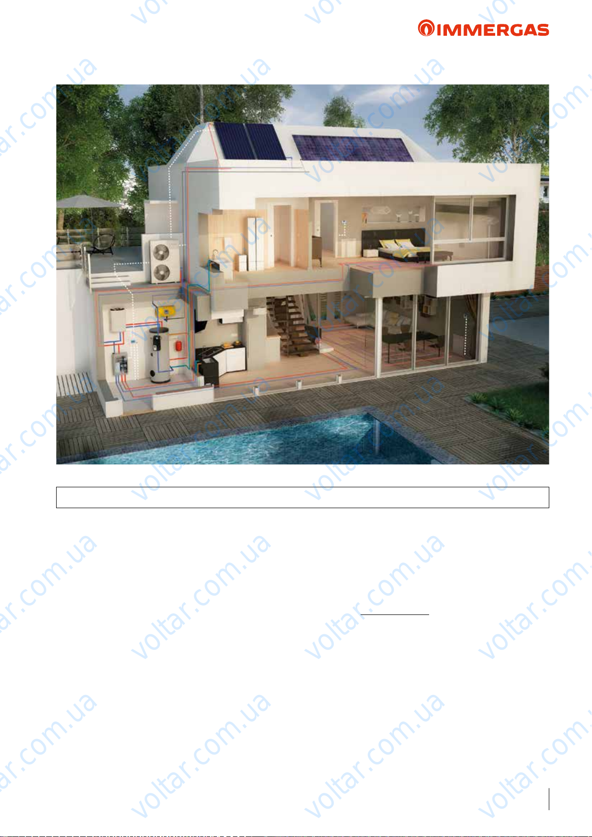
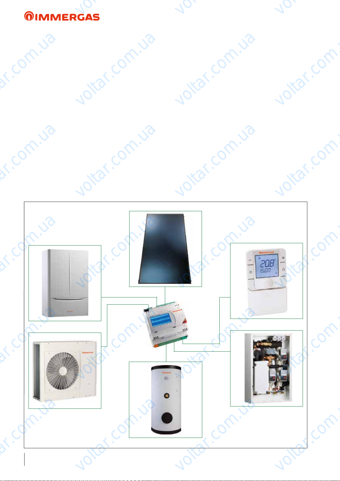
4 INTEGRATED SYSTEM FOR AIR CONDITIONING AND D.H.W. PRODUCTION
Comprised of a boiler – solar heating – heat pump and possibly
photovoltaic – etc, they are the natural evolution of air-conditioning systems: with very high seasonal eciency, low energy
consumption and reduced polluting emissions.
ey are engineering solutions that can be perfectly integrated
with each other, which allow to attain maximum benet from the
various energy production systems on the basis of the respective
eciency parameters.
For the entire system to operate correctly, Immergas oers a
System Manager, able to:
- always make use of the most convenient heat source;
- keep the system performance high in every circumstance;
- control and command the entire system with a unique "brain"
(i.e. the System Manager);
- promote heat pump activation with a system that generates
electricity from renewable sources.
Basically, the System Manager is a supervisor that can control
the entire system).
Amongst other things, the following main operations are necessary:
voltar.com.ua
- acquire outdoor temperature (from the external probe, inserted
- set central heating side and cooling side (if provided) climatic
- congure the fuel cost (e.g. methane);
- congure the electric energy cost;
- set the AUDAX TOP ErP minimum integration (cut o) T.
e point of economic balance between the gas boiler and the
heat pump is a COP value between 2.4 and 2.6 approximately
(approximate value referred to methane); this value changes
based on the cost of electrical power and gas, in the location
voltar.com.ua
where the system is installed.
With sucient Toutdoor to full minCOP economical convenience, or Toutdoor is higher than Tminimum integration (cut o), the
heat pump starts and the performance eciency conditions are
constantly monitored. On the contrary, if the environmental
conditions are such that the AUDAX TOP ErP coecient of
performance tends towards lower values than COPmin for economical convenience, or outdoor T is less than minimum integration
(cut o) T, the system Manager starts the boiler (or integrative
resistance).
voltar.com.ua
as per standard on the heat pump);
curve operation to determine the system's ow temperature;
voltar.com.ua
voltar.com.ua
voltar.com.ua
voltar.com.ua
voltar.com.ua
7
voltar.com.ua
voltar.com.ua
voltar.com.ua
AUDAX TOP ErP and Integrated System
voltar.com.ua
Each time AUDAX TOP ErP is operating, the Manager enables
an additional control, which checks the time it takes the system
to reach full operation: when a maximum time is exceeded (can
be set dierently between C.H. and D.H.W.) for the heat pump
to reach the owT, the boiler or integrative electrical resistance
is started.
It is also possible to choose the integration operation method
(boiler/resistance) between simultaneous or alternative Heat
Pump.
In all cases where radiant panels are also included for summer
cooling, alongside dehumidiers (see previous picture), the
System Manager will also monitor the dew point through the
installation of room probes (Immergas). anks to this intelligent
function the System Manager can increase the ow temperature
to the radiant panels by about 1°C (up to a maxT of 18°C - maximum limit of the cooling heat pump), avoiding the phenomenon
of condensation on the surface of the structure. is function can
only be activated with an Immergas accessory kit that controls
humidity. In some cases, for example, the System Manager can
turn the heat pump o if the ow temperature to the radiant
panels is not suciently corrected.
voltar.com.ua
voltar.com.ua
If on the other hand, there is a high temperature zone in the
system, in addition to the low temperature one, it will be served
exclusively by the boiler through an accordingly congured
dedicated expansion connected to the System Manager.
D.H.W: operation: amongst the possible congurations with
integrated systems is the option to connect the boiler and
AUDAX TOP ErP parallel with the same coil, and use a storage
tank probe with one DHW set for the entire storage tank, and set
voltar.com.ua
it in the system's Manager. If the system Manager is connected
to the boiler on external probe clamps (pre-set models), if the
set DHW temperature is < 50°C, the heat pump starts (always
checking the aforesaid convenience); however, if it is > 50°C,
AUDAX TOP ErP heats up to 50°C, then the boiler starts; if
there is no boiler but there is storage tank integrative electrical
resistance, the water is brought to 50°C via the heat pump and
AUDAX TOP ErP is then disabled, leaving the resistance to
integrate to the pre-set value.
In systems where there is a boiler or an integrative electrical
resistance on the storage tank, in addition to the heat pump, it
is also possible to enable the anti-legionella function.
voltar.com.ua
voltar.com.ua
voltar.com.ua
voltar.com.ua
voltar.com.ua
voltar.com.ua
voltar.com.ua
voltar.com.ua
voltar.com.ua
8
voltar.com.ua
voltar.com.ua
voltar.com.ua
voltar.com.ua
voltar.com.ua
AUDAX TOP ErP
5 HEAT ADJUSTMENT WITH AUDAX TOP ErP CONTROL PANEL IN
STANDALONE APPLICATIONS (SETTING AND LOGIC OPERATION)
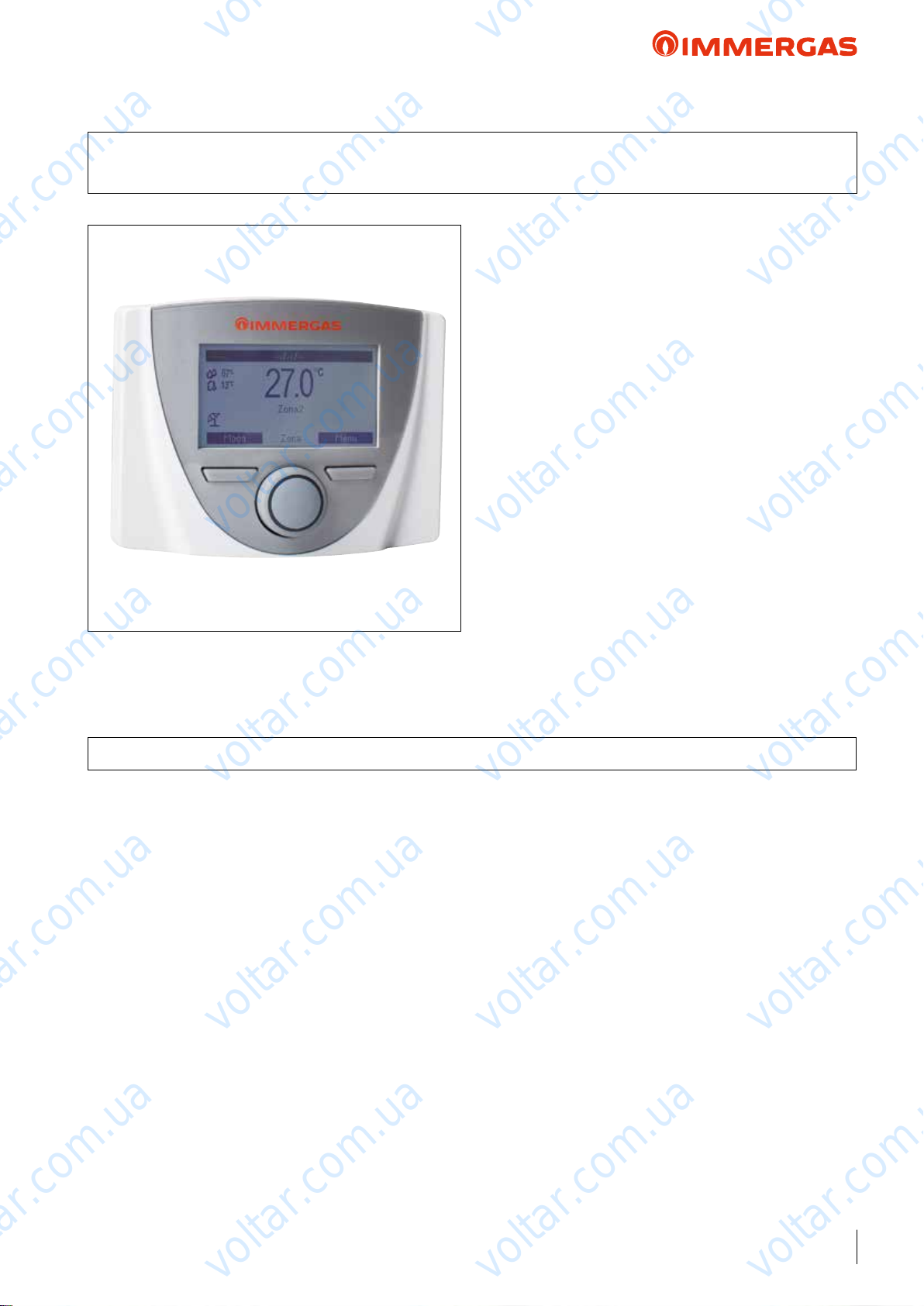
e Control Panel (standard supply with AUDAX TOP ErP)
enables programming of several operating options and relative
voltar.com.ua
voltar.com.ua
temperature/humidity control of the system.
voltar.com.ua
For example, the Control Panel acquires data regarding outdoor
temperature (from the external probe), system ow temperature
(regarding the pre-set climatic curve), and also the room's humidity percentage.
e standard Control Panel supplied is connected to a specic
terminal block on AUDAX TOP ErP, which enables you to
program the machine and also functions as a room temperature/
humidity sensor. It also displays the error codes in the event of
malfunctions.
e room sensor function can be disabled in order to use it only
to display the heat pump statuses and leave AUDAX TOP ErP
external control management on/o.
e user interface is composed of an LCD display, keys and an
encoder central knob.
voltar.com.ua
N.B.: With system Manager applications, the Control Panel
(standard) can also function as a room temperature/humidity
probe of a system's zone.
voltar.com.ua
voltar.com.ua
voltar.com.ua
Factory set device class: "VI"
Ref. European Commission Notice 2014/C 207/02
5.1 TECHNICAL FEATURES
e Control Panel (standard) with Standalone conguration,
enables:
• Operation with variable ow temperature according to outdoor
temperature (through the standard AUDAX TOP ErP external
probe supplied);
• Machine time band operation (C.H and cooling) in Comfort
or Economy mode;
• Any operation anomalies with error codes via system self-diagnosis displayed on the screen.
e Control Panel also manages the following data:
• External temperature (via external probe as per standard with
AUDAX TOP ErP);
• System ow temperature settings (C.H and cooling);
• Instant outlet temperature from the machine;
• Dew temperature;
• No. of machine operating hours.
Please note that AUDAX TOP ErP can:
• Directly pilot one/two 3-way diverter valves for D.H.W.
production, and can manage activation of an external booster
pump on the system;
• Manage activation of an auxiliary heat source (e.g. electrical
resistance);
voltar.com.ua
voltar.com.ua
voltar.com.ua
• Manage and an external alarm that forces machine shutdown;
• Limit the machine's frequency (to reduce noise).
NOTE: With Standalone applications to manage any dehumidiers, you can opt for On/O room thermostats + On/
O humidistats (connected parallel with AUDAX TOP ErP),
with a relay to split the humidistat request and also take it to
the dehumidiers.
TECHNICAL DATA
• Dimensions: 100 x 129 x 37 mm (H x L x D);
• Supply voltage: 15 Vdc (directly from the Heat Pump terminal
block);
• Maximum input: 2 VA;
voltar.com.ua
• 4-pole cable connection (type H03VV-F 5 x 0.75 mm2 ), max
length 50 m. Use wires having minimum sections of 0.5 mm2
and maximum 1.5 mm2;
• Casing protection rating: IP20.
voltar.com.ua
voltar.com.ua
voltar.com.ua
voltar.com.ua
9
voltar.com.ua
voltar.com.ua
5.2 PROGRAMMING MENU
4
2
1 - Main parameters switch with button to
2 - Left context button
3 - Right context button
4 - Display
12:34 Fr 3 Jan 2014
voltar.com.ua
67%
20.6
13°C
Room set 21.0°C
Mode Menu
conrm and save data
voltar.com.ua
°C
3
1
voltar.com.ua
Once the device is powered, it goes into the status prior to switcho. Press the “Modo” (Mode) (2) button to cyclically select the
desired mode amongst those available.
Depending on the system's conguration, the main screen displays various information regarding the system.
voltar.com.ua
Press the “Menu” (3) button to access a list of variables that
enable you to customise use of the system.
To browse the menus, which can be accessed by pressing the
relative “RH” or “LH” context buttons, scroll through the
sub-menus displayed by turning the main switch (1).
Press the said main switch (1) to select the one highlighted.
erefore, by pressing repeatedly, you can scroll down the menu
levels and go back to a previous level by pressing the “Indietro”
(Back) context button. To exit the menu completely, press the
“Esci” (Exit) button, which will take you back to the initial page
of normal operation.
To conrm the parameter change, press the main switch (1).
voltar.com.ua
voltar.com.ua
AUDAX TOP ErP
voltar.com.ua
voltar.com.ua
MAIN MENU
Menu item Description
Set Point Zone Denes the operating parameters to manage the zone
Set Point DHW Denes the operation parameters in domestic circuit mode
Time and Program Denes the date/time and time operating ranges
Information Display system operating data
Historical alarm code Displays the list of the last 10 anomalies
Service Password protected menu dedicated to a qualied technician
Language Denes the control panel operation language
voltar.com.ua
voltar.com.ua
voltar.com.ua
voltar.com.ua
voltar.com.ua
voltar.com.ua
10
N.B. PARAMETERS ONLY VALID FOR AUDAX TOP 18 - 21 ErP
voltar.com.ua
voltar.com.ua
voltar.com.ua
voltar.com.ua
voltar.com.ua
AUDAX TOP ErP
5.3 USER PROGRAMMING MENU
Menu Set Point Zone
Menu item Description Range Default
Set comfort heat. Room temperature in central heating zone Comfort mode 15 ÷ 35 °C 20
Set economy heat. Room temperature in central heating zone Economy mode 5 ÷ 25 °C 17
Set ow heat. Flow temperature in room zone central heating mode 20 ÷ 60°C 40
Oset ow heat. Oset temperature for central heating zone
Set comfort cool. Room temperature in cooling zone Comfort mode 15 ÷ 35 °C 25
Set economy cool. Room temperature in cooling zone Economy mode 15 ÷ 35 °C 28
Set ow cool. Flow temperature in room zone cooling mode 4 ÷ 25 °C 8
Oset ow cool. Oset temperature for cooling zone
Menu item Description Range Default
Set comfort DHW storage temperature in Comfort phase 30 ÷ 60 °C 50
Set economy DHW storage temperature in Economy phase 30 ÷ 45 °C 30
voltar.com.ua
Menu Set point DHW
voltar.com.ua
voltar.com.ua
- 15 ÷ + 15
°C
-15 ÷ + 15
°C
voltar.com.ua
voltar.com.ua
voltar.com.ua
0
0
voltar.com.ua
Menu Time and Programs
Menu item Description Range Default
Date and time Current date and time setting
Time slots Denes the time range for operation in Comfort and Economy mode
Program Zone Time programming for controlled zone
Program DHW DHW operation time programming
Denes the period during which the system disables both hot water heating and
voltar.com.ua
Program Holiday
Menu item Description
Flow temperature Instant outlet temperature from the system
Return temperature Instant inlet temperature to the system
External temperature External temperature detected by the external probe
Flow temp. system calc. Flow temperature requested by the generators
Dew point Dew temperature
Temp DHW Storage water temperature
Firmware board version Heat pump control board software revision
Firmware display version Display software revision installed on the control panel
H.P. hours of operation Number of operating hours of the heat pump
Mode of operation H.P. Describes the heat pump operation mode.
room central heating and/or cooling functions.
At the end of the set days, the previously active functions will be reset.
Menu Information
voltar.com.ua
voltar.com.ua
voltar.com.ua
Mon - Sun
voltar.com.ua
voltar.com.ua
Mon - Fri
Cal 1
Sat - Sun
Cal 3
Cal 1
Disabled
N.B. PARAMETERS ONLY VALID FOR AUDAX TOP 18 - 21 ErP
voltar.com.ua
voltar.com.ua
11
voltar.com.ua
voltar.com.ua
voltar.com.ua
AUDAX TOP ErP
Menu Historical alarm code
Description
Displays the history log of the last 10 anomalies
Menu Service
Menu item Description Range Default
Password protected menu dedicated to a qualied technician
voltar.com.ua
Menu Language
Menu item Description Range Default
Language Denes the control panel operation language ITA - ENG ITA
voltar.com.ua
voltar.com.ua
voltar.com.ua
voltar.com.ua
voltar.com.ua
voltar.com.ua
voltar.com.ua
voltar.com.ua
voltar.com.ua
12
voltar.com.ua
voltar.com.ua
voltar.com.ua
voltar.com.ua
voltar.com.ua
voltar.com.ua
voltar.com.ua
voltar.com.ua
AUDAX TOP ErP
5.4 MAINTENANCE TECHNICIAN PROGRAMMING MENU
Menu Service
Menu item Description Range
Denition of zone Zone system sub-menu settings -
Dening plant Sub-menu to dene the devices connected to the system -
Device conguration Sub-menu to set the device's conguration -
ermoreg. heat. Central heating thermoregulation setting sub-menu -
ermoreg. cool Cooling thermoregulation setting sub-menu -
ermoreg. parameters Parameters thermoregulation setting sub-menu -
Integration System integration setting sub-menu -
Heat pump Heat pump operating parameters sub-menu -
Manual Manual operating parameters sub-menu -
Factory settings Default settings restore sub-menu Yes / No
voltar.com.ua
voltar.com.ua
voltar.com.ua
voltar.com.ua
Menu Service -> Denition of Zone
Menu item Description Range Default
Mode Display the operating mode
Room control inter-
face
Enable Remote
Control
Enable thermostat
Enable dew point Enable operation with a humidity probe in the control panel. Yes / No No
Menu item Description Range Default
External probe Enables operation with the external probe.
Enable DHW Operation in domestic circuit
Reduction function
Power Power percentage in reduction mode. 50% ÷ 100% 75%
Circulator control
Speed Min Value of minimum speed used in modulating operation. 19% ÷ 50% 50%
Speed Max Value of maximum speed used in modulating operation. 50% ÷ 100% 100%
Delta T Temperature delta to be maintained with modulating operation. 2 ÷ 20 5
voltar.com.ua
Enable operation of the supplied control panel if set on “R. Panel”.
If “TA” set, the central heating and cooling requests will be made based on the
request of an external thermostat.
Enable operation of the supplied control panel.
If “No” is set, the control panel only displays the heat pump statuses.
N.B.: setting “No”, it is compulsory to enable the room thermostat (refer to the
next item), otherwise the machine will display an anomaly.
Enable operation of a room thermostat to check the heat pump
PdC is controlled by contacts in the said P.C.B.
voltar.com.ua
Enable PdC operation frequency reduction, which is controlled by the said terminal
board.
Enable the pump operation with speed set “Max.speeed” or the modulating mode
with tracking of the “Modulating” temperature dierential.
Menu Service -> Dening Plant
voltar.com.ua
voltar.com.ua
- Heat + Cool
Remote Pan-
el/T.A.
Yes / No Ye s
Yes / No No
voltar.com.ua
No / PdC
Yes / No
Yes / No No
Max.speed/
Modulating
voltar.com.ua
voltar.com.ua
R.Panel
voltar.com.ua
Modulating
voltar.com.ua
-
No
No
N.B. PARAMETERS ONLY VALID FOR AUDAX TOP 6 - 8 - 12 - 16 ErP
N.B. PARAMETERS ONLY VALID FOR AUDAX TOP 18 - 21 ErP
voltar.com.ua
voltar.com.ua
13
voltar.com.ua

voltar.com.ua
voltar.com.ua
AUDAX TOP ErP
Menu Service -> Device conguration
Menu item Description Range Default
Setting “Yes”, the default control panel supplied manages the heat pump.
Setting “No”, the control panel does not control the heat pump and must be cou-
H.P. control
Slave address
Menu item Description Range Default
Discharge Set min
Discharge Set max
External Temp. min
External Temp. max
pled with other Immergas systems (for example, TRIO, MAGIS HERCULES, Or
System manager). If “No” is set, it displays another item “slave address”.
N.B.: if it is erroneously set to “No”, it is still possible to change the selection.
Address to congure according to the zone where the device is installed (e.g.: zone 1
= 41, zone 2 = 42, zone 3 = 43, etc...).
voltar.com.ua
Menu Service -> ermoreg. Heat
Without the external probe it denes the minimum ow temperature that can be
set by the user. With the external probe present it denes the minimum ow temperature corresponding to operation with maximum external temperature
Without the external probe it denes the maximum ow temperature that can be
set by the user. With the external probe present it denes the maximum ow temperature corresponding to operation with minimum external temperature
With the external probe present it denes at what minimum external temperature
the system must operate at the maximum ow temperature
With the external probe present it denes at what maximum external temperature
the system must operate at the minimum ow temperature
voltar.com.ua
voltar.com.ua
voltar.com.ua
Yes / No Ye s
1 ÷ 247 -
20 ÷ 45 °C 30°C
35 ÷ 60 °C 50 °C
-25 ÷ +15 °C -5 °C
-5 ÷ +45 °C 20°C
voltar.com.ua
voltar.com.ua
voltar.com.ua
Menu Service -> ermoreg. Cool
Menu item Description Range Default
Without the external probe it denes the minimum ow that can be set by the user.
Discharge Set min
Discharge Set max
External Temp. min
External Temp. max
Menu item Description Range
Room probe modul.
System inertia
Antifreeze enable Enables the room antifreeze function Yes / No Yes
Antifreeze set Allows to set the room temperature for activation of the anti-freeze function 0 ÷ 10 °C 5 °C
With the external probe present it denes the minimum ow temperature corresponding to operation with maximum external temperature
Without the external probe it denes the maximum ow that can be set by the user.
With the external probe present it denes the maximum ow temperature corresponding to operation with minimum external temperature
With the external probe present, it denes at what maximum external temperature
the system must operate at the minimum ow temperature
With the external probe present, it denes at what minimum external temperature
the system must operate at the maximum ow temperature
voltar.com.ua
Menu Service -> ermoreg. Parameters
It enables you to set operation of the control panel as modulating on/o: Set “Yes”, the
ow temperature will be varied depending on the room temperature set. Set “No”, the
ow temperature will be kept constant until the desired room temperature is reached.
N.B.: if an outdoor temperature probe is present, the ow temperature will be set
depending on the relative functioning curve
It establishes the system reaction speed according to the type of system present.
Example:
5 system with little heat inertia
10 system with normal dimensions with radiators
20 system with a lot of heat inertia (e.g. oor-standing system)
voltar.com.ua
voltar.com.ua
voltar.com.ua
4 ÷ 20 °C 7 °C
10 ÷ 25 °C 12 °C
20 ÷ 45 °C 20°C
20 ÷ 45 °C 35 °C
voltar.com.ua
Yes / No Yes
1 ÷ 20 10
voltar.com.ua
14
voltar.com.ua
voltar.com.ua
voltar.com.ua
voltar.com.ua
voltar.com.ua
voltar.com.ua
AUDAX TOP ErP
Menu Service -> Integration
Menu item Description Range Default
- None
- Sys.
Electrical integration
Contemp. Temp.
intgr.
Min. temp. of inte-
gration
Waiting time integra-
tion
Counter reset H.P. Reset the number of operating hours of the heat pump Yes / No No
Integration device It establishes the type of integration in the system
Min. Temp. of inte-
gration
Contemp. Temp.
integration
Waiting time integra-
tion
Counter Reset H.P. Reset the number of operating hours of the heat pump Yes / No No
It establishes the type of integration in the system: “Sys.” enables the system integration, “San” the DHW integration, “San+Sys.” enables both integrations
voltar.com.ua
Temperature threshold below which integration is activated and the heat pump
maintained on.
Temperature threshold below which integration is activated and the heat pump is
switched o.
Standby to reach the set value before activating integration when outdoor temperature is below the previously set temperature values (minimum integration temperature and simultaneous integration temperature).
Temperature threshold below which integration is activated and the heat pump is
switched o
voltar.com.ua
A value that is equal to, or higher than, the minimum integration temperature must
be set.
Activate central heating integration when the outdoor temperature is below the set
value, the set intake requested has not been reached, and the heat pump remains
active
Standby to reach the set value before activating integration when outdoor temperature is below the previously set temperature values (minimum integration temperature and simultaneous integration temperature)
voltar.com.ua
voltar.com.ua
- N.A.
- N.A.
- N.A.
- San
- San + Sys.
-20 ÷ +15 °C -20 °C
-20 ÷ +15 °C -20 °C
5 ÷ 120’ 60’
- None
- Electrical resistance
-20 ÷ +30 °C -20 °C
0 ÷ 60 °C 20°C
0 ÷ 600’ 60’
voltar.com.ua
voltar.com.ua
None
None
Menu Service -> Heat pump
Menu item Description Range
Flow temperature Instant outlet temperature from the system
Flow temp. system calc. Flow temperature requested by the generators
Comp. discharge temp. Current heat pump compressor temperature 0 ÷ 100 °C
Comp. suction temp. Compressor inlet temperature -20 ÷ 100 °C
BPHE refrigerant temp. Coolant temperature inside the plate heat exchanger -20 ÷ 100 °C
Coil refrigerant temp. Battery temperature -20 ÷ 100 °C
Outdoor Air Temp. Room temperature -20 ÷ 100 °C
Max freq. compressor Maximum frequency in current operating conditions 0 ÷ 200 Hz
Requested frequency Frequency requested by the control board 0 ÷ 200 Hz
Actual frequency Current compressor frequency 0 ÷ 200 Hz
Compressor runtime Number of hours of operation of the compressor
N.B. PARAMETERS ONLY VALID FOR AUDAX TOP 6 - 8 - 12 - 16 ErP
voltar.com.ua
voltar.com.ua
voltar.com.ua
voltar.com.ua
voltar.com.ua
voltar.com.ua
N.B. PARAMETERS ONLY VALID FOR AUDAX TOP 18 - 21 ErP
voltar.com.ua
voltar.com.ua
15
voltar.com.ua
voltar.com.ua
voltar.com.ua
AUDAX TOP ErP
Menu Service -> Heat pump
0 = O
1 = Standby
2 = Cooling
3 = Central heating
4 = Extra central heating
5 = Extra cooling
System mode Indicates the system's operating mode
voltar.com.ua
Flow switch Indicates circulation inside the hydraulic circulator On / O
Flag anomalies H
Flag anomalies L
Communication status
Indicates any multiple anomalies on the heat pump
Indicates the communication status between the control panel and heat
pump
2 or more than 2 = communication OK
0 = communication problem
voltar.com.ua
6 = Central heating reduction
7 = Cooling reduction
8 = Antifreeze protection
9 = Defrosting
10 = High temperature protection
11 = Surveillance time
12 = Anomaly
voltar.com.ua
voltar.com.ua
voltar.com.ua
Menu item Description Range
0 = No manual forcing
1 = “On” heat pump circulator
2 = “On” alarm outlet on clamp N° 5
Manual
N.B: Before exiting this menu, remember to bring the value to “0” (zero) for correct operation.
3 = “On” external circulator on clamp N° 4
4 = Alarm/defrosting outlet on clamp N° 11
5 = Outlet for integration resistance on clamp N° 12
6 = DHW 3-way valve outlet on clamp N°10
Menu Service -> Manual
voltar.com.ua
voltar.com.ua
voltar.com.ua
voltar.com.ua
0 ÷ 6
voltar.com.ua
16
voltar.com.ua
N.B. PARAMETERS ONLY VALID FOR AUDAX TOP 6 - 8 - 12 - 16 ErP
voltar.com.ua
voltar.com.ua
voltar.com.ua
voltar.com.ua
voltar.com.ua
voltar.com.ua
voltar.com.ua
AUDAX TOP ErP
Menu Heat Pump
Menu item Description Range
Working parameters Sub-menu for working data -
State Sub-menu for operating state -
Auxiliary info Sub-menu with other operating data -
P.C.B. settings Sub-menu to congure the P.C.B.
voltar.com.ua
voltar.com.ua
Menu item Description Range
Flow temperature Instant outlet temperature from the system
Return temperature Instant inlet temperature to the system
Calculated system temperature
set
Compressor outlet temperature Current heat pump compressor temperature
Compressor intake temperature Compressor inlet temperature
Compressor intake sat. temper-
ature
Coolant temperature on ex-
changer
Coil temperature low part Coil temperature, low side
Coil temperature high part Coil temperature, high side
External Temperature External room temperature
PdC frequency Current compressor frequency
System mode Indicates the system's operating mode
voltar.com.ua
Flow temperature requested by the generator
Compressor inlet saturation temperature
Coolant temperature inside the plate heat exchanger
Menu Heat Pump -> Working parameters
voltar.com.ua
voltar.com.ua
voltar.com.ua
voltar.com.ua
voltar.com.ua
voltar.com.ua
0=O
1 = Cooling
2 = Central heating
4 = DHW
6 = Central heating integration
7 = Defrosting
24 = DHW met
100 = Anomaly
101 = Cooling anomaly
102 = Central heating anomaly
104 = DHW anomaly
106 = Integration anomaly
107 = Defrosting anomaly
voltar.com.ua
voltar.com.ua
N.B. PARAMETERS ONLY VALID FOR AUDAX TOP 18 - 21 ErP
voltar.com.ua
voltar.com.ua
voltar.com.ua
voltar.com.ua
17
voltar.com.ua

voltar.com.ua
voltar.com.ua
AUDAX TOP ErP
Menu Heat Pump -> State
Menu item Description Range
0 = O
1 = Wait after ignition
2 = Minimum compressor on time
3 = Minimum compressor o time
voltar.com.ua
voltar.com.ua
System stat Indicates the current system mode
voltar.com.ua
4 = delay for mode change
voltar.com.ua
5 = Step 1 compressor
6 = Step 2 compressor
7 = Step 3 compressor
8 = Step 4 compressor
9 = Compressor stop delay
11 - Frequency reduction on
20 = Defrosting
39 = Minimum external temperature for central
heating
40 = Maximum external temperature for central
heating
41 = Maximum ow/return value in central heating
42 = Low external temperature in central heating
43 = Very high external temperature in central heating
44 = High external temperature (compressor limita-
voltar.com.ua
tion)
45 = Step 1 High temperature protection in central
heating
46 = Step 2 High temperature protection in central
heating
47 = Step 3 High temperature protection in central
heating
48 = Step 4 High temperature protection in central
heating
50 = Minimum external temperature for cooling phase
51 = Minimum machine inlet temperature for cooling
phase
52 = External temperature <15°C in cooling phase
53 = External temperature >26°C in cooling phase
54 = External temperature >40°C in cooling phase
voltar.com.ua
55 = Low saturation temperature
57 = Step 2 antifreeze protection in cooling
58 = Step 1 antifreeze protection in cooling
61 = External temperature <0°C and ow temperature
> 12°C in cooling phase
62 = External temperature <0°C in cooling phase
70 = Protection for lack of ow rate
80 = Protection for oil return
85 = Compressor o from inverter
91 = Central heating integration
voltar.com.ua
voltar.com.ua
voltar.com.ua
voltar.com.ua
18
voltar.com.ua
N.B. PARAMETERS ONLY VALID FOR AUDAX TOP 18 - 21 ErP
voltar.com.ua
voltar.com.ua
voltar.com.ua
voltar.com.ua
voltar.com.ua
voltar.com.ua
voltar.com.ua
AUDAX TOP ErP
Menu Heat Pump -> State
Menu item Description Range
-1 = integration disabled
0 = O
1 = Integration on
2 = Integration on
3 = Integration on during defrosting
Integration status Indicates the operating mode of the part of integration
DHW state Indicates the operating mode during DHW request
voltar.com.ua
voltar.com.ua
4 = Integration on for heat pump anomaly
5 = Integration on for low external temperature
12 = Integration o for DHW request
13 = Capacity Limit
50 = Integration not allowed
51 = No CH request
100 = Integration anomaly
-1 = DHW disabled
0 = DHW enabled
1 = DHW not active (request for central heating or
cooling)
2 = ree-way DHW drive
100 = DHW anomaly
voltar.com.ua
voltar.com.ua
Flow switch Indicates circulation inside the hydraulic circulator On/o
Input status On/o Indicates the input state for the on/o control On/O
DHW Request
Input status reduction Indicates the input state for the reduction control On/O
Fault
(Current alarm code)
Fault Inverter Inverter anomaly code
Menu item Description Range
Overheating temp. Indicates the overheated gas temperature
Overheating target temp. Indicates the overheated gas required temperature
Inverter Temp. Indicates the inverter temperature
Max freq. compressor
Requested frequency Indicates the frequency requested from the compressor
Fan speed Top Indicates the upper fan speed
Fan speed Low Indicates the lower fan speed
Circulator speed Indicates the pump speed
Water control point Temperature control set
Water temp. control Reference probe for the temperature control set
voltar.com.ua
Indicates the presence of a heat request by the DHW
storage
Current anomaly code
Menu Heat Pump -> Auxiliary info
voltar.com.ua
Indicates the maximum frequency that can be reached by the compressor with the
present conditions
voltar.com.ua
voltar.com.ua
On/O
voltar.com.ua
voltar.com.ua
voltar.com.ua
N.B. PARAMETERS ONLY VALID FOR AUDAX TOP 18 - 21 ErP
voltar.com.ua
voltar.com.ua
voltar.com.ua
voltar.com.ua
19
voltar.com.ua
voltar.com.ua
voltar.com.ua
AUDAX TOP ErP
Menu Heat Pump -> P.C.B. settings
Menu item Description Range
- Central heating
Unit Type It establishes whether the machine is of reversible type
voltar.com.ua
Unit Size It establishes the Unit power
Power Supply
integration
voltar.com.ua
It denes the Unit power supply voltage 230Vac - 400Vac
voltar.com.ua
voltar.com.ua
- Cooling
- Central heating + Cooling
- 6 KW
- N.A.
- 8 KW
- N.A.
- N.A.
- N.A.
- 12 KW
- N.A.
- N.A.
- N.A.
- 16 KW
- N.A.
- 18 KW
- N.A.
- N.A.
- 21 KW
voltar.com.ua
voltar.com.ua
voltar.com.ua
Menu Service -> Test switch Max. press.
Menu item Description Range
0 = O
1 = Test required
N.B. the following states are managed by
the machine DO NOT USE
Test method for high pressure switch.
Test pressure switch
N.B. to run the test, set the value to 1 and wait for the test result
voltar.com.ua
Menu Service -> Manual
Menu item Description Range Default
Forcing of the heat pump operation
Manual operation
N.B. all controls on the ow and return sensors are disabled with these
voltar.com.ua
modes.
voltar.com.ua
voltar.com.ua
2 = AP Test in progress
3 = AP Test performed correctly
4 = AP Test failed for maximum time
reached
5 = AP Test failed for ow switch error
6 = AP Test failed for low water temperature
7 = AP Test failed for inverter error
0 = O
1 = Test cooling
2 = Test central heating
3 = Test cooling with
ramp
4 = Test central heating
with ramp
voltar.com.ua
0
voltar.com.ua
Circulator speed Pump speed forcing 0% ÷100% 0%
Flow switch Indicates circulation inside the hydraulic circulator O/On
ree way DHW Force the output for the DHW 3-way control O/On O
N.B. PARAMETERS ONLY VALID FOR AUDAX TOP 18 - 21 ErP
20
voltar.com.ua
voltar.com.ua
voltar.com.ua
voltar.com.ua
voltar.com.ua
AUDAX TOP ErP
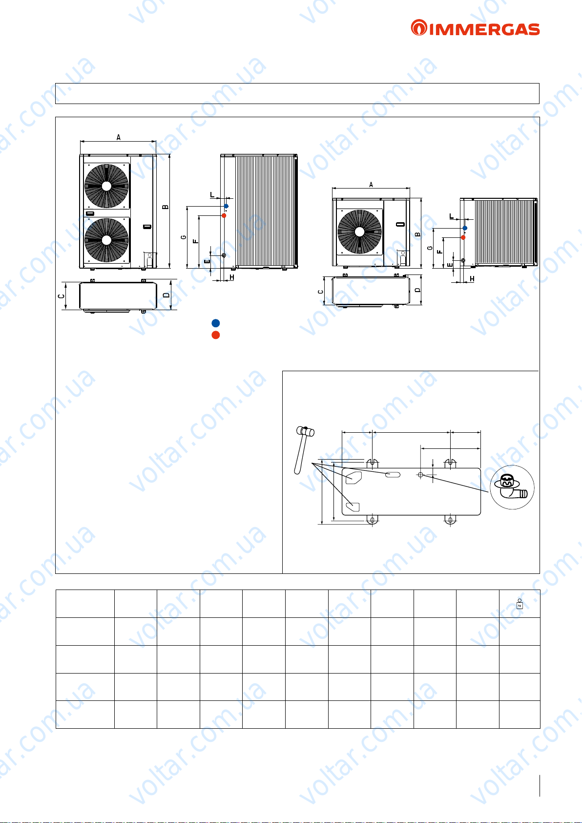
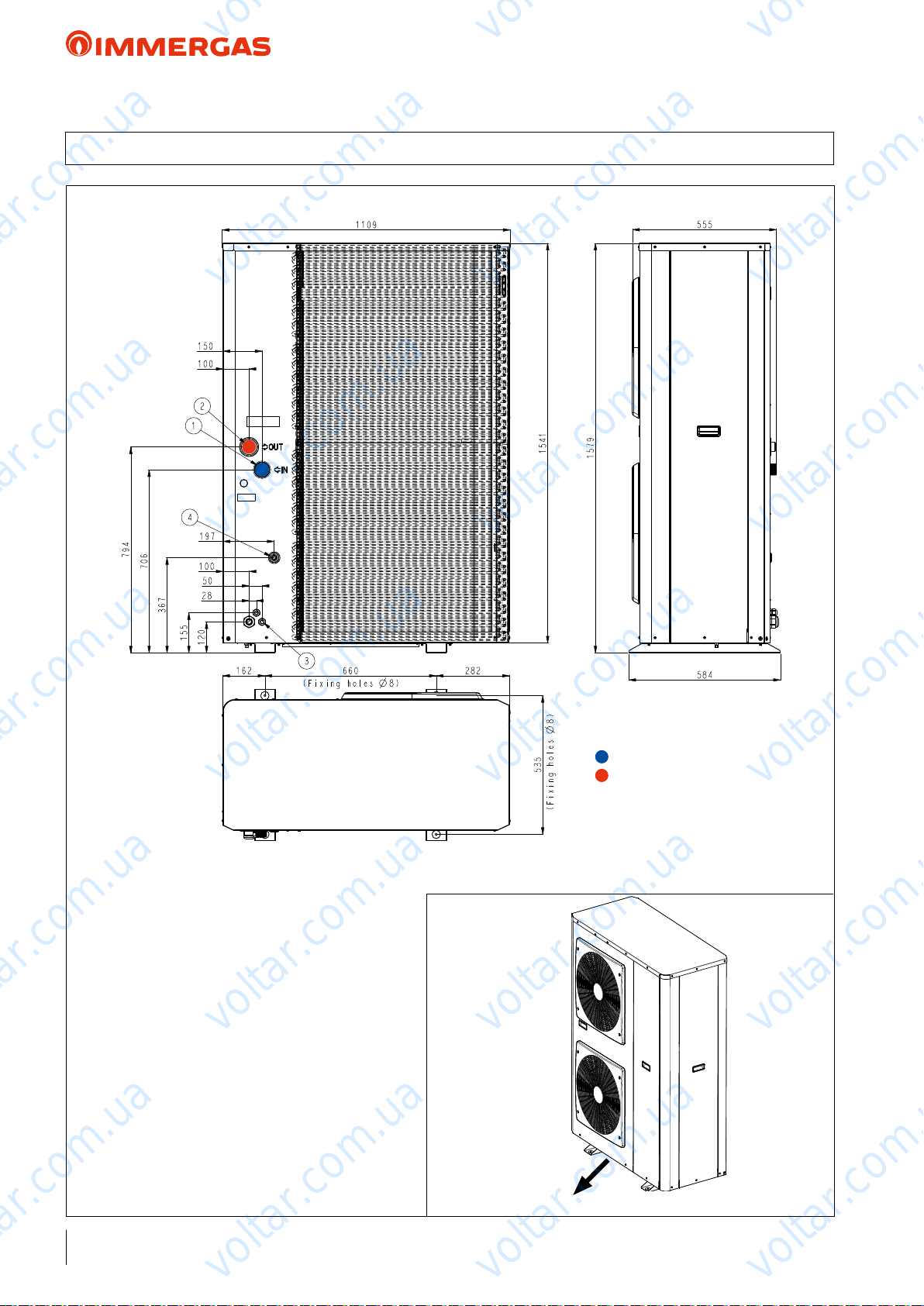
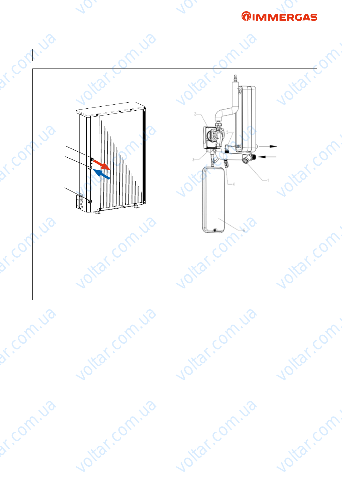
6 AUDAX TOP 6 8 12 16 ErP DIMENSIONS AND CONNECTIONS
voltar.com.ua
voltar.com.ua
System return = 1"M
voltar.com.ua
Condensate drain pipe and pre-cut holes in the
base. If draining is carried out through the drain pipe,
connect the drain tting (A) supplied, and use the
drain pipe (internal diameter: 16 mm) available on the
market. In the event of installation in very cold zones
or zones subject to heavy snow where the condensate
drain pipe can freeze, check the draining capacity of
the pipe. Draining capacity increases when the pre-cut
holes at the base, which collect condensate, are open
(open the pre-cut holes outwards with the aid of a
hammer with smooth edges).
N.B.: e gure on the side shows the measurements
to use to secure the machine (600 x 363). You must
insert the vibration-dampening devices supplied with
the product between AUDAX TOP ErP and the
support base.
voltar.com.ua
System ow = 1"M
voltar.com.ua
voltar.com.ua
600 051051
37
B
voltar.com.ua
363
400
voltar.com.ua
voltar.com.ua
430
voltar.com.ua
A
AUDAX TOP
ErP
6 kW
single phase
8 kW
single phase
12 kW
single phase
16 kW
three phase
A B C D E F G H L
908 821 326 350 87 356 466 40 60 61
voltar.com.ua
908 821 326 350 87 356 466 40 60 69
908 1363 326 350 174 640 750 44 69 104
908 1363 326 350 174 640 750 44 69 116
voltar.com.ua
voltar.com.ua
voltar.com.ua
voltar.com.ua
voltar.com.ua
21
voltar.com.ua
voltar.com.ua
AUDAX TOP ErP
6.1 AUDAX TOP 18 21 ErP DIMENSIONS AND CONNECTIONS
voltar.com.ua
voltar.com.ua
voltar.com.ua
voltar.com.ua
voltar.com.ua
voltar.com.ua
voltar.com.ua
voltar.com.ua
Slots for condensate drain. Any condensate is drained
through the slots created under the nned barrier. In
the event of installation in very cold zones or zones
subject to heavy snow where the condensate can freeze,
take the necessary precautions to prevent any frozen
zones from causing falls or accidents.
N.B.: e following gure shows the measurements
to use to secure the machine (660 x 535). You must
insert the vibration-dampening devices supplied with
the product between AUDAX TOP 18 - 21 ErP and
the support base. Immergas proposes a kit made up of
4 vibration-dampening feet (optional) code 3.027654.
voltar.com.ua
System return = 1"1/4 M *
voltar.com.ua
System ow = 1"M
*1” M Reduction standard supplied
voltar.com.ua
voltar.com.ua
voltar.com.ua
22
voltar.com.ua
voltar.com.ua
voltar.com.ua
voltar.com.ua
voltar.com.ua
AUDAX TOP ErP
7 AUDAX TOP 6 8 12 16 ErP MINIMUM INSTALLATION DISTANCES
150
voltar.com.ua
500
voltar.com.ua
200
voltar.com.ua
voltar.com.ua
150
500
voltar.com.ua
150150
300300
300
voltar.com.ua
200
150
1000
1000
voltar.com.ua
voltar.com.ua
003051
1000
voltar.com.ua
1000
voltar.com.ua
200
300
300
1000
voltar.com.ua
voltar.com.ua
300
000200510001
voltar.com.ua
voltar.com.ua
200
voltar.com.ua
23
voltar.com.ua
voltar.com.ua
voltar.com.ua
AUDAX TOP ErP
7.1 AUDAX TOP 18 21 ErP MINIMUM INSTALLATION DISTANCES
voltar.com.ua
voltar.com.ua
200
voltar.com.ua
1000
voltar.com.ua
300
5000200
200
voltar.com.ua
1000
voltar.com.ua
voltar.com.ua
voltar.com.ua
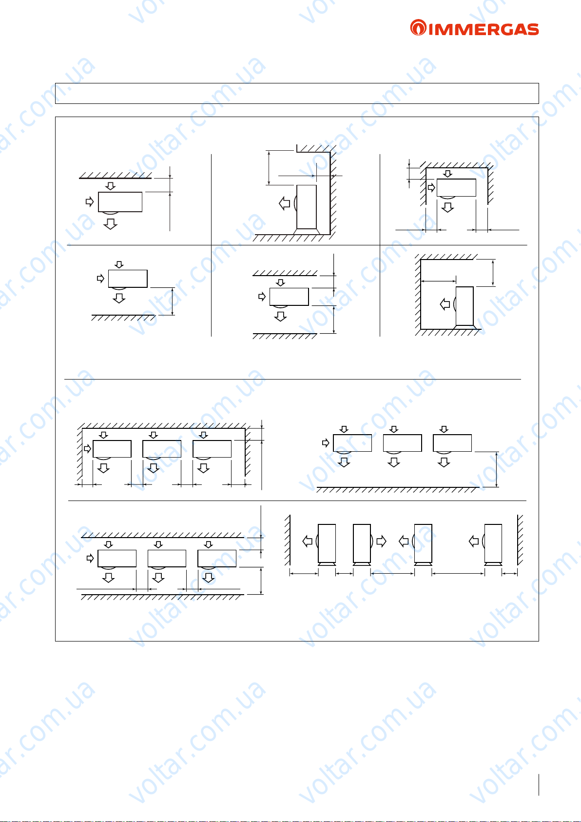
Place of installation:
e place of installation is very important and must be established by the system's designer or by a specically qualied
person, and must consider the technical requirements, standards
and laws in force.
• e unit must be installed outdoors only;
• It is recommended to avoid:
- positioning in basement windows
- obstacles or barriers that cause recirculation of exhaust air;
- places with aggressive atmospheres;
- limited spaces or anyhow in places where sound levels from
the appliance can be enhanced through reverberations or
resonance;
- positioning in corners where there is an accumulation of dust,
leaves and anything else that can reduce the appliance's eciency due to blocked passageways;
- prevent exhaust air from the device from coming into the rooms
through doors or windows, thus disturbing people;
voltar.com.ua
300
voltar.com.ua
500 500500200
• e appliances must:
- be placed on a level surface that is able to withstand its weight;
- be placed on a slab that is hard enough and which does not
transfer any vibrations to the underlying or adjacent rooms;
- use the vibration-dampening supports supplied with the
machine.
• If the unit is installed in zones subject to heavy snow, it will
voltar.com.ua
be necessary to raise the machine by at least 200 mm above
the normal level reached by the snow, or alternatively use the
wall-support bracket (optional).
• If deectors are present to protect the unit against strong winds,
these deectors must be studied so as to avoid obstructing the
normal air circulation.
voltar.com.ua
voltar.com.ua
24
voltar.com.ua
voltar.com.ua
voltar.com.ua
6
5
2
4
1
7
voltar.com.ua
voltar.com.ua
AUDAX TOP ErP
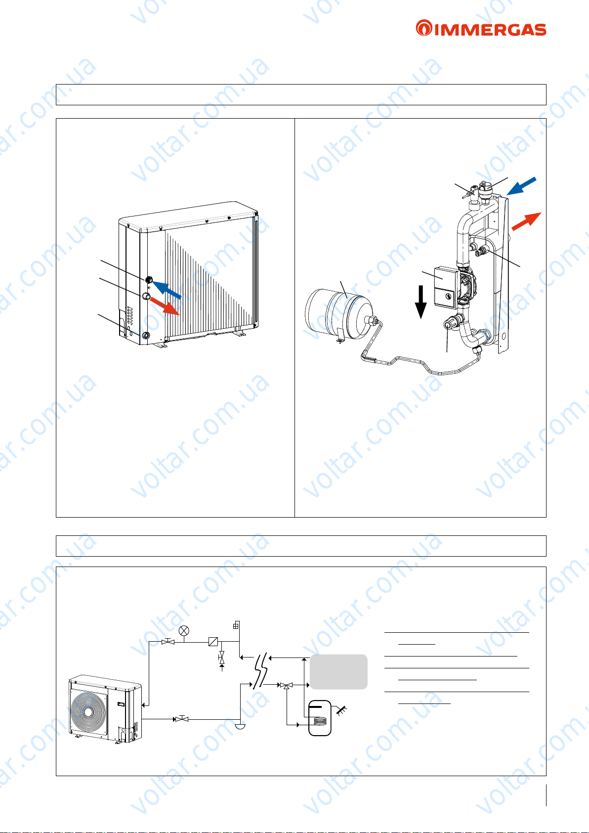
8 AUDAX TOP 6 8 ErP HYDRAULIC CIRCUIT COMPONENTS
voltar.com.ua
voltar.com.ua
1
2
3
voltar.com.ua
KEY:
1 - System return tting 1"M
2 - System ow tting 1"M
3 - Water drain
voltar.com.ua
voltar.com.ua
7
5
2
voltar.com.ua
3
KEY:
1 - Automatic air vent valve
2 - Flow switch
3 - Safety valve (outlet 1/2’)
4 - Temperature probe
5 - Circulation pump
7 - Expansion vessel
voltar.com.ua
1
voltar.com.ua
4
voltar.com.ua
voltar.com.ua
8.1 AUDAX TOP 6 8 ErP HYDRAULIC DIAGRAM
e diagram is purely indicative and not limited to the hydraulic circuit.
Also see the example on page 90-91
3
1
voltar.com.ua
1
2
6
4
3
voltar.com.ua
voltar.com.ua
7
5
8
voltar.com.ua
9
KEY:
1 - Shut-o valve
2 - Water line lters (standard)
3 - Pressure gauge (not supplied - to be
provided)
4 - Filling valve (NOT Automatic)
5 - System draining valve (in the lowest
points of the circuit)
6 - Air vent valve (in the highest points
of the circuit)
7 - 3-way valve
8 - DHW storage tank
9 - Internal utility
voltar.com.ua
25
voltar.com.ua
1
2
3
3
voltar.com.ua
voltar.com.ua
AUDAX TOP ErP
8.2 AUDAX TOP 12 16 ErP HYDRAULIC CIRCUIT COMPONENTS
7
voltar.com.ua
voltar.com.ua
1
2
3
voltar.com.ua
KEY:
1 - System return tting 1"M
2 - System ow tting 1"M
3 - Water drain
voltar.com.ua
voltar.com.ua
2
6
voltar.com.ua
KEY:
1 - Automatic air vent valve
2 - Flow switch
3 - Safety valve (outlet 1/2’)
4 - Temperature probe
5 - Circulation pump
7 - Expansion vessel
5
3
1
4
voltar.com.ua
voltar.com.ua
voltar.com.ua
voltar.com.ua
8.3 AUDAX TOP 12 16 ErP HYDRAULIC DIAGRAM
e diagram is purely indicative and not limited to the hydraulic circuit.
Also see the example on page 90-91
26
1
voltar.com.ua
1
2
6
4
3
7
5
voltar.com.ua
voltar.com.ua
9
8
voltar.com.ua
KEY:
1 - Shut-o valve
2 - Water line lters (standard)
3 - Pressure gauge (not supplied - to be
provided)
4 - Filling valve (NOT Automatic)
5 - System draining valve (in the lowest
points of the circuit)
6 - Air vent valve (in the highest points
of the circuit)
7 - 3-way valve
8 - DHW storage tank
9 - Internal utility
voltar.com.ua
voltar.com.ua
1
2
3
voltar.com.ua
voltar.com.ua
AUDAX TOP ErP
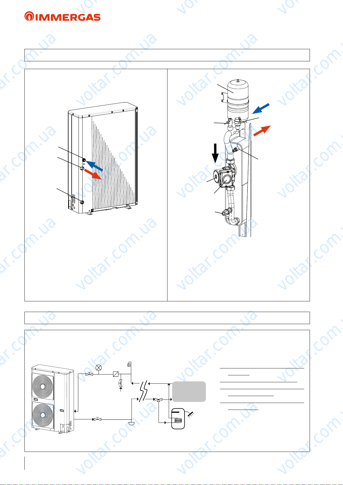
8.4 AUDAX TOP 18 21 ErP HYDRAULIC CIRCUIT COMPONENTS
voltar.com.ua
voltar.com.ua
1
2
3
voltar.com.ua
KEY:
1 - System ow tting 1''M
2 - System return tting 1"1/4 M*
3 - Water drain
*1”M Reduction standard supplied
voltar.com.ua
voltar.com.ua
OUTLET
INLET
voltar.com.ua
KEY:
1 - Mesh lter
2 - Circulation pump
3 - Safety valve
4 - Water drain valve
5 - Blade ow switch
voltar.com.ua
6 - Expansion vessel
voltar.com.ua
voltar.com.ua
voltar.com.ua
voltar.com.ua
voltar.com.ua
voltar.com.ua
voltar.com.ua
voltar.com.ua
27
voltar.com.ua
X2
10
15
20
25
30
35
40
45
50
55
60
65
70
-25 -20 -15 -10 -5 0 5 10 15 20 25 30 35
X2
Y2
AUDAX TOP 8-12-16
voltar.com.ua
voltar.com.ua
voltar.com.ua
AUDAX TOP ErP
9 AUDAX TOP 6 8 12 16 ErP OPERATING LIMITS AND ANTIFREEZE FUNCTION
Central heating
70
65
60
55
50
45
40
Y2
35
30
25
20
15
10
-25 -20 -15 -10 -5 0 5 10 15 20 25 30 35
Y1
20
18
16
14
12
10
8
6
4
2
0
-5
voltar.com.ua
voltar.com.ua
Cooling
voltar.com.ua
AUDAX TOP 6
0
105
15 20 25 30 35
voltar.com.ua
KEY:
Y2 - Flow water temperature (°C)
X2 - Outdoor air temperature (°C)
voltar.com.ua
KEY:
Y1 - Flow water temperature (°C)
voltar.com.ua
40
45
X1 - Outdoor air temperature (°C)
50
voltar.com.ua
voltar.com.ua
voltar.com.ua
X1
voltar.com.ua
NOTE: AUDAX TOP ErP is equipped with antifreeze protection up to -10 °C with supply voltage. If AUDAX TOP
ErP is installed in areas having temperatures below 0 °C, it is
recommended to provide special antifreeze systems in order to
guarantee the machine's integrity, especially the water-gas heat
exchanger, when there is a blackout.
For example, insert top quality, non-hazardous antifreeze liquid
into the heating system. In this case, the instructions of the
manufacturer of this liquid must be followed scrupulously re-
28
voltar.com.ua
voltar.com.ua
garding the percentage necessary with respect to the minimum
temperature at which the system must be kept.
An aqueous solution must be made with potential pollution class
of water 2 (EN 1717:2002).
With no supply voltage and if no antifreeze liquid has been
inserted, you must drain the water from the machine.
Avoid using automatic lling systems.
voltar.com.ua
voltar.com.ua
voltar.com.ua
10
15
20
25
30
35
40
45
50
55
60
65
70
-25 -20 -15 -10 -5 0 5 10 15 20 25 30 35
X2
Y2
AUDAX 18 TOP ErP
AUDAX 21 TOP ErP
voltar.com.ua
voltar.com.ua
voltar.com.ua
AUDAX TOP ErP
9.1 AUDAX TOP 18 21 ErP OPERATING LIMITS AND ANTIFREEZE FUNCTION
Central heating
70
65
60
55
50
45
40
Y2
35
30
25
20
15
10
-25 -20 -15 -10 -5 0 5 10 15 20 25 30 35
Y1
20
18
16
14
12
10
8
6
4
2
0
-5
0
voltar.com.ua
voltar.com.ua
Cooling
AUDAX 18 TOP ErP
AUDAX 21 TOP ErP
X2
voltar.com.ua
105
15 20 25 30 35
X1
voltar.com.ua
KEY:
Y2 - Flow water temperature (°C)
X2 - Outdoor air temperature (°C)
voltar.com.ua
KEY:
Y1 - Flow water temperature (°C)
X1 - Outdoor air temperature (°C)
voltar.com.ua
40
50
45
voltar.com.ua
voltar.com.ua
voltar.com.ua
NOTE: AUDAX TOP 18-21 ErP is equipped with antifreeze
protection comprising an electrical resistance to protect the plate
exchanger which is the most critical component with regard to
freezing. When the electrical resistance activates so does the
pump inside the AUDAX TOP 18-21 ErP, in this way, with
power supply voltage, the machine is protected up to -10°C.
If AUDAX TOP 18-21 ErP is installed in areas having temperatures below 0 °C, it is recommended to provide special antifreeze
systems in order to guarantee the machine's integrity, especially
the water-gas heat exchanger, when there is a blackout.
For example, insert top quality, non-hazardous antifreeze liquid
into the heating system.
voltar.com.ua
voltar.com.ua
In this case, the instructions of the manufacturer of this liquid
must be followed scrupulously regarding the percentage necessary
voltar.com.ua
with respect to the minimum temperature at which the system
must be kept.
An aqueous solution must be made with potential pollution class
of water 2 (EN 1717:2002).
With no supply voltage and if no antifreeze liquid has been
inserted, you must drain the water from the machine.
Avoid using automatic lling systems.
voltar.com.ua
voltar.com.ua
29
voltar.com.ua
voltar.com.ua
voltar.com.ua
AUDAX TOP 6 ErP
10 AUDAX TOP 6 ErP TECHNICAL DATA
Central heating circuit
Power in CH mode with water set at 35 °C
Power in CH mode with water set at 45 °C
Power in CH mode with water set at 55 °C
CH mode COP with water set at 35 °C
CH mode COP with water set at 45 °C
CH mode COP with water set at 55 °C
Min/max heat power with water set at 35 °C
Min/max heat power with water set at 45 °C
Min/max heat power with water set at 55 °C
Flow temperature range °C 20 / 60
Outdoor temperature heating operation limits °C -20 / 30
voltar.com.ua
(1)
kW 5.76
(2)
kW 5.76
(3)
kW 5.43
(1)
4.28
(2)
3.05
(3)
2.77
(1)
kW 1.08 / 6.14
(2)
kW 1.06 / 6.04
(3)
kW 1.02 / 5.58
voltar.com.ua
voltar.com.ua
voltar.com.ua
Cooling circuit
Power in cooling mode with water set at 18 °C
Power in cooling mode with water set at 7 °C
Cooling mode EER with water set at 18 °C
Cooling mode EER with water set at 7 °C
Min/max cooling capacity with water set at 18 °C
Min/max cooling capacity with water set at 7 °C
Flow temperature range °C 4 / 18
Outdoor temperature Cooling operation limits °C 5 / 46
General data
Max system operating pressure bar 3
Head available on the system with 1500 l/h flow rate kPa (m H2O) 40 (4.08)
Expansion vessel capacity l 2
Water circuit content l 1.0
C.H. sound power level dB(A) 62
Appliance electric protection rating IP X4
Electric supply voltage V - Hz 230 - 50
Permitted voltage range V 207 - 253
Maximum absorbed power W 2000
Maximum absorbed current A 11
Fuse inserted A 16 - Type B
Refrigerant fluid load (R410A)* g 1350
Heat Pump weight kg 61
voltar.com.ua
voltar.com.ua
voltar.com.ua
(1)
kW 7.04
(2)
kW 4.73
(1)
(2)
(1)
kW 1.20 / 7.49
(2)
voltar.com.ua
kW 0.73 / 5.33
voltar.com.ua
voltar.com.ua
voltar.com.ua
3.70
3.00
voltar.com.ua
voltar.com.ua
* Hermetically sealed system.
THE REPORTED DATA REFERS TO THE FOLLOWING CONDITIONS (in compliance with EN 14511)
ROOM C.H. MODE (°C) COOLING MODE (°C)
Room Antifreeze WATER (F/R)
Room Antifreeze WATER (F/R)
Room Antifreeze WATER (F/R)
30
(1)
- AIR (db/wb) 35/30 - 7/6 18/23 - 35 (db)
(2)
- AIR (db/wb) 45/40 - 7/6 7/12 - 35 (db)
(3)
- AIR (db/wb) 55/47 - 7/6
voltar.com.ua
voltar.com.ua
:
voltar.com.ua
 Loading...