

Page 1
Instruction and
*1.039359ENG*
recommendation booklet
IE
AUDAX PRO
5 - 8 - 10
Page 2

Page 3
Dear Customer,
Our compliments for having chosen a top-quality Immergas product, able to assure well-being and safety for a long period of time. As an Immergas customer
you can also count on a qualied aer-sales service, prepared and updated to guarantee constant eciency of your heat pump. Read the following pages
carefully: you will be able to draw useful suggestions regarding the correct use of the appliance. By respecting these suggestions, you will no doubt be satised
with your Immergas product.
For assistance and scheduled maintenance, contact Authorised Immergas Aer-Sales centres: they have original spare parts and are specically trained directly
by the manufacturer.
General recommendations
All Immergas products are protected with suitable transport packaging.
e material must be stored in dry environments protected from bad weather.
e instruction book is an integral and essential part of the product and must also be given to the new user in the case of transfer or succession of ownership.
It must be stored with care and consulted carefully, as all of the warnings provide important safety indications for installation, use and maintenance stages.
is instruction manual provides technical information for installing the Immergas pack. As for the other issues related to pack installation (e.g. safety in the
work site, environment protection, injury prevention), it is necessary to comply with the provisions specied in the regulations in force and good practice rules.
In compliance with the legislation in force, the systems must be designed by qualied professionals, within the dimensional limits established by the Law.
Installation and maintenance must be performed in compliance with the regulations in force, according to the manufacturer's instructions and by professionally
qualied sta, intending sta with specic technical skills in the plant sector, as envisioned by the Law.
Improper installation or assembly of the Immergas appliance and/or components, accessories, kit and devices can cause unexpected problems for people, animals
and objects. Read the instructions provided with the product carefully to ensure proper installation.
Maintenance must be carried out by skilled technical sta. e Immergas Authorised Aer-sales Service represents a guarantee of qualications and
professionalism.
e appliance must only be destined for the use for which it has been expressly declared. Any other use will be considered improper and therefore potentially
dangerous.
If errors occur during installation, operation and maintenance, due to non-compliance with technical laws in force, standards or instructions contained in
this book (or however supplied by the manufacturer), the manufacturer is excluded from any contractual and extra-contractual liability for any damages and
the appliance warranty is invalidated.
For further information regarding legislative and statutory provisions relative to the installation of heat pumps, consult the Immergas site at the following
address: www.immergas.com
CE DECLARATION OF CONFORMITY
For the purpose and eects of the CE 2004/108 ''Electromagnetic Compatibility'' and CE 2006/95 Low Voltage Directives.
e Manufacturer: Immergas S.p.A. v. Cisa Ligure n° 95 42041 Brescello (RE)
DECLARES THAT: Immergas packs model:
Audax Pro 5 - 8 - 10
complies with the same European Community Directives
Signature:
Mauro Guareschi
Research & Development Director
Immergas S.p.A. declines all liability due to printing or transcription errors, reserving the right to make any modications to its technical and commercial
documents without prior notice.
Page 4

INDEX
1 Safety precautions ...............................................5
1.1 Hazard. ..........................................................5
2 Unit specications. .............................................6
2.1 Main dimensions..........................................6
2.2 Outdoor unit specications. ....................... 6
3 Unit installation. .................................................7
3.1 Selecting the installation position of the
outdoor unit. ........................................................7
3.2 Locations where the unit cannot be
installed. ...............................................................7
3.3 Minimum installation distances for
individual units. .................................................. 8
3.4 Minimum installation distances for more
than one unit. ......................................................8
3.5 Installing the outdoor unit. ...............................9
3.6 Outdoor unit mount structure. .................. 9
3.7 Drainage. .....................................................10
3.8 Installing the unit in harsh climates. .......11
4 Electrical connections. ..................................... 12
4.1 General connection conguration. ..........12
4.2 Power cable features. .................................12
4.3 Connection features between indoor and
outdoor units (commonly used). ....................12
4.4 Terminal board features. ........................... 13
4.5 Supply voltage cable connection. .............14
5 Installing the chiller lines. ................................15
5.1 Chiller line geometric limits and
installation examples. .......................................15
5.2 Pipe cutting and aring ............................. 16
5.3 Selecting chiller line insulation. ...............17
5.4 Insulating the chiller lines. ........................17
5.5 Welding the pipes. ...................................... 17
5.6 Using Nitrogen. ..........................................17
5.7 Pressure testing and leak check. ............... 18
5.8 Putting under drying vacuum. ................. 19
5.9 Topping up the coolant load. .................... 20
5.10 Adding coolant. ................................................. 20
5.11 Putting in the coolant. ...................................... 20
5.12 Important information on the coolant used .20
5.13 Topping up the load. .........................................21
5.14 Service valve ...................................................... 21
6 Checking the earthing connection ................. 22
7 Micro-switch setting and key function ..........23
7.1 Operating Test. ........................................... 23
7.2 Data display mode ..................................... 24
7.3 Micro-switch setting. ................................. 25
8 Pump down procedure. ....................................26
8.1 Purpose of pump down. ............................ 26
8.2 Precautions to take before performing
pump down. .......................................................26
8.3 Precautions to take before performing
pump down. .......................................................26
8.4 Transferring the coolant into an external
tank before performing pump down. .............26
8.5 Recovering large quantities of coolant. ...27
9 Completing installation. ..................................28
9.1 Checks at the end of installation. ............. 28
9.2 Final checks and operating test ................ 28
10 Yearly unit check and maintenance. ............... 29
11 Troubleshooting. ............................................... 30
11.1 Fault codes. ................................................30
Page 5
SAFETY
1
PRECAUTIONS
e following listed precautions must be taken
scrupulously, as they are essential in ensuring the
integrity of Immergas products.
HAZARD:
- Before servicing or accessing the inner parts,
the Air-Water Heat Pump supply voltage must
be disconnected.
- Only qualied personnel must do the installation and operating test.
- To prevent serious damage to the system and
serious accidents to users, all the precautions
and suggestions in this manual must absolutely
be taken.
1.1 HAZARD.
- This manual must be read carefully before
installation and then kept in a safe place, where
it can easily be found for future needs.
- For his/her own safety, the installer is required
to carefully read all the instructions contained
in this manual.
- e user installation and instructions manual
must be given to the user to keep in a safe place,
where it can be accessed for future needs or in
the event it needs to be handed over to a new
user following sale of the heat pump or of the
building in which it is installed.
- is manual explains the installation methods
of an Immergas Water-Air heat pump system.
Using unapproved components and/or different types of control systems automatically
invalidates any form of Warranty provided by
the manufacturer. In fact, the manufacturer
cannot be held liable for damages caused by
changes or methods of use that it did not previously authorise.
- This unit is compliant with the dictates of
the European Union Low Voltage Directive
(2006/98/CE) and Electromagnetic Compatibility Directive (2004/108/CEE).
- e manufacturer shall not be held liable for
any damage caused by changes that were not
previously authorised in writing or by errors
in connecting the hydraulic and/or electrical
lines. Failure to follow these instructions and/or
using the unit out of the limits in the "Operating
Limits" table automatically invalidates any form
of Warranty provided by the manufacturer.
- e warranty shall be automatically invalidated
in the event even just one of these instructions
was not followed and the unit was made to
operate outside the Operating Field (Central
heating: from -25 to 35°C/Cooling: from 10 to
45°C) shown in the Unit Specications on page
5 of this manual.
- e unit must not be used if it is damaged or
shows signs of faults; for example, excessive
noise or a burning smell.
- To prevent electrical shock, res and/or accidents, if the unit gives o smoke, the power
cable overheats and/or is damaged, and/or the
unit becomes very noisy, it is of fundamental
importance to open the protection switch and
contact the Immergas Customer Assistance.
- e unit, its electrical, hydraulic and refrigerant
connections, as well as its protections must be
regularly inspected. All these inspection operations must only be done by qualied personnel.
- e unit must be kept out of the reach of children, as it contains live electrical components
and moving parts.
- e unit must not be repaired, moved and/or
reinstalled by unauthorised personnel, as to do
so may cause damage to the unit and/or cause
electrical shock and/or res.
- ere must be no containers containing uids
or other objects on the unit.
- All the materials used to produce and package
the air-water heat pump are recyclable.
- e packaging materials and the remote control
(optional) batteries, when exhausted, must
be disposed of in compliance with the local
standards in force.
- At the end of its life cycle, the air-water heat
pump, which is special waste and contains
coolant, must be disposed of by bringing it
to an authorised centre or returning it to the
dealer where it was purchased.
- To prevent the risk of injury from contact with
the edges of the components, work gloves must
be worn when unpacking, handling, installing
and servicing the unit.
- The inner components (hydraulic pipes,
coolant pipes, heat exchangers, etc.) must not
be touched with bare hands when the unit is
operating. If they must be touched, the unit
must rst be switched o, waiting the amount
of time necessary for it to cool down and, in
any case, wearing protective gloves.
- In the event of coolant leaks, do not touch the
leaking coolant to avoid serious injury.
- If the heat pump is installed in a closed room,
any necessary forced ventilation devices must
be provided for. ey must be the proper size
so that, in the event of leaks, the level of coolant
in the air cannot exceed the allowed limits.
- Otherwise, the people in the room under these
circumstances would be subjected to serious
risks of suocation, with even fatal eects.
- e packaging material must be disposed of
safely. It may contain nails or pieces of wood
that could injure people.
- Upon receiving the machine, it must be inspected for any damages during transport. Should
such damages be found, it MUST NOT BE
INSTALLED and the damages found must be
immediately communicated in writing to the
courier or the dealer (in the event the unit was
picked up at a dealer).
- e unit must be installed respecting the spaces
indicated in the Installation Manual in order to
make it possible to access both sides of it and
carry out maintenance operations. Should it
be installed not respecting the procedures indicated in this Manual, any expenses due to the
need to use ladders, scaolding or other raised
systems for any warranty operations shall NOT
be considered covered by the warranty itself
and, therefore, shall be entirely charged to the
Customer.
- The supply voltage line must have all the
features required by the standards in force
regarding the installation site.
- Make sure the supply voltage mains voltage
and frequency are compatible with what the
unit requires and that the system has enough
power available to supply the unit and all the
other electrical utilities it supplies. Also make
sure that all the safety switches of this system
are of the proper dimension.
- Make sure that the entire electrical system
(cables, conductor cross-sections, protections,
etc.) are compliant with the standards in force
at the installation site and with the instructions contained in the wiring diagram. All
the connections must also be compliant with
the dictates of the local standards regarding
air-water heat pump installation. Devices that
can be disconnected from the electrical mains
must not be in overvoltage conditions.
- e earthing connection must not be done on
water or gas pipes, lightning protection systems
or telephone/intercom lines as, otherwise, there
would be serious risks of electrocution and/or
res.
- Both a circuit breaker switch and a safety differential switch must be installed, both with
a capacity compliant with the dictates of the
pertinent local standards in force.
- Otherwise, there would be serious risks of
electrocution and/or res.
- Defrost water must be able to drain normally
from the unit even when the outdoor temperature is very low. Ice plugs must not be
allowed to form on this line. Otherwise, the
resulting water may not be able to drain out of
the unit, causing large chunks of ice to form,
which could, in turn, stop the unit itself from
operating.
- e power cable and the communication cable
between the indoor and outdoor unit must run
at least 1 m away from any electrical devices.
- e unit must be protected from rodents and
other small animals. If allowed to access the
unit, such animals could cause malfunctions
and/or cause smoke emissions or res. e user
must also be given clear instructions to keep the
entire area around the unit clean and tidy.
55
Page 6
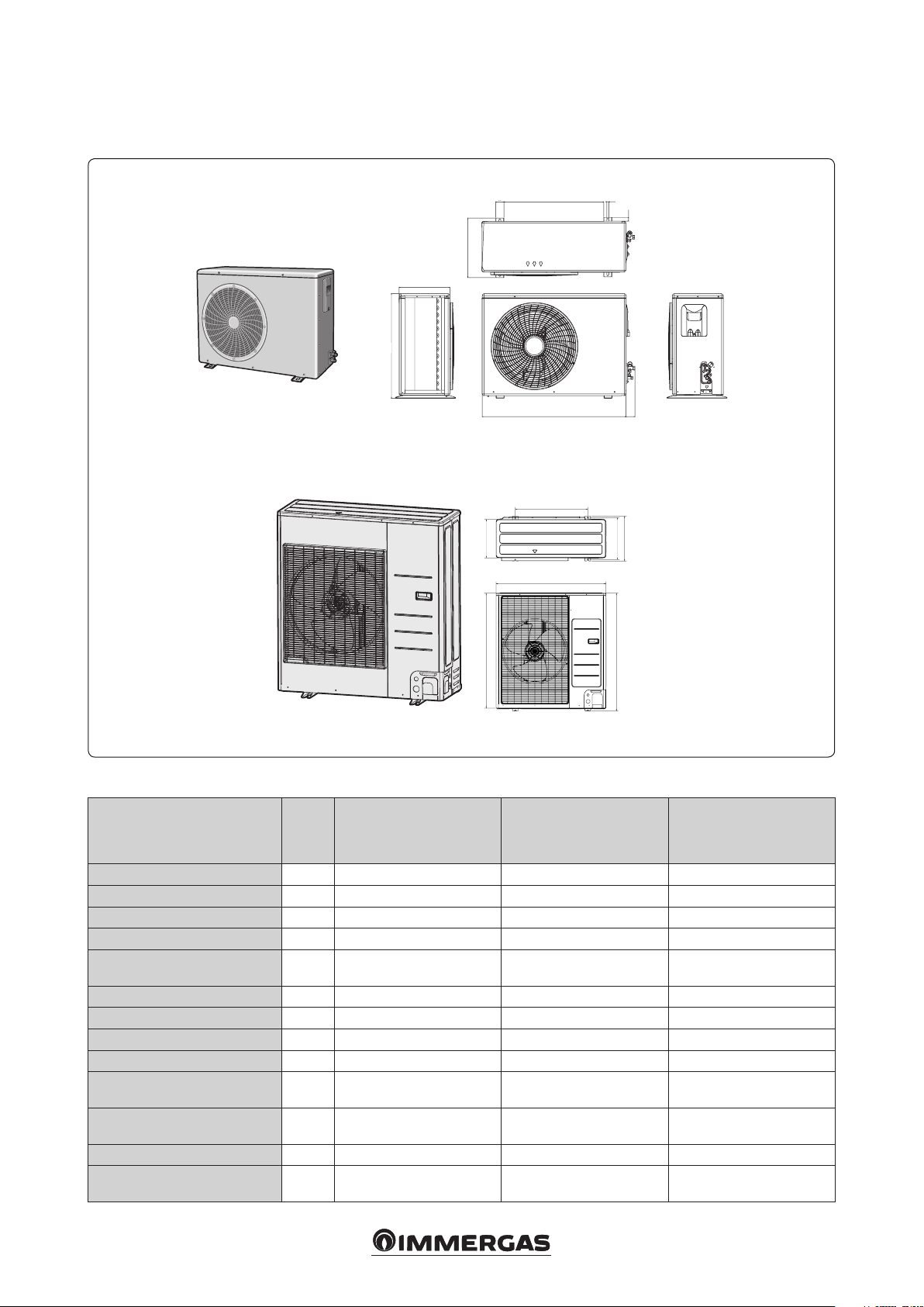
UNIT SPECIFICATIONS.
528
537
675
2
2.1 MAIN DIMENSIONS.
Audax Pro 5
Audax Pro 8 and 10
638
310
364
330973
61050
620
940
880
12
360
23
54.1
384
998
2-2
2.2 OUTDOOR UNIT SPECIFICATIONS.
Unit of
Typ e
Power Supply - 220 ~ 240 V AC / 1 F / 50 Hz 220 ~ 240 V AC / 1 F / 50 Hz 220 ~ 240 V AC / 1 F / 50 Hz
Compressor - Rotary inverter Rotary inverter Rotary inverter
Maximum input W 3200 4200 5100
Condenser - Ø 7, L 906 Ø 8, FP 1.5, L 950 Ø 8, FP 1.5, L 950
Motor fan -
Coolant load kg 1.2 2.0 2.0
Chiller line section - liquid phase 6.35 9.52 9.52
Chiller line section - gaseous phase 15.88 15.88 15.88
Sound power level dBA 62 66 66
Operating eld (central heating /
cooling)
Water output temperature °C
Weight (net / gross) kg 47.5 / 52.5 74.0 / 82.0 74.0 / 82.0
Dimensions (L x H x D, overall
clearance)
meas-
ure-
ment
°C - 20 ~ 35 / 10 ~ 46 - 20 ~ 35 / 10 ~ 46 - 20 ~ 35 / 10 ~ 46
mm 880 x 638 x 310 940 x 998 x 330 940 x 998 x 330
Audax Pro 5 Audax Pro 8 Audax Pro 10
Helicoidal, Ø420.3 with 3
blades, inverter BLDC
Cooling: 5 ~ 25
Central heating: 25 ~ 55
Helicoidal, Ø420.3 with 3
blades, inverter BLDC
Cooling: 5 ~ 25
Central heating: 25 ~ 55
Helicoidal, Ø420.3 with 3
blades, inverter BLDC
Central heating: 25 ~ 55
Cooling: 5 ~ 25
66
Page 7
UNIT INSTALLATION.
3
3.1 SELECTING THE INSTALLATION
POSITION OF THE OUTDOOR
UNIT.
e installation position must be identied in
agreement with the user and keeping the following in mind:
- e unit must not be installed upside down or
on its side, otherwise it would undergo serious damages because compressor lubrication
would be jeopardised, as the oil would spill
into the coolant circuit.
- e unit must be installed in a dry, ventilated
position but protected from sunlight and strong
winds.
- e space around the unit must be kept clean
and clear of any obstacles.
- e installation position must be such that the
noise from the unit and the air it discharges are
not of disturbance to anyone.
- e unit must be installed in a position in
which the pipes and cables can easily be connected.
- e installation position must have a stable, at
surface that can support the weight of the unit
without generating and/or amplifying noises
and vibrations.
- e unit must be installed in a position that
allows the air to be discharged outdoors with
no impediments.
- ere must be no trees near the installation
position and it must not be accessible to animals as, otherwise, the unit could have trouble
operating.
- All around the unit, there must be the space
necessary for air to circulate and there must
be no stereo, radio, television, computer, etc.
systems.
- If installed near the shoreline, the unit must not
be directly exposed to salinity (see g.3-1).
3.2 LOCATIONS WHERE THE UNIT
CANNOT BE INSTALLED.
e unit must not be installed in sites where:
- ere are mineral oils or arsenic acids. Otherwise, the parts of the unit in resin could burn,
damaging it. e coolant-air exchanger could
also be damaged, which would have a very
negative impact on unit operation.
- ere are corrosive, sulphuric or acid gases like,
for example, those from chimneys or exhaust
air vents. Otherwise, the unit's copper pipes
could corrode, allowing the coolant to escape.
- ere is the risk of ammable gas leaks or there
are carbon bres or ammable dust. Petrol and/
or solvents are handled.
Attention: when the unit is installed in areas
exposed to snowfall or excessively harsh
temperatures (aka in areas with typically low
temperatures and high humidity - that is, with
temperatures below -7°C and relative humidity
above 85%), ice plugs could form in the defrosting water drainage outlets.
Any build-up of ice that forms on the unit can
damage it.
Attention: e unit must be installed respect-
ing local electrical standards.
Should the weight of the unit exceed 60 kg,
wall-mounted installation is not recommendable as it is preferable to install it on the ground
for safety reasons.
- If installed wall-mounted, the unit must be
securely attached to the structure supporting it.
- Water or condensate produced by the unit must
be able to drain out evenly and safely.
- Local regulations permitting, if it should be
installed on a road, the unit must be raised at
least 2 m from the pavement so as to prevent the
air it discharges from disturbing passers-by (to
be certain, consult the standard of town where
it is installed).
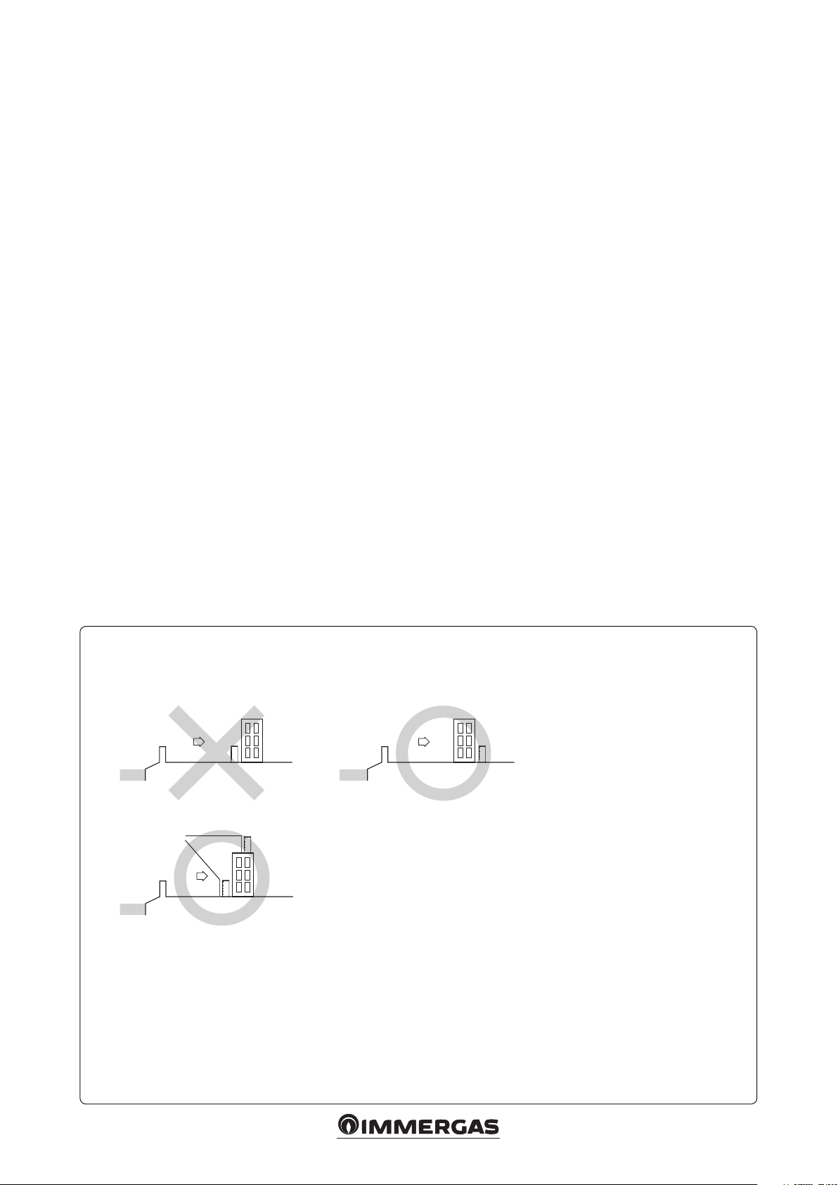
In the event of installation near the shoreline, as an alternative the unit can be positioned in a place where there is an obstacle (a
building, a wall, etc.) separating it from the sea breeze that could cover it in salinity.
Outdoor
Sea breeze
Sea
- If installed on the shoreline, the unit must always be protected by at least a wall.
Protective wall
Sea breeze
Sea
- e unit must be installed in a position in which the condensate it generates and the water resulting from defrosting can drain
out normally.
Do not hesitate to contact Immergas Customer Assistance if you are unable to satisfy all the above conditions. e coolant-air
exchanger must always be kept free of sand and sea water.
unit
Outdoor
unit
Sea breeze
Sea
e wall must be built with heavy materials like, for example,
concrete blocks and be able to stop the sea breeze. e height and
width of the protective wall must be at least 1.5 times the width
of the unit, which must be positioned at least 700 mm away from
the wall itself so as not to impede air expulsion.
Outdoor
unit
3-1
77
Page 8
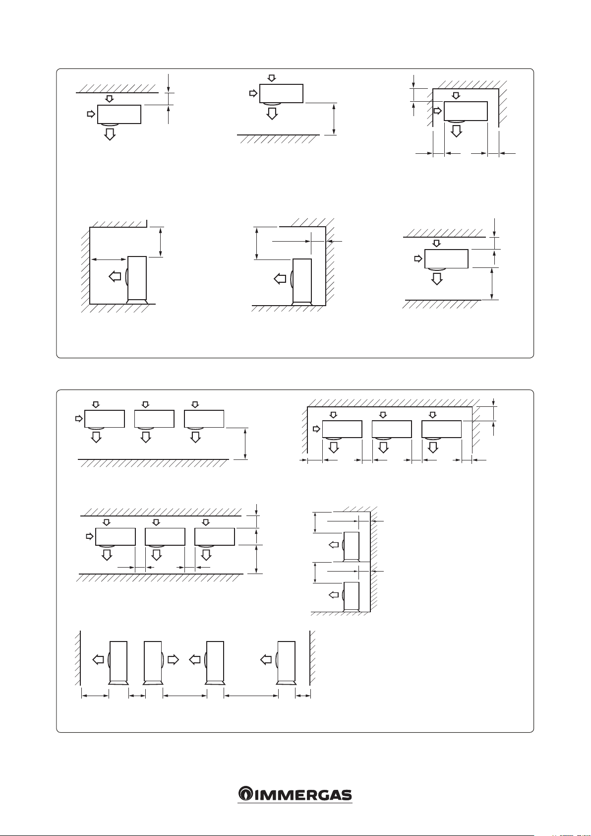
3.3 MINIMUM INSTALLATION DISTANCES FOR INDIVIDUAL UNITS.
300 min.
With the back side of the unit
facing a wall
2,000 min
1,500 min.
With the top and front sides of the
unit facing a wall
3.4 MINIMUM INSTALLATION DISTANCES FOR MORE THAN ONE UNIT.
With the front side of the unit
facing a wall
300 min.
600 min.
With the top and back sides of the
unit facing a wall
300 min.
1,500 min.
300 min. 600 min.
With three sides of the unit facing
a wall
300 min.
1,500 min.
With the front and back sides of
the unit facing a wall
3-2
1500 min.
the front side of the unit facing a wall
600 min.
With the front and back sides of the unit facing a wall
1500 min. 600 min. 3000 min. 300 min.3000 min.
With the units facing each other and with the front and back sides of the end
units facing a wall.
600 min.
300 min. 600 min. 600 min. 600 min.
With three sides of the unit facing a wall
300 min.1500 min.
500 min.
500 min.
300 min.
300 min.
300 min.
With the top and front sides of the
unit facing a wall
3-3
Attention: the spaces shown must be le free to allow air to circulate and to ensure accessibility for repairs or maintenance on every side of the units.
In fact, it must be possible to disassemble all the unit components under the utmost safety conditions (both for objects and for people).
88
Page 9
620
940
328
344
384
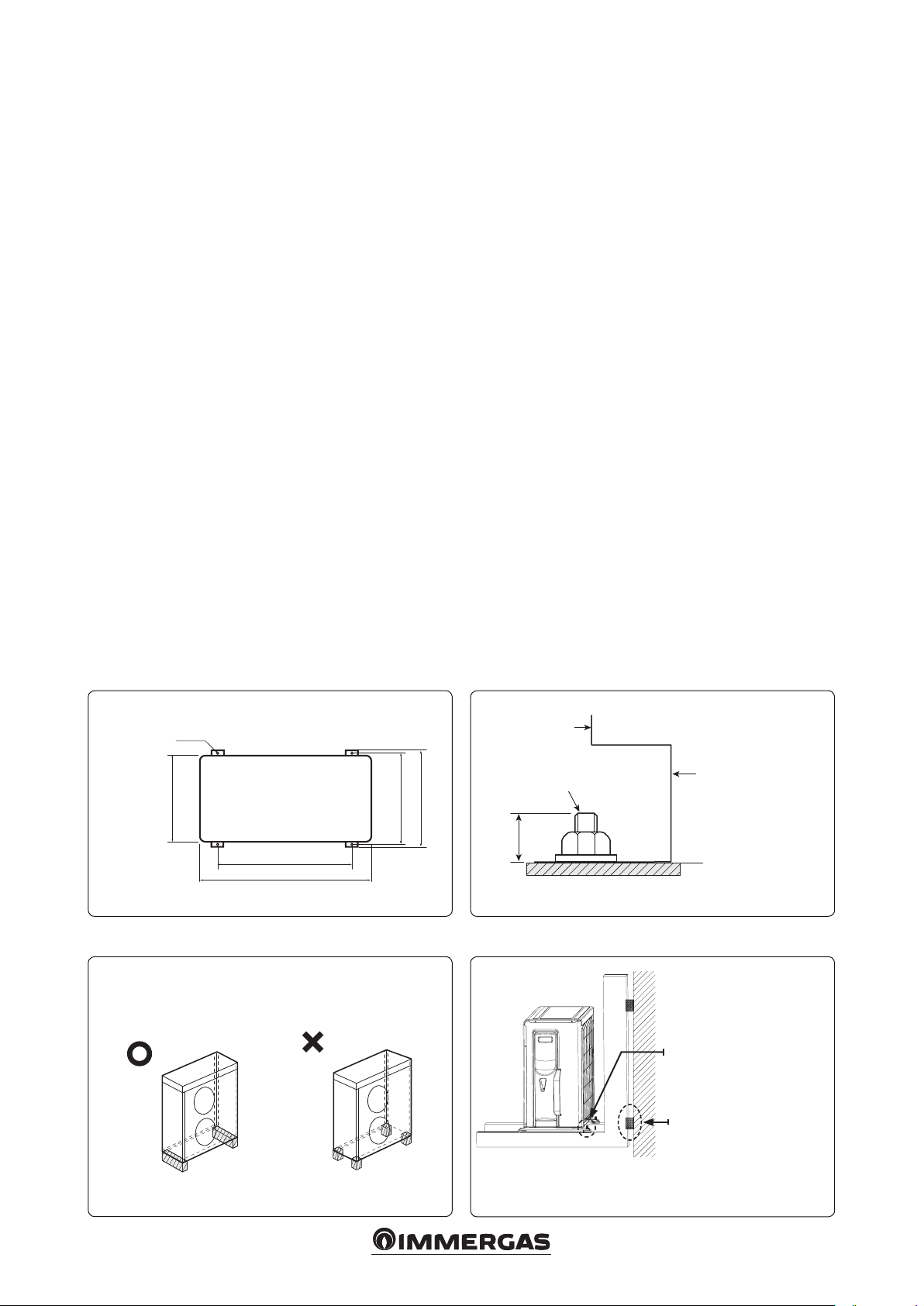
3.5 INSTALLING THE OUTDOOR UNIT.
20mm
To prevent the noise and vibrations it could
generate from being amplied, the outdoor unit
must be installed on a rigid base. Furthermore,
should it be installed in a position that is exposed
to strong winds or wall-mounted, it must be
solidly secured to the structure supporting it
(oor or wall).
e unit must be secured at the base with anchoring screws, using the anti-vibration pads
provided (g. 3-4).
N.B.: each anchoring screw must protrude
by at least 20mm from the base in which it is
embedded.
Attention:
- It is a good idea to insert rubber washers (not
supplied) between the tightening screw nuts
and the feet on the unit, as well as between
the latter and the supporting base to prevent
corrosion.
- A draining channel must be dug all around the
base of the unit that can appropriately drain the
water and condensate produced by the unit.
- When the unit must be installed on a roof, the
resistance of said roof must rst be checked.
Install the unit without damaging the roof itself
and/or its waterproong.
3.6 OUTDOOR UNIT MOUNT
STRUCTURE.
Figures 3-5 to 3-7 illustrate the instructions to
install the condensing unit mount structure.
When the outdoor unit is installed on a mount
structure attached to a wall, you must:
- Make sure the wall can support the weight of
the support structure plus the weight of the
device;
- Install the mount structure with the least
amount of overhang possible;
- Insulate the structure with respect to the wall
by inserting rubber dowels between them to
prevent vibrations from being transmitted to
the wall.
- Attention: the machines cannot be ducted.
Hole for anchoring screw
3-4
NO
OK
OK
3-6 3-7
NO
3-5
Outdoor
Unit
Anchoring Screws
Outdoor unit mount
structure
Base surfaces
Structure designed to eliminate
the residual vibrations that
the unit could transmit to the
outdoor unit mount structure
(not supplied by Immergas).
Rubber shock absorbers (not
supplied by Immergas) selected
to eliminate the vibrations that
the mount structure could
transmit to the wall.
99
Page 10
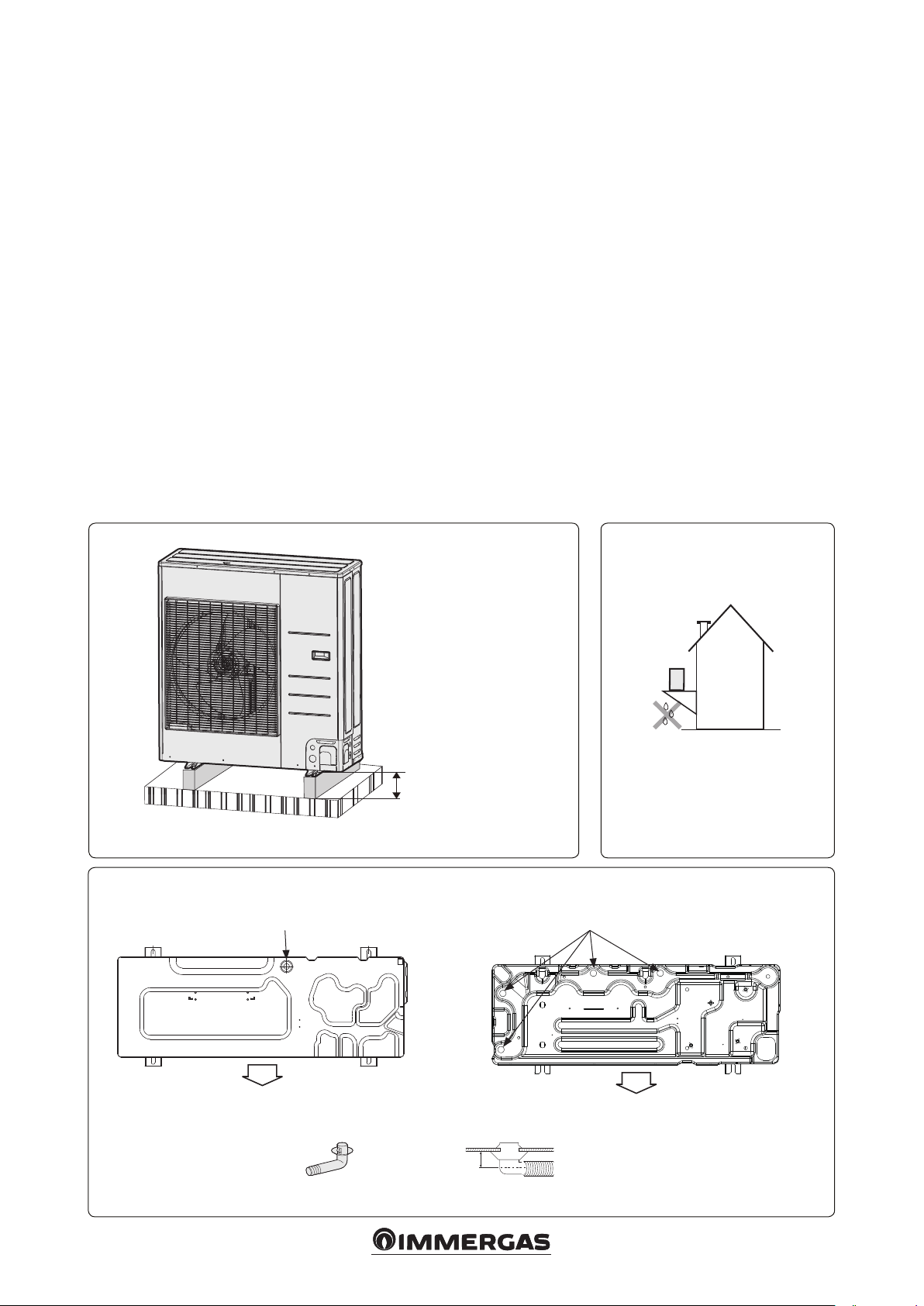
3.7 DRAINAGE.
During central heating, ice can deposit on the
outer surface of the coolant-air exchanger. To
prevent these deposits from becoming excessive,
the unit runs defrosting cycles to melt them. e
water resulting from this process is eliminated via
drainage holes to prevent it from re-solidifying
at the bottom of the unit when the outdoor
temperature is quite low.
• If, for whatever reason, this water cannot be
allowed to drain freely, you must:
- Leave a space of at least 50 mm (5 kW version)
and 100 mm (8 / 10 mm version) from the
support surface (Fig. 3-8).
- Insert the drainage tting in one of the three
drainage holes on the bottom of the unit and
plug the other three with the supplied drain
plugs.
- Connect the drainage tting to a hose that
conveys the water to the desired location.
- Prevent dust and debris from entering the
drainage hose.
Attention: if the water produced by the unit is
not properly drained, the performance of the
entire system will suer a negative impact and
the system itself could be damaged.
Warnings.
1 Dig a draining channel all around the base of
the unit that can appropriately drain the water
and condensate produced by the unit.
2 To facilitate drainage, you can install the unit
on a base of cement blocks so that it is at least
150 mm o the ground.
3 e unit must be raised at least 150 mm o the
ground to prevent it from being ooded in the
event of heavy rain.
4 If installed in a snowy area, the unit must be
raised o the ground by at least the height of
the heaviest foreseeable snowfall.
5 If wall-mounted (see gure), it is a good idea to
position a container (not supplied by Immergas) about 150 mm below the bottom of the
unit to collect and drain the condensate that
may drip from the unit.
3-8
3-10
≥ 50 mm (Audax Pro 5)
≥ 100 mm (Audax Pro 8 / 10)
3-9
Audax Pro 5 Audax Pro 8 and 10
Ø20 drainage hole (in 4 positions)Ø20 drainage hole
Air ow side
30 mm
Drainage tting (1)
Air ow side
1010
Page 11

3.8 INSTALLING THE UNIT IN HARSH
CLIMATES.
N.B.: if installing the unit in harsh climates, you
must follow all the instructions below.
- e eects of the wind can be minimised by
installing the unit with the intake side facing a
wall.
- e unit must not be installed with the intake
side against the wind.
- e eects of the wind can be further minimised by installed a deector plate facing the
unit air ow side.
- e unit must be installed in a position protected from snow falling from above. If this is
not possible, you must at least prevent the snow
from clogging the air coolant exchanger (even
by constructing a small protective roof for the
unit, if necessary (Fig. 3-11)).
- e fan in the outdoor unit will work normally
with the K7 micro-switch on "ON" to prevent
snow from accumulating in the unit. (see parag.
7.3)
- e direction the unit faces depends on the
direction of the strongest winds. As it could
overturn with strong winds, the unit must be
oriented with one of its narrower sides against
the wind.
1
2
1 - Overall protective roof.
2 - Raised base.
e base must raise the unit
from the ground by at least the
height of the heaviest foreseeable
snowfall.
3-11 3-12
Strong wind
1111
Strong wind
Air ow
Page 12

ELECTRICAL
4
CONNECTIONS.
4.1 GENERAL CONNECTION
CONFIGURATION.
OUTDOOR UNIT
SUPPLY VOLTAGE
4-1
Mono-phase
2 230Vac
conductors
OUTDOOR
UNIT
PROTECTION
SWITCHES
Mono-phase
2 230Vac
conductors
COMMUNICATION
CABLE
UNIT SUPPLY
VOLTAGE
SYSTEM INTEGRATING RE-
SISTANCE SUPPLY VOLTAGE
Mono-phase
2 230Vac
conductors
INDOOR
UNIT
DOMESTIC
HOT WATER
TANK
4.2 POWER CABLE FEATURES.
- e power cable is not supplied with the unit.
- e outdoor unit power cable must be suitable for outdoor installation and must have at
least a exible polychloroprene sheath (Code
IEC:60245 IEC 57 / CENELEC:H05RN-F)
Attention:
should the connection
cable require an extension, do not use a circular
pressure terminal. Connection cables with connections that are not to code can be the cause of
electrical shock and res.
Mono-phase.
Maximum absorbed current
(MAC) in nor-
mal operation
MAC1.25
+ Additional
Load
Outdoor
Unit
Nominal Values
Field of
Tolerable
Voltage
Hz V V V. A A A
5 kW 50 220 - 240 198 264 20 25.0 30
8 and 10
kW
50 220 - 240 198 264 22 27.5 40
4.3 CONNECTION FEATURES
BETWEEN INDOOR AND
OUTDOOR UNITS COMMONLY
USED.
Use H07RN-F or H07RN-F class cables to power
the indoor unit.
When the indoor unit is installed in a room with
a computer or internet server, you must use a
double shielded FROHH2R class cable (Aluminium tape/Polyester + Copper braid).
Supply Voltage
Supply Voltage Max./Min.(V) Connection cable
Mono-phase,
220-240V, 50Hz
±10% 0.75 ~ 1.5mm², 3 wires 0.75 ~ 1.5mm², 2 wires
Communication cable
Fuse
capacity
necessary
for the unit
1212
Page 13

4.4 TERMINAL BOARD FEATURES.
Audax Pro 5 - Supply voltage in mono-phase AC.
M4 screw supply voltage M4 screw communica-
L
N
11.4 10.1
4-2
Audax Pro 8 and 10 - Supply voltage in mono-phase AC.
Electric supply voltage
M5 screw
L
N
15 12
4-3
tion bus
10.1
11.4
M3 screw communication bus
6.7
9.7
1313
Page 14

4.5 SUPPLY VOLTAGE CABLE
CONNECTION.
Attention:
- Aer connecting it to the terminal board, the
power cable must be secured using a cable
locking terminal.
- Voltage imbalance must not exceed 2% of
nominal voltage
With use of the mono-phase safety switch (ELB).
- Otherwise, condenser duration could be
jeopardised. Should imbalance exceed 4%, the
indoor unit would stop and an error would be
signalled
- To protect them from water and possible
mechanical trauma, the power and communication cables must run through a cable duct
(with an IP protection that is compliant with
the specic application requirements).
- e power cable must be connected to a 230V
±10% / 50Hz mains, respecting L-N polarity
and the earthing connection
; this network
must have a multi-pole circuit breaker with
class III overvoltage category.
- In the event of overvoltage, all the units connected to the supply voltage line must automatically disconnect.
- e communication cable must run at least 50
mm away from the power cable.
Depending on the model, the actual
appearance of the unit may dier from the
one shown in the gure.
Electrical panel
MCCB
ELB
MCCB
Hydro Unit
4-4
Connection to the supply voltage terminal
board.
- e connection must be made aer having secured the wires to ring compression terminals.
- Only use the types of cables specied.
- For the connection, you must only use screwdrivers that can give the screws the prescribed
tightening torques.
- Should the connection be loose, voltaic arcs
could be triggered, which could, in turn,
cause res. Instead, should the connection be
excessively tightened, the terminal could be
damaged.
Tightening torques (kgfcm) for terminal board
screws:
- M4 12.0 ÷ 14.7
- M5 24.4 ÷ 29.8
Connecting the earth cable.
- Only use the types of cables specied among
the features of outdoor unit cables.
- For the earthing connection, use a type of cable
specied for the outdoor unit.
Power cable earthing connection.
- e connection method depends on the nominal voltage and the site in which the Heat Pump
is installed.
- In any case, the features of this connection must
the following:
Key:
ELB - Safety Switch
MCCB - Circuit breaker switch
L
N
clamping
Main power
cable
Earthing connection.
- e earthing connection must be done by a
specialised electrician.
- Make sure the resistance to earth is < 100 Ohm.
If there is a circuit breaker switch to interrupt
the circuit in the event of a short circuit, the
resistance to earth can be 30 ÷ 500 Ohm.
Cable
clip
Communication
cable
Fairlead
terminal
1414
Page 15

INSTALLING THE CHILLER
H1
5
LINES.
- e length of the pipes between the outdoor
and indoor units and the dierence in the pipe
lengths aer the rst junction and the drop
must not exceed the indicated limits.
- R-410A is a high pressure coolant.
- Only use pipes that are certied for chilling and
follow the installation methods below.
- Only use clean pipes with no harmful ions,
oxides, dust, traces of iron or moisture.
- Only use equipment and ttings for R-410A.
Manometric unit. Use an R-410A manometric
unit to keep foreign objects from getting into the
chiller lines and prevent reading errors.
Vacuum pump. Only a vacuum pump with a
non return valve must be used to prevent the
oil inside it from getting into the chiller circuit
when it stops. is pump must be able to create
a vacuum of up to 500 mTorr (66 Pa).
Flare nuts. Only use the flare nuts supplied
with the unit.
5.1 CHILLER LINE GEOMETRIC LIMITS
AND INSTALLATION EXAMPLES.
e maximum lengths of the chiller lines are
listed below, based on the condensing unit model
and the type of installation (g. 5-1).
A
Audax Pro 5
A ≤ 30 m ≤ 50 m
H1 ≤ 20 m ≤ 30 m
H2 ≤ 20 m ≤ 15 m
N.B.: it is recommendable to provide for a siphon
in the immediate vicinity of the condensing unit.
If the length of the chiller line is greater than
the one given in the machine pre-load, it is
recommendable to provide for a siphon halfway.
A siphon is also recommendable in the event of
installation with drops between the condensing
unit and the hydronic unit.
Audax Pro
8 and 10
H2
A
5-1
1515
Page 16

5.2 PIPE CUTTING AND FLARING
1 Make sure you have all the equipment neces-
sary: pipe cutter, deburring tool, aring tool,
clamp, etc.
2 If the pipe needs to be shortened, it must be
cut with a pipe cutter, being careful to keep the
cutting angle at 90° with the pipe axis. Figure
5-2 shows some examples of correctly and
incorrectly made cuts.
3 To prevent coolant leaks, cutting burrs must
absolutely be eliminated using a deburring tool.
Attention: during deburring, the pipe must
be facing downward to prevent shavings from
getting into it (see g. 5-3).
4 Insert the nut in the pipe, then are it according
to the features indicated in gure 5-4
5 Make sure flaring has been done properly.
Figure 5-5 shows some examples of correctly
and incorrectly done aring.
6 Align the pipes to make connection easier.
Tighten the are nut by hand at rst, then denitively, using a dynamometric key calibrated
to the torque shown in gure 5-6.
N.B.: tightening to an excessive torque can
cause coolant to leak.
Attention: any welding must be done in a
Nitrogen atmosphere.
90°
5-2 5-3
Pipe
5-4
Flare
Obliquity
Roughness
Outside diameter
[D (mm)]
Burr
Overhang
[A (mm)]
Ø 6.35 1.3 9.0
Ø 9.52 1.8 13.0
Ø 12.70 2.0 16.2
Ø 15.88 2.2 19.3
Ø 19.05 2.2 22.5
Pipe
Burr
Pipe cutter
Collar diameter
[B (mm)]
Correct Obliquity CrackingDamage to the
5-5
Lubricate with coolant oil
Indoor unit coupling
5-6
Flare nut
Pipe to connect
seal surface
Unevenness in the
thickness
External diameter (mm) Tightening torque (Nm)
Ø 6.35 12 ÷ 17
Ø 9.52 30 ÷ 35
Ø 12.70 40 ÷ 45
Ø 15.88 50 ÷ 60
Ø 19.05 60 ÷ 70
1616
Page 17

5.3 SELECTING CHILLER LINE
INSULATION.
- e gas and liquid chiller lines must be insu-
lated with materials selected based on their
respective diameters.
- Standard insulation is required at a temperature
of 30°C with 85% relative humidity. Should the
thermohygrometric conditions of the air be
harsher, you must use insulations that can be
selected from the table in gure 5-7
- Attention:
- e insulation cannot be interrupted and for
this reason, its junctions must be sealed with
adhesive to prevent moisture from getting in.
- Should the insulation be exposed to sunlight,
it must be protected by wrapping it with electrical tape or material suitable for this type of
application.
- e insulation must be laid without its thick-
ness being reduced in the bends and supports
of the pipes.
Line
Liquid
Gas
5-7
Pipe diameter
(mm)
Ø 6.35 ÷ 19.05 9 9
Ø 12.70 ÷ 19.05 13 13
Ø 6.35 13 19
Ø 9.52
Ø 12.70
Ø 15.88
Ø 19.05
5.4 INSULATING THE CHILLER LINES.
- e insulation must only be laid aer having
made sure that there are no coolant leaks on
the lines.
- Use EPDM insulation with the features described in the table in gure 5-8.
- e chiller lines, the junctions and the connections must be insulated with class "0" (zero)
material.
- Proper insulation prevents condensate from
forming on the surface of the pipes and protects
heat pump performance and the level of user
satisfaction.
- Make sure that the insulation is not broken and/
or interrupted in the pipe bends (Fig. 5-9).
Insulation thickness
Standard conditions
(Less than 30°C, RH
85%)
EPDM, NBR
19 25
High humidity condi-
tions
(Over 30°C, RH 85%)
5.5 WELDING THE PIPES.
- Make sure there is no moisture inside the pipes
- Make sure there are no foreign objects inside
the pipes.
5.6 USING NITROGEN.
1 Welding must be done in a nitrogen atmos-
phere, that is, insufflating the pipes with
nitrogen as shown in gure 5-10.
2 Should welding be done without insuating
nitrogen, flakes of rust would form inside
the pipes. In coming loose, these akes could
damage the compressor and the valves.
3 e ow of nitrogen must be controlled, cali-
brating the pressure regulator so as to obtain a
ow of at least 0.05 m3/h.
4 e valves must be protected from heat while
they are being welded.
Notes
e pre-selected
material must be able to
withstand temperatures
exceeding 120°C.
5-8
Insulation
Gas pipe
Liquid pipe
Item Unit Standard Value Notes
Density g/cm² 0.048 ÷ 0.096
Dimensional variation due to temperature changes
Moisture permeability g/cm² ≤ 0.005
ermal conductance kcal/m·h·˚C ≤ 0.032 KSL 9016-95
Moisture transpiration factor ng/(m²·s·Pa) ≤ 15 KSM 3808-03
Moisture transpiration degree {g/(m²·24h)} ≤ 15 KSA 1013-01
Formaldehyde release mg/L - KSF 3200-02
Oxygen rate % ≤ 25 ISO 4589-2-96
Clip
Indoor
Indoor
unit
unit
% ≤ -5
Insulation
Overlapped
e insulation must completely overlap the pipes
KSM 3014-01
Tap ing
Part to
weld
Nitrogen
Pressure
regulator
1/4" copper
pipe
Valve stem
5-9
5-10
1717
Page 18

5.7 PRESSURE TESTING AND LEAK
CHECK.
- To prevent foreign substances from getting into
the circuit and to ensure the essential resistance
to the pressures in play, it is fundamental that
only an R-410A manometric unit be used.
- e pressure test must only be done using dry
nitrogen.
Pressurise with dry nitrogen at 4.1 MPa via the liquid and gas pipe.
Leave everything alone for at least 24 hours to check whether the
If pressure decreases, it means there are leaks.
Maintain a pressure of at least 1.0 MPa and check for leaks again before
putting the circuit under vacuum and drying it.
Audax Pro 5 Audax Pro 8 and 10
Low pressure
pressure falls.
Manometric unit
side
High pressure side
Should the unit be pressurised with nitrogen at more than 4.1 MPa,
the pipes could be damaged. Pressing must be done using a pressure
Pressure variations that can occur aer pressurising with nitrogen must
Should pressure decrease, a foaming solution must be applied to all the
junctions to locate the leaks. Bubbles forming in the foaming solution
pinpoint the location of the leaks, which must be eliminated before
Aer having repaired any leaks, you must maintain pressure at 1.0 MPa
Low pressure side
Service
coupling
regulator.
be checked using a pressure regulator.
re-pressurising with nitrogen.
at least and check for leaks again.
Manometric unit
High pressure side
Pressure regulator
(indispensable)
Service
door
5-11
To check for leaks, you must use an approved
foaming solution. Using a solution of water and
normal soap risks damaging the are nuts or
triggering corrosive processes in the are joints.
Attention: should a coupling be disconnected,
the gas that escapes could cause injuries when
coming into contact with people. Tighten the
couplings as required to prevent these accidents.
Pressure regulator
(indispensable)
Nitrogen
Gas pipe
Service coupling
Nitrogen
1818
Page 19

5.8 PUTTING UNDER DRYING
VACUUM.
- To prevent foreign substances from getting into
the circuit and to ensure the essential resistance
to the pressures in play, it is fundamental that
only an R-410A manometric unit be used.
- Only a vacuum pump with a non return valve
must be used to prevent the oil inside it from
getting into the chiller circuit when it stops.
- Use a pump that is able to create a vacuum of
up to 500 mTorr (66 Pa).
- Completely close the service valves on the gas
and liquid side.
Attention: if pressure increases aer an hour, this
means that there is residual water inside the pipe
and/or there are leaks.
Connect the manometric unit to the
liquid and gas pipes.
Audax Pro 5 Audax Pro 8 and 10
Manometric unit
Vacuum
pump
5-12
Manometric unit
Vacuum
pump
Using the vacuum pump, put the liquid
and gas pipes under vacuum and dry
them.
Putting under vacuum and drying must
last at least 2 hours and 30 minutes.
Close the valve once pressure drops to
500 mTorr.
Pressure increases
No
Put in the coolant
Make sure the vacuum pump is equipped with a non
return valve as, otherwise, when it stops, the oil inside of
it would be sucked back into the coolant circuit.
e time necessary to put under vacuum and dry varies, as
it depends on the length and diameter of the pipes, as well as
on the outdoor air temperature. Drying and putting under
vacuum must, however, last at least 2 hours and 30 minutes.
Check the vacuum level using a vacuometer.
Check for leaks
Yes
e pressure increases due to residual
water in the pipes.
Put in dry nitrogen at a pressure of 0.05
MPa to dilute the moisture.
Put under vacuum and dry again, lowering the pressure down to 500 mTorr
(66Pa) for at least 2 hours
5-13
No
1919
Pressure increases
Yes
Page 20

5.9 TOPPING UP THE COOLANT LOAD.
Below is the default factory base load:
- Audax Pro 5: 1.2 kg
- Audax Pro 8 and 10: 2.0 kg
The top-up depends on the total length and
diameter of the pipes.
All the default factory loads are determined as
follows, depending on the standard length of
the pipes:
- Audax Pro 5: ≤ 5m
- Audax Pro 8 and 10: ≤ 15m
Should the pipes used be longer, the load must
be topped up as follows.
e top-up amount depends on the total length
of the liquid line.
(g) = {(L1 - n) x 20} + {(L2 - n) x 50}
Key:
L1 - Total length of the Ø 6.35 liquid pipe,
(m)
L2 - Total length of the Ø 9.52 liquid pipe,
(m)
n - standard pipe length, see previously
listed specic value
5.10 ADDING COOLANT.
As the outdoor unit comes already equipped with
the base load, the amount to top-up depends on
the total length and diameters of the liquid pipes.
Liquid line Ø 6.35 Ø 9.52
Top-up (g) 20 g/m 50 g/m
Calculating the amount to top-up:
(Total length (m) of the Ø 9.52 pipes) × 50 g
+ (Total length (m) of the Ø 6.35 pipes) × 20g
Example:
20 m × 50 g/m + 20 m × 20 g/m = 1,400 g
5.11 PUTTING IN THE COOLANT.
R-410A is a blend of several coolants. For this
reason, it must be put into the chiller circuit only
in its liquid phase.
e amount of coolant to put in depends on the
length and diameters of the liquid pipes. Using
a scale is recommendable to put in the required
amount of coolant.
5.12 IMPORTANT INFORMATION ON
THE COOLANT USED
The coolant contained in this unit contains
uorinated greenhouse gases subject to the Kyoto
Protocol. erefore, it must not be released into
the atmosphere.
Attention:
- Inform the user if the chiller circuit contains
more than 5 tonnes of CO2 equivalents of
uorinated greenhouse coolant. In this case,
the system must undergo a leak check every 12
months, as required by regulation no. 517/2014.
Example: Audax Pro 2.0 kg of R-410A gas =
2.0 x 2088 (GWP) = 4.18 tonnes of CO
2
N.B.: if there is a leak detection system, the
minimum frequency of checks extends to every
24 months.
Checking for leaks must be done only by spe-
cialised personnel.
Introducing a load from a tank
with oat
Liquid loading can be done
keeping the tank upright with the
coupling facing upwards.
- In the previous situation (R-410A content
greater than 5 tonnes of CO2 equivalents), the
installer (or the person responsible for nal
checks) must provide the user with a "unit
record", on which to record all the information
required by EU regulation 517/2014 of the
European Parliament and Council dated 16
April 2014 on greenhouse gas management.
- Before putting in the coolant, you must check
whether the tank in which it is contained has
a oat or not, and consequently position the
tank itself (see g. 5-14).
Introducing a load from a tank
without oat
Liquid loading can be done turning
the tank upside down and keeping
it upright with the coupling facing
downwards.
Contains uorinated greenhouse gases subject
to the Kyoto Protocol
Indoor unit
2
d
1
Outdoor
Unit
a
1 = ( ) kg
2 = ( ) kg
b
1 + 2
= ( )
c
kg
5-14
Fill out with permanent ink.
1 Coolant load put into the unit at the factory.
2 Load top-up on-site.
1 + 2 Total coolant load.
On the coolant load identication label supplied with the unit.
a - Coolant load put into the unit at the factory: shown on the identication plate.
b - Load top-up on-site. (See the information provided regarding how to calculate the
top-up amount.)
c - Total coolant load.
d - Coolant tank and pressure gauge load manifold.
Coolant type GWP* value
R-410A 2088
GWP = Global Warming Potential
*) Based on 4
a
Assessment report of the
Intergovernmental Panel on Climate Change
- IPCC. Check for any updates.
5-15
2020
Page 21

5.13 TOPPING UP THE LOAD.
R-410A is a blend of several coolants. For this
reason, it must be put into the chiller circuit only
in its liquid phase.
e amount of coolant to put in depends on the
length and diameters of the liquid pipes. Using
an electronic scale is recommendable to put in
the required amount of coolant.
Top-up must be done while the unit is operating
in cooling
- Connect the manometric unit and bleed the air
contained inside it.
- Open the service valve on the manifold liquid
side and put in the coolant in liquid phase.
- If it is not possible to carry out or complete the
top-up while the unit is not operating, using a
button located on the outdoor unit PCB, you
can complete the top-up.
- Topping up during operation in cooling (Fig.
5-16):
Manometric unit
1 Open the valve on the gas side aer 20 min-
utes of operation.
2 Open the valve on the pressure gauge mani-
fold low pressure side to complete the top-up.
-Topping up during operation in central heating
(Fig. 5-17):
1 Connect the manometric unit low side to the
intake load coupling.
2 Press the top-up in central heating mode
button.
3 Open the intake load coupling valve aer 20
minutes of operation
4 Open the manometric unit low pressure side
valve to complete the top-up
Attention: aer having put in the coolant, you
must completely open the liquid side valve and
the gas side valve. (Allowing the system to operate when one of these valves is not completely
open could damage important components).
Intake load coupling
5.14 SERVICE VALVE
• Closing the valve.
1 Remove the valve cover and turn the stem
clockwise, using a hex key.
2 Tighten the stem until it is completely closed.
N.B.: do not force the stem and only use
suitable tools. Otherwise, the contact surface
between the shutter and its housing could be
damaged, with subsequent coolant leakage.
If you notice coolant leaking, you must open
the valve slightly, close it again and make sure
there is no more leaking. If that is the case,
the stem can then be tightened denitively.
3 Put the valve cover back on and tighten it as
required.
• Opening the valve
1 Remove the valve cover.
2 Turn the stem anticlockwise, using a hex key.
3 Tighten the stem until it is completely closed.
4 Put the valve cover back on and tighten it as
required.
Attention:
When you use the service coupling, you must
also use a loading hose.
Aer tightening the cover, make sure no coolant
leaks from it.
When opening/closing the valve, you must use
a key and a counter key.
Low pressure
Scale
Manometric unit
Low pressure
side
side
High pressure side
High pressure side
Gas side
Gas side
Outdoor unit
Liquid side
Service valve
Intake load coupling
Outdoor unit
Liquid side
5-16
Cover
Stem
Service
coupling
Scale
Service valve
2121
5-17
Seal
surface
5-18
Page 22

CHECKING THE EARTH
6
ING CONNECTION
Create a legally compliant earthing connection
if the building does not have one or the one it
has is not compliant. Whatever is needed to
earth the electrical system is not included in the
Immergas supply.
1 Get an earthing rod with the features shown in
gure 6-1.
2 Connect the hose to the corresponding cou-
pling.
- Moist, compact ground is preferable to sandy
or gravelly terrain, as the latter has a greater
electrical resistance.
- e earthing rod must be put in far from
the mains or underground water or gas
distribution structures, telephone networks
or underground cables
- e earthing rod must be put in at least two
metres away from connection cables and
lightning rods.
- N.B.: the unit's earthing connection must not
be made on telephone line earth connection
cables.
3 Completely wrap the connection lines to the
outdoor unit with electrical tape.
4 Connect a yellow/green cable to the earthing
rod:
- If necessary, the cable can be extended,
welding it to an extension cord and carefully
taping the junction (which, in any case, must
never be buried).
- Fasten the cable securely with hooks and clips
- N.B.: the heavier the trac in the area where
the cable runs, the more securely fastened it
must be.
5 Check earthing connection eciency using a
tester. If the resistance exceeds the necessary
value, you must push the earthing rod further
into the ground or add other earthing rods.
6 Connect the cable to the outdoor unit earthing
terminal.
Carbon fibrereinforced plastic
6-1
Steel core
M4 terminal
Cable with yellow/green
insulation in PVC
To the earthing
connection screw
50cm
30cm
2222
Page 23

7 MICROSWITCH SETTING
AND KEY FUNCTION
7.1 OPERATING TEST.
1 Check the supply voltage line between the units
and the circuit breaker switch
- Mono-phase supply voltage: L, N
2 Check the CONTROL KIT.
- Make sure the power cables are connected
properly (otherwise, the PCB could be seriously damaged).
- Make sure the temperature sensors, the drainage pump/hose and display are connected
proper ly.
3 Use the K1 or K2 button on the outdoor unit
PCB to start/stop the operating test.
KEY Using the BUTTON 7-segment display
K1
Pressing it once: Operating test in Central heating
Pressing it twice: Operating test in Defrost
" " " "BLANK" "BLANK"
"
" " " "BLANK" "BLANK"
"
Pressing it 3 times: Completes the Operating Test -
K2
Pressing it once: Operating test in Cooling
" " " "BLANK" "BLANK"
"
Pressing it twice: Completes the Operating Test -
K3 Reset
K4 Data display mode Refer to the instructions that appear for the data display mode
Audax Pro 5 Audax Pro 8 and 10
ON
ON
1 2 3 4
5 6 7 8
7-1
ON
ON
1 2 3 4
5 6 7 8
2323
Page 24

7.2 DATA DISPLAY MODE
Pressing the K4 button provides the information
on the system status shown in gure 7-2.
No. of times it is
pressed
0
1
2
3
4
5
6
7
8 Current 8 Tens Unit First decimal A
9 Fan speed 9 ousands Hundreds Ten s Rpm
10 Target ow temperature A Hundreds Tens Unit °C
11 EEV valve B ousands Hundreds Tens pulses
12
13 Protection controls D
14
15
long-1 Main Micom version Year (Hex) Month (Hex) Day (tens) Day (unit) -
long-1and 1 Inverter Micom version Year (Hex) Month (Hex) Day (tens) Day (unit) -
long-1and 2 EEPROM version Year (Hex) Month (Hex) Day (tens) Day (unit) -
Meaning of the instruc-
Communication status Tens of Tx Tx Unit Tens of Rx Rx Unit
tion
Controlled frequency 1 Hundreds Te n s Unit Hz
Current frequency 2 Hundreds Te ns Unit Hz
Type of Outdoor Unit
(Mono/Split)
Outdoor air sensor 4 + / - Tens Unit °C
Flow sensor 5 Hundreds Tens Unit °C
PHE sensor (Eva) 6 + / - Tens Unit °C
Condenser sensor 7 + / - Te ns Unit °C
Exchange power (not
used)
PBA board heat sink
temperature
Number of connected
indoor units
Segment 1 Segment 2 Segment 3 Segment 4
3 0 0
C 0 0 0 kW
0 : cooling
1 : central heating
E Hundreds Tens Unit °C
F Hundreds
Instructions
Protection control
0 : none
1 : antifreeze
2 : non-stop defrosting
3 : overload
4 : ow
Tens Unit set
0 : split
1 : block
Frequency status
0 : Normal
1 : Maintaining
2 : Lowering
3 : Upper limit
4 : Lower limit
Unit
-
7-2
2424
Page 25

7.3 MICROSWITCH SETTING.
Editing the micro-switch setting on the board,
there are various operating modes available, as
per gure 7-3 for Audax Pro 5 and gure 7-4 for
Audax Pro 8 and 10.
KEY ON (default) OFF Notes
Automatic Orientation
K5
(the outdoor unit recognises the indoor
unit address for random access).
K6 Anti-snow accumulation mode: ON Anti-snow accumulation mode: OFF
K7 Not used
K8 Not used
7-3
KEY ON (default) OFF Notes
Automatic Orientation
K5
(the outdoor unit recognises the indoor
unit address for random access).
K6 Base electric heater operation time: 15 min. Base electric heater operation time: 20 min.
K7 Anti-snow accumulation mode: ON Anti-snow accumulation mode: OFF
K8 Base electric heater enabled Base electric heater disabled
Silent Operation K9 K10 Mode
K9
K10
ON ON Silent operation disabled
ON OFF Silent operation: Step 1
OFF ON Silent operation. Step 2
OFF OFF Silent operation: Step 3
Manual Orientation
(the outdoor unit recognises the indoor unit address
depending on the setting of the indoor unit rotary
switch).
Manual Orientation
(the outdoor unit recognises the indoor access address
depending on the setting of the indoor unit rotary
switch).
e base electric heater works
K5 must be ON
K5 must be ON
below 0°C.
K11 X Not used
K12 X Not used
Total current absorp-
K13
tion control
K14
K15 X Not used
K16 X Not used
7-4
K13 K14 Mode
ON ON Total absorption limit: 1_Down
ON OFF Total absorption limit: 1_Down_OP1
OFF ON Total absorption limit: 1_Down_OP2
OFF OFF Total absorption limit: 1_Down_OP3
2525
Page 26

8 PUMP DOWN PROCE
DURE.
8.1 PURPOSE OF PUMP DOWN.
Pump down is used to accumulate coolant
in the outdoor unit before disconnecting the
chiller lines.
8.2 PRECAUTIONS TO TAKE BEFORE
PERFORMING PUMP DOWN.
Due to the compact nature of its shape, the unit
contains a small load of coolant
Before performing pump down, most of the load
can be transferred to an empty tank.
Attention: the maximum amount of coolant that
can be accumulated in the outdoor unit is 5 kg.
Accumulating larger quantities of coolant risks
causing the compressor to stop or burn out.
8.3 PRECAUTIONS TO TAKE BEFORE
PERFORMING PUMP DOWN.
1 Close the manometric unit.
2 Close the liquid service valve.
3 Press the K2 button on the outdoor unit PCV
three times; this makes the ( ) indication
appear on the board LED display
4 Keep an eye on the manifold low pressure gauge
while the compressor is running.
5 When the indication on said pressure gauge
goes below 0 MPa (0 kgf/cm²) e., close the gas
service valve and abandon pump down (pump
down can be abandoned by pressing the K2
button again or by pressing the K3 button to
reset).
Attention: Coolant can only be transferred to
appropriate tanks. Otherwise, explosions can
occur with subsequent damage to things and
injury to people.
N.B.: Repositioning the Air-Water heat pump.
- If the unit must be repositioned, do as follows:
- Perform pump down (put the above procedure
in action).
- Transfer as much coolant as possible to an
external tank in order to accumulate no more
than 5 kg in the outdoor unit (see parag. 8.4 for
details on coolant loads)
- Disconnect the power cable.
- Disconnect the connection cable between the
outdoor and indoor unit.
- Disconnect the pipes from the indoor unit
ared couplings.
- To prevent foreign objects from getting in,
immediately plug the indoor unit couplings
and the pipes they were connected to with vinyl
caps.
- Disconnect the pipes from the external unit
ared couplings. To prevent foreign objects
from getting in, immediately plug the outdoor
unit couplings and the pipes they were connected to with vinyl caps.
- Be careful not to damage the couplings and the
terminal boards.
- Move the indoor and outdoor units to their
respective new positions.
- Disassemble the indoor unit securing devices
and reassemble them in the new position.
8.4 TRANSFERRING THE COOLANT
INTO AN EXTERNAL TANK BEFORE
PERFORMING PUMP DOWN.
Do as follows before performing pump down if
the load quantity exceeds the maximum quantity
that can be accumulated in the outdoor unit.
1 Get an empty tank for R-410A, a scale and a
pressure gauge manifold.
2 Identify the load quantity contained in the
chiller circuit.
3 Connect the tank to the outdoor unit and
run approximately 50% of the indoor unit in
cooling.
4 Aer about 10 minutes, check the pressure on
the high side on the manifold pressure gauge.
If it exceeds 3.0 MPa (30.59 kgf/cm²) e., you
must reduce the quantity of the indoor units
in order to bring it back under 3.0 MPa (30.59
kgf/cm²).
5 As soon as the pressure goes below 3.0 MPa
(30.59 kgf/cm²) e., open the manometric unit
2 tap, connected to the liquid side. en open
the receiving tank valve to allow the coolant to
ow.
6 Using the scale, check the quantity of coolant
that has been transferred to the tank. Close the
liquid valve and disconnect the pressure gauge
manifold as soon as the desired quantity has
been reached.
7 The quantity of transferred coolant should
correspond to 50% of the entire load contained
in the chiller circuit.
8 e amount of the load remaining in the cir-
cuit must not exceed the quantity that can be
accumulated in the outdoor unit.
8-1
R-410A
Scale
Tank valve
Valve 2
Valve 1
Gas side
unit
Outdoor unit
Liquid side
Service valveManometric
2626
Page 27

8.5 RECOVERING LARGE QUANTITIES
OF COOLANT.
Should recovering the coolant be dicult due to
the large amount in play:
1 Get an empty tank for R-410A, a scale and a
manometric unit.
2 As shown in the gure, connect the central
coupling of the manometric unit to the coolant
tank and the side couplings of the manifold
itself to the outdoor unit service valves (leaving
the tank valve and the low side service valve
closed and leaving the high side service valve
open).
3 Start the coolant transfer procedure by pressing
the K2 button three times.
4 Aer 10 minutes, open the tank valve to trans-
fer the coolant.
5 Close the tank valve as soon as the desired
quantity of coolant has been transferred.
6 Immediately close the liquid side service valve.
Also close the gas service valve as soon as the
low side pressure goes below 0.
7 Press the reset button to abandon the Stop
procedure.
8-2
Audax Pro 5 Audax Pro 8 and 10
Manometric unit
Low pressure
side
Service coupling
High pressure side
Empty
tank
Low pressure
Service coupling
scale
Manometric unit
side
Liquid pipe
Gas pipe
High pressure side
Empty
tank
scale
2727
Page 28

9 COMPLETING
INSTALLATION.
9.1 CHECKS AT THE END OF
INSTALLATION.
Once installation is complete, check the following:
Outdoor unit
Installation
Indoor unit
Coolant pipes
Check the conditions of the inner and outer surface.
Can there be short circuits?
Is the installation position well-ventilated and are the required spaces free?
Are the units secured well?
Check the conditions of the inner and outer surfaces.
Is the installation position well-ventilated and are the required spaces free?
Check installation fastening and horizontality.
Are the pipe lengths and drops between the units within the required limits?
Are the pipes duly insulated?
Was the load top-up correctly weighed?
Condensate drain pipes
Electrical connections
9-1
9.2 FINAL CHECKS AND OPERATING
TEST
Before starting the checks and operating tests,
the outdoor unit must be powered at least three
hours before the operating test begins in order
to appropriately pre-heat the compressor. If the
compressor is not adequately pre-heated, 'CH'
may appear on the outdoor unit PCB display.
Checks to carry out before the operating test.
1 Check the indoor and outdoor unit power and
communication cables
2 Check the supply voltage between the outdoor
unit and the electrical panel.
3 Using a voltmeter, make sure the supply voltage
is at 220 V – 240 V~ or at / 380-415V~.
4 Once enabled, the outdoor unit searches for
the connected indoor units and the options.
Operating test
1 Activate the unit using the MODE button or
the control system.
- Activate all the indoor units using the MODE
BUTTON located on the printed circuit
Check the drain pipes on the indoor and outdoor units.
Has drainage system operation been checked?
Are the drain pipes duly insulated?
Has the earthing connection been made using procedure 3 and in compliance with the dictates
of the standards in force in the installation site?
Were 2-conductor cables used?
Are the cable lengths within the required limits?
Is the cable layout correct?
board on the outdoor unit control board.
- Using the control system, activate all the
indoor units separately.
- Observe how the compressor behaves at
start-up. If it emits a rumbling sound, stop
operation immediately.
2 Check the operating status of the indoor and
outdoor units.
- Check the air ow from the indoor units in
central heating and cooling.
- For every internal unit, check: air ow direction and speed.
- Check for any strange noises from the internal
units and/or outdoor unit.
3 Abandon the operating test.
4 Explain the heat pump management modes to
the user according to the instructions in the
user manual.
2828
Page 29

YEARLY UNIT CHECK
10
e following checks and maintenance should
be performed at least once a year.
- Visually check for water leaks or oxidation
- Visually check that the safety and control
- Check the condition and integrity of the elec-
- power cables must be inside the fairleads;
- there must be no traces of blackening or
- Check ignition and operation.
- Check the operation of the appliance control
- system regulation probes intervention;
- Clean the coil.
IMPORTANT NOTE: in addition to yearly
maintenance, you must also check the thermal
system and energy eciency, with the frequency
and procedures that comply with the technical
regulations in force.
AND MAINTENANCE.
from/on connections.
devices have not been tampered with and/or
short-circuited.
trical system and in particular:
burning.
and adjustment devices and in particular:
2929
Page 30

TROUBLESHOOTING.
11
Attention:
- Incorrectly managing thermostats, safety valves
and/or other types of valves can cause the tank
to break. Every operation on the unit must be
done scrupulously following the instructions
that concern it.
- e electrical supply voltage must always be
cut o before cutting o the hydraulic supply.
- Regularly check safety valve operation, making
it open to make sure water ows out with no
problem.
Code Explanation
101 CONTROL KIT/OUTDOOR UNIT wiring error
201 CONTROL KIT/OUTDOOR UNIT communication error (coupling error)
202 CONTROL KIT/OUTDOOR UNIT communication error (3 min.)
203 Communication error between INVERTER and MAIN MICOM (6 min.)
221 OUTDOOR UNIT temperature sensor error
231 Condensation temperature sensor error
251 Flow temperature sensor error
320 OLP sensor error
403 Ice detected on the compressor during operation in cooling
404 OUTDOOR UNIT overload prevention trip (at Safety device start-up, operation ? normal)
416 Compressor ow overtemperature
419 OUTDOOR UNIT EEV operation error
425 One of the supply voltage phases has fallen (only for three-phase models)
440 Operation in central heating stopped (outdoor temperature > 36°C)
441 Operation in cooling stopped (outdoor temperature < 9°C)
458 OUTDOOR UNIT fan 1 error
461 Compressor start-up error [Inverter]
462 Absorption error [Inverter]/PFC overcurrent error
463 OLP overheating
464 IPM overcurrent error [Inverter]
465 Compressor voltage limit error
466 LINK in CC Over/Undervoltage error
467 Compressor rotation error [Inverter]
468 Current sensor error [Inverter]
469 LINK in CC voltage sensor error [Inverter]
470 EEPROM reading/writing error
471 OTP error [Inverter]
474 IPM (IGBT Module) or PFCM temperature sensor error
475 OUTDOOR UNIT fan 1 error
484 PCF overload error
485 Incoming current sensor error
500 IPM overload
554 Coolant leak error
- e electrical connections and any work on the
electrical components must be done solely by
qualied electricians.
- e hydraulic connections and any work on the
hydraulic components must be done solely by
qualied installers.
- e components used as spare parts must be
approved by Immergas
11.1 FAULT CODES.
Every problem that presents itself during operation is highlighted by an error code that appears
on the main board of the outdoor unit or on the
hydronic unit display.
3030
Page 31

3131
Page 32

Follow us
Immergas Italia
immergas.com
Immergas S.p.A.
42041 Brescello (RE) - Italy
Tel. 0522.689011
Fax 0522.680617
Certied company ISO 9001
is instruction booklet is made of ecological paper Cod. 1.039359ENG - rev. ST.002324/000 - 01/16 - Inglese per IRLANDA (IE)
 Loading...