

Immergas ARES PRO 150, ARES PRO 230, ARES PRO 348, ARES PRO 400, ARES PRO 500 Instructions And Recommendations
...
Instructions and
*1.042023ENG*
recommendations
Installer
Maintenance technician
IE
ARES PRO 150
ARES PRO 230
ARES PRO 300
ARES PRO 348
ARES PRO 400
ARES PRO 500
ARES PRO 600
High condensate water
storage generator
STD.005480/000STD.005480/000

STD.005480/000STD.005480/000

Warning this manual contains the exclusive instructions for use for professionally qualied
installers and/or maintenance technicians, in compliance with laws in force.
e USER is not authorised to intervene on the boiler.
e manufacturer will not be held liable in the case of damage to people, animals or property
due to the failure to observe the instructions contained in the manuals supplied with the boiler
INDEX
1 General information ............................................................ 4
1.1 Symbols used in the manual ........................................................4
1.2 Compliant use of the appliance ...................................................4
1.3 Information to be provided to the user .....................................4
1.4 Safety warnings .............................................................................5
1.5 Regulations for installation..........................................................6
1.6 Installation .....................................................................................6
1.7 Water treatment ............................................................................7
1.8 General recommendations ..........................................................8
2 Technical features and dimensions............................................9
2.1 Internal view with indications of main components .................
2.2 Dimensions ..................................................................................10
2.2.1 Dimensions to install the boiler in heating control unit .......11
2.2.2 View to accessibility inside ........................................................12
2.3 Diagram of water side head losses ............................................13
2.3.1 Determination of the primary circuit pump
or boiler pump ............................................................................13
2.4 Functioning data / general features ..........................................14
2.5 Technical parameters for combination boilers
(in compliance with Regulation 813/2013). ............................15
3 Instructions for Installation ..............................................19
3.1 General recommendations ........................................................19
3.2 Packaging .....................................................................................20
3.2.1 Handling ......................................................................................20
3.3 Positioning the heating control unit.........................................21
3.4 Flue exhaust pipe connection ....................................................22
3.5 Connection ..................................................................................23
3.6 System lling and emptying ......................................................25
3.7 Electrical connections ................................................................25
3.8 First ignition ................................................................................30
3.9 On-site measurement of the combustion eciency...............31
3.9.1 Enable the calibration function.................................................31
3.9.2 Positioning the probes ................................................................32
3.10 Burner adjustment ......................................................................32
4 Inspection and maintenance .............................................37
4.1 Instructions for inspection and maintenance .........................37
4.2 Adapt it for use with other gases ...............................................40
4.3 Programming the operation parameters .................................41
4.4 Wiring diagram for practical connection ................................44
4.5 Error code ....................................................................................46
e company IMMERGAS S.p.A., with registered oce in via Cisa Ligure 95 42041 Brescello (RE), declares that the design, manufacturing and
aer-sales assistance processes comply with the requirements of standard UNI EN ISO 9001:2015.
For further details on the product CE marking, request a copy of the Declaration of Conformity from the manufacturer, specifying the appliance
model and the language of the country.
STD.005480/000STD.005480/000
General information
GENERAL
1
INFORMATION
1.1 SYMBOLS USED IN THE MANUAL
When reading this manual, pay special attention to the parts marked with these symbols:
DANGER!
Serious danger to
safety and life
ATTENTION!
Possibly dangerous
situation for the product
and environment
NOTE!
Tips for the user
1.2 COMPLIANT USE OF THE APPLIANCE
e ARES PRO appliance was built based on the current technical level and recognised technical safety rules.
Nevertheless, following improper use the safety and life of the user or other people may be exposed to danger, i.e. damage
to the appliance or other objects.
e appliance is designed for operation in hot water circulating heating systems.
Any other use is considered improper.
Immergas will not be held liable for any damage resulting from improper use.
Any use in accordance with the envisioned purposes includes the strict observance of the instructions in this manual.
1.3 INFORMATION TO BE PROVIDED TO THE USER
e user must be instructed in the use and operation of his/her heating system, in particular:
- Deliver these instructions to the user, as well as the other documents relative to the appliance contained in the packaging in
an envelope. e user must keep this documentation safe so that it is available for future consultation.
- Inform the user of the importance of aeration vents and the ue exhaust system, highlighting how essential they are and how
it is strictly forbidden to change them.
- Inform the user on how to control the water pressure in the system as well as the operations required to restore it.
- Inform the user on how to correctly regulate the temperature, control units/thermostats and radiators in order to save energy.
- Remember it is compulsory to carry out regular maintenance on the system once a year and a combustion analysis every two
years (as per national legislation).
- If the appliance is sold or transferred to another owner or if the owner moves, leaving the appliance behind, always ensure the
handbook accompanies the appliance so that it may be consulted by the new owner and/or installer.
DANGER!
Scalding hazard!
OBLIGATION!
Wear protective
gloves
STD.005480/000STD.005480/000
e manufacturer will not be held liable in the case of damage to people, animals or property due to the failure to observe
the instructions contained in this manual.
4
1.4 SAFETY WARNINGS
ATTENTION!
e appliance must not be used by people with reduced physical, mental and sensorial capabilities, without experience and
knowledge. ese people must be duly instructed and supervised during manoeuvring operations.
ATTENTION!
Installation, adjustment and maintenance of the appliance must be carried out by professionally qualied sta, in compliance with regulations and provisions in force, as incorrect installation can cause damage to people, animals and property,
for which the manufacturer will not be held liable.
DANGER!
Maintenance or repair work on the boiler must be carried out by professionally qualied sta, authorised by Immergas;
it is advisable to sign a maintenance contract.
Poor or irregular maintenance can compromise the operational safety of the appliance and cause damage to people, animals
and property for which the manufacturer will not be held liable.
Changes to parts connected to the appliance
Do not make changes to the following elements:
- to the boiler
- to the gas, air, water and power supply lines
- to the ue pipe, safety valve and exhaust pipe
- to the constructive elements that aect the operational safety of the appliance
General information
Attention!
To tighten or loosen the screw-attached ttings, use suitable wrenches only.
Improper use and/or unsuitable tools can cause damage (for ex. water and gas leaks).
ATTENTION!
Instructions for appliances running on propane gas
Make sure that the gas tank has been deaerated prior to installing the appliance.
For a thorough deaeration of the tank contact the liquid gas supplier and in any case authorised sta, in accordance with the law.
Ignition problems can arise if the tank is not thoroughly deaerated.
In this case contact the liquid gas tank supplier.
Smell of gas
In case of the smell of gas observe the following safety instructions:
- do not use electric switches
- do not smoke
- do not use the telephone
- shut o the gas cut-o valve
- aerate the room where the gas leak occurred
- notify the gas supply company or a company specialised in the installation and maintenance of heating systems.
Explosive and easily ammable substances
Do not use or deposit explosive or easily ammable materials (for ex. petrol, paints, paper) in the room where the appliance is
installed.
ATTENTION!
e heat unit must be installed so as to avoid, under the envisioned operating conditions, the liquid contained in it from freezing
and avoid exposing the command and control parts to temperatures below -15°C and over +40°C.
e heat unit must be protected from climatic/environmental variations by:
- insulating the hydraulic and condensation exhaust pipes
- adopting specic antifreeze products in the hydraulic system.
STD.005480/000STD.005480/000
5
General information
1.5 REGULATIONS FOR INSTALLATION
e appliance must be installed in accordance with the instructions
contained in this manual.
Installation must be carried out by an authorised professional technician, who is in charge of enforcing observance of all local and/or
national laws published in the Ocial Gazette, as well as all applicable technical regulations.
It is necessary to observe the standards, regulations and requirements
for installation provided below, constituting a rough and non-exhaustive list, in order to follow the evolution of the "state of the art". We
would like to underline that updating the list of standards is the
responsibility of the technicians authorised to carry out installation.
Also observe the standards regarding the heating control unit, construction regulations and requirements on combustion heating in the
country of installation.
e appliance must be installed, commissioned and subject to maintenance in accordance with the current "state of the art". is also applies
to the hydraulic system, the ue exhaust system, the installation room
and the electrical system.
Failure to observe the above regulations will void the warranty
1.6 INSTALLATION
When the appliance is installed on existing systems, make sure that:
- e ue is suitable for condensation appliances, for the temperatures
of the combustion products, calculated and built in accordance with
regulations in force. at is it a straight as possible, water-tight and
insulated and does not have any obstructions or constrictions.
- e ue is equipped with an attachment to evacuate the condensation.
- e heating control unit is equipped with a pipe for the evacuation
of the condensation produced by the boiler.
- e electrical system is built in accordance with specic regulations
and qualied technical personnel.
- e ow rate, head and direction of ow of the circulation pumps is
appropriate.
- e fuel feed line and any existing tanks are set up in accordance with
regulations in force.
- e expansion vessels ensure complete absorption of the dilation of
the uid contained in the system.
- Slurry and build-up have been cleaned out of the system.
Important!
National law requires the water to be treated in new
installations or renovation of heating systems and
replacement of heat generators.
Attention!
If the new boiler is installed in an old system without
having washed the system, as specied in the aforesaid
paragraph, any residues in the circuit may accumulate
in the generator, causing it to clog.
If ARES PRO is being installed on a new system , it is advisable to wash
it thoroughly, using products that are suitable for the entire system,
and install a Y-strainer with two cut-o valves on the return pipe to
the boiler, so that it can be cleaned as needed.
is lter will protect the boiler from sediments coming from the
heating system.
In both cases it is necessary to keep the head losses localised in the
primary circuit, for the correct sizing of the pump.
If ARES PRO is being installed on existing Systems:
If it is possible to schedule the replacement, it is necessary to wash
the system preventively, with alkaline dispersants. Washing must be
carried out four weeks prior to replacement, with a system operating
between 35°C - 40°C. It is always recommended to install a lter,
however, it is obligatory above 350 kW.
STD.005480/000STD.005480/000
6
1.7 WATER TREATMENT
Treating the feed water allows you to prevent problems and maintain the functionality and eciency of
the generator over time.
e ideal pH value of the water in the central heating
system must be:
VALUE MIN. MAX.
PH 6.5 8
HARDNESS (°fr) 9 15
To minimise corrosion, it is essential to use a corrosion
inhibitor. In order for it to work eciently, the metal
surfaces must be clean.
ATTENTION!
Any damage caused to the boiler, due to the formation
of build-up or corrosive water, will not be covered by
the warranty.
General information
ATTENTION!
e models only equipped with central heating are
not suitable for hot water production for human
consumption.
STD.005480/000STD.005480/000
7

General information
1.8 GENERAL RECOMMENDATIONS
e instruction handbook is an integral and essential part of the product
and must be kept safe by the individual in charge of the system.
Read the warnings contained in the handbook carefully, as they provide
important instructions regarding installation, user and maintenance
safety.
Keep the handbook safe for future consultation.
e appliance must be installed and maintained in accordance with
regulations in force, pursuant to the instructions of the manufacturer, the state of the art and by authorised and qualied personnel,
in accordance with the law.
Professionally qualied personnel means sta with specic technical
skills in the sector of heating system parts for civil use, hot water
production for domestic use and maintenance. is personnel must
have the authorisations required by legislation in force.
Incorrect installation or poor maintenance can cause injury to persons
and animals and damage to objects, for which the manufacturer is
not liable.
Before carrying out any cleaning or maintenance operations, cut the
appliance o from the power mains by acting on the switch on the
system and/or using the cut-o devices.
Any repairs to the products must be carried out by authorised Immergas personnel only, using original spare parts only. Failure to observe
the above can jeopardise the safety of the appliance and will void the
warranty.
e guarantee the eciency of the appliance and its correct operation it
is essential for authorised personnel to carry out annual maintenance.
If the appliance is put out of use for downtime, any part that is susceptible to posing a potential source of danger must be made safe.
Before re-commissioning an appliance that has been put out of use,
proceed to washing the domestic hot water production system, making
water ow through it for the amount of time required to change the
water completely.
If the appliance is sold or transferred to another owner or if the owner
moves, leaving the appliance behind, always ensure the handbook
accompanies the appliance so that it may be consulted by the new
owner and/or installer.
All appliances with optionals or kits (including electric) must only use
original spare parts.
e appliance must only be employed for its expressly foreseen use.
Any other use must be considered improper and therefore dangerous.
Do not obstruct the intake/exhaust pipe terminals.
In case of a fault and/or poor operation of the appliance, switch it o,
and do not attempt in any way to repair it or intervene directly. Only
contact personnel that has been authorised in accordance with the law.
STD.005480/000STD.005480/000
8
S.cond
59
3
10-1
63
S
58
53
TECHNICAL FEATURES
2
AND DIMENSIONS
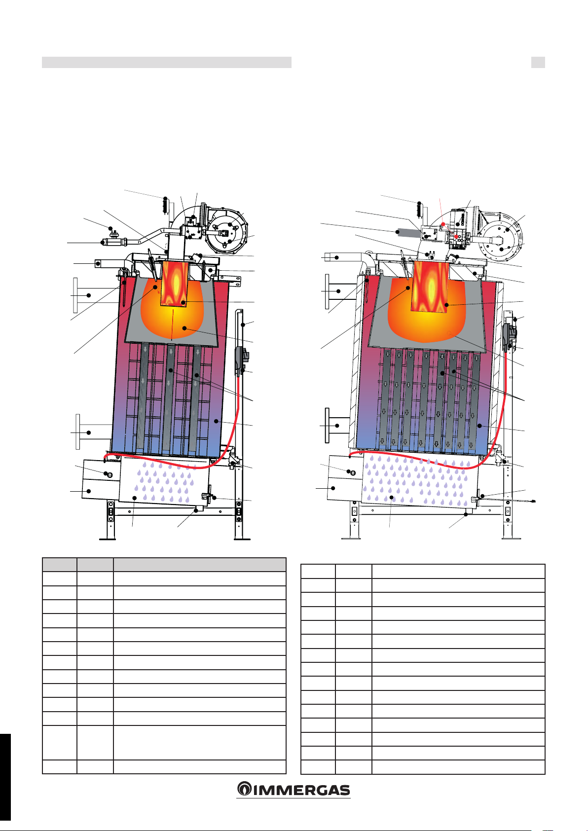
2.1 INTERNAL VIEW WITH INDICATIONS
OF MAIN COMPONENTS
ARES PRO 150 ARES PRO 230 - 300 - 400 - 500 - 600
Technical features and dimensions
G
64
M
27
R
32
S
*53
62
28
18
G
61
54
64
55
M
5
1
33
60
10-11
27
19
56
R
32
57
14
62
28
63
3
18
61
54
55
5
33
19
60
56
57
14
58
Key:
N° S.E. Description
3 VG Gas valve
5 Burner
10 TL Probe Limit ermostat
11 SR Central heating sensor
14 Boiler draining valve
18 VM Fan
19 PF Flue pressure switch
27 E. RIL. Detection electrode
28 E. ACC. Ignition electrode
32 Flue inspection point
33 Control panel
53
54 Glass inspection hole
STD.005480/000STD.005480/000
PGmin
PGmax
Gas pressure switch (min. *ARES PRO 150)
(min. ARES PRO 230 - 300)
(min. / max ARES PRO 348 ÷ 600)
59
55 Door insulation
56
57 Technical water tank
58 SL Level sensor
59 Condensate collection pan
60 Combustion chamber
61 Mixer Aria/gas
62 T.ACC Igniters
63 PFmin Min. ue pressure switch
64 Air vent tting
G Gas inlet
M Central heating system ow
R Central heating system return
S.cond Condensate drain DN 32
9
Stainless steel vertical smoke pipe with aluminium internal.
S.E. = WIRING DIAGRAM KEY
S.cond
H1
H
H3
H2
L1
L4
L2
A
G
M
S
Sm
H4
H5
H6
H7
R
L3
L5
Technical features and dimensions
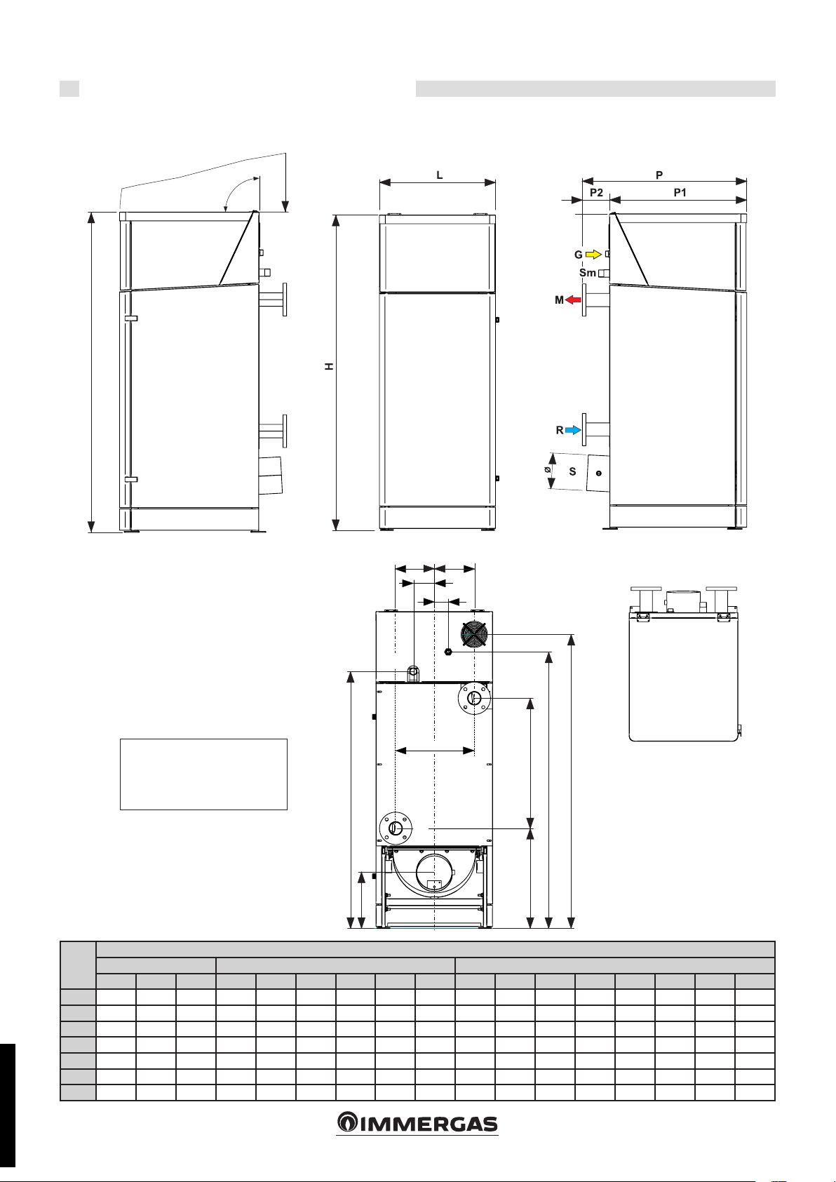
2.2 DIMENSIONS
SIDE VIEW SIDE VIEWFRONT VIEW
REAR VIEW TOP VIEW
NOTE:
Refer to the relative chapter
regarding the dimensions of the
ttings.
ARES
PRO
150 944 788 156 666 120 81 228.5 228.5 457 1809 65.6 1467 323.5 770 554.5 1579 1679
Depth Width Height
P P1 P2 L L1 L2 L3 L4 L5 H H1 H2 H3 H4 H5
230 1092 954 141 846 120 43 277 277 554 1917 65.6 1557 356 800 604.5 1697 1768
300 1181 1036 144 910 100 200 297 297 594 1946 65.6 1618 353 825 600.5 1741 1796
348 1276 1152 124 996 100 200 338 338 676 2130 65.6 1712 390 853 664 1794 1974
DIMENSIONS [mm]
H6 H7
400 1276 1152 124 996 100 200 338 338 676 2130 65.6 1712 390 853 664 1794 1974
500 1276 1152 124 996 100 200 338 338 676 2130 65.6 1712 390 853 664 1794 1974
600 1398
1256 142 1096 200 220 386 386 772 2206 65.6 1753 390 900 673 1863 2052
STD.005480/000STD.005480/000
10
P (P1+P2)
L
Lc
Lp
< 150
P
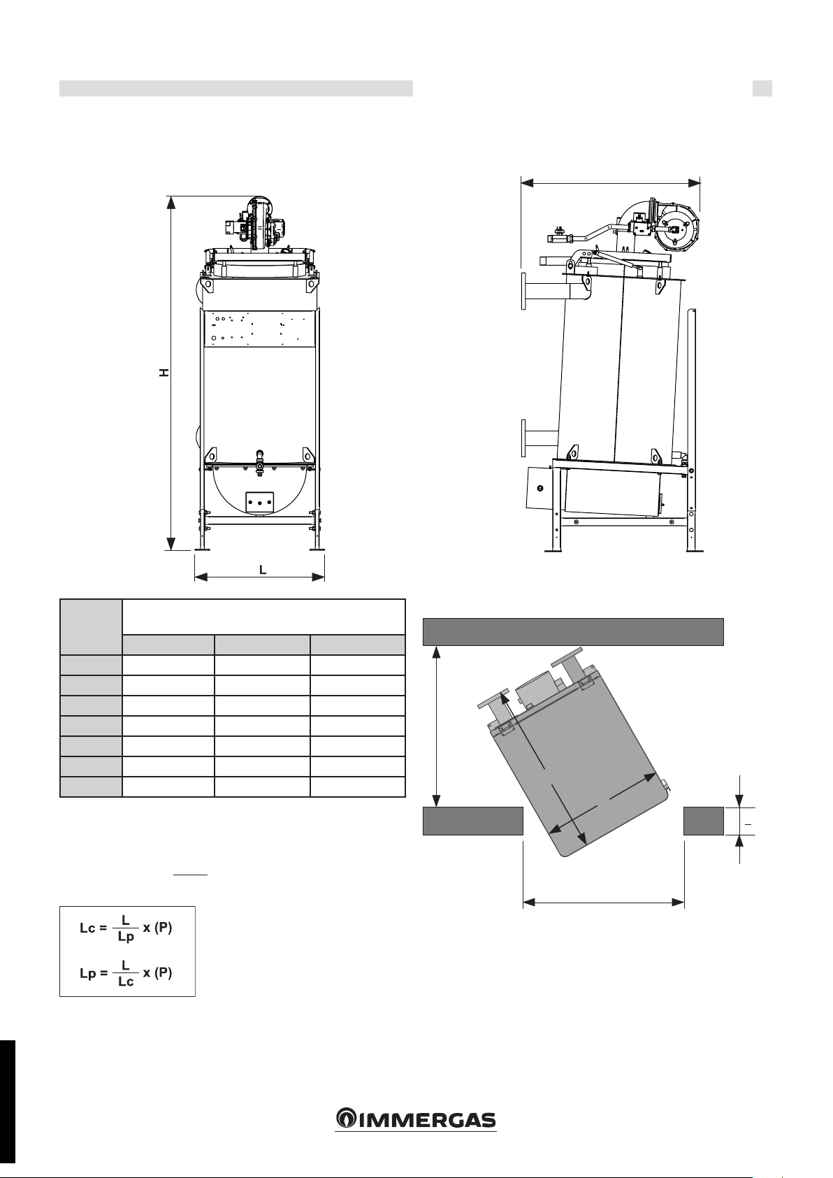
2.2.1 DIMENSIONS TO INSTALL THE BOILER IN HEATING
CONTROL UNIT
FRONT VIEW
Technical features and dimensions
SIDE VIEW
ARES
PRO
150 917 655 1785
230 1027 795 1895
300 1134 845 1910
348 1258 965 2075
400 1258 965 2075
500 1258 965 2075
600 1313 1065 2186
Example of corridor width (Lc) required to handle the boiler ARES
PRO 150:
BOILER DIMENSIONS WITHOUT
CASING [mm]
P L H
Lc =
666
x 944 = > 698 mm
900
L = Boiler width
P = Boiler depth
Lc = Corridor Width
Lp = Door Width
STD.005480/000STD.005480/000
11
Technical features and dimensions
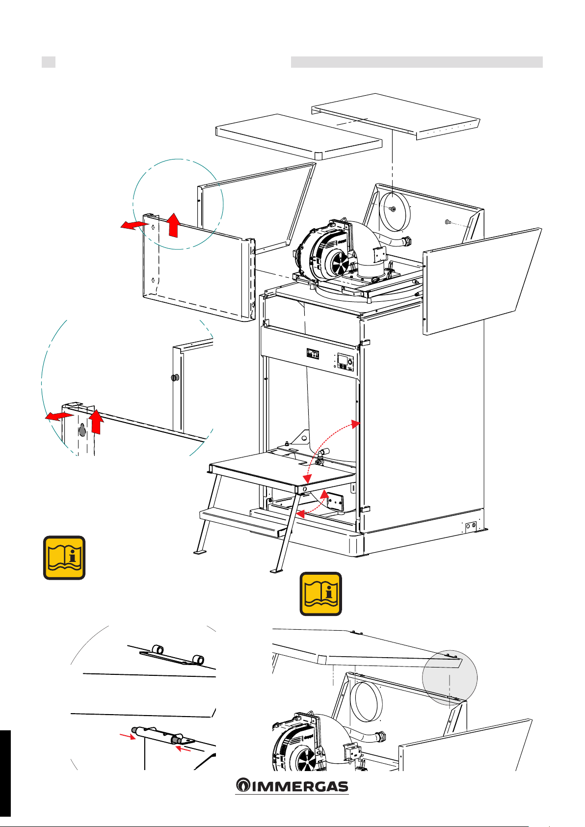
2.2.2 VIEW TO ACCESSIBILITY INSIDE
1
2
2
1
Series scale for models:
ARES PRO 348 - ARES
PRO 400 - ARES PRO
500 - ARES PRO 600
Optional for models:
ARES PRO 150 - ARES
PRO 230 - ARES PRO 300
ARES PRO 150 - ARES PRO 230 - ARES PRO 300
To remove the cover, release the 2 springs, refer to the
part shown below.
STD.005480/000STD.005480/000
12
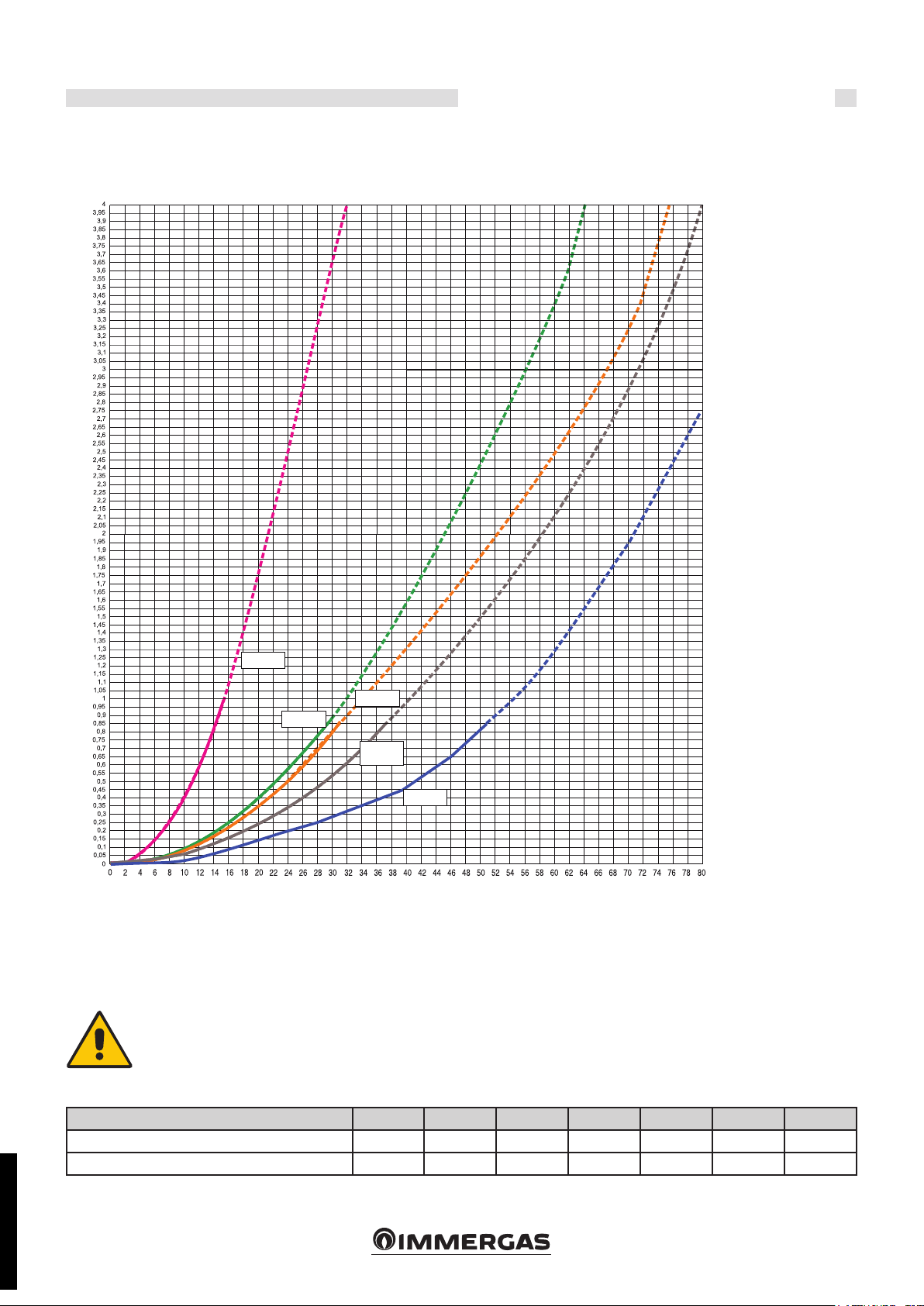
2.3 DIAGRAM OF WATER SIDE HEAD
LOSSES
Technical features and dimensions
Head losses (m/H20)
ARES PRO
150
ARES PRO
ARES PRO
230
2.3.1 DETERMINATION OF THE PRIMARY CIRCUIT PUMP
OR BOILER PUMP
e boiler pump must have head that can ensure circulator ow rates
according to the circuit’s ∆.
e pumps must be determined by the installer or
designer based on the data for the boiler and system.
300
ARES PRO
348 - 400 -
500
ARES PRO
600
Flow rate (m3/h)
e pump is not an integral part of the boiler.
It is advisable to choose a pump with a ow rate and head of approx-
imately 2/3 of its typical curve.
Maximum ow rate in l/h (∆t=15K)
Nominal requested ow rate in l/h (∆t = 20K)
STD.005480/000STD.005480/000
ARES PRO 150 230 300 348 400 500 600
7,818 11,999 15,740 19,575 21,386 25,338 30,978
5,863 9,000 11,805 14,681 16,039 19,004 23,234
13
Technical features and dimensions
2.4 FUNCTIONING DATA /
GENERAL FEATURES
ARES PRO 150 230 300 348 400 500 600
Boiler category II
Modulation ratio 1 : 4.0 1 : 4.3 1 : 4.3 1 : 3.9 1 : 4.2 1 : 3.9 1 : 4.4
Nominal heat input on L.V.C. Qn kW 140 214 280 348 380 450 550
Minimum heat input on L.C.V. Qmin kW 35 50 65 90 90 115 125
Nominal eective power (Tr 60 / Tf 80 °C) Pn kW 136.36 209.29 274.54 341.42 373.01 441.95 540.32
Minimum eective power (Tr 60 / Tf 80 °C) Pn min kW 32.52 48.25 63.57 87.67 87.80 111.09 118.53
Nominal eective power (Tr 30 / Tf 50 °C) Pcond kW 145.88 226.84 292.88 363.31 399.00 472.20 581.19
Minimum eective power (Tr 30 / Tf 50 °C) Pcond min
Eciency at nominal power (Tr 60 / Tf 80°C) % 97.4 97.8 98.05 98.11 98.16 98.21 98.24
Eciency at minimum power (Tr 60 / Tf 80°C) % 92.92 96.5 97.8 97.41 97.55 96.6 94.82
Eciency at nominal power (Tr 30 / Tm 50°C) % 104.2 106 104.6 104.4 105 104.9 105.67
Eciency at minimum power (Tr 30 / Tm 50°C) % 104.4 109.2 107.7 110.1 108 107.9 108.7
Eciency at 30% of the load ( Tr 30°C) % 107.7 107.2 108.9 108.4 108.8 108.9 106.5
Combustion eciency at nominal load % 97.8 97.9 98.2 98.2 98.2 98.2 98.3
Combustion eciency at a reduced load % 98.38 98.32 98.40 98.34
Losses from operating burner casing (Qmin) % 5.46 1.82 0.60 0.93 0.76 1.83 3.60
Losses from operating burner casing (Qn) % 0.4 0.1 0.1 0.1 0.1 0.03 0.04
Flue temperature at net of Tf-Ta (min)(*) °C 32.3 33.6 32 33.2 33.7 31.3 31.5
Flue temperature at net of Tf-Ta (max)(*) °C 44.2 42.7 36.7 35.6 35.4 35.5 34.3
Maximum permitted temperature °C 100
Maximum operating temperature: °C 90
Mass ue ow rate (min) kg/h 57 82 106 147 147 188 204
Mass ue ow rate (max) kg/h 229 350 458 569 621 735 899
Air excess % 25.53
Chimney losses with burner in operation (min) % 1.62 1.68 1.60 1.66 1.69 1.57 1.58
Flue losses with burner in operation (max) % 2.21 2.14 1.84 1.78 1.77 1.78 1.72
Minimum pressure of heating circuit bar 0.5
Maximum pressure of heating circuit bar 6
Water content l 153 210 270 340 340 340 425
Methane gas consumption G20 (supp.press. 20 mbar) at Qn
Methane gas consumption G20 (supp.press. 20 mbar) at Qn
Propane gas consumption (supp.press. 37/50 mbar) at Qn
Propane gas consumption (supp.press. 37/50 mbar)
at Qn
Maximum pressure available at ue base Pa 100
Max condensate production kg/h 11.5 13.7 15.8 29.1 28.5 28.8 31.0
Emissions
CO at maximum heat input with 0% O2
NOx at maximum heat input with 0% O2
NOx class 6
Electrical data
Frequency/Power supply voltage: V/Hz 230/50
Supply fuse A (R) 6
Degree of protection IP
kW 36.54 54.60 70.01 99.09 97.20 124.09 135.88
m3/h 14.80 22.63 29.61 36.80 40.18 47.58 58.15
m3/h 3.70 5.29 6.87 9.52 9.52 12.16 13.22
kg/h 10.87 16.61 21.73 27.01 29.50 34.93 42.69
kg/h 2.72
mg/kWh
mg/kWh
13.73 18.05 28.08 25.27 18.25 22.46 22.1
54 43 53 49 50 48 50
3.88 5.05 9.70 6.99 8.93 8.70
2H3P
98.31 98.43 98.42
X4D
STD.005480/000STD.005480/000
Room Temperature = 20°C
(*) Temperatures read with the device operating with ow 80°C / ret. 60°C
CO
(min/max) See “NOZZLES - PRESSURES” table
2
Seasonal Energy Eciency
Losses at shutdown at ∆T 30°C - Pstb - see Table ErP
Electrical consumption in standby - Psb - see Table ErP
according to 2009/125 EEC (<=400Kw)
14
ηs - see Table ErP

Technical features and dimensions
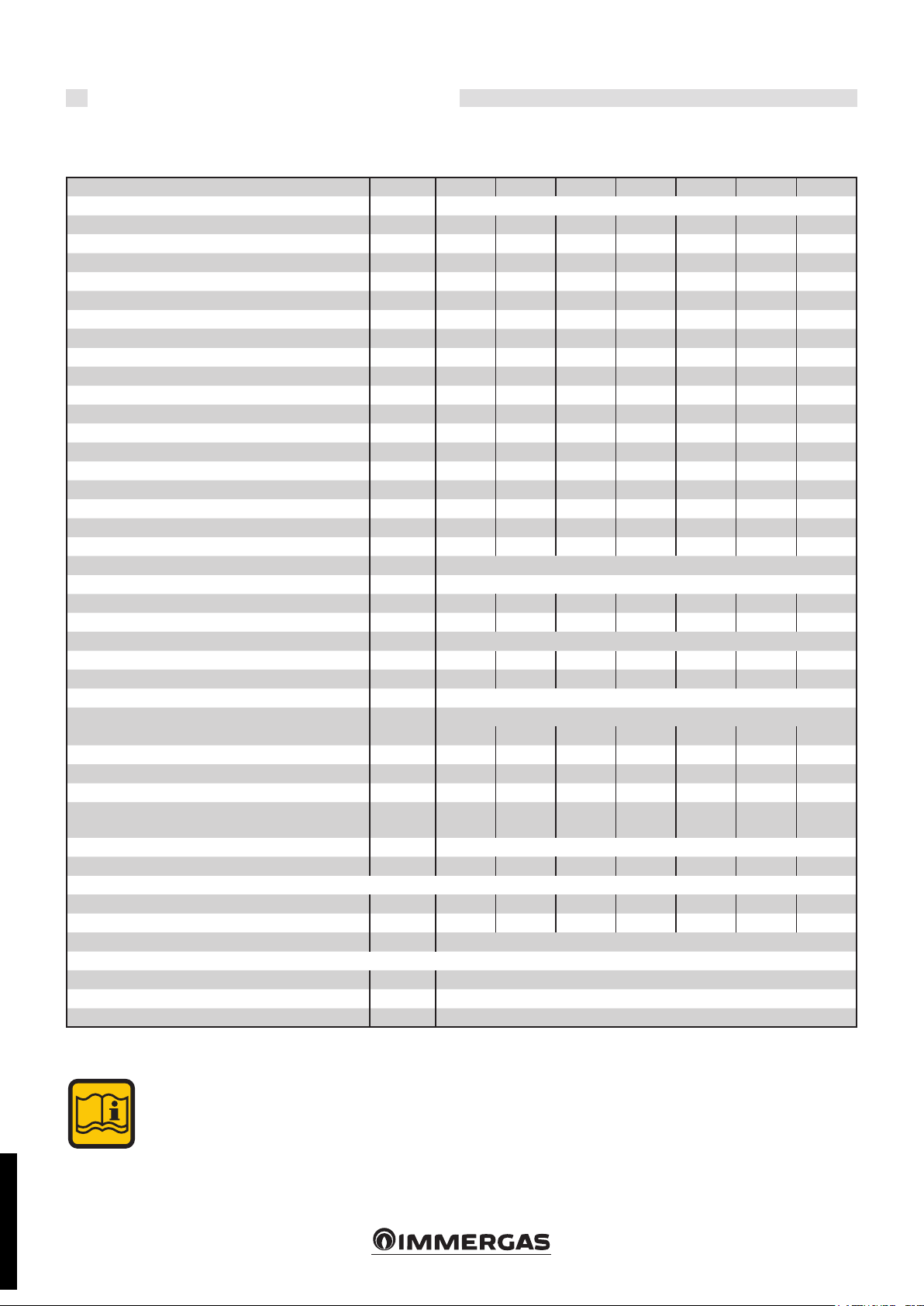
2.5 TECHNICAL PARAMETERS FOR COMBINATION BOILERS
IN COMPLIANCE WITH REGULATION 813/2013.
Eciencies in the following tables refer to the gross caloric value.
Model/s: ARES PRO 150
Condensing Boilers: YES
Low temperature boiler: NO
Boiler type B1: NO
Co-generation appliance for central heating: NO Fitted with supplementary heating system: NO
Mixed heating appliance: NO
Element Symbol Valu e Unit Element Symbol Value Unit
Nominal heat output P
n
136 kW
For central heating only and combination boilers: useful heat output For central heating only and combination boilers: useful eciency
At nominal heat output in high tempera-
ture mode (*)
At 30% of nominal heat output in a low
temperature mode (**)
P
4
P
1
136.3 kW
45.2 kW
Auxiliary electricity consumption Other items
At full load el
At partial load el
In standby mode P
0.190 kW Heat loss in standby P
max
0.042 kW Annual electrical consumption Q
min
0.005 kW Emissions of nitrogen oxides ref. PCI (PCS) NOX59 (53)
SB
For mixed central heating appliances
Seasonal energy eciency of central
heating
At nominal heat output in high temperature mode (*)
At 30% of nominal heat output in a low
temperature mode (**)
η
η
η
stby
HE
s
4
1
93 %
87.8 %
97.0 %
0.32 kW
424 GJ
mg /
kWh
Stated load prole Domestic hot water production eciency η
Daily electrical power consumption Q
elec
kWh Daily gas consumption Q
WH
fuel
%
kWh
Contact information IMMERGAS S.p.A. VIA CISA LIGURE, 95 - 42041 BRESCELLO (RE) ITALY
(*) High temperature mode means 60°C on return and 80°C on ow.
(**) Low temperature mode for condensation Boilers means 30°C , for low temperature boilers 37°C and for other appliances 50°C of return temperature.
STD.005480/000STD.005480/000
15
 Loading...