

Immergas ARES 440 TEC ERP, ARES 660 TEC ERP, ARES 770 TEC ERP, ARES 900 TEC ERP, ARES 550 TEC ERP Instructions And Warnings
Page 1
*1.039293ENG*
Instructions and warnings
Installer
Maintenance technician
IE
ARES 440 TEC ERP
ARES 550 TEC ERP
ARES 660 TEC ERP
ARES 770 TEC ERP
ARES 900 TEC ERP
Modular condensing boiler
Page 2

Page 3

Warning this manual contains the exclusive instructions for use for professionally qualied
installers and/or maintenance technicians, in compliance with laws in force.
e individual in charge of the system is NOT authorised to work on the boiler.
e manufacturer will not be held liable in the case of damage to people, animals or property
due to the failure to observe the instructions contained in the manuals supplied with the boiler.
INDEX
1 General information ...................................................................4
1.1 Symbols used in the manual ........................................................4
1.2 Compliant use of the appliance ...................................................4
1.3 Information to be provided to the user .....................................4
1.4 Safety warnings .............................................................................5
1.5 Regulations for installation..........................................................6
1.6 Installation .....................................................................................6
1.7 Water treatment ............................................................................7
1.8 general warnings ...........................................................................8
2 Technical characteristics and dimensions .................................9
2.1 Technical characteristics .............................................................. 9
2.2 View of main parts ......................................................................10
2.3 Dimensions ..................................................................................11
2.4 Operating data / general characteristics ..................................12
3 Instructions for installation .....................................................13
3.1 General recommendations ........................................................13
3.2 Packaging .....................................................................................14
3.3 Operation to unload and remove the packaging ...................15
3.4 Positioning the heating control unit.........................................16
3.5 Connecting the boiler ................................................................17
3.6 Gas connection............................................................................18
3.7 System ow and return pipe connection .................................19
3.8 Additional safety, protection and control devices ..................20
3.9 Hydraulic separator ....................................................................21
3.10 Hydraulic system lter ...............................................................21
3.11 Determining the primary circuit pump or boiler pump .......22
3.12 Ball valves .....................................................................................22
3.13 complete optional kits ................................................................23
3.14 condensate drain .........................................................................24
3.15 Connecting the ue ....................................................................25
3.16 Flue exhaust manifold connection ...........................................25
3.17 Electrical connections ................................................................27
General recommendations ........................................................27
230V electrical supply connection ...........................................28
3.18 Connection diagram ..................................................................29
Power supply, gas electrovalve, INAIL, ON/OFF
pump, external probe, ow switch. ...........................................29
Power supply, gas electrovalve, INAIL, modulating pump,
external probe, ow switch. .......................................................29
INAIL safety connection
(supplied with modulating pump). .......................................... 30
ON/OFF thermostat connection. .............................................30
Modulating room thermostats connection. ............................31
Modulating zone manager connection. ...................................31
3.19 Practical connection diagram ...................................................32
3.20 Connections and management diagram ..................................34
3.21 Examples of installation (functional diagram and
description of connections) .......................................................36
3.22 System lling and emptying ......................................................41
3.23 Boiler frost protection ................................................................41
3.24 Check the adjustment of the pressure to the burner .............. 42
Nozzles - pressures. ....................................................................44
3.25 Emergency and safety operations ............................................46
3.26 First ignition ................................................................................47
4 Inspections and maintenance ..................................................48
CE DECLARATION OF CONFORMITY
(according to ISO/IEC 17050-1)
e company IMMERGAS S.p.A., with registered oce in via Cisa Ligure 95 42041 Brescello (RE) whose design, manufacturing, and aer sale
assistance processes comply with the requirements of standard UNI EN ISO 9001:2008,
DECLARES that:
e ARES 440 TEC ERP, ARES 550 TEC ERP, ARES 660 TEC ERP, ARES 770 TEC ERP, ARES 900 TEC ERP model boilers comply with the
following European Directives and Delegated European Regulations:
“Eco-design” Directive 2009/125/EC, “Energy labelling” Directive 2010/30/EC, “Gas Appliance” Directive 2009/142/EC, “Electromagnetic Compatibility” Directive 2004/108/EC, “Performance” Directive 92/42/EC and “Low Voltage” Directive 2006/95/EC.
Mauro Guareschi
Research & Development Director
Signature:
Immergas S.p.A. declines all liability due to printing or transcription errors, reserving the right to make any modications to its technical and
commercial documents without prior notice.
Page 4
General information
GENERAL
1
INFORMATION
1.1 SYMBOLS USED IN THE MANUAL
When reading this manual, pay special attention to the parts marked with these symbols:
DANGER!
Serious danger to
safety and life
for the product and environment
ATTENTION!
Possibly dangerous situation
1.2 COMPLIANT USE OF THE APPLIANCE
e ARES Tec appliance was built based on the current technical level and recognised technical safety rules.
Nevertheless, following improper use the safety and life of the user or other people may be exposed to danger, i.e. damage
to the appliance or other objects.
e appliance is designed for operation in hot water circulating heating systems.
Any other use is considered improper.
Immergas will not be held liable for any damage resulting from improper use.
Any use in accordance with the envisioned purposes includes the strict observance of the instructions in this manual.
1.3 INFORMATION TO BE PROVIDED TO THE USER
e user must be instructed in the use and operation of his/her heating system, in particular:
- Deliver these instructions to the user, as well as the other documents relative to the appliance contained in the packaging in
an envelope. e user must keep this documentation safe so that it is available for future consultation.
- Inform the user of the importance of aeration vents and the ue exhaust system, highlighting how essential they are and how
it is strictly forbidden to change them.
- Inform the user on how to control the water pressure in the system as well as the operations required to restore it.
- Inform the user on how to correctly regulate the temperature, control units/thermostats and radiators in order to save energy.
- Remember it is compulsory to carry out regular maintenance on the system once a year and a combustion analysis every two
years (as per national legislation).
- If the appliance is sold or transferred to another owner or if the owner moves, leaving the appliance behind, always ensure the
handbook accompanies the appliance so that it may be consulted by the new owner and/or installer.
NOTE!
Tips for the user
e manufacturer will not be held liable in the case of damage to people, animals or property due to the failure to observe the instructions
contained in this manual.
4
Page 5
1.4 SAFETY WARNINGS
ATTENTION!
e appliance must not be used by people with reduced physical, mental and sensorial capabilities, without experience and
knowledge. ese people must be duly instructed and supervised during manoeuvring operations.
ATTENTION!
Installation, adjustment and maintenance of the appliance must be carried out by professionally qualied sta, in compliance
with regulations and provisions in force, as incorrect installation can cause damage to people, animals and property, for
which the manufacturer will not be held liable.
DANGER!
Maintenance or repair work on the boiler must be carried out by professionally qualied sta, authorised by Immergas;
it is advisable to sign a maintenance contract.
Poor or irregular maintenance can compromise the operational safety of the appliance and cause damage to people, animals
and property for which the manufacturer will not be held liable.
Changes to parts connected to the appliance
Do not make changes to the following elements:
- to the boiler
- to the gas, air, water and power supply lines
- to the ue pipe, safety valve and exhaust pipe
- to the constructive elements that aect the operational safety of the appliance.
General information
Attention!
To tighten or loosen the screw-attached ttings, use suitable wrenches only.
Improper use and/or unsuitable tools can cause damage (for ex. water and gas leaks).
ATTENTION!
Instructions for appliances running on propane gas
Make sure that the gas tank has been deaerated prior to installing the appliance.
For a thorough deaeration of the tank contact the liquid gas supplier and in any case authorised sta, in accordance with the law.
Ignition problems can arise if the tank is not thoroughly deaerated.
In this case contact the liquid gas tank supplier.
Smell of gas
In case of the smell of gas observe the following safety instructions:
- do not use electric switches
- do not smoke
- do not use the telephone
- shut o the gas cut-o valve
- aerate the room where the gas leak occurred
- notify the gas supply company or a company specialised in the installation and maintenance of heating systems.
Explosive and easily ammable substances
Do not use or deposit explosive or easily ammable materials (for ex. petrol, paints, paper) in the room where the appliance is
installed.
ATTENTION!
e heat unit must be installed so as to avoid, under the envisioned operating conditions, the liquid contained in it from freezing
and avoid exposing the command and control parts to temperatures below -15°C and over +40°C.
e heat unit must be protected from climatic/environmental variations by:
- insulating the hydraulic and condensation exhaust pipes
- adopting specic anti-freeze products in the hydraulic system.
5
Page 6
General information
1.5 REGULATIONS FOR INSTALLATION
ARES Tec is a gas category II
e appliance must be installed in accordance with the instructions
contained in this manual.
Installation must be carried out by an authorised professional
technician, who is in charge of enforcing observance of all local
and/or national laws published in the Ocial Gazette, as well as all
applicable technical regulations.
It is necessary to observe the standards, regulations and requirements
for installation provided below, constituting a rough and non-exhaustive
list, in order to follow the evolution of the "state of the art". We
would like to underline that updating the list of standards is the
responsibility of the technicians authorised to carry out installation.
heat unit.
2H3P
Also observe the standards regarding the heating control unit,
construction regulations and requirements on combustion heating in
the country of installation.
The appliance must be installed, commissioned and subject to
maintenance in accordance with the current "state of the art". is also
applies to the hydraulic system, the ue exhaust system, the installation
room and the electrical system.
Failure to observe the above regulations will void
the warranty.
1.6 INSTALLATION
When the appliance is installed on existing systems, make sure that:
- e ue is suitable for condensation appliances, for the temperatures
of the combustion products, calculated and built in accordance with
regulations in force. at is it a straight as possible, water-tight and
insulated and does not have any obstructions or constrictions.
- e ue is equipped with an attachment to evacuate the condensation.
- e heating control unit is equipped with a pipe for the evacuation
of the condensation produced by the boiler.
- e electrical system is built in accordance with specic regulations
and qualied technical personnel.
- e ow rate, head and direction of ow of the circulation pumps is
appropriate.
- e fuel feed line and any existing tanks are set up in accordance with
regulations in force.
- e expansion vessels ensure complete absorption of the dilation of
the uid contained in the system.
- Slurry and build-up have been cleaned out of the system.
If ARES Tec is being installed on existing Systems:
If it is possible to schedule the replacement, it is necessary to wash
the system preventively, with alkaline dispersants. Washing must be
carried out four weeks prior to replacement, with a system operating
between 35°C - 40°C.
Attention!
If the new boiler has been replaced in an old system
without having preventively washed it as described
above, do not wash the system, as any residues of
the product in the circuit may ll the generator with
residues aer replacement.
It is advisable to contact a company specialised in
water treatment.
Otherwise, if ARES Tec is being installed on a new system it is advisable
to wash it thoroughly in any case, using products that are suitable for
the entire system, and install a Y-strainer with two cut-o valves on the
return pipe to the boiler, so that it can be cleaned as needed.
is lter will protect the boiler from sediments coming from the
heating system.
In both cases it is necessary to keep the head losses localised in the
primary circuit, for the correct sizing of the pump.
6
Page 7
General information
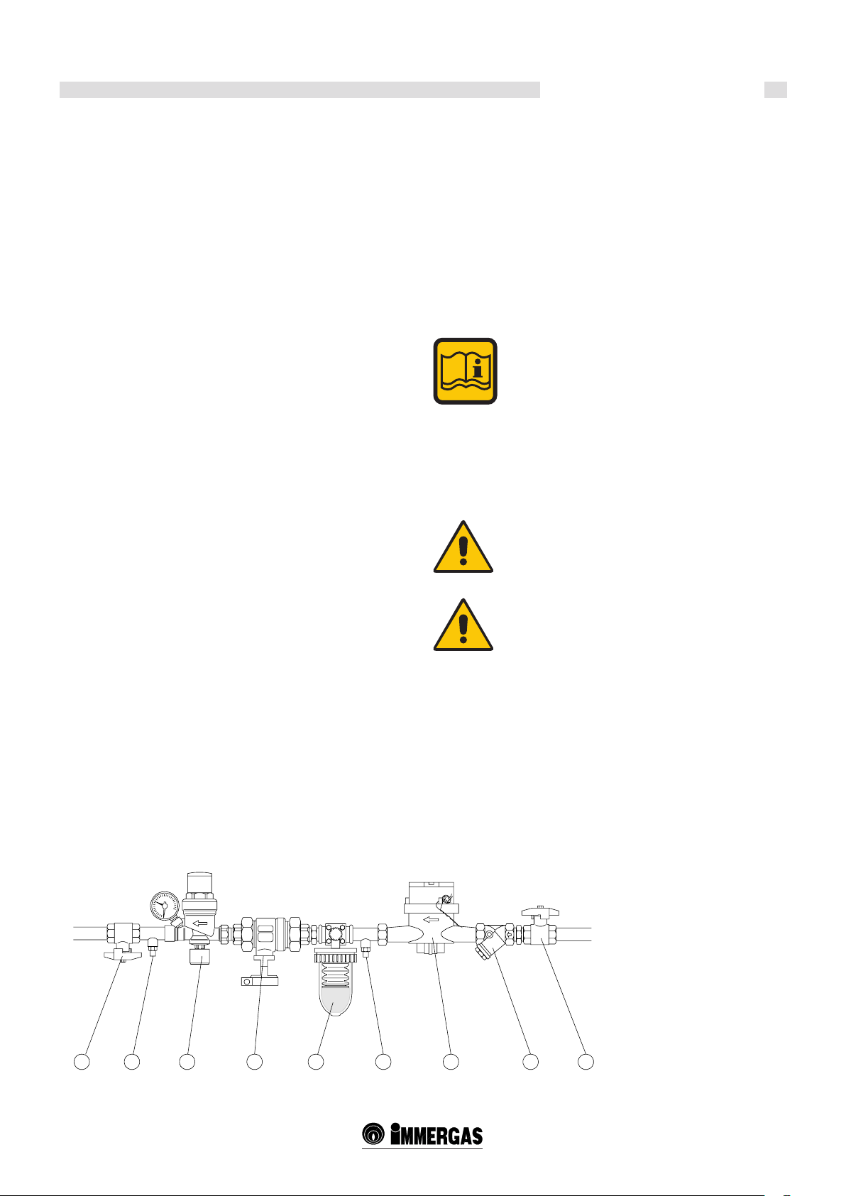
1.7 WATER TREATMENT
Treating the supply water allows you to prevent problems and
maintain the functionality and eciency of the generator over time.
e purpose of this treatment is to eliminate or signicantly reduce
problems that can be outlined as:
build-up
corrosion
sediments
biological growth (mould, fungus, algae, bacteria, etc.)
e chemical analysis of the water provides a lot of information on the
state and "health" of the system.
e pH level is a numerical indication of the acidity or alkalinity of
a solution.
e pH scale goes from 0 to 14, where 7 corresponds to neutral.
Values below 7 indicate acidity, values above 7 indicate alkalinity.
e ideal pH value in heating systems with aluminium boilers is
between 6.5 and 8, with a hardness of 15°F.
Water in a system with a pH value outside of this range considerably
accelerates the destruction of the protective oxide layer which forms
naturally inside the aluminium bodies, and would not occur naturally:
if the pH level is lower than 6 it contains acid, if it is above 8 the water is
alkaline, either due to an alkaline treatment (for example phosphates or
glycols operating as antifreeze) or in some cases the natural generation
of alkalis in the system.
Vice versa, if the pH value is between 6.5 and 8, the aluminium surfaces
in the body are passivated and protected from further corrosive attacks.
To minimise corrosion, it is essential to use a corrosion inhibitor.
In order for it to work eciently, however, the metal surfaces must
be clean.
The best inhibitors on the market also contain an aluminium
protection system that stabilises the pH levels of the ller water,
preventing sudden changes (buer eect).
It is advisable to systematically check (at least twice a year) the
pH value of the water in the system. In order to do so a chemical
laboratory analysis is not required, but a simple check using a
analysis "kit" contained in a carry cases, easily available on the
market.
It will therefore be necessary to set up the devices shown in the gure
in the heating system.
THE COUPLING MUST BE SET UP ON THE
RETURN PIPE TO THE PRIMARY CIRCUIT
DOWNSTREAM OF THE PUMP.
All of the precautions required to avoid the formation and localisation of
oxygen in the water of the system. For this reason the plastic pipes used
in the under-oor heating systems must not be permeable to oxygen.
Make sure that any anti-freeze products are compatible with aliminium
and any other parts and materials in the system.
ATTENTION!
Any damage caused to the boiler, due to the formation
of build-up or corrosive water, will not be covered by
the warranty.
Example of water treatment unit
ATTENTION!
These appliances are designed and developed to
transfer heat to a heat carrying uid possessing the
characteristics described here, they are not suitable to
directly heat water intended for human consumption.
Key:
1 - Ball valve
2 - Sample trap
3 - Filling unit
4 - Cut-o device
5 - Water treatment unit
6 - Litre meter (recommended)
7 - "Y" strainer
1 2 3 4 5 2 7 16
7
Page 8

General information
1.8 GENERAL WARNINGS
e instruction handbook is an integral and essential part of the product
and must be kept safe by the individual in charge of the system.
Read the warnings contained in the handbook carefully, as they provide
important instructions regarding installation, user and maintenance
safety.
Keep the handbook safe for future consultation.
e appliance must be installed and maintained in accordance
with regulations in force, pursuant to the instructions of the
manufacturer, the state of the art and by authorised and qualied
personnel, in accordance with the law.
Professionally qualied personnel means sta with specic technical
skills in the sector of heating system parts for civil use, hot water
production for domestic use and maintenance. is personnel must
have the authorisations required by legislation in force.
Incorrect installation or poor maintenance can cause injury to persons
and animals and damage to objects, for which the manufacturer is
not liable.
Before carrying out any cleaning or maintenance operations, cut the
appliance o from the power mains by acting on the switch on the
system and/or using the cut-o devices.
Any repairs to the products must be carried out by authorised Immergas
personnel only, using original spare parts only. Failure to observe
the above can jeopardise the safety of the appliance and will void the
warranty.
e guarantee the eciency of the appliance and its correct operation it
is essential for authorised personnel to carry out annual maintenance.
If the appliance is put out of use for downtime, any part that is
susceptible to posing a potential source of danger must be made safe.
Before re-commissioning an appliance that has been put out of use,
proceed to washing the domestic hot water production system, making
water ow through it for the amount of time required to change the
water completely.
If the appliance is sold or transferred to another owner or if the owner
moves, leaving the appliance behind, always ensure the handbook
accompanies the appliance so that it may be consulted by the new
owner and/or installer.
All appliances with optionals or kits (including electric) must only use
original spare parts.
e appliance must only be employed for its expressly foreseen use.
Any other use must be considered improper and therefore dangerous.
Do not obstruct the intake/exhaust pipe terminals.
In case of breakdown and/or poor operation of the appliance, switch it
o, and do not attempt in any way to repair it or intervene directly. Only
contact personnel that has been authorised in accordance with the law.
8
Page 9

Technical characteristics and dimensions
TECHNICAL
2
CHARACTERISTICS AND
DIMENSIONS
2.1 TECHNICAL CHARACTERISTICS
- Heat generator, to heat Low Nox condensation gas
- Comprised of a heat module designed to operate on its own or in a
set
- Can be set up directly outside (IP X5D)
- Low water content
- High response speed to load changes
- Single ue exhaust that can be positioned on 3 sides
- Unied ow and return hydraulic manifolds
- Comprised of 4 or more heating elements (between 4 and 8),
aluminium/silicon/magnesium casting
- Including total irradiation premixing modulating burners
- None of the heating elements have hydraulic cut-o devices
- Single gas supply pipe
- Modulated power between 22 ÷ 108 kW/element.
TEMPERATURE CONTROL DEVICES:
- ROOM NTC sensor (every heating element)
- Room Limit ermostat (every heating element)
- Flow NTC sensor (General)
- Return NTC sensor (General)
- Approved safety thermostat (To be ordered and installed on INAIL
section in parag. 3.8)
- GCI global ow probe.
OTHER SAFETY DEVICES according to the R COLLECTION
see parag. 3.8
POP-UP control panel composed of:
- ON-OFF switch see parag. 3.25
- TGC boiler thermoregulation/manager
- GCI (internal cascade management board)
- Protection fuses
- Any limit thermostats
- Fan air pressure switch
- Condensation water level sensor
- Gas pressure switch
- Exhaust pressure switch (anti-obstruction).
- e entire heating unit is equipped with global temperature control
NTC sensors on the ow and return manifolds.
- Integral insulation with non-allergenic synthetic wool.
- Total premix burner, modulating, with "metal foam" radiation
combustion chamber. Premixing in the fan. Automatic separating
backow diaphragm from the combustion chamber.
- Sound emissions at maximum power below 49 dBA.
- Operation during heating: determining the instantaneous power
through a control microprocessor, with preset comparison parameters
between requested temperature (or calculated by the outdoor
thermoregulation) and global ow temperature.
- Logic of operation:
- Possibility of controlling the power of the single heating elements
for calibration and/or assistance with reserved access code.
- D.H.W. production through priority NTC probe, to control the
storage tank load through a pump or three-way deviator valve
through the supplied TGC thermoregulator.
- Possibility of controlling the power of the single heating elements.
- Heat request control: temperature setpoint and modulation level.
- Monitoring the state of operation and temperatures.
- Alarm notication.
- Parameter setting.
- Control relay to switch on a pump at a xed speed.
- Analogue 0÷10V output to control a modulating pump.
- Emergency operation: this allows you to avoid the system from
stopping due to an interruption in communication with the adjusting
system or possible remote management of the control unit:
- e possibility of selecting the emergency temperature through
supplied "Constant Setpoint" heating elements: 70°C, maximum
power 50%.
- Alarm management.
- Alarm reset input.
- Alarm notication Relay.
- Condensation collection tray with stainless steel exhaust trap.
- Easily removable integral panelling comprised of oven-painted steel
panels suitable for outdoor installation.
- Condensation collection tray with stainless steel exhaust trap and ue
chamber.
- Incorporated deaerator.
e request for heat can be generated by the TGC thermoregulation/
manager or alternatively by the GCI (internal cascade management
board).
The management logic envisions simultaneous operation of the
maximum number of heat elements, so as to always obtain the
maximum eciency. Since it guarantees the maximum exchange area
based on the delivered power. e elements are made to operate so as
to equally divide the operating time.
e hot water that is produced is pushed by the pump located on the
return of the primary ring to the ow of the hydraulic separator. From
here a second pump (system - see suggested diagrams) will distribute to
the various utilities. From the system, return the cooled water is taken
in by the pump on the return, through the hydraulic separator, to start
the cycle towards the generator again.
9
Page 10
Technical characteristics and dimensions
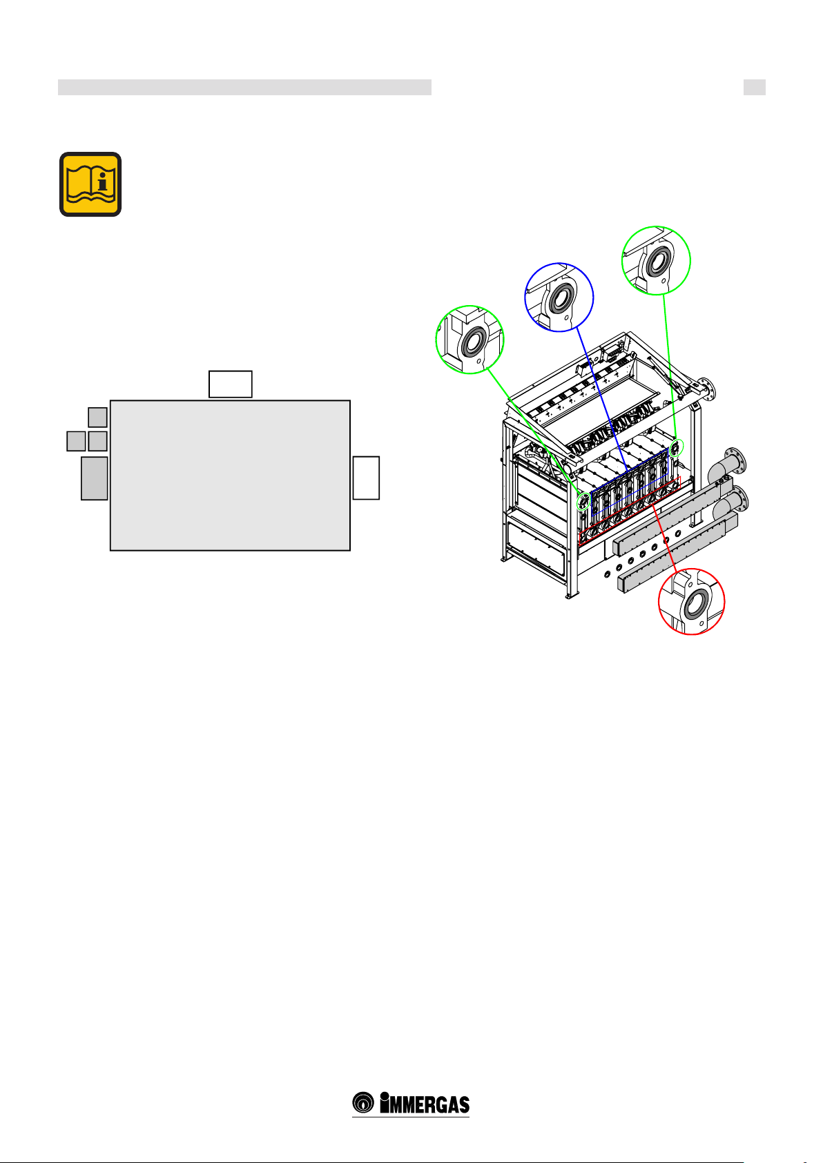
2.2 VIEW OF MAIN PARTS
GAS PIPE
TUBO GAS
Valvola gas
GAS VALVE
FAN
Ventilatore
AUTOMATIC
SFIATO ARIA
AIR BLEED
AUTOMATICO
VALVE
Camer a
COMBUSTION
di
CHAMBER
comb ustione
MANDATA
HEAT. FLOW
RISCALD AM.
Pannello
PANEL
BURNER
COPERCHIO
BR UCIATORE
COVER
Bruciatore
BURNER
Elettrodo
IGNITION
ELECTRODE
di accensione
Te rmostato
SAFETY
THERMOSTAT
di sicurezza
RITORNO
HEAT.
RISCALD AM.
RETURN
CONDENSATION
BACINELLA
COLLECTION
RACCOGLI
PAN
CONSENSA -
RACCORDO
FLUE FITTING
CAMINO
TELAIO
FRAME
TRAP
Sifone
Profondità min. 100 mm
Min. depth 100 mm
Elemento
STUDDED
ELEMENT
piolinato
CONDENSATE
Collettore
COLLECTION
raccogli condensa
MANIFOLD
LEVEL
Sensore di
SENSOR
livello
ue outlet LEFT, RIGHT, REAR side
ow LEFT side
return LEFT side
Gas inletLEFT side
GCI: under the front casing
10
Page 11
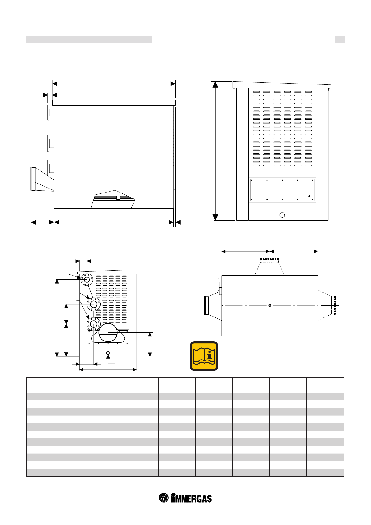
2.3 DIMENSIONS
62,5
Technical characteristics and dimensions
FRONT VIEW RIGHT SIDE VIEW
(Supply condition for le side attachments)
L
1448
S
287
L1
24
TOP VIEW
LEFT SIDE VIEW
122
G
M
R
327
1267
534
235
S
946
39 5
Flue outlets:
Le side (supply condition)
Right side
Rear side
=
=
ARES Tec 440 550 660 770 900
Dimensions Unit
Heating elements n° 4 5 6 7 8
Height mm 1448 1448 1448 1448 1448
Width "L" mm 1087 1355 1355 1623 1623
Width "L1" mm 1039 1307 1307 1575 1575
Depth mm 946 946 946 946 946
Attachment sizes
G Gas tting mm (inch) 80 (3) 80 (3) 80 (3) 80 (3) 80 (3)
F System ow mm (inch) 100 (4) 100 (4) 100 (4) 100 (4) 100 (4)
R System return mm (inch) 100 (4) 100 (4) 100 (4) 100 (4) 100 (4)
Flue tting mm 250 250 300 300 300
Condensate drain mm 40 40 40 40 40
11
Page 12
Technical characteristics and dimensions
2.4 OPERATING DATA / GENERAL CHAR
ACTERISTICS
ARES Tec 440 550 660 770 900
Boiler category II
2H3P
Nominal heat input on L.V.C. Qn kW 432 540 648 756 864
Minimum heat input on L.C.V. Qmin kW 22 22 22 22 22
Nominal eective power (Tr 60 / Tf 80°C) Pn kW 424,27 530,33 636,40 742,47 848,53
Minimum eective power (Tr 60 / Tf 80°C) Pn min kW 20,57 20,57 20,57 20,57 20,57
Nominal eective power (Tr 30 / Tf 50°C) Pcond kW 445,39 557,82 670,03 783,22 900,29
Minimum eective power (Tr 30 / Tf 50°C) Pcond min kW 23,94 23,94 23,94 23,94 23,94
Eciency at nominal power (Tr 60 / Tf 80°C) % 98,21 98,21 98,21 98,21 98,21
Eciency at minimum power (Tr 60 / Tf 80°C) % 93,5 93,5 93,5 93,5 93,5
Eciency at nominal power (Tr 30 / Tf 50°C) % 103,1 103,3 103,4 103,6 104,2
Eciency at minimum power (Tr 30 / Tf 50°C) % 108,8 108,8 108,8 108,8 108,8
Eciency class according to directive 92/42 EEC -- 4 4 4 4 4
Combustion eciency at nominal load % 98,28 98,28 998,28 98,28 98,30
Combustion eciency at minimum load % 98,45 98,45 98,45 98,45 98,45
Losses from operating burner casing % 0,1 0,1 0,1 0,1 0,1
Losses from burner casing when switched o -- 0,1 0,1 0,1 0,1 0,1
Chimney losses with burner on % 1,55 1,55 1,55 1,55 1,55
Flue temperature at net of Tf-Ta (max) °C 45,4 45,5 45,5 45,5 45,3
Maximum ue ow rate (max) kg/h 706,0 882,5 1059,1 1235,6 1412,1
Air excess % 25,5 25,5 25,5 25,5 25,5
(**) CO2 (min/max) % - - - - NOX (weighted value according to EN 15420)
mg/kWh
47 47 47 47 47
NOX class -- 5 5 5 5 5
Water ow rate at nominal power (∆T 20°C) l/h 18243,5 22804,4 27365,2 31926,1 36487,0
Minimum pressure of heating circuit bar 0,5 0,5 0,5 0,5 0,5
Maximum pressure of heating circuit bar 6,0 6,0 6,0 6,0 6,0
Water content l 73 88 103 118 133
Methane gas consumption G20 (supp.press. 20 mbar) at Qn m3/h 45,68 57,10 68,52 79,94 91,36
Methane gas consumption G20 (supp.press. 20 mbar) at Qmin m3/h 2,33 2,33 2,33 2,33 2,33
Gas consumption G25 (supp.press. 20/25 mbar) at Qn m3/h 53,13 66,41 79,69 92,97 106,25
Gas consumption G25 (supp.press. 20/25 mbar) at Qmin m3/h 2,71 2,71 2,71 2,71 2,71
Propane gas consumption (supp.press. 37/50 mbar) at Qn kg/h 33,53 41,92 50,30 58,68 67,07
Propane gas consumption (supp.press. 37/50 mbar) at Qmin kg/h 1,71 1,71 1,71 1,71 1,71
Maximum pressure available at ue base Pa 100 100 100 100 100
Max condensate production kg/h 69,5 86,9 104,3 121,7 139,1
Emissions
CO with 0% of O2 in the exhaust ppm <95 <95 <95 <95 <95
NOx with 0% of O2 in the exhaust ppm <30 <30 <30 <30 <30
Sound dBA <49 <49 <49 <49 <49
Electrical data
Power supply voltage / Frequency V/Hz 230/50 230/50 230/50 230/50 230/50
Supply fuse A (F) 4 4 4 4 4
Maximum power W 626 783 940 1096 1252
(***) Degree of protection IP X5D X5D X5D X5D X5D
Consumption in stand-by W 20 20 20 20 20
II
2H3P
II
2H3P
II
2H3P
II
2H3P
(*) Room Temperature = 20°C
(**) See "NOZZLES - PRESSURES" table
(***) e IP X5D degree of protection is obtained with
the lid lowered.
12
Page 13
Instructions for the installer
INSTRUCTIONS FOR
3
INSTALLATION
3.1 GENERAL RECOMMENDATIONS
ATTENTION!
is boiler must only be employed for its explicitly
intended use. Any other use must be considered
improper and therefore dangerous.
is boiler is used to heat water to below boiling
temperature in atmospheric pressure.
ATTENTION!
These appliances are designed exclusively for
installation inside suitable technical compartments.
Before connecting the boiler, have professionally
qualied personnel:
a) Accurately washing all of the pipes in the system
to remove any residues or sediments could stop
the boiler form running eciently, even in terms
of health and hygiene.
b) Making sure the boiler is set up to operate with the
available type of fuel. e type of fuel is stated on the
packaging and technical characteristics plate.
c) Make sure that the chimney/ue has an adequate
draught, that it is not choked, and that there are no
other exhausts for other appliances, unless the ue
is designed for multiple utilities, in accordance with
standard specications and requirements in force.
Only once this check has been carried out can the
tting between boiler and chimney/ue be set up.
ATTENTION!
In rooms with aggressive vapour or dust, the
appliance must operate independently of the air in
the room of installation!
ATTENTION!
The appliance must be installed by a qualified
technician possessing professional-technical
qualications in accordance with the law, who, under
his/her own responsibility, enforces the observance of
regulations according to the rules of good practice.
ATTENTION!
Assemble the appliance in observance of the minimum
required distances for installation and maintenance.
e boiler must be connected to a heating system
compatibly with its specications and power.
13
Page 14
C
Instructions for the installer
3.2 PACKAGING
e ARES Tec boiler is supplied assembled in a sturdy cardboard box.
Once the two straps have been removed, slide the box
o from the top and make sure the contents are intact.
Packaging materials (cardboard box, straps, plastic bags,
etc.) constitute a potential hazard and must be kept
out of the reach of children.
Immergas will not be held liable in case of damage
caused to people, animals or property due to failure to
observe the above.
To take the boiler o of the pallet it is necessary to use a jib crane, to
avoid damaging it.
- Remove the casings and harness it using slings "A" g. 3 being careful
to pass the slings through the load bearing crossbeams of the frame
- Tie the slings to the jib "B". Perform these operations with caution.
Composition of packaging:
on the le side of the boiler:
- e ue exhaust manifold.
- A cardboard box containing:
- Gasket between pan and terminal
- Collar gasket (Ø 250) Ø 300
- Two bends + one T + plastic cap for condensate drain
- Screws required to secure the ue terminal
- e probes: external, ow, storage tank.
- Flue inspection cap.
- Kit of resistances.
- Plate and fairlead for power output.
- A cardboard box containing:
- Flanges
Inside the rear side of the casing:
- Condensate drain trap pipes (1 m).
Above the boiler cover:
- A plastic bag containing:
- Installer and maintenance technician instructions handbook
- System manager instructions handbook
- TGC control unit user handbook
- Warranty certicate
- Hydraulic test certicate
- Control unit handbook
- Spare parts stub
B
Model A (mm) B (mm) C (mm)
440
550
660
770
900
1263
1531
1531
1799
1799
1120
1120
1120
1120
1120
A
1515
1515
1515
1515
1515
Gross
Weight (kg)
585
643
707
806
858
14
Page 15
3.3 OPERATION TO UNLOAD AND
REMOVE THE PACKAGING
ATTENTION!
Handle using forkli or hoist and sling.
ATTENTION!
Sling slotting points for liing. e slings must be
assembled on the load bearing crossbeams.
Instructions for the installer
To take the boiler o of the pallet it is necessary to use a jib crane, to
avoid damaging it.
- Remove the casings and harness it using slings, being careful to pass
the slings through the load bearing crossbeams of the frame.
- Tie the slings to the jib. Perform these operations with caution.
T max
50°C/122°F
T min
Max. admitted boilers
Do not turn upside down Do not expose to rain Fragile Do not expose to sunlight Do not store at
stacked
-5°C/23°F
temperature:
lower than - 5 ° C / 23 °F
superior than 50 °C / 122 °F
1
4
Max. admitted boilers
Do not turn upside down Do not expose to rain Fragile Do not expose to sunlight Do not store at
stacked
2
Max. admitted boilers
Do not turn upside dow n Do not expose to rain Fragile Do not expose to sunlight Do not store at
stacked
3
T max
50°C/122°F
T min
-5°C/23°F
temperature:
lower than - 5 ° C / 23 °F
superior than 50 °C / 122 °F
T max
50°C/122°F
T min
-5°C/23°F
temperature:
lower than - 5 ° C / 23 °F
superior than 50 °C / 122 °F
15
Page 16
Instructions for the installer
3.4 POSITIONING THE HEATING
CONTROL UNIT
Special attention must be paid to local standards and regulations
regarding heating control units, especially the minimum distances
that must be observed.
Installation must be comply with the requirements contained in the
most recent standards and legislation regarding heating control units,
heating system installation and hot water production, ventilation, ues
suitable for condensation boiler combustion product exhaust, and any
other applicable regulation.
A
e boiler can be placed on a at platform that is suciently sturdy
in size, in plan, no smaller than the boiler measurements and with a
minimum height of at least 100 mm so that the trap for condensate
drainage can be installed. Alternatively, a trap can be built from this
platform, next to the boiler, at a depth of 100 mm so that the trap can
be placed in it (Parag. 3.16).
When installation is complete the boiler should be perfectly horizontal
and rmly stable (to reduce vibrations and noise).
B
A > 400 mm
C
B > 400 mm
C = 100 mm
D= 500 mm
Observe the minimum clearance distances required to
perform normal maintenance and cleaning operations.
D
Sifone
Tra p
16
Page 17
Instructions for the installer
3.5 CONNECTING THE BOILER
e ARES Tec boiler leaves the factory set up for
the hydraulic (ow and return) and gas connections
located on the le side of the boiler.
To fasten the ue exhaust manifold use the screws
and gaskets contained in the accessory kit box and a
10 mm socket key.
e ue exhaust manifold is set up on the LEFT SIDE.
It is also possible to set up the outlet on the RIGHT
and REAR SIDE.
F
G
RM
F
Diaphragms and gaskets.
Diaphragm installed on the rst and last element of the ow manifold
Ø 18 (A), internal Ø 27 (B).
Gaskets installed on all of the other elements (C).
A
B
A
F
C
17
Page 18

Instructions for the installer
3.6 GAS CONNECTION
e gas intake pipe must be connected to the boiler using the respective
G 3" tting as indicated in parag. 2.3.
e supply pipe must have a section equal to or larger than the one used
in the boiler and must nevertheless provide the correct gas pressure.
It is nevertheless advisable to adhere to the standard specications
and requirements in force, setting up a cut-o valve, gas lter, antivibration joint, etc.
Before commissioning an internal gas distribution system and therefore,
before connecting it to the meter, it is necessary to thoroughly check
the seal.
If any part of the system is not in view, the sealing test must be carried
out before covering the pipe.
Danger!
e gas connection must be set up by an authorised
installation technician who must observe and apply
the contents of the legislation in force and the local
requirements of the gas supply company, as incorrect
installation can cause damage to people, animals
and property, for which the manufacturer will not
be held liable.
Before installation it is advisable to clean the inside
of the fuel intake pipe thoroughly, in order to remove
any residues that could stop the boiler from operating
sm oot hly.
If you notice the smell of gas:
a) Do not work the electrical switches, the telephone
or any other object that can generate sparks;
b) Immediately open doors and windows to create an
air current that puries the room;
c) Close the gas valves;
d) Seek the assistance of professionally qualified
personnel.
In order to prevent any gas leaks it is advisable to install
a surveillance and protection system composed of a gas
leak detector combined with a cut-o electrovalve on
the fuel supply line.
1 2 3 4 5 66
Key:
1 - Fuel shut-o valve
2 - Double membrane regulator
3 - Gas lter
4 - Anti-vibration joint
5 - Gas electrovalve
6 - Cut-o valve
EXAMPLE OF GAS INTAKE SYSTEM
INTERNO
INTERIOR OF
CENTRALE
THE HEATING
TERMICA
CONTROL UNIT
ESTERNO
EXTERIOR OF
CENTRALE
THE HEATING
TERMICA
CONTROL UNIT
18
Page 19

Instructions for the installer
3.7 SYSTEM FLOW AND RETURN PIPE
CONNECTION
e heating ow and return must be connected to the boiler by the
respective 4" ttings F and R as indicated in parag. 2.3.
For heating circuit pipe sizing it is necessary to take into account
the head losses induced by the components of the system and its
conguration.
e layout of the pipes must be set up taking every necessary precaution
to avoid air pockets and to facilitate continuous degassing of the system.
ATTENTION!
Before connecting the boiler to the system proceed
by thoroughly washing the pipes terminating at the
boiler with a suitable product, in compliance with
standards, in order to eliminate metal residues from
machining and welding, any oil and grease that could
aect its operation.
Do not use solvents to wash the system, as they might
damage the system and/or its components.
Failure to observe the instructions in this manual
can cause damage to people, animals and property,
for which the manufacturer will not be held liable.
Make sure the pipes in the system are not used as
earthing connections for the electrical or telephone
system. ey are absolutely not suitable for this purpose.
Serious damage to pipes, boiler and radiators could
occur in a short amount of time.
ATTENTION!
IT IS ABSOLUTELY FORBIDDEN TO SET UP CUTOFF DEVICES ON THE GENERATOR BEFORE
THE SAFETY DEVICES.
G
M
R
GCI
19
Page 20

Instructions for the installer
3.8 ADDITIONAL SAFETY, PROTECTION
AND CONTROL DEVICES
Certicate of additional safety devices: closely consult the legislative
regulations and safety provisions in force in the country of installation
of the appliance.
Use the fuel safety and cut-o valves suitable for application and
compliant with provisions in force.
e boiler is not equipped with an expansion vessel on the system. It
is mandatory to install a closed expansion vessel to guarantee correct
boiler operation. e expansion vessel must be compliant with standard
requirements in force. e dimensions of the expansion vessel depend
on the data for the central heating system. Install a vessel with a capacity,
determined by an authorised designer, that responds to the requisites
of the standards in force.
Safety devices.
1 Gas cut-o valve: this has the function of directly cutting-o the
gas supply if the limit value of the water temperature is reached.
e detection element must be installed as close as possible to the
generator output (ow pipe) at a distance of < 500 mm, and must
not have a cut-o device installed on it. Not supplied by Immergas.
2 Safety valve: this has the function of unloading the uid contained
in the generator into the atmosphere when it reaches the maximum
operating temperature for any reason. Not supplied by Immergas.
2a Visible draining funnel. Not supplied by Immergas.
Set up a safety valve, on the ow pipe, sized for boiler capacity, within
0.5 m of the boiler, and in compliance with regulations in force.
Attention!
Remember it is forbidden to set up any type of cut-o
device between the boiler and the safety valve, and it
is also advisable to use valves for operation that does
not exceed the maximum allowed operating pressure.
Protection devices.
10 Safety thermostat: this is designed to stop the generator if the safety
thermostat installed on the boiler fails to operate correctly. It must
have an IMMOVABLE calibration of < 100°C.
15 Minimum pressure switch: this is designed to stop the generator if
the minimum operating pressure drops (can be calibrated between
0.5 ÷ 1.7 bar). It must be manually re-armed.
16 Extra sleeve G1".
18 Safety pressure switch: this is designed to stop the generator if the
maximum operating pressure is reached (can be calibrated between
1 ÷ 5 bar).
Control devices.
13 (Pressure indicator - not supplied by Immergas) with (12) damper
pipe and (11) pressure gauge valve: it indicates the existing eective
pressure in the generator, it must be graduated in "bar", its full scale
must match the maximum operating pressure and be equipped with
a three-way valve with an attachment for the control pressure gauge.
14 ermometer: this indicates the eective temperature of the water
contained in the generator, it must be graduated in centigrade with
a full scale of no more than 120°C.
17 Inspection traps: approved for the inclusion of control devices.
19 G1 ¼" stub pipes: for the inclusion of safety valves.
20 Flow switch: this is designed to stop the generator in case of poor
water circulation inside the primary ring.
3 Approved expansion vessel: this absorbs the increase in volume
of water in the system following an increase in temperature. Not
supplied by Immergas.
8 Y strainer.
7 Modulation pump (Not included in the kit).
5 Hydraulic separator (Not included in the kit).
4 Bleeder valve. Not supplied by Immergas.
6 Draining valve. Not supplied by Immergas.
Attention!
Set up a runo pipe with funnel and trap on the
heating safety valve, that lead to a suitable drain. e
drain must be visually controlled.
e manufacturer will not be held liable in the case of
failure to observe this precaution, where any work on
the safety valve may cause damage to people, animals
and property.
20
Page 21

Recommended installation
Instructions for the installer
3
4
6
2
2a
15
17
19
111214
3.9 HYDRAULIC SEPARATOR
1a
GCI
13
18
16
10
1
3.10 HYDRAULIC SYSTEM FILTER
To ensure good operation it is necessary to use a hydraulic separator
that guarantees:
- separation and collection of impurities in the circuits
- optimal deaeration
- hydraulic decoupling between the two hydraulic circulation rings
- balancing the circuits
Circuito
Primary
Primario
Boiler
Caldaia
Circuit
F
M
F
M
R
Circuito
Secondary
Secondario
System
R
Impianto
Circuit
It is advisable to install a Y strainer in the boiler return
pipe.
This filter will protect the boiler from sediments
coming from the heating system.
mod. Ø
ARES Tec 440 ÷ 900 kW DN 100
17
Hydraulic separator 440 ÷ 900 kW
F = DN 100 - (G 4")
R = DN 100 - (G 4")
21
Page 22

Instructions for the installer
3.11 DETERMINING THE PRIMARY
CIRCUIT PUMP OR BOILER PUMP
Immergas provides a series of primary rings complete with an accurately
sized pump, if alternative solutions are being used, the boiler pump
must have a head that is capable of ensuring the ow rates represented
in the "Water side head losses" graph.
e pumps must be determined by the installer or
designer based on the data for the boiler and system.
e resistance curve on the water side of the boiler is
represented in the table provided below.
e pump is not an integral part of the boiler.
It is advisable to choose a pump with a ow rate and
head of approximately 2/3 of its typical curve.
e table below roughly indicates the ow rates of the pump based
on the Δt of the primary circuit if the installation is equipped with a
hydraulic separator.
Power in kW 440 550 660 770 900
Maximum ow rate in l/h (Δt = 15 K) 24326 30404 36487 42570 48647
Nominal requested ow rate in l/h (Δt = 20 K) 18243 22804 27365 31926 36487
6
5,8
5,6
5,4
5,2
4,8
4,6
4,4
O
2
4,2
3,8
O)
2
3,6
3,4
ico (m/H )
3,2
2,8
2,6
2,4
2,2
Head loss (m/H
1,8
1,6
Pe rdite d i c ar
1,4
1,2
0,8
0,6
0,4
0,2
5
4
3
2
1
0
0
4000 6000 8000 10000 12000 14000 16000 20000 22000 24000
2000
Flow rate (l/h)
Portata (l/h)
28000 30000 32000 34000 36000 38000 40000 42000 44000 46000 48000 50000 52000 5400018000
440
550
660
770
900
EXAMPLE:
For a T 20K, of an ARES 900 Tec the maximum
required ow rate is 36,289 l/h.
From the head loss graph it is possible to deduce that
the pump must ensure a head of at least 1.8 m/H2O.
3.12 BALL VALVES
It is advisable to install cut-o ball valves on the ow and return pipes
of the system.
ATTENTION!
NEVER CUT OFF SAFETY DEVICES FROM THE
GENERATOR, such as the safety valve and expansion
vessel.
In this way the boiler, during scheduled/unscheduled
maintenance, can be disconnected or emptied without
emptying the entire system.
NOTE: It is always advisable to set up a hydraulic compensator
between the boiler circuit and the system circuit. It becomes
ESSENTIAL if the system requires greater flow rates than the
maximum allowed by the boiler, i.e. ∆t below 15K.
Secondary circuit
22
Page 23

3.13 COMPLETE OPTIONAL KITS
Instructions for the installer
Safety kits including pump and plate exchanger.
Safety kits including pump and hydraulic separator.
External covering kit for plate exchanger kit.
External covering kit for hydraulic separator.
23
Page 24

Instructions for the installer
3.14 CONDENSATE DRAIN
e condensate drain into the sewer must be:
- built to avoid gaseous combustion products from leaking out into the
environment or the sewer (trap).
- sized and built to allow liquid discharge to runo correctly, preventing
any leaks (gradient of 3%).
- installed to avoid the liquid contained in it from freezing, under the
envisioned operating conditions.
- can be easily inspected from the relative trap
- mixed with household wastewater, for example, (washing machine
and dish washer drains etc.) with a mainly alkaline pH so as to form
a buer solution to send it into the sewers.
e condensate must not be le to stagnate in the combustion product
drainage system (for this very reason the evacuation pipe must be set
up at an inclination of at least 30 mm/m, running towards the drain)
except for any liquid head, in the drain trap of the combustion product
evacuation system (which must be lled aer installation and at a
minimum height with all of the fans operating at maximum speed of
at least 25 mm) - see gure.
It is forbidden to drain the condensate towards rain pipes, given the
risk of ice and degradation of materials normally used to build the rain
pipes themselves.
e drain tting must be visible.
Given the degree of acidity of the condensate (pH between 3 and 5)
suitable plastic materials must be used to build the drain pipes.
e condensate drain pipe outlet is set up towards the connection
side of the ue box manifold, removing the pre-sectioned part on the
cover panel.
e recommended material for use must be PE (polyethylene) or PPI
(polypropylene).
Before igniting the generator, ll the trap through
the relative cap.
INITIAL TRAP FILLER CAP
150
FLOOR OF THE
PAVIMENTO
H.C.U.
DELLA C.T.
PLATFORM (H min 100 mm)
* Minimum safety trap enforced by regulation
** Minimum head with boiler operating at maximum power.
If you do not want to or are able to create a platform, it is possible to
install the boiler on the oor and set up the trap at a depth of 100 mm.
La generatrice superiore del tubo di scarico
e top generator of the drain pipe must not
non dovrˆ trovarsi ad un livello superiore
be higher than the bottom of the
al fondo della bacinella.
pan
TO THE
150
CONDENSATION
DRAIN
24
Page 25

Instructions for the installer
3.15 CONNECTING THE FLUE
Exhaust is discharged at very low temperatures (Max 84°C approx) in
condensation boilers. It is therefore necessary for the ue to be perfectly
impermeable to combustion product condensate and built with suitable
corrosion-resistant materials.
e various slip on joints must be well-sealed and equipped with suitable
gaskets to stop condensation from leaking out and air from getting in.
In terms of ue section and height, it is necessary to refer to national
and local regulations in force.
Refer to regulations in force for sizing.
In order to avoid the formation of ice during operation, the temperature
of the inside wall at every point in the combustion product evacuation
system, for its entire length, must not drop below 0°C.
For condensation operating conditions of the appliance at project
outdoor temperatures, it will be necessary to build a confluent
condensate drainage system, based on the installation conditions, either
to the boiler collection tank or separate from it.
The flue exhaust pipe must comply with local and national
regulations.
e evacuation pipe must be built using materials that are resistant
to the combustion products, typically class W1 certied stainless
steel or plastic materials.
Such as PVDF (polyvinyldimethyluoride) or PPS (simple translucent
polypropylene) or aluminium or other materials with the same features,
in observance of regulation in force.
e supplier is excluded from any contractual and
extra-contractual liability for damage caused by
errors in installation and use and nevertheless due
to failure to observe the instructions provided by
the manufacturer.
Model Modules Ø Attachment
440 4 250
550 5 250
660 6 300
770 7 300
900 8 300
3.16 FLUE EXHAUST MANIFOLD
CONNECTION
To secure the ue exhaust manifold use the 10 nuts +
CH 10 washers contained in the bag.
e ue point must be positioned on the rst straight
section, within 1 meter of the boiler.
To set up the ue inspection point, cut a Ø 21 mm hole
in the ue exhaust pipe, and install the inspection point
following the sequence provided.
Ø21 mm
25
Page 26

Instructions for the installer
Dimensionamento camini
Flue sizing
secondo DIN 4705
according to DIN 4705
Po rtata fum i
Flue ow rate
2520
2160
1800
1440
1260
1080
900
720
606
540
0,700
0,600
0,500
0,400
0,350
0,300
0,250
0,200
0,150
Tenore di CO
CO2 content
6%
778
667
555
445
389
333
277
222
167
1037
889
741
668
593
519
444
370
296
222
8%
1400
1200
1000
900
800
700
600
500
400
300
kg/skg/h 10%
2
5
ERRATA CORRIGE
Temperatura fumi
Flue temperature 40°C
Pressione disponibile
Available pressure 40 Pa
10 15 20 25 30
d400
a
d315
a
d250
a
40°C
40 Pa
1400
1200
1000
900
800
700
600
500
400
300
360
324
288
252
216
180
144
126
108
14,4
12,0
10,8
0,100
0,090
0,080
0,070
0,060
0,050
0,040
0,035
0,030
90
72
0,020
54
0,015
111
100
148
180
133
160
119
89
140
104
78
120
89
67
100
74
56
50
44
39
34
28
22
17
90
66
80
59
70
52
60
44
50
37
40
30
30
22
d200
d160
d125
d110
a
a
a
a
200
180
160
140
120
100
90
80
2
70
content at 10%
60
50
40
30
2
co n teno re di CO al 10 %
200
W)
36
0,010
32
0,009
29
0,008
25
0,007
22
0,006
0,005
0,004
0,003
0,002
9,0
0,001
11
9
8
7
5,6
5,0
4,4
3,9
3,4
Portata termica nomina le (kW)
Nominal heat input (kW)
20
18
16
12
14
10
12
9
10
8
7,4
6,6
5,9
4,4
9
8
7
6
5 1 0 1 5 2 0 2 5 3 0
d75
a
20
18
16
14
12
10
9
8
7
Portata termica nomina le (k
6
Nominal thermal ow rate (kW) with CO
Table of max ue ow rate
ARES Tec Max ue ow rate (max) kg / h
440 706,0
550 882,5
660 1059,1
770 1235,6
900 1412,1
Example:
ARES 660 Tec
Maximum ue ow rate = 1040 Kg/h
Height of ue = 25 m
Diameter = 315 mm
NOTE:
e diagram provides rough values: in any case, the
ue must be designed by a qualied professional in
compliance with legislation and technical standard
in force.
26
Page 27

Instructions for the installer
3.17 ELECTRICAL CONNECTIONS
Have professionally qualied personnel make sure the electrical system
is suitable for the maximum power absorbed by the appliance, as stated
GENERAL RECOMMENDATIONS
Electrical safety of the appliance is only ensured when it is correctly
connected to an ecient earthing system as specied by current safety
standards: gas, water and heating system pipes are not suitable in any
way whatsoever as earthing connections.
It is necessary to check this fundamental safety requirement; In case
of doubt, have an accurate inspection of the electrical system carried
out by professionally qualied personnel, as the manufacturer is not
responsible for any damage caused by the lack of a earthing connection
in the system.
on the plate, making sure in particular that the section of the system's
cables is suitable for the power absorbed by the appliance.
For the main power supply to the appliance, never use adapters, multiple
sockets and/or extension leads.
e use of components involving use of electrical power requires some
fundamental rules to be observed such as:
- do not touch the appliance with wet and/or moist parts of the body
and/or barefoot;
- do not pull the electric cables;
- the appliance may not be used by children or unskilled individuals.
TGC Terminal board (rear side) GCI Terminal board (rear side)
3
12345678910
12
VII
0-10 V
eBUS
FA
FB R
n
4M21 3
A8 A9 A10A11
IV
1 234 5
34
23
2
12
1
1
T3 T4
VI
12
12
F9 F8 F6 F5 F3 F2 F1
VF
AF KF /SPF
T1 T2
M
I
VF
A7
III
VIII
V
F14
F17
F13
F15
F1 2F11
0-10 V
LH
IMP
PT100 0
SP F
67891012345
3
1
FBR
NL1L1’
A1 A2 A3 A4 A5 A6
II
12 1NL1L1
IX
BUS
3
12
4567
Y2
Jp1
GCI
+ 24 V
eB US -
eB US +
Y1
45 6
12 3
12
3
12
4
Y4
Y3
DL1 DL2
DL3
A1
0
1
9
2
8
3
7
4
6
5
SW1
A
P
TGC
ow
L
A
R
UT
E
N
NS
O
I
T
C
E
NN
O
C
DE
I
S
R
A
E
R
GCI
ly
pp
u
s
r
e
27
Page 28

Instructions for the installer
230V ELECTRICAL SUPPLY CONNECTION
e electrical connections are illustrated in section "PRACTICAL
CONNECTION DIAGRAM".
e installation of the boiler requires an electrical connection to a 230
V - 50 Hz network: is connection must be set up by state of the art,
as envisioned by IEC regulations in force.
ATTENTION!
Also bear in mind that, upstream of the supply,
it will be necessary to set up a service relay (NOT
SUPPLIED) that, when the electrical safety devices
are triggered, cuts o the electrical supply to the fuel
cut-o valve installed on the gas supply circuit, but
not to electrical supply the boiler, so as to ensure
pump operation and therefore boiler cooling.
Danger!
Electrical installation must only be carried out by an
authorised technician.
Before setting up the connections or any operation on
the electrical parts, always cut-o the electrical supply
and make sure it cannot be accidentally re-connected.
Remember that it is necessary to install a bipolar switch on the electrical
supply to the boiler with a max distance between the contacts of 3
mm, easy to access, so that maintenance operations can be carried out
quickly and safely. e electrical supply to the boiler, 230 V - 50 Hz
single phase, must be carried out on point A, included, with a H05VV-F
(PHASE - NEUTRAL - GROUND) three-pole cable with a section
between 0.75 mm and 1.5 mm.
ATTENTION:
Cables carrying a voltage of 230 V must travel
separately from cables carrying a voltage of 24 V.
FL = Flow switch Connection
28
Page 29

3.18 CONNECTION DIAGRAM
POWER SUPPLY, GAS ELECTROVALVE, INAIL, ON/OFF
PUMP, EXTERNAL PROBE, FLOW SWITCH.
If the safety devices are
triggered, the ON/OFF pump
continues operating to lower
the high temperature.
Boiler supp.
Press. max
Instructions for the installer
GENERAL
ELECTRICAL
CONTROL
PANEL
ermostat
Press. min
NOT
SUPPLIED
Terminal
board on the
boiler panel
External
Probe
TGC
POWER SUPPLY, GAS ELECTROVALVE, INAIL,
MODULATING PUMP, EXTERNAL PROBE, FLOW SWITCH.
If the safety devices
are triggered, the
Boiler supp.
MODULATING pump is
placed on the minimum
speed and continues
operating to lower the high
temperature.
Flow switch
Press. max
Flow switch
RELAY
GCI
GENERAL
ELECTRICAL
CONTROL
PANEL
ermostat
Press. min
NOT
SUPPLIED
Terminal
board on the
boiler panel
External
Probe
Interface
board
IF-EXT.
MIN 0-10V
TGC
RELAY
GCI
29
Page 30

Instructions for the installer
INAIL SAFETY CONNECTION
SUPPLIED WITH MODULATING PUMP.
ermostat
Min pressure switch
INAIL SECTION
Max pressure switch
electrovalve
Gas
Interface board
IF-EXT.MIN 0-10V
External
Probe
Boiler supp.
Terminal
board on the
boiler panel
Flow switch
RELAY
RELAY
GENERAL
ELECTRICAL
CONTROL
PANEL
S
U
P
N
P
O
L
I
T
E
D
ON/OFF THERMOSTAT CONNECTION.
ON/OFF
24
18 6
12
1
2 3
Zona 1
Zone 1 Zone 2
12345678910123
12
VII
I
0
4
3
2
12
1
12
V
F9 F8 F6 F5 F3 F2 F1
III
VIII
F14F13
F12F11
IX
F1 7F15
E8
24
18
6
12
1
2 3
Zona 2
12 1NL1L1
II
A1 A2 A3 A4 A5 A6
TGC
67 89101234 5
ON/OFF
0
1234 5
12
VI
IV
A7
A8 A9 A10A11
NOT
SUPPLIED
START/STOP contact
12345678910123
12
VII
I
F9 F8 F6 F5 F3 F2 F1
12
V
TGC
2
1
VIII
F14F13
F12F11
12
4
3
III
IX
F17F15
30
Page 31

MODULATING ROOM THERMOSTATS CONNECTION.
Instructions for the installer
Zona 1
Zone 1
1
2
1234567891012
12
VII
I
F9 F8 F6 F5 F3 F2 F1
12
1
VIII
V
F12F11
Zona 2
Zone 2
NOT
SUPPLIED
1
2
12 1NL1L1
23
2
1
III
F14F13
34
IX
F17F15
E8
II
TGC
67 89101234 5
A1 A2 A3 A4 A5 A6
12
VI
A7
12345
IV
A8 A9 A10 A1 1
MODULATING ZONE MANAGER CONNECTION.
24
18 6
12
1
2 3
Zona 1
Zone 1
123456789101234
12
VII
I
12
V
F9 F8 F6 F5 F3 F2 F1
F11
24
18 6
12
1
0
123
12
III
VIII
F1 4F13
F12
IX
F17F15
E8
2 3
Zona 2
Zone 2
12 1NL1L1
II
67891012345
A1 A2 A3 A4 A5 A6
TGC
12
VI
A7
0
1 2345
IV
A8 A9 A10A11
NOT
SUPPLIED
31
Page 32

TR. ACC.1
E. ACC. 1
VG1
BLU
MARRONE
BLU
MARRONE
BLU
MARRONE
ROSS O
+ 24 V
eBUS +
eBUS -
ROSSO
MARRONE
NERO
connessione
con GCI
MARRONE
AZZURRO
GIALLO/VERDE
1° MODUL O
Instructions for the installer
3.19 PRACTICAL CONNECTION DIAGRAM
KF
PINK
ROSA
GRIGIO
GREY
2
12345678910
1
VII
0-10 V
eBUS
FA
n
4
TGC THERMOREGULATION
CENTRALINA DI
CONTROL UNIT
TERMOREGOLAZIONE TGC
I
F6 F5 F3 F2 F1
VF
FBR
T3 T4
M
1 3
2
A7
A8 A9
A10A11
VI
IV
12
12345
NEUTRAL
COLLEGAMENT O
CONNECTIONS (N)
NEUTRI (N)
M2
5L
MARRONE
BROWN
J21
J3
1
J4
1
J3
1
A
B
N
VT
L1
BLU
BLUE
BROWN
MARRONE
N
L1
BLU
BLUE
BROWN
MARRONE
BLU
BLUE
NERO
BLACK
BLUE
BLU
BROWN
MARRONE
BROWN
MARRONE
RED
ROSSO
BLACK
NERO
BLACK
NERO
ORANGE
ARANCIONE
BROWN
MARRONE
BLUE
BLU
BLUE
BLU
BLUE
BLU
BROWN
MARRONE
BROWN
MARRONE
BLACK
NERO
BLACK
NERO
1
J6
(IG1)
(IG2)
2N
C
1b 1a
F8
BLUE
4L
1N
2
RED
1
F9
AF KF / SPF
T1 T2
BLUE
BLU
BLUE
BLU
BLUE
BLU
BLUE
BLU
BLUE
BLU
BLUE
BLU
BLUE
BLU
BLUE
BLU
BLUE
BLU
BLUE
BLU
BLUE
BLU
BLUE
BLU
BLUE
BLU
BLUE
BLU
BLU
ROSSO
1
VF
M
IG
2
12
VIII
V
F12F11
SPF
A1 A2 A3 A4 A5 A6
67891012345
12 1NL1L1
TLG
LTLG
F10A
F6.3A
F14F13
PT1000
BLACK
NERO
123
1
BROWN
MARRONE
234
1
III
IX
F17F15
0-10 V
LH
IMP
BUS
3
FBR
NL1L1’
II
BLUE
BLUE
BLU
BLU
STGC/GCI
I
1b
1
O
1a
II
BROWN
MARRONE
SR
SRR
SR1
PG
WHITE
BIANCO
NERO
BLACK
BIANCO
WHITE
ROSSO
RED
ROSSO
RED
NERO
BLACK
BIANCO
WHITE
(1)
ext. probe
ingresso
sonda est.
or emergency
o set point
set point
emergenza
input
(3)
(External cascade
(Gestore di cascata
CONTROLLO
MODULATING
POMPA
MODULANTE
CONTROL
( - )
67
MARRONE
BROWN
WHITE
BIANCO
remote
remoto
esterno)
manager)
PUMP
0-10 V
+ 24 V
1
ROSSO
RED
eBUS
eBUS
( - )
45
Y2
eBUS -
23
( + )
3
eBUS +
PLC /
BMS
Modbus - B
Modbus - B
Y1
45 6
BLACK
NERO
BROWN
MARRONE
Modbus - A
Modbu s - A
12
Jp1
WHITE
BIANCO
GCI
WHITE
BIANCO
PF
BOARD
INSERTION
RELEASE
SB LOCCO
INSERIMENTO
SCHEDA
IG
PR
ALARM SIGNAL
MANIFOLD CIRCUIT
PUMP CONTROL
COMANDOPOMPA
CIRCUITOCOLL ETTORE
ALLARME
SEG NALAZIONE
BLACK
RED
BROWN
NERO
MARRONE
ROSSO
123
3
12
4
Y4
Y3
A1
ALIM.
ALIM. (SUPP.)
Only on
Solo su
Scheda
1st Module
1° modulo
Board
DL1 DL2 DL3
0
1
9
8
7
6
5
GIA/VER
YEL/GRN
BLU (N)
BLUE (N)
MARRONE (L1)
BROWN (L1)
230V
NERO (-)
BLACK (-)
BLU (TACHO)
BLUE (TACHO)
MARRONE (PWM)
BROWN (PWM)
ORANGE +
ARANCIO +
RIL./R EG.
RIL./REG. (DET./REG.) 230V
2
3
4
SW1
SMG
PINK
GREY
3
2
4
1
5
0
6
9
7
8
1st Module
1° Modulo
1 (nc)
c3)
(
MARRONE
BROWN
WHITE
BIANCO
LIGHT BLUE
AZZURRO
AZZURRO
AZZURRO
AZZURRO
BLUE
BROWN
YEL/GRN
YEL/GRN
LIGHT BLUE
LIGHT BLUE
LIGHT BLUE
TLTL1
BIANCO
WHITE
E.RIL. 1
POWER SUPPLY
ALIMENTAZIONE
230 V - 50Hz
230 V - 50Hz
Key:
E.ACC 1...8 - Ignition electrode
E.RIL 1...8 - Detection electrode
FL - Blade ow switch (optional)
IG - Main switch
KF - TGC global ow probe
LTGL - Limit thermostat lamp
YEL/GRN
PF - Flue pressure switch
PG - Gas pressure switch
PV1...8 - Fan pressure switch
SL - Condensate level sensor
SMG - GCI global ow probe
SR - Flow sensor
SR 1...8 - Local ow sensor
32
SRR - Heating return sensor
TL - Safety thermostat
TL 1...8 - Local safety thermostat
TLG - General limit thermostat
VG 1...8 - Gas valve
TRA.ACC 1...8 - Ignition transformer
VM 1...8 - Modulating fan
Page 33

Instructions for the installer
BROWN
RED
ROSSO
MARRONE
+ 24 V
eBUS +
connessione
Connection
con GCI
with GCI
BLU
BLUE
MARRONE
BROWN
BLUE
BLU
BROWN
MARRONE
1st MODULE LAST MODULEINTERMEDIATE MODULES
1° MODUL O
BROWN
MARRONE
YELLOW/GREEN
GIALLO/VERDE
BLUE
AZZURRO
BLACK
NERO
VG1
eBUS -
TR. ACC.1
VM (A)
ST 2
123
N
L1
ALLO /VERD E
MARRON E
GI
YELLOW/GREEN
BROWN
SR2...SR8
NERO
BLACK
SL
12345
BROWN
MARRONE
BLUE
BLU
MODULI INTERMEDI
VM (A)
12345
ST 2
123
N
L1
U
ALLO /VER DE
BLUE
YELLOW/GREEN
BROWN
BL
GI
MARRON E
FILTRO
FILTER FILTER
BLACK
BLUE
NERO
BLU
NERO
BLU
BLU
NERO
BLACK
BLUE
ULTIMO MODULO
VM (A)
12345
ST 2
123
N
L1
BLUE
YELLOW/GREEN
BROWN
BLU
GIALLO /VER DE
MARRON E
FILTRO
NERO
BLACKBLACK
BLU
BLUEBLUE
( )
3rd - 8th MODULE
3° - 8° MODULO
GIA/VER
YEL/GRN
BLU(N)
BLUE (N)
MARRONE (L1)
BROWN (L1)
ALIM.
230V
NERO (-)
BLACK (-)
BLU (TACHO)
BLUE (TACHO)
MARRONE (PWM)
BROWN (PWM)
ALIM. (SUPP.)
ORANGE +
ARANCIO +
RIL./R EG.
PINK
PINK
GREY
GREY
ROSA
GRIGIO
ROSA
GRIGIO
3
2
4
1
5
0
6
9
7
8
BLU
BLUE
MARRONE
BROWN
BLU
BLUE
MARRONE
BROWN
VG2...V G8
E. ACC. 2...E.A CC.8
CIONE
ORANGE
ARAN
RIL./REG. (DET./REG.) 230V
Optional
Optional
2nd - 8th Module
BIANCO
WHITE
WHITE
BIANCO
BROWN
MARRONE
NERO
BLACK
BIANCO
WHITE
Optional
FL
Optional
Solo sul
Only on the
2° modulo
2nd Module
BROWN
MARRONE
WHITE
BIANCO
ANCIONE
ORANGE
AR
2° - 8° Modulo
YEL/GRN
BLUE
BROWN
MARRONE
BLU
GIA/VER
RED
ROSS O
E. ACC. 1
Board / module selector
selettore schede/moduli
Posizionamento
positioning
Only on the
Solo sul
2° modulo
2nd Module
Module 1
Modulo 1
(Pos 0)
(Pos 0)
3
2
4
1
5
0
6
9
7
8
Module 2
Modulo 2
(Pos 1)
(Pos 1)
3
2
4
1
5
0
6
9
7
8
LIGHT BLUE
LIGHT BLUE
AZZURRO
AZZURRO
TL2...TL8
Module 3
Modulo 3
(Pos 2)
(Pos 2)
1
0
E.RIL.2...E.RIL 8
Module 4
Modulo 4
(Pos 3)
(Pos 3)
3
2
4
5
6
9
7
8
33
0
BIANCO
WHITE
2
1
9
3
8
4
5
6
7
BLUE
BLU
Module 5
Modulo 5
(Pos 4)
(Pos 4)
3
2
4
1
5
0
6
9
7
8
BROWN
YEL/GRN
YEL/GRN
GIA/VER
GIA/VER
MARRONE
Module 6
Modulo 6
(Pos 5)
(Pos 5)
3
2
1
0
9
8
4
5
6
7
YEL/GRN
GIA/VER
BLUE
BROWN
BLU
MARRONE
TR. ACC.2...TR. ACC.8
3° - 8° MODULO
3rd - 8th MODULE
Module 7
Modulo 7
(Pos 6)
(Pos 6)
2
1
0
9
8
3
4
7
5
6
Module 8
Modulo 8
(Pos 7)
RED
ROSSO
(Pos 7)
3
2
1
0
9
7
8
4
5
6
Page 34

Instructions for the installer
2
1
3
2
1
4
3
: Valv. misc. Circ. risc. 1 APER TA / relè multifunzione
1
1
: Valv. misc. Circ. risc. 1 APER TA / relè multifunzione
: Valv. misc. Circ. risc. 1 CHIUSA / relè multifunzione
2
1
2
1
N: Cavo di rete neutro
L1 : Alimentazione rete apparecchiatura
L1’: Alimentazione rete relè
: Pompa circuito riscaldamento Circ. risc. 1
N: Cavo di rete neutro
L1 : Alimentazione rete apparecchiatura
L1’: Alimentazione rete relè
: Pompa circuito riscaldamento Circ. risc. 1
: Pompa circuito riscaldamento Circ. risc. 2
N: Cavo di rete neutro
L1 : Alimentazione rete apparecchiatura
L1’: Alimentazione rete relè
: Pompa circuito riscaldamento Circ. risc. 1
: Pompa circuito riscaldamento Circ. risc. 2
: Pompa di carico del bollitore
N: Cavo di rete neutro
L1 : Alimentazione rete apparecchiatura
L1’: Alimentazione rete relè
: Pompa circuito riscaldamento Circ. risc. 1
: Pompa circuito riscaldamento Circ. risc. 2
: Pompa di carico del bollitore
: Valvola miscelatrice Circ. risc. 2 APERTA
N: Cavo di rete neutro
L1 : Alimentazione rete apparecchiatura
L1’: Alimentazione rete relè
: Pompa circuito riscaldamento Circ. risc. 1
: Pompa circuito riscaldamento Circ. risc. 2
: Pompa di carico del bollitore
: Valvola miscelatrice Circ. risc. 2 APERTA
: Valvola miscelatrice Circ. risc. 2 CHIUSA
3.20 CONNECTIONS AND MANAGEMENT
DIAGRAM
Alimentazione
Boiler supply
della caldaia
BLUE
BROWN
BLACK
MARRONE
NERO
BLU
Network
terminal
board
50 Hz 230 V
BUS
LH
IX
34
NL1L1 12 1
II
N
L1 L1’
FBR
1
3
IMP
F17 F15
12
23
0-10 V
III
1
PT1000
F14 F13
VIII
2
On the rear of the control unit, there are two terminal boards: one
dedicated to the network connections, the other dedicated to the
low voltage connections. e main controls, required for generator
management and control, some parts are part of the heating control
unit and must be connected to the terminal boards.
67 891012 345
A1 A2 A3 A4 A5 A6
M
T1 T2
SPF
F12F11
1
VF
V
12
AF KF / SPF
F9
12
VI
A7
T3 T4
F6 F5 F3 F2 F1
F8
I
1234 5
IV
A10 A11
A8 A9
2
1 3
M
FBR
VF
4
n
FA
eBUS
0-10 V
VII
12345678910
12
Low voltage
terminal board
Description of terminal board for network connections.
II
N L1 L1
N: Neutral network cable
N: Cavo di rete neutro
L1: Appliance network supply
L1 : Alimentazione rete apparecchiatura
L1': Relay network supply
L1’: Alimentazione rete relè
1 2
1
VI
: Heating circuit pump Heat. Circ. 1
: Pompa circuito riscaldamento Circ. risc. 1
: Heating circuit pump Heat. Circ. 2
: Pompa circuito riscaldamento Circ. risc. 2
: Storage tank load pump
: Pompa di carico del bollitore
: Valvola miscelatrice Circ. risc. 2 APERTA
: Mixing valve Heat. circ. 2 OPEN
: Valvola miscelatrice Circ. risc. 2 CHIUSA
: Mixing valve Heat. circ. 2 CLOSED
N L 1 L 1’
T1 T2
T3 T4
Morsetto II
Terminal II
1 2
II
3 4 5
A1 A2 A3 A4 A5 A6
6 7 8 9 10
M
Morsetto VI
Terminal VI
VI
1 2
A7
Heating
Probe 1
External
Probe
Global
ow
probe
Storage
tank
probe
Heating
Probe 2
IO
GREY
GRIG
Dalla GCI
From the
GCI
PINK
ROSA
Morsetto IV
Terminal IV
A8 A9
1
M
2
IV
A10 A11
n
3
4
IV
1 2 3 4 5
: Valv. misc. Circ. risc. 1 APER TA / relè multifunzione
: Mix. Valv. Heat. Circ. 1 OPEN / multifunction relay
: Valv. misc. Circ. risc. 1 CHIUSA / relè multifunzione
: Mix. Valv. Heat. Circ. 1 CLOSED / multifunction relay
multifunction relay
relè multifunzione
relè multifunzione
multifunction relay
1
2
3
4
34
Page 35

Description of terminal board for low voltage connections.
To be connected to the GCI
Terminal VII
Morsetto VII
VII
Instructions for the installer
12
FA
VII
e BUS
0-10 V
Terminal I
Morsetto I
12345678910
F1
FBR
VF
I
F6 F5 F3 F2
KF / SPF
F9 F8
AF
Terminal V
Morsetto V
12
VF
V
SP F
F12 F11
Terminal VIII PT 1000 sensor
Morsetto VIII
1
VIII
2
PT1000
F1 4 F13
Pin 1: eBUS (F A) or 0-10 V output
Pin 1: eBUS (F A) risp. Uscita 0-10 V
Pin 2: (ground BUS / 0-10 V)
Pin 2: (massa BUS / 0-10 V)
I
Pin 1:
Pin 1: Buer under sensor
Pin 2: Tampone centro sensore /Telereg. Circ di risc. 1 (sensore amb.)
Pin 2: Sensor centre buer / Remote. Heat. circ. 1 (room sensor)
Pin 3: Buer over sensor / Remote. Heat. circ. 1 (nom. value)
Pin 3: Tampone sopra sensore /Telereg. Circ di risc 1 (valore nom.)
SPF
SPF
Tampone sotto sensore
VF
Pin 4: Massa sonda di mandata circ. risc. 2 /Telereg circ. 1 massa
Pin 4: Flow probe ground heat. circ.2 / Remote ground 1 circ.
VF
Pin 5: Sonda mandata circ. risc. 2
Pin 5: Flow probe heat. circ. 2
Pin 6: Sonda bollitore
Pin 6: Storage tank probe
Pin 7: Massa Sonda mandata Globale
Pin 7: Global ow Probe Ground
KF
Pin 8: Global ow probe
Pin 8: Sonda mandata globale
AF
Pin 9: External probe
Pin 9: Sonda esterna
AF
Pin 10: External Probe Ground / Flow Probe Ground Heat. Circ. 1
Pin 10: Massa sonda esterna / Massa sonda Mandata Cir. Risc. 1
V
VF
Pin 1: Flow sensor heat. circ. 1 / Multifunction sensor 1
Pin 1: Sonda
Pin 2: Probe (under) storage tank / multifunction sensor 2
SPF
Pin 2: Sonda (sotto) bollitore / sensore multifunzione 2
Sensore PT 1000
F13
Pin 1: CM2 sensor / Solar sensor 2 / Multifunction relay sensor 3
Pin 1: Sensore GC 2 /
Pin 2: Solar sensor 1 / Multifunction relay sensor 4
F14
Pin 2: Sensore solare 1 / sensore relè multifunzione 4
di mandata circ. risc. 1 / sensore multifunzione 1
Sensore solare 2 / sensore relè multifunzione 3
Terminal III
Morsetto III
1
0-10 V
FB R
3
IMP
F17 F 15
MorsettoIX
Terminal IX
1
L H
234
IX
BUS
III
123
III
Pin 1: 0-10V input (to be enabled)
F15
Pin 1: Ingresso
Pin 2: Ground
Pin 2: M
F17
To be connected to remote control devices
IX
H
CAN Bus Pin 1 = H (data)
CAN Bus Pin 1 = H (data)
L
CAN Bus Pin 2 = L(data)
CAN Bus Pin 2 = L (data)
CAN Bus Pin 3 = - (ground, Gnd)
CAN Bus Pin 3 = - (massa, Gnd)
-
CAN Bus Pin 4 = + (12V power supply)
+
CAN Bus Pin 4 = + (alimentazione 12V)
GCI terminal board description
3
12
3
6
7
Y2
+ 24 V
12 3
12
45
Jp1
Y3
GCI
eB US -
eB US +
Y1
45 6
A1
3
4
DL1DL2
0-10V (da abilitare)
assa
4
3
Y4
12
Y2
12
Y4
DL3
0
1
9
2
8
3
7
4
6
SW1
5
4567
123
SEGNALAZIONE
ALARM SIGNAL
ALLARME
COMANDO POMP A
PUMP CONTROL
CIRCUITO COLLETT ORE
MANIFOLD CIRCUIT
( - )
0-10 V
( - )
( + )
Modbus - B
Modbus -A
SET POINT EMERGENZA
EMERGENCY SET POINT
Inserire resistenze in base alla tabella (*)
Connect the resistances according to the table (*)
CONTROLLO POM PA MODULANTE
MODULATING PUMP CONTROL
eBUS remoto
remote eBUS
(Gestore di cascata esterno)
(External cascade manager)
PLC /
BMS
(*)
Ext sens
Ext sens
open
open
100 K
47
22
10 K
Short circuit
Short circuit
Ω
K
Ω
K
Ω
Ω
Set point
Set point
82°C
°C
71
°C
60
°C
49
°C
38
°C
27
35
Page 36

Instructions for the installer
3.21 EXAMPLES OF INSTALLATION
FUNCTIONAL DIAGRAM AND
DESCRIPTION OF CONNECTIONS
Assembly of a boiler with connection
to a direct zone.
Circuito di
Heating circuit 1
riscaldamento 1
(9-10) external probe
(4) Pump heat. circ. 1
(4) Manifold pump
Assembly of a boiler with connection to two direct zones + dhw
production.
VF
*
VF
VF
1
Hydraulic
Separator e
idraulico
separator
(1) ow probe heat. circ. 1
(10) ow probe ground heat. circ. 1
* this probe can also not be used
AF
Sonda
External
Ester na
Probe
INAIL
1-2
123Y44
GCI
Pompa
Manifold
Collettore
pump
Filter
Filtro
(1) ow probe heat. circ. 1
(10) ow probe ground heat. circ. 1
* this probe can also not be used
Rec.
F Ric.
C
4
n
SPF
Circuito di
Heating circuit 2
riscaldamento 2
(4-5) ow probe heat. circ. 2
(6-7) storage tank probe
(9-10) external probe
Circuito di
Heating circuit 1
riscaldamento 1
(4) Pump heat. circ. 1
(5) Pump heat. circ. 2
(6) Storage tank pump
(5) Storage tank recirculation pump
VF
**
VF
2
VF
*
Hydraulic
separator
VF
VF
1
Separatore
idraulico
(4) Manifold pump
AF
Sonda
External
Ester na
Probe
INAIL
3
Filtro
Filter
Po mpa
Manifold
Collettore
pump
36
Page 37

Assembly of a boiler with connection to one mixed zone and one
direct zone + dhw production.
(1) ow probe heat. circ. 1
(10) heat. circ. ow probe ground 1
* this probe can also not be used
F Ric.
Rec.
C
4
n
SPF
Circuito di
Heating circuit 2
riscaldamento 2
VF
Circuito di
Heating circuit 1
riscaldamento 1
VF
VF
*
VF
VF
Instructions for the installer
(4-5) ow probe heat. circ. 2
(6-7) storage tank probe
(9-10) external probe
(4) Pump heat. circ. 1
(5) Pump heat. circ. 2
(6) Storage tank pump
(7) Mixing valve heat. circ. 1 OPEN
(8) Mixing valve Heat. circ. 1 CLOSED
(5) Storage tank
recirculation pump
(4) Manifold pump
2
1
Separ atore
Hydraulic
idraulico
separator
Assembly of a boiler with connection to two mixed zones + dhw
production.
(1) ow probe heat. circ. 1
(10) heat. circ. ow probe ground 1
* this probe can also not be used
F Ric.
Rec.
C
4
n
SPF
Circuito di
Heating circuit 2
riscaldament o2
Circuito di
Heating circuit 1
riscaldamento 1
AF
Sonda
External
Esterna
Probe
INAIL
3
Filtro
Filter
Po mpa
Manifold
Collettore
pump
(4-5) ow probe heat. circ. 2
(6-7) storage tank probe
(9-10) external probe
(4) Pump heat. circ. 1
(5) Pump heat. circ. 2
(6) Storage tank pump
(7) Mixing valve heat. circ. 2 OPEN
(8) Mixing valve heat. circ. 2 CLOSED
(1) Mixing valve heat. circ. 1 OPEN
(2) Mixing valve heat. circ. 1 CLOSED
VF
VF
2
VF
Hydraulic
separator
*
VF
VF
1
Separ ator e
idraulico
(5) Storage tank
recirculation pump
(4) Manifold pump
AF
External
Sonda
Esterna
Probe
Pompa
Manifold
Collettore
pump
INAIL
3
Filtro
Filter
37
Page 38

Instructions for the installer
Secondary system connection.
CONNECTION SECTION B (heating circuit 1)
COLLEGAMENTO SEZIONE B (circuito riscaldamento 1)
BLUE
BLU
BLUE
BLU
BLUE
M2
BLU
BLUE
BLU
BLUE
BLU
BLUE
BLU
BLUE
BLU
BLUE
BLU
BLUE
BLU
BLUE
BLU
BLUE
BLU
BLUE
BLU
BLUE
BLU
BLUE
BLU
BLUE
BLU
GENERAL
ELECTRICAL
QUADRO
CONTROL
ELETTRICO
PANEL
GENERALE
B
Circ.
Sonda
mandata
ow
circ. Risc. 1
probe Heat. 1
Pump
Pompa
Heat. circ. 1
circ. Risc. 1
Circuito di
Heating circuit 1
riscaldamento 1
Flow
Sonda
probe
mandata
circ. Risc. 2
heat. circ. 2
Pump Heat.
Pompa
Circ. 2
circ. Risc. 2
Circuito di
Heating circuit 2
riscaldamento 2
Storage
Sonda
bollitore
tank
probe
C
Pompa
Recirculation
ricircolo
pump
Rec.
FRic.
N
L1
23 0 V
RELE ’
RELAY
GENERAL
ELECTRICAL
QUADRO
CONTROL
ELETTRICO
PANEL
GENERALE
Heat.
Miscelatr ice
Mixer 1
Risc. 1
Heat.
Miscelatr ice
Mixer 2
Risc. 2
Opening
Apertura
Closing
Chiusura
12
91012
I
F9 F8
CONNECTION SECTION C (heating circuit 2)
COLLEGAMENTO SEZIONE C (circuito riscaldamento 2)
B
BLUE
BLU
BLUE
BLU
BLUE
BLU
BLUE
BLU
BLUE
BLU
BLUE
BLU
BLUE
BLU
BLUE
BLU
BLUE
BLU
BLUE
BLU
BLUE
BLU
M2
BLUE
BLU
BLUE
BLU
BLUE
BLU
BLUE
BLU
Circ.
Sonda
mandat a
ow
circ.Risc. 1
probe Heat. 1
Pump Heat.
Pompa
Circ. 1
circ.Risc. 1
Heat.
Miscelat rice
Mixer 1
Risc. 1
TGC
V
F12F11
Circuito di
Heating circuit 1
riscaldamento 1
II
A1 A2 A3
Circ.
Sonda
ow
mandat a
probe Heat. 2
circ.Risc. 2
Pump
Pompa
Heat. Circ.2
circ.Risc. 2
Heat.
Miscelat rice
Mixer 2
Risc. 2
645
C
12
IV
A8 A9
Circuito di
Heating circuit 2
riscaldament o2
Pompa
Storage
bollitore
tank
pump
Storage
Sonda
bollitore
tank
probe
Pompa
Storage
bollitore
tank
pump
C
Pompa
Recirculation
ricircolo
pump
Rec.
FRic.
N
L1
23 0 V
Opening
Closing
Aper tu ra
Chiu su ra
12
45
I
TGC
F5
67845
II
A1 A2 A3 A4 A5
38
Page 39

COLLEGAMENTO SEZIONE D (circuito sanitario)
Instructions for the installer
GENERAL
ELECTRICAL
QUADRO
CONTROL
ELETTRICO
PANEL
GENERALE
N
L1
230 V
CONNECTION SECTION D (domestic circuit)
Circuito di
Heating circuit 1
B
riscaldamento 1
BLU
BLUE
BLUE
BLU
BLUE
BLU
BLUE
BLU
BLUE
BLU
BLUE
BLU
BLUE
BLU
BLUE
BLU
BLUE
BLU
BLUE
BLU
BLUE
BLU
M2
BLUE
BLU
BLUE
BLU
BLUE
BLU
BLUE
BLU
Sonda
Circ.
mandata
ow
circ. Risc. 1
probe Heat. 1
Pump Heat.
Po mpa
circ. Risc. 1
Circ. 1
Heat.
Miscelatr ice
Mixer 1
Risc. 1
12
C
Flow
Sonda
probe
mandata
heat. circ. 2
circ. Risc. 2
Pump Heat.
Po mpa
Circ. 2
circ. Risc. 2
Heat.
Miscelatr ice
Mixer 2
Risc. 2
Circuito di
Heating circuit 2
riscaldamento 2
Storage
Sond a
tank
bollitore
probe
Storage
Po mpa
tank
bollitore
pump
C
Rec.
FRic.
D
Po mpa
Recirculation
ricircolo
Pump
GENERAL
QUADRO
ELECTRICAL
ELETTRICO
CONTROL
GENERALE
PANEL
N
L1
678
I
CONNECTION SECTION E (solar panels)
COLLEGAMENTO SEZIONE E (pannelli solari)
TGC
F8 F6
Circuito di
Heating circuit 1
riscaldamento 1
M2
Flow
Sonda
probe
mandat a
circ.
Heat.
Risc. 1
Pump
Heat.
Circ. 1
3-way
Heat.
Circ. 1
Separatore
Hydraulic
idraulico
separator
Circ. 1
Pompa
circ.
Risc. 1
3 vie
circ.
Risc. 1
BLUE
BLU
BLUE
BLU
BLUE
BLU
BLUE
BLU
BLUE
BLU
BLUE
BLU
BLUE
BLU
BLUE
BLU
BLUE
BLU
BLUE
BLU
BLUE
BLU
BLUE
BLU
BLUE
BLU
BLUE
BLU
BLU
BLUE
Flow
Sonda
mandat a
probe
circ.
Heat.
Risc. 2
Circ. 2
Pump
Pompa
Heat.
circ.
Circ. 2
Risc. 2
3-way
3 vie
Heat.
circ.
Circ. 2
Risc. 2
645
II
A1 A2 A3
Circuito di
Heating circuit 2
riscaldamento 2
Storage
Pompa
tank
bollitore
pump
Storage
Sonda
tank
bollitore
probe
E
Pt1000
Sonda
solar
C
F
Sonda
Storage
bollitore
tank
probe
solare
probe
Pt1000
Pompa
Solar
circuito
circuit
solare
pump
23 0 V
12
F11
2
1
VIII
V
F14
F13
F12
910
I
F9
Connections to solar systems require changing a
number of setting parameters see Table:
123
III
F17
F15
TGC
34 5
IV
A10 A11
Expert eld Level SOLAR / MF MF 4 FUNCTION = "23"
39
Page 40

Instructions for the installer
2 ARES Tec connected in a set, managed by an external TGC cascade
regulator.
Min pressure switch
INAIL SECTION
Interface board
IF-EXT.MIN 0-10V
ermostat
Max pressure switch
POS. I
BUS ID HS = 02
BUS ID HS = 02
Pos. 2
Pos. 0
TGC
Boiler supp.
electrovalve
Gas
Terminal
board on the
boiler panel
Flow switch
GENERAL
ELECTRICAL
CONTROL
PANEL
RELAY
RELAY
BUS ID HS = 01
Pos. 2
Pos. 0
Min pressure switch
INAIL SECTION
Interface board
IF-EXT.MIN 0-10V
GCI
ermostat
GCI
Max pressure switch
POS. I
BUS ID HS = 01
KF boiler
probe
External
probe
TGC
Boiler supp.
electrovalve
GENERAL
ELECTRICAL
Terminal
board on the
boiler panel
CONTROL PANEL
RELAY
RELAY
Flow switch
Gas
BUS ID HS = _ _ _ _
* Consult the TGC manual included.
40
TGC
External Cascade
Manager
For any other system applications not included in the
instructions handbook, contact the Immergas aersales service.
Page 41

Instructions for the installer
3.22 SYSTEM FILLING AND EMPTYING
Attention!
Do not mix the heating water with antifreeze or anticorrosion substances at incorrect concentrations!
This may damage the gaskets and cause noise to
develop during operation.
Immergas will not be held liable in case of damage
caused to people, animals or property due to failure
to observe the above.
Once all of the connections for the system have been set up, it is possible
to ll the circuit.
EXAMPLE OF SYSTEM LOADING UNIT
To ll the system it is possible to set up a loading valve on the system's
return pipe.
It can also be lled through the drain valve installed on the boiler
return manifold.
e boiler is equipped with an emptying valve, positioned as indicated
in the gure of parag. 2.2. is valve must never be used to empty the
system, since all of the dirt contained in the system may accumulate
in the boiler, jeopardising smooth operation. Accordingly, the system
must be equipped with its own emptying valve, of a suitable size for
the ow rate of the system.
LOADING
GRUPPO DI
CARICAMENTO
UNIT
3.23 BOILER FROST PROTECTION
If the ow temperature (measured at the global ow NTC) should fall
below 7°C the system pump starts operating.
If the temperature drops any further (under 3°C), all modules are
commissioned at the minimum power until the return temperature does
not reach 10°C. is device protects the boiler only. In order to protect
the system as well, it is necessary to add antifreeze liquid.
NB: e antifreeze liquid must be compatible with materials present
in the entire system and tolerable for aluminium alloys.
41
Page 42

Instructions for the installer
3.24 CHECK THE ADJUSTMENT OF THE
PRESSURE TO THE BURNER
ATTENTION!
All of the instructions below are provided for the
exclusive use of authorised assistance personnel.
All boilers leave the factory calibrated and approved,
nevertheless, if the calibration conditions need to be
changed it is necessary to re-calibrate the gas valve.
ATTENTION!
Remove cap 2, attach the red cap 3 to the ue point 1.
Place the CO2 analysis probe 4 in the hole on the cap.
Once the measurement has been made, take the cap
out and use the relative cap 2 to close the ue exhaust
point back up.
ATTENTION!
To access the gas valves more easily, unhook electric
panel "A" by acting on spring "B" (right and le).
Turn electrical panel "A" slightly and lower tilting
panel "C"
For the amount of time required for the adjusting
operation, x tilting panel "C" in place using 2 M4
screws + "D" washers (contained in the documentation
bag).
1
2
3
4
B
B
A
B
D
C
A
42
Page 43

Instructions for the installer
A) Adjustment at maximum power.
- Unscrew the closing cap for ue exhaust analysis point.
- Place the analyser probe inside the ue analysis point.
- Make burner 1 operate at max power, following the procedure
illustrated below in "chimney sweep function " (100 % CASC
MANUAL).
- Make sure that the CO2 level falls within the values indicated in the
"Nozzle pressure" table.
- Possibly correct the value by turning adjusting screw "A" CLOCKWISE
to decrease it and COUNTER-CLOCKWISE to increase it.
B) Adjustment at minimum power.
- Make burner 1 operate at min power, following the procedure
illustrated below in "chimney sweep function " (10 % CASC
MANUAL).
- Make sure that the CO2 level falls within the values indicated in the
"Nozzle pressure" table.
- Possibly correct the value by turning adjusting screw "B" CLOCKWISE
to increase it and COUNTER-CLOCKWISE to decrease it.
Follow this procedure to adjust the other modules
as well.
If the measured ow rate is too low, make sure the supply and draining
systems (the supply and draining pipes) are not obstructed.
If they are not obstructed, make sure the burner and/or exchanger
are not dirty.
C) Completing basic calibration.
- Check CO2 values at the minimum and maximum ow rate.
- Touch up if necessary.
For smooth operation, calibrate the CO2 values taking
care to observe the values in the table.
- Close the cap for the ue inspection point back up.
NOTE: do not force the adjusting screw limit switch
limits.
ADJUSTING SCREW
MAXIMUM POWER
ADJUSTING SCREW
MINIMUM POWER
43
Page 44

ERRATA CORRIGE
Instructions for the installer
When replacing the gas valve or
having diculty with ignition:
Screw general adjusting screw "A" on clockwise until
it stops, then unscrew by 9 revolutions (methane).
Check boiler ignition. If it does not start up unscrew
screw "A" by one more revolution, then try to start it
up again. If the boiler does not start up again, follow
the operations described above until the boiler does
start up again.
At this point adjust the burner as previously
illustrated.
NOZZLES PRESSURES.
Frequently check the CO2 levels, especially at low ow rates.
ARES 440 - 900
Tec
Type of
Gas
Nat. gas
(G20)
Nat. gas
(G25)
Propane
(G31)
Supply
pressure
(mbar)
20 9 - 1700 5540 9,1 9,1 50
25 9 - 1700 5540 9,1 9,1 50
37 9 - 1700 5290 10,2 10,4 50
Ø
Nozzles
(mm)
Diaphragm
Fan speed (rpm) CO2 levels (%)
Min. Max. Min. Max.
Power at
ignition IG
(%)
44
Page 45

Chimney sweep function.
Prima di aprire lo sportello
Before opening the door turn
girare in senso orario fino
clockwise to the
a portarsi sul simbol o
Open the door on the
Aprire lo sportellin o
sul display compar e
display screen
INSTALLAZ
SETUP
Girare in
Turn
senso
clockwise
orario
symbol
Appe ars
Compare
RELAY TEST
TEST RELE
TEST SONDA
SENSOR TEST
Turn
Girare in
counter
senso
clockwise
antiorario
GENERALE
GENERAL
Trascorsi 2 sec.
Aer 2 sec. on the
Sul display è
display screen
visualizzato
Instructions for the installer
Turn
Girare in
counter
senso
clockwise
antiorario
DATE/TIME
DATA/ORA
ASSIST
SERVICE
Premere il pulsante
Press the button to
per passare al
continue to Level
il Livello
Girare in
Turn
senso
clockwise
orario
SW NO XXXX
VER SW NO XXXX
CASCA TA MANU
Turn
Girare in
clockwise
senso
orario
CASC MANUAL
5 times
to enter the access
code ('0' 4 times)
CALDAIA 01 - 00%
NUMERO CODICE
x 5 volte
per inserire il codice
d’accesso (4 volte 0)
perpassare
continue to
next Level
successivo
HS 01-00%
CODE-NO
0 0 0 0
ATTENTION!
e functions stays on for 30 min., aer which amount
of time the set parameters are restored.
1 To adjust every single module it is necessary to bring switch "C" (see
g. 1) to position I.
Accordingly, all of the modules will switch o except for the rst one.
2 Change entry HS 01 to a value of 100% to calibrate the maximum and
then to 10% to calibrate the minimum.
3 To move onto the next modules repeat sequence 0 - 1 of the "C" switch,
see g. 2.
Once the last module has been calibrated:
4 Bring key C to position 0.
5 Bring entry "HS 01" to 00% to turn o the last module that has stayed
on.
6 Bring entry "HS 01" to 100% for the denitive combustion analysis,
to be noted down in the control unit handbook.
Premere
Press to
al Livello
Compare
Appe ars
All of the boiler modules
are on and operating at
MINIMUM power
CALDAIA 01 - 00%
HS 01-00% HS 01-10%
BRING THE
POR TARE IL VALORE
PERCENTAGE VALUE
PERCENTUALE
AL 10 %.
TO 10%
Premere
Press to
per entare
enter to
a regolare
adjust
CALDAIA 01 - 10%
Equivale a Q min.
Equal to Q min
CALDAIA 01 - 100%
Equal to Q max
Equivale a Q max
All of the boiler modules
are on and operating at
MAXIMUM power
C
GCI
Fig. 1
BRING THE PERCENTAGE
POR TARE IL VALORE
VALUE TO 10%
PERCENTUALE AL 10 %.
BRING THE PERCENTAGE
POR TARE IL VALORE
VALUE TO 100%
PERCENTUALE AL 100 %.
HS 01-100%
Confermare
Conrm
Confermare
Conrm
45
Fig. 2
Page 46

Instructions for the installer
3.25 EMERGENCY AND SAFETY
OPERATIONS
I
GCI
e GCI board allows you to avoid stopping the system if the main
management system of the control unit is out of order.
A YELLOW LED = ashing (communication between SDE and GCI) ok
GREEN LED = on (Pump On)
RED LED = on (Error Code detected)
B is allows you to re-arm the burners anytime they do not respond
to controls
C In position I the control unit operates on request at "SETPOINT
COSTANTE" ("CONSTANT SETPOINT"): 70°C. maximum power
50%
D Water pressure gauge (optional)
E TGC Control panel
F TLG General Limit ermostat trigger light
G Fuses:
1 = 6.3 A
2 = 10 A
H Main Switch
I When TLG General Limit ermostat comes on it cuts o power
to the boiler and light F comes on. To re-arm it, take o the cap and
press.
L Parallel series selector:
0 = Emergency on or control managed by PLC or BMS
I = Do not use
II = Parallel (service position for extensive diagnosis).
2
1
EFGH
D
C
B
AL
GCI
Condensate level sensor position (condensate collection pan
at the front of the boiler).
NOTE: the devices are positioned under the casing
next to the control unit.
NOTE: the emergency function only switches the
burners on in the boiler to 50% and 70°C in ow. All
system loads, including the manifold pump, must be
controlled manually.
46
Page 47

Instructions for the installer
3.26 FIRST IGNITION
Preliminary checks.
First ignition must be carried out by professionally
qualied sta. Immergas will not be held liable in case
of damage caused to people, animals or property due
to failure to observe the above.
Danger!
Prior to commissioning the appliance ll the trap
through the ller hole and make sure the condensate
is draining correctly.
If the appliance is used with an empty condensate
drain trap the danger of poisoning subsists following
a ue gas leak.
Prior to commissioning the boiler it is advisable to make sure that:
- installation fulls the standard specications and requirements in
force for both the gas and electrical part;
- the supply of combustion air and the evacuation of ue exhaust are
carried out correctly in accordance with standard specications and
requirements in force;
- the fuel supply system is sized for the boiler's ow rate and is equipped
with all of the safety and control devices required by regulations in
force;
- the power supply for the boiler is 230V - 50Hz;
- the system has been lled with water;
- any cut-o dampers on the system are open;
- the required gas corresponds to the one used for boiler calibration:
otherwise have the boiler converted for use with the available gas (see
section: "ADAPTATION FOR USE WITH OTHER GASES"); this
operation must be carried out by qualied technical sta in accordance
with regulations in force;
- the gas supply valve is open;
- there are no gas leaks;
- the external main switch is engaged;
- the system safety valve on the boiler responds to operation and is
connected to the sewer drain;
- the condensate drain trap is lled with water;
- there are no water leaks;
- the conditions for aeration and minimum distances to carry out any
maintenance operations are fullled.
Switching the boiler on and o.
To turn the boiler on and o read the handbook for the TGC regulator.
Information for the system manager
e individual in charge of the system must be instructed in the use
and operation of the heating system, in particular:
- Supply the system manager with the "THE SYSTEM MANAGER'S
INSTRUCTIONS FOR USE", as well as all other documents attached
the appliance contained in the envelope in the packaging. e system
manager must keep this documentation safe so that it is available
for future consultation.
- Inform the system manager of the importance of aeration vents and
the ue exhaust system, highlighting how essential they are and how
it is strictly forbidden to change them.
- Inform the system manager of the requirement to check the system's
water pressure, as well as operations to restore it.
- Inform the system manager on how to correctly regulate the
temperature, control units/thermostats and radiators in order to save
energy.
- Remember that it is compulsory to carry out regular maintenance on
the system and measure combustion output (as per national law).
- If the appliance is sold or transferred to another owner or if the owner
moves, leaving the appliance behind, always ensure the handbook
accompanies the appliance so that it may be consulted by the new
owner and/or installer.
47
Page 48

Inspections and maintenance
INSPECTIONS AND
4
MAINTENANCE
Inspections and maintenance carried out to state
of the art and at regular intervals, as well as the
exclusive use of original spare parts, are of primary
importance for smooth operation and to guarantee
long boiler life.
Annual maintenance of the appliance is compulsory,
in accordance with Legislation in force.
Failure to carry out Inspections and Maintenance can
cause material and personal damage.
For this reason we recommend stipulating an inspection or maintenance
contract.
Inspection is required to determine the eective state of an appliance
and compare it with the optimal state. is is carried out through
measuring, checking, observing.
Maintenance is required to eliminate any deviation of the eective state
from the optimal state. is is usually carried out through cleaning,
setting and possibly replacing single parts that are subject to wear.
ese maintenance intervals are set forth by a specialist based on the
certied state of the appliance at the time of inspection.
Instructions for inspection and maintenance.
Only original Immergas spare parts must be used
to ensure a long life for all of the functions of your
appliance, and to avoid changing the conditions of
the approved standard product.
Before proceeding with maintenance operations, always carry out the
procedures described below:
- Turn o the mains switch.
- Separate the appliance from the electrical network using a separation
device, with a contact opening of at least 3 mm (for ex. safety devices
or power switches), and make sure it cannot be accidentally reconnected.
- Shut the gas cut-o valve upstream of the boiler.
- If necessary, and based on the work that needs to be carried out, close
any cut-o valves on the heating ow and return.
Once the maintenance work has been nished, always carry out the
operations listed below:
- If necessary, open the heating ow and return.
- Relieve and, if necessary, restore the pressure in the heating system.
- Open the gas cut-o valve.
- Re-connect the appliance to the electrical network and engage the
mains switch.
- Make sure the appliance is water-tight, on the gas side and the water
side.
Table of resistance values based on the heating probe (SR) and the
heating return probe (SRR) temperature.
T°C 0 1 2 3 4 5 6 7 8 9
0 32755 31137 29607 28161 26795 25502 24278 23121 22025 20987
10 20003 19072 18189 17351 16557 15803 15088 14410 13765 13153
20 12571 12019 11493 10994 10519 10067 9636 9227 8837 8466
30 8112 7775 7454 7147 6855 6577 6311 6057 5815 5584
40 5363 5152 4951 4758 4574 4398 4230 4069 3915 3768
50 3627 3491 3362 3238 3119 3006 2897 2792 2692 2596
60 2504 2415 2330 2249 2171 2096 2023 1954 1888 1824
70 1762 1703 1646 1592 1539 1488 1440 1393 1348 1304
80 1263 1222 1183 1146 1110 1075 1042 1010 979 949
90 920 892 865 839 814 790 766 744 722 701
Relation between the temperature (°C) and nom. resistance (Ohm) of
the heating probe SR and the heating return probe SRR.
Example: At 25°C, the nominal resistance is 10067 Ohm
At 90°C, the nominal resistance is 920 Ohm
48
Page 49

We urge you to have qualied technical sta full
requirements regarding periodic maintenance
checks.
Since dust is extracted from the inside, the resistance on the ue side,
through the boiler, will increase, leading to a decrease in the heat load
(and, consequentially, in the power).
Prior to cleaning, check the heat load (see parag. 3.24) and the
percentage of CO2 (see parag. 3.24). If the measured load (with a correct
CO2 level) is within 5% of the value indicated in parag. 3.24, the boiler
does not need to be cleaned.
e operation must therefore be limited to cleaning the trap.
Inspections and maintenance
ATTENTION!
A drop in the heat load can be caused by an obstruction
in the exhaust channel or air intake pipe. First of all
make sure that this is not the cause.
If there is a drop in the heat load greater than 5%, check
how clean the burner condensate-collection pan is. Also
clean the trap.
First phase – Disassembly.
- Shut o the electrical and gas supplies making sure the valve is rmly
shut.
- Take out: all of the casings.
- Act on the two rear closing hinges to take out the cover.
- Take out the rear, front and side casing clamping screws.
- Turn the required screw to li the cover.
- Take out the two cover clamping screws.
49
Page 50

Inspections and maintenance
- Take out the red silicone pipes and then the fan chamber.
Element screws.
A
-- Unhook the fan chamber clamping spring (right/le side). - Take out screws "A" from each element (with 13mm socket and at
key).
50
Page 51

Inspections and maintenance
- Li the rear burner block slightly and take out 2 pins with a 5 mm
hex key, until you reach holes "C" (le and right side).
- Take out the gas ttings from the gas manifold with a 36 mm at key.
- Li the burner block (front part).
51
Page 52

Aria compressa
Inspections and maintenance
Second phase – Cleaning.
- Take out the gaskets and burners.
- Dry clean the burners using compressed air and operating from the
"ame side".
- Visually check the state of the welding on the angulars and burner
mesh.
The burner gaskets must be replaced every time
cleaning operations are carried out.
- Wash the combustion chamber with water being careful not to get
the electrical cables wet.
- During this operation is necessary to make sure that the condensate
exhaust pipe is always unobstructed so that the wash water does not
leak out from the inspection opening.
- Blow the combustion chamber with compressed air to remove any
dirt that is still attached to the studs.
- When the elements have been washed make sure that the condensate
drain trap is unobstructed: clean if necessary.
- Inspect the exhaust evacuation pipe and the ue.
ird phase - Reassembly.
- Once the body and/or burners have been cleaned, put the burners
back in their places.
- Put the new graphite gaskets in place.
Proceed in the reverse order for reassembly, being
careful to tighten the screws that clamp the mixer
unit/fans to the body, at a torque of 13 Nm.
ATTENTION
IT IS NECESSARY TO CHANGE THE SEALING
GASKETS ON EACH BURNER AT EVERY
MAINTENANCE OPERATION.
- Prior to ignition, make sure the condensate drain trap is full of water.
- Before opening the gas supply valve make sure that the previously
loosened gas tting is rmly tightened. In order to do so open the
valve and check the seal using soapy water.
- As a burner is being ignited, immediately check the seal between each
single gas valve and relative premixing chamber.
- Perform a combustion analysis and check the parameters.
- Make sure that all of the previously opened gas pressure points are
closed.
Compressed air
52
Page 53

Page 54

Page 55

Page 56

Follow us
Immergas Italia
immergas.com
Immergas S.p.A.
42041 Brescello (RE) - Italy
Tel. 0522.689011
Fax 0522.680617
Certied company ISO 9001
is instruction booklet is made of ecological paper Cod. 1.039293ENG - rev. ST.002264/000 - 10/15 - Inglese per IRLANDA (IE)
 Loading...