

ImmediaTV openGear, MVN-XC440, ITV-XC440c User Manual

ImmediaTV
MVN-XC440 openGear® Broadcast Transcoder
ITV-XC440c Standalone Broadcast Transcoder
User Manual
Version 1.0

Copyright
© 2014 ImmediaTV Corporation. All rights reserved.
Contents of this publication may not be reproduced in any form without the written permission
of ImmediaTV.
Notice
The material in this manual is furnished for informational use only, and it is subject to change
without notice. It must not be construed as a commitment by ImmediaTV. ImmediaTV assumes
no responsibility or liability for errors or inaccuracies that may appear in this manual.
Trademarks
DashBoard Control System™ is a trademark of Ross Video Limited.
openGear™ is a trademark of Ross Video Limited.
Apple® Mac OS®, Leopard®, and Snow Leopard™ are trademarks of Apple Computer,
Inc., registered in the U.S. and other countries.
Microsoft®, Internet Explorer®, and Windows® are either registered trademarks or
trademarks of Microsoft Corporation in the U.S.A. and/or other countries.
Linux® is the registered trademark of Linus Torvalds in the U.S. and other countries.
Dolby® Digital Plus decoder technology on this product is manufactured under license
from Dolby Laboratories. Dolby® and the double-D symbol are registered trademarks of
Dolby Laboratories.
All other product names and any registered and unregistered trademarks mentioned in
this guide are used for identification purposes only and remain the exclusive property of
their respective owners.
Environmental Information
The equipment that you purchased required the extraction and use of natural resources for its
production. It may contain hazardous substances that could impact health and the environment.
To avoid the potential release of those substances into the environment and to diminish the need
for the extraction of natural resources, ImmediaTV encourages you to use the appropriate takeback systems. These systems will reuse or recycle most of the materials from your end-of-life
equipment in an environmentally friendly and health conscious manner.
If you need more information on the collection, reuse, and recycling systems, please contacts
your local or regional waste administration.
2

Company Address
ImmediaTV
2005 De La Cruz Boulevard; Suite 150
Santa Clara CA 95050
USA
Telephone +1 408 496 1256
E-mail (Technical Support): support@immediatv.com
E-mail (General Information): sales@immediatv.com
Website: http://www.immediatv.com
3

Contents
Copyright ........................................................................................................................................ 2
Notice .............................................................................................................................................. 2
Trademarks ..................................................................................................................................... 2
Environmental Information ............................................................................................................. 2
Company Address ........................................................................................................................... 3
Contents .......................................................................................................................................... 4
Safety Instructions for the ITV-XC440c Appliance ....................................................................... 6
Electrostatic Discharge (ESD) and ESD Protection ................................................................... 6
Safety Notice and Warnings ....................................................................................................... 6
FCC Notice ............................................................................................................................. 6
Other Certifications ................................................................................................................. 6
CE Mark Warning ................................................................................................................... 7
Installation Safety Notes ............................................................................................................. 7
Introduction ..................................................................................................................................... 9
Product Overview ....................................................................................................................... 9
Redundancy Options ................................................................................................................. 11
MVN-XC440 Indicators and Switches ......................................................................................... 13
Rear I/O Panel Indicators .......................................................................................................... 13
Front Indicators ......................................................................................................................... 14
Front Switches .......................................................................................................................... 15
DIP Switches ............................................................................................................................. 16
ITV-XC440c Indicators and Switches .......................................................................................... 17
Back Panel ................................................................................................................................ 17
Front Panel Indicators ............................................................................................................... 18
Front Panel Default Switch ....................................................................................................... 19
MVN-XC440/ITV-XC440c Operation and Management ............................................................ 21
Product Tab ................................................................................................................................... 23
Network Tab ................................................................................................................................. 25
Network Configuration Tab ...................................................................................................... 25
Network Statistics Tab .............................................................................................................. 27
ASI Input Ports ............................................................................................................................. 28
ASI Inputs: Configuration Tab ................................................................................................. 28
ASI Inputs: Configuration..................................................................................................... 28
ASI Inputs: Program Info Tab .............................................................................................. 30
ASI Inputs: Statistics Tab ......................................................................................................... 30
ASI Output Ports ........................................................................................................................... 32
ASI Output Ports: Configuration Tab ....................................................................................... 32
ASI Ports: Statistics Tab ........................................................................................................... 34
IP Inputs ........................................................................................................................................ 36
IP Inputs: Configuration Tab .................................................................................................... 36
Common Parameters ............................................................................................................. 38
Redundancy Control ............................................................................................................. 38
Addressing Parameters.......................................................................................................... 39
Established Connections ....................................................................................................... 41
4

The Apply/Cancel Buttons .................................................................................................... 41
Active IP Inputs Table .......................................................................................................... 42
IP Inputs: Program Info Tab ..................................................................................................... 43
IP Inputs: Statistics Tab ............................................................................................................ 44
IP Outputs ..................................................................................................................................... 46
IP Outputs: Configuration Tab.................................................................................................. 46
Active IP Outputs Table........................................................................................................ 51
Managing Unicast MAC Addresses...................................................................................... 52
IP Outputs: Statistics Tab.......................................................................................................... 53
Transcoders ................................................................................................................................... 54
Transcoders Configuration Tab ................................................................................................ 54
Transcoder Configuration Parameters .................................................................................. 54
Transcoder Established Connections .................................................................................... 59
Transcoder Add Connections ................................................................................................ 59
Transcoder Apply/Cancel Buttons ........................................................................................ 60
Transcoder Statistics Tab .......................................................................................................... 60
Connections................................................................................................................................... 62
Connections Configuration Tab ................................................................................................ 62
Source Selection.................................................................................................................... 63
Destination Selection ............................................................................................................ 65
Establishing the Connection ................................................................................................. 67
The Current Connections Table ............................................................................................ 67
Connection Statistics Tab ......................................................................................................... 68
Admin ........................................................................................................................................... 70
Admin General Tab................................................................................................................... 70
Admin Firmware Tab ................................................................................................................ 71
Admin Config Files Tab ........................................................................................................... 73
User-Saved Configurations ................................................................................................... 74
Pre-defined Templates .......................................................................................................... 75
Clear Current Configuration Button ..................................................................................... 76
Admin Test Packet Generator Tab ............................................................................................ 76
Admin License Keys Tab.......................................................................................................... 78
Admin Event Log Tab .............................................................................................................. 79
Support Tab ................................................................................................................................... 83
Control Tab ................................................................................................................................... 84
Control Port Configuration Tab ................................................................................................ 84
Control Port Statistics Tab ........................................................................................................ 85
SNMP Configuration Tab ......................................................................................................... 86
SNMP Statistics Tab ................................................................................................................. 87
Playing Video on a Web Page ...................................................................................................... 88
Web Pages Served by the MVN-XC440 .................................................................................. 89
Web Browser Support ........................................................................................................... 91
5

CAUTION: To reduce the risk of electric shock, do not open chassis; do
not defeat or remove the ground pin of the power cord; connect only to
a properly grounded ac power outlet. No user-serviceable parts inside.
Refer servicing to qualified service personnel.
Safety Instructions for the ITV-XC440c Appliance
The ImmediaTV ITV-XC440c appliance is turned off by using the power switch. Power may
still be present in the appliance. To ensure that the appliance is completely shut down, unplug its
power cord from its power source.
The ImmediaTV ITV-XC440c appliance ships with all required components installed. There is
no need to open the chassis to add or remove components. Please contact ImmediaTV regarding
any malfunction or failure of the ImmediaTV appliance.
Electrostatic Discharge (ESD) and ESD Protection
Static electricity can damage boards, and other components. Before connecting or disconnecting
any device to the ImmediaTV ITV-XC440c appliance, we recommend you discharge static
electricity by first touching a metal part of a grounded PC.
Safety Notice and Warnings
FCC Notice
This device complies with Subpart B of Part 15 of the FCC Rules. Operation is subject to the
following two conditions:
This device may not cause harmful interference.
This device must accept any interference received, including interference that may cause
undesired operation.
No Telecommunications Network Voltage (TNV)-connected PCBs shall be installed.
Other Certifications
This class A digital apparatus complies with Canadian ICES-003, Issue 4.
Cet appareil numérique de la classe A est conforme à la norme NMB-003 du Canada.
This device complies with EN 55022 standards.
This device complies with EN 61000-3-2 standards.
This device complies with EN 61000-4-2 standards.
This device complies with CISPR 22 Edition 6.
This device complies with AS/NZS CISPR 22.
6

Important Safety Information! Please note the following:
1. The ImmediaTV ITV-XC440c is intended for indoor use only.
2. In case of emergency, disconnect the power cords.
3. If power cords are not provided:
In the United States, use standard computer power cords (as
specified below).
In Europe, for 230 volt operation, use a cord set marked “HAR”
and consisting of a min 3 core H05VVF3G075 cord that has a
minimum 0.75 square mm diameter conductors, provided with
an IEC 320 receptacle and a male plug for the country of
installation, rated 6A, 250V.
4. Do not block the equipment vents.
CE Mark Warning
This is a Class A product. In a domestic environment, this product may cause radio interference,
in which case the user may be required to take adequate measures.
Installation Safety Notes
Do not place the ImmediaTV ITV-XC440c appliance underneath heavy loads or in an
unstable position.
Do not expose the ImmediaTV ITV-XC440c appliance under direct sunlight, high
humidity or wet conditions.
Do not use or expose the ImmediaTV ITV-XC440c appliance around magnetic fields as
magnetic interference may affect the performance of the device.
Do not block the air vents to this device or impede the airflow in any way.
READ THE FOLLOWING SAFETY INFORMATION THOROUGHLY BEFORE
INSTALLING THIS IMMEDIATV PRODUCT. FAILURE TO FOLLOW THIS SAFETY
INFORMATION MAY LEAD TO PERSONAL INJURY OR DAMAGE TO THE
EQUIPMENT.
Power Supply
This unit must be grounded.
The unit must be connected to a grounded outlet to comply with product safety standards.
The grounded socket-outlet shall be installed near the equipment and shall be easily
accessible.
Do not connect the power supply unit to an AC outlet without a ground connection.
All power cords must be disconnected before servicing.
Power Cords
The plug on the power supply cords is considered to be the equipment disconnect device and
must be approved for the country where it is used.
7

For USA and Canada:
The cord set must be UL-approved and CSA-certified.
The attachment plug must be an earth-grounding type with a NEMA 5-15P (15A 125V)
plug and an EN60320/IEC320 receptacle.
8

Introduction
This manual covers the following products:
The MVN-XC440 openGear™ Broadcast Transcoder card
The ITV-XC440c standalone Broadcast Transcoder appliance
Both products have the same set of features, and essentially the same user interface. Unless
specifically indicated, all features and controls described in this manual apply to both products.
The MVN-XC440 and the ITV-XC440c have the following features:
Multi-Standard transcoder (MPEG-2 and H.264), with support for both SD (Standard
Definition) and HD (High Definition) content. Up to 4 simultaneous transcoding
instances are supported per board.
Resolution resizing support.
Audio pass-through support.
Audio transcoding support: MPEG-1 Layer II, AAC-LC and Dolby AC-3 inputs, and
MPEG-1 Layer II and AAC-LC outputs.
2 ASI input ports and 2 ASI output ports. All ports support the full ASI line rate of 213
Mb/s.
2 Ethernet ports with 100/1000 Mb/s support, capable of transmitting and receiving at
line rate.
Up to 8 simultaneous transmit and receive streams per Ethernet port.
RTP support for Ethernet transmission/reception
Advanced redundancy features.
Internal program replication – individual programs can be routed to multiple outputs.
Internal MPTS (Multi-Program Transport Stream) multiplexing and demultiplexing.
(P)SI parsing and generation; ATSC table parsing.
MPTS to SPTS Splitting support.
Typical application scenarios for the MVN-XC440 are:
Contribution and Distribution: optimizing legacy MPEG-2 equipment for backhaul
transmission.
IPTV ingest of legacy content.
IP and ASI protection switching.
Product Overview
The core of the MVN-XC440 is a switch that can select individual programs from transport
stream inputs and connect these programs to transport stream outputs. This switch works as an
intelligent demultiplexer for transport stream inputs, and an intelligent multiplexer for transport
9

stream outputs. Additionally, individual programs can be routed to one of 4 transcoder instances
to be processed prior to being connected to an output. A transcoder instance can change the
compression format (between MPEG-2 and H.264), the bit rate, frame rate, and/or resolution of
the stream, as well as change the audio compression format and bit rate.
The following inputs are available:
2 fixed-function ASI inputs
Up to 8 IP inputs per Ethernet port (for a maximum of 16 IP inputs)
2 internal test packet generators (which can be used to generate ASI or IP test streams)
The following outputs are available:
2 fixed-function ASI outputs
Up to 8 IP outputs per Ethernet port (for a maximum of 16 IP outputs)
Additionally, any of the inputs can be routed to one of 4 transcoder instances for processing.
In general terms, configuring the MVN-XC440 is a three-step process:
Step 1: Configure the input.
Step 2: Configure a transcoding instance, if desired. As part of this step, a connection between
the input and the transcoding instance can be established.
Step 3: Configure the output. As part of this step, a connection between the input and the output
can be established.
If you are making one-to-many connections, steps 1 and 2 are performed once, and step 3 is
performed multiple times. It is also possible to configure the output first (without making the
connection to an input), configure the input next, and finally make the connection between the
input and the output.
The overall architecture is depicted below.
10
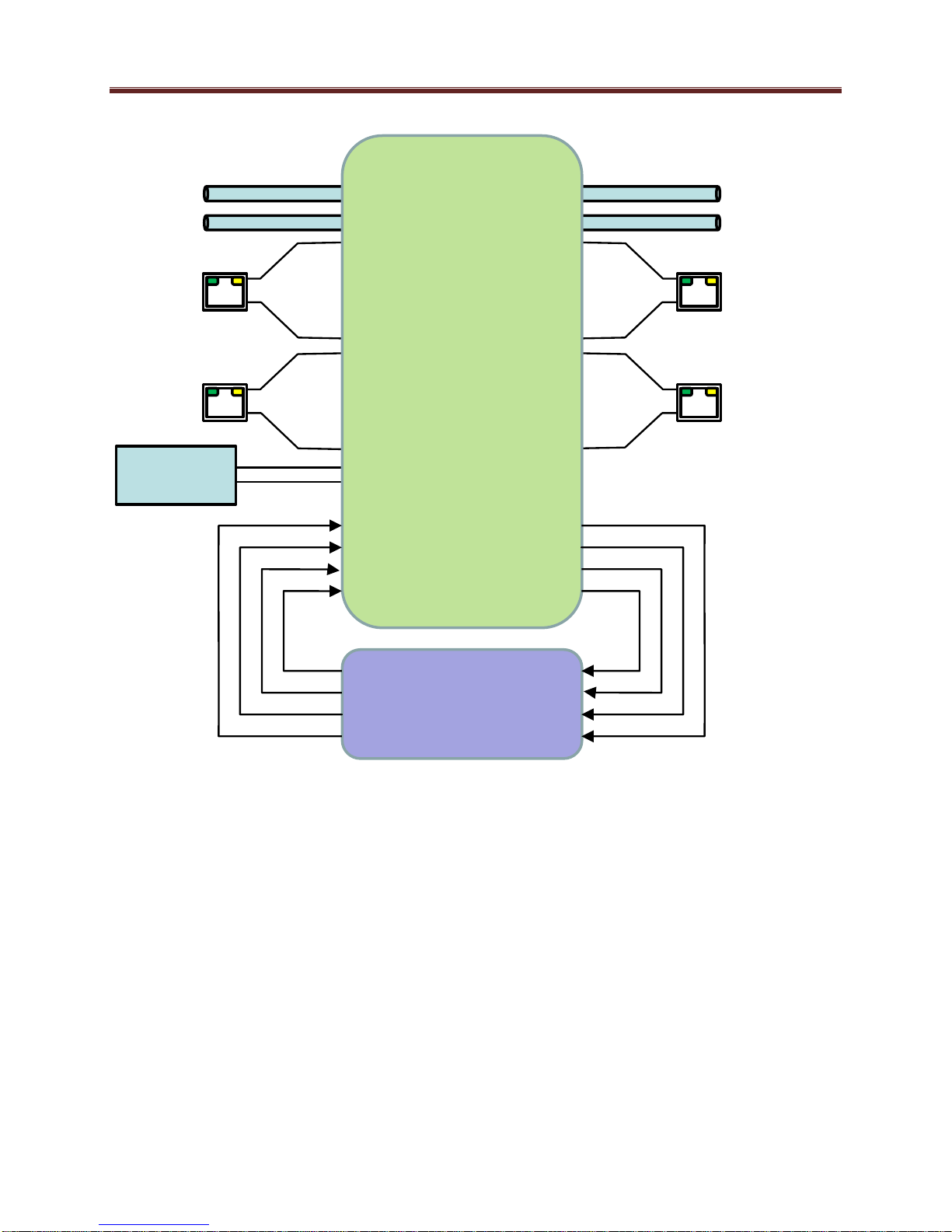
Test
Generators
ASI
ETH1
Up to 8
ETH2
Up to 8
ASI
ETH1
Up to 8
ETH2
Up to 8
Program
Router
Inputs
Outputs
4 x Audio/Video
Transcoders
For the remainder of this manual, we will use the term port for a physical input/output port (such
as ASI or Ethernet), and stream for a transport stream present in the port. ASI ports support only
one stream, while Ethernet ports support multiple streams. A transport stream can have one or
more programs. In this manual, we will use the words program and service interchangeably.
Redundancy Options
The IP inputs in the MVN-XC440 can be configured to support transport stream redundancy.
This means that the unit can be configured with a “primary transport” and a “backup transport”.
If the primary transport disappears, the unit may be set to automatically switch to the backup
transport, after a configurable timeout. The redundancy function has the following features:
Transport stream redundancy can be set to “Manual” or “Automatic”. In “Automatic”
mode, the unit will switch to the backup stream after a configurable timeout, if the
primary stream disappears. In “Manual” mode, the switch has to be performed by the
operator.
11

Regardless of the Automatic/Manual mode, the operator always has the ability to instruct
the unit to switch to the other transport stream.
An IP Input receives a transport stream over UDP/IP or RTP/UDP/IP, on a given IP
Address/UDP Port combination, with an optional Source IP address specification. For each IP
Input, the unit allows an optional backup IP Address/UDP Port/Optional Source IP Address
combination to be specified. If the transport stream disappears from the primary address/port
combination, the port can switch to the backup address/port combination (if configured for
automatic redundancy). The automatic switch timeout can be set to a value between 2 and 45
seconds.
This level of redundancy is available for all IP input ports, and is independent of any connections
that may exist to the port. It uses no internal resources in the MVN-XC440 (i.e., it does not
“count” as an input or as a connection), but it has the following limitations:
It is only available for IP input ports.
The primary and backup transport streams must be available on the same Ethernet port.
The MVN-XC440 does not monitor the inactive stream. Therefore, if the active stream
disappears and the other stream not running either, the MVN-XC440 will be switching
back and forth until one of the two streams comes back.
12

MVN-XC440 Indicators and Switches
The MVN-XC440 card can be installed in the 10-slot DFR-8310 frame, or in the 20-slot
DFR-8321 or OG-3 frames. Prior to installing the card, first install the corresponding rear panel
I/O module. Note that the rear I/O panel for the DFR-8321 and OG-3 frames is different from
the panel for the DFR-8310; if you have the wrong panel, please contact ImmediaTV to have it
replaced.
Rear I/O Panel Indicators
The MVN-XC440 rear I/O panel is depicted below. It includes 2 ASI inputs and 2 ASI outputs
on standard BNC connectors1, and two 100/1000 Mb/s Ethernet ports on standard RJ-45
connectors.
Each of the ASI input ports has a green indicator LED, with the following states:
LED off: ASI port is disabled.
LED flashing once every 3 seconds: the ASI port is not locked to a signal (i.e., there is
no input signal).
LED flashing once per second: the ASI port is is locked to a signal.
Each of the ASI output ports has a green indicator LED, with the following states:
LED off: ASI port is disabled.
LED flashing multiple times per second: ASI port is transmitting packets.
Each of the Gigabit Ethernet ports has two indicator LEDs, with the following states:
Green LED:
o Off: No link
o On: Link
Yellow LED:
o Off: No activity (transmit and/or receive)
o Flashing: Port is currently transmitting and/or receiving
1
The I/O panel has two unused BNC connectors.
13

ETH2
ASI2
ASI4
ASI6
ETH1
ASI1
ASI3
ASI5
ASI Inputs
ASI Outputs
Unused
Front Indicators
A similar set of indicators exist in the front of the board. These are visible when the frame front
door is opened. The indicator layout is depicted below.
The LED indicators are as follows:
Status LED: indicates the overall status of the board.
o Green: no active alarm
o Red: at least one critical alarm present
When inserting a board in the frame, this LED will be red until the board starts operation.
At that point, it will turn green if there is no active alarm or red if there is at least one
alarm.
Power OK LED: indicates that the power received from the frame is OK.
o Green: power OK
o Off: no power (or insufficient voltage – check the frame power status)
ASIRX 1 and ASIRX 2 LEDs: these behave exactly the same as the ASI input rear
I/O panel indicators (ASI 1 and ASI 2).
ASITX 1 and ASITX 2 LEDs: these behave exactly the same as the ASI output rear
I/O panel indicators (ASI 3 corresponds to ASITX 1 and ASI 4 corresponds to ASITX 2).
XC 1 and XC 2 LEDs: these LEDs flash if the unit is transcoding. XC 1 corresponds to
transcoder instances 1 and 2, and XC 2 corresponds to transcoder instances 3 and 4.
ETH1 and ETH2 LEDs: these indicate the status of the corresponding Ethernet
connection.
o Off: no link
o On: link OK, no activity
o Blinking: link OK, port is transmitting and/or receiving packets
14
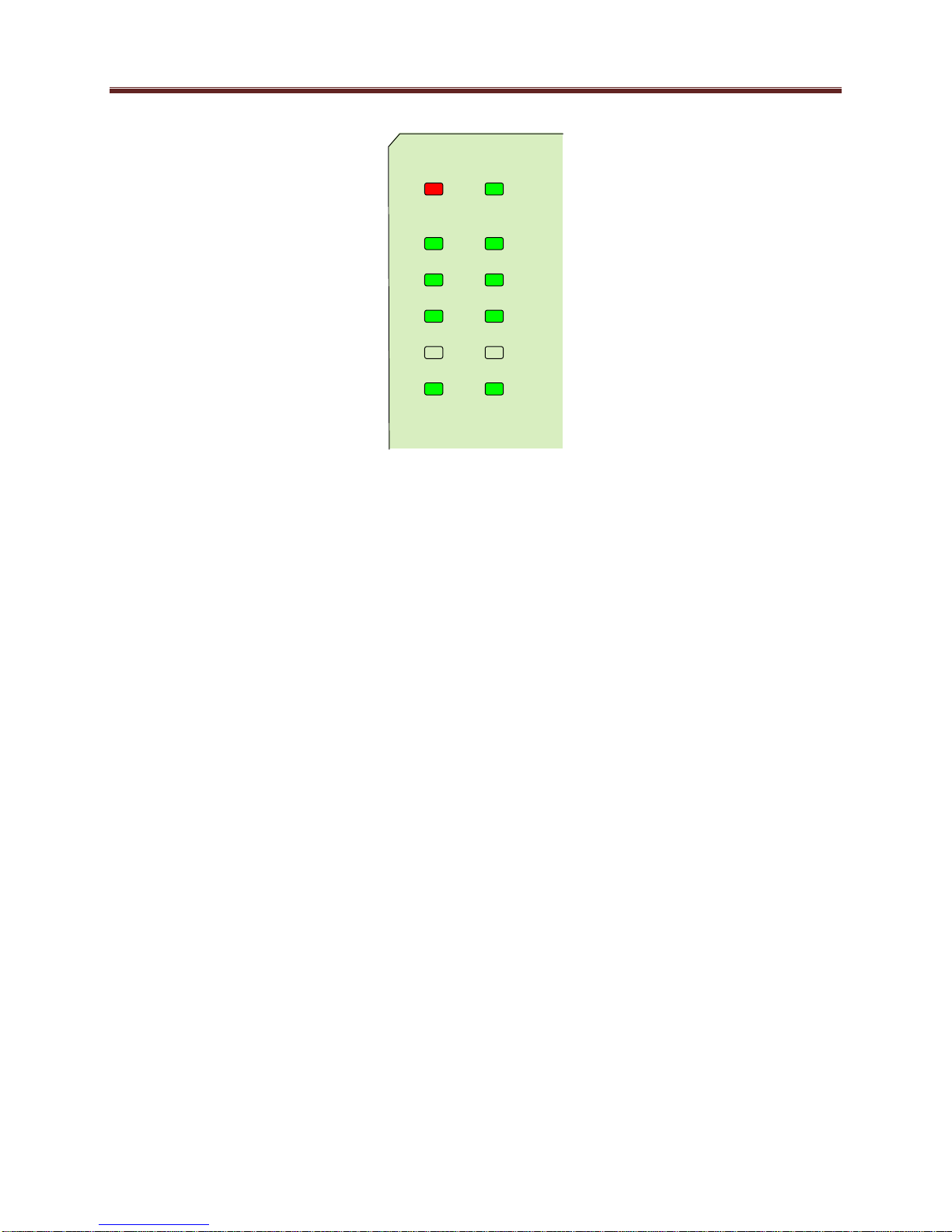
Status Power OK
ASIRX 2
ASITX 2
XC 2
ASIRX 1
ASITX 1
XC 1
ETH 2 ETH 1
Top Corner
The MVN-XC440 board has other LEDs that may or may not be illuminated. They are intended
for engineering debug only.
Front Switches
The MVN-XC440 board has two pushbutton-type switches in the front, just below the LEDs, as
depicted below. Their operation is as follows:
Default IP Switch: This switch is used to recover the board in the unlikely case of a
corrupted or broken firmware update. In most cases, the MVN-XC440 will detect the
error and automatically fall back into the factory-default firmware load. If it does not,
pull the card out, press and hold this switch, and push the card back into the frame while
still holding the switch. You can release the switch once the Status LED turns orange.
This action causes the card to revert to the factory-default firmware.
Reset Switch: Pressing this pushbutton switch causes the card to reset.
15
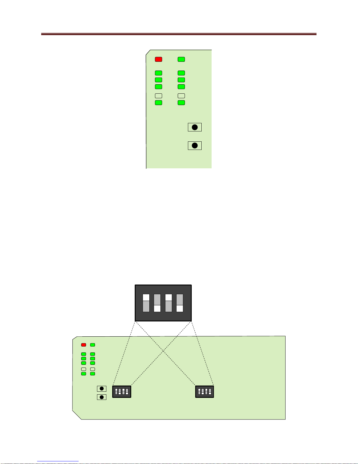
Default IP
Reset
Top Corner
Default IP
Reset
Top Corner
Top Corner
1 2 3 4
ON
DIP Switches
The MVN-XC440 has two DIP Switches. These are for ImmediaTV internal use only and their
settings must not be modified. If any changes are made to the DIP Switch settings, the
MVN-XC440 will stop operating. The correct settings for the two DIP Switches are:
1: ON
2: OFF
3: ON
4: OFF
These settings are illustrated below.
16
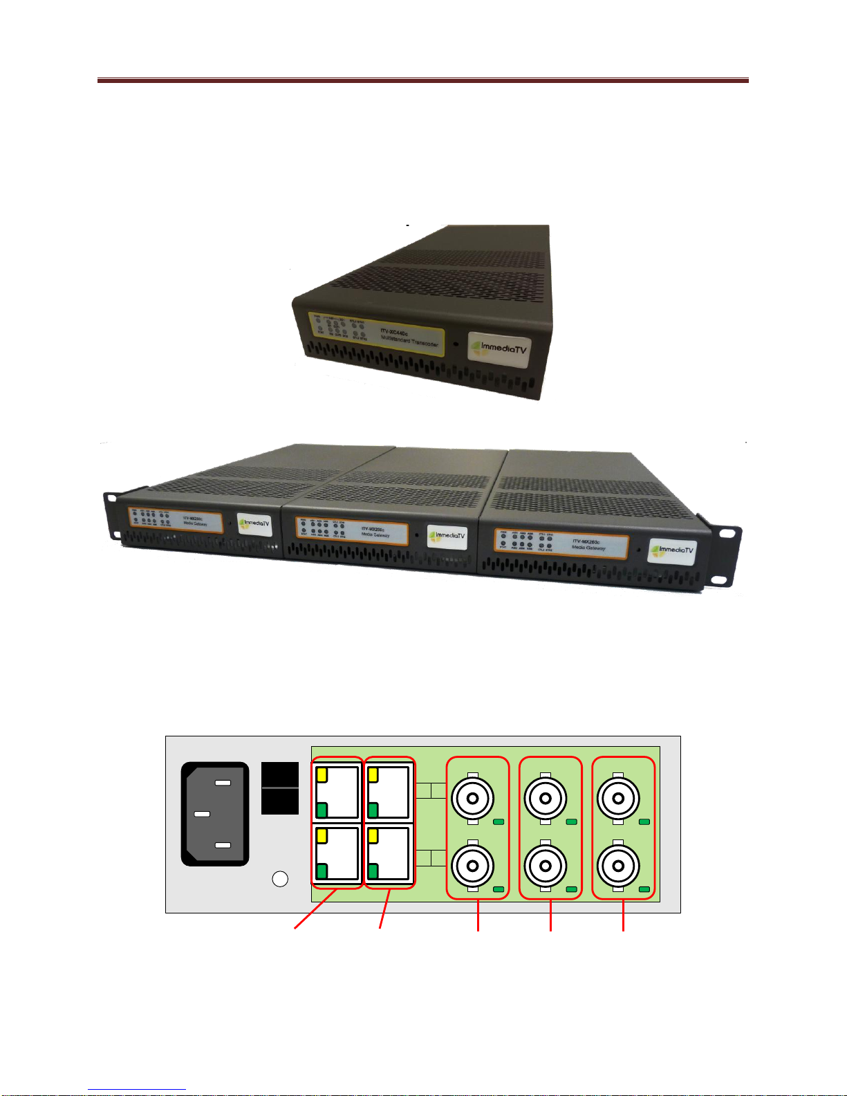
I
0
ASI2ASI4ASI6
ASI1ASI3ASI5
CTRL1 ETH1
CTRL2 ETH2
Streaming
Ethernets
Control
Ethernets
ASI
Inputs
ASI
Outputs
Unused
ITV-XC440c Indicators and Switches
The ITV-XC440c can be used as a desktop gateway, or in a 19” rack-mount tray that holds up to
three units:
Back Panel
The MVN-XC440 rear I/O panel is depicted below. It includes 2 ASI inputs and 2 ASI outputs
on standard BNC connectors, two streaming 100/1000 Mb/s Ethernet ports on standard RJ-45
connectors, and two control 10/100/1000 Mb/s Ethernet ports on standard RJ-45 connectors.
17

PWR
STAT
IN2 OUT2 XC2 CTL2 ETH2
ASI
XC1 CTL1 ETH1
IN1 OUT1
Each of the ASI input ports has a green indicator LED, with the following states:
LED off: ASI port is disabled.
LED flashing once every 3 seconds: ASI port is not locked to a signal (i.e., there is no
input signal).
LED flashing once per second: ASI port is locked to a signal.
Each of the ASI output ports has a green indicator LED, with the following states:
LED off: ASI port is disabled.
LED flashing multiple times per second: ASI port is transmitting packets.
Each of the Gigabit Ethernet ports has two indicator LEDs, with the following states:
Green LED:
o Off: No link
o On: Link
Yellow LED:
o Off: No activity (transmit and/or receive)
o Flashing: Port is currently transmitting and/or receiving
Front Panel Indicators
A similar set of indicators exist in the front panel of the unit. The layout is depicted below.
The front panel LED indicators are as follows:
STAT: indicates the overall status of the unit.
o Green: no active alarm
o Red: at least one critical alarm present
When powering up the unit, this LED will be red until the board starts operation. At that
point, it will turn green if there is no active alarm or stay red if there is at least one alarm.
PWR: indicates that the power is OK.
o Green: power OK
o Off: no power or insufficient voltage
ASI IN1 and IN2 LEDs: these behave exactly the same as the ASI input rear
I/O panel indicators (ASI 1 and ASI 2).
ASI OUT1 and OUT2 LEDs: these behave exactly the same as the ASI output rear
18

I/O panel indicators (ASI 3 corresponds to ASITX 1 and ASI 4 corresponds to ASITX 2).
XC 1 and XC 2 LEDs: these LEDs flash if the unit is transcoding. XC 1 corresponds to
transcoder instances 1 and 2, and XC 2 corresponds to transcoder instances 3 and 4.
ETH1/2 and CTL1/2: these indicate the status of the corresponding Ethernet connection.
o Off: no link
o On: link OK, no activity
o Blinking: link OK, port is transmitting and/or receiving packets
Front Panel Default Switch
The front panel has a recessed switch that can be used to restore the unit to its defaults. Use a
pen or a small screwdriver to press this switch.
If the switch is pressed during normal operation, the control port IP address, mask and gateway
are restored to the following factory default settings:
IP Address: 192.168.1.30
Subnet Mask: 255.255.255.0
Gateway: 192.168.1.1
The STAT front panel indicator will change colors for about 3 seconds to acknowledge the
change. Note that this operation does not disturb the encoding function or the streaming
Ethernet ports (i.e., it is not service-affecting).
If you press and hold this switch when the unit is powered off, and then power up the unit while
holding the switch, the following actions will be performed:
The control IP address, mask and gateway are reset to the factory defaults as described
above.
The unit configuration is cleared.
19

The unit reverts to the factory-installed firmware.
As before, the STAT LED will temporarily change color to acknowledge the command. When it
changes color, you can release the switch. You can use this feature in the unlikely event of a
corrupted firmware upgrade or a corrupted configuration.
20

MVN-XC440/ITV-XC440c Operation and Management
The MVN-XC440 is configured using the free Dashboard™ application, which is available for
Windows, Apple OS X, and Linux. Dashboard can be downloaded from this link:
http://www.opengear.tv/?p=94
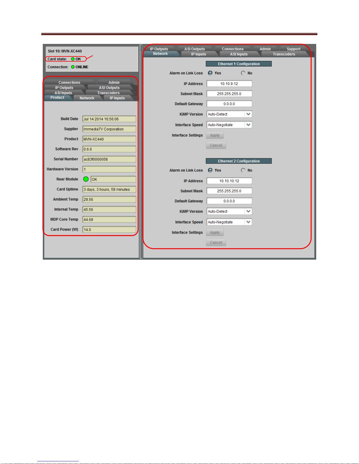
The MVN-XC440 user interface is depicted below. As with any openGear™ card, it is divided
into a statistics panel on the left, and a configuration panel on the right. Each panel has multiple
tabs, corresponding to the various functions in the card. Note that the Card State alarm
indicator is also reflected in the green/red Status LED in the front of the board. The Status LED
will be green when Card State is green or yellow, and will be red when Card State is red.
The following tabs are available:
Product: this tab provides general information on the card, including firmware version,
uptime, temperatures, and other parameters. It appears only on the Statistics panel.
Network: this tab is used to configure the IP addresses and network information for the
Ethernet ports. The statistics side of the panel includes some additional information such
as link state.
ASI Inputs: this tab is used to configure/monitor the ASI Input ports.
ASI Outputs: this tab is used to configure/monitor the ASI Output ports.
IP Inputs: this tab is used to configure/monitor the IP Input ports. The configuration
panel provides the facilities to create, manage and delete ports; the statistics panel
includes reception status information.
IP Outputs: this tab is used to configure/monitor the IP Output ports. The configuration
panel provides the facilities to create, manage and delete ports; the statistics panel
includes transmission status information.
Transcoders: this tab is used to configure/monitor the transcoder instances. The
configuration panel provides facilities to configure each transcoder instance, and the
statistics panel provides status information.
Connections: this tab is used to configure connections. It provides facilities to create,
edit and delete connections; the statistics panel provides a table where the status of all the
connections in the unit can be inspected at a glance.
Admin: this tab is used for general administrative functions, such as firmware upgrades,
licensing, logs, and configuration management. The Test Packet Generator configuration
is also found under this tab.
Support: this tab has information on how to contact ImmediaTV Customer Support, and
has the ability to generate a tech support dump for the unit. When contacting
ImmediaTV for support, always include the support dump from this tab.
21
Statistics Panel
Configuration Panel
Reflected in the
front Status LED
22
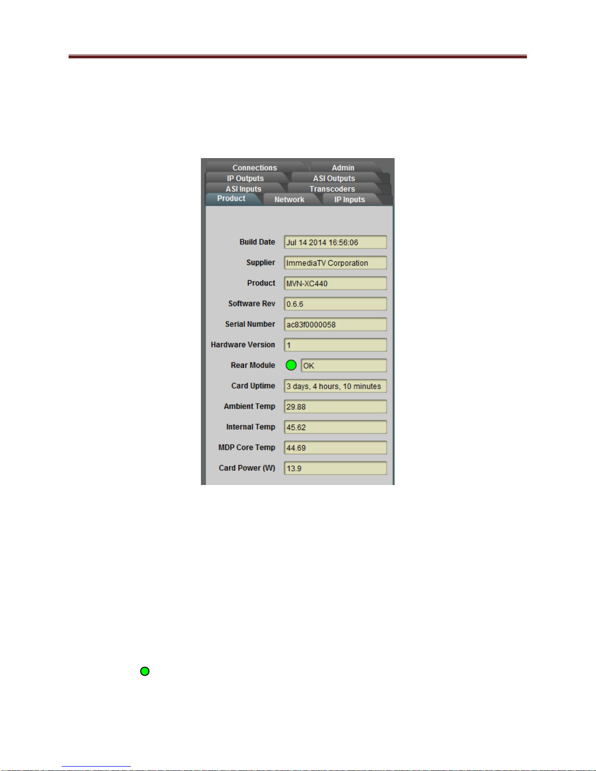
Product Tab
The Product Tab contains basic information about the MVN-XC440.
The following information is available:
Build Date: Date the firmware image was built.
Supplier: ImmediaTV Corporation.
Product: MVN-XC440 or ITV-XC440c.
Software revision: This indicates the firmware revision currently running. The format is
Major Version Minor Version Build Number.
Serial Number: This is the serial number of this particular MVN-XC440 card.
Hardware Version: This indicates the board version number. All board versions are
functionally equivalent.
Rear Module: This indicates the status of the Rear I/O Module. It can have one of the
following states:
o OK: The Rear Module is the correct module for the MVN-XC440. In the
ITV-XC440c this indicator will always indicate OK.
23

o Not Installed: The MVN-XC440 is not connected to a rear module. The card
is operating normally, but it will not be useful as there are no input and output
connections to it.
o Wrong Module: The MVN-XC440 is connected to a rear module that was not
designed for it (most likely from another openGear™ vendor). Depending on the
signals present on that module, there may be a small chance of damage to the
MVN-XC440; ImmediaTV recommends that this situation be rectified
immediately. This alarm will cause the front status LED to turn red.
Card Uptime: Indicates how long the card has been running since it was last rebooted.
Ambient Temperature: Temperature, in degrees centigrade, of the air intake of the card
(measured at the front edge of the card).
Internal Temperature: Temperature, in degrees centigrade, at the back of the card.
MDP Core Temperature: Temperature, in degrees centigrade, of the core processing
element.
Card Power (W): Indicates the current power draw of the unit, in watts.
The openGear™ frame is designed to operate in environments with up to 40oC ambient. There is
typically a 5
measured by the MVN-XC440. If that measurement is at 45oC or higher, action must be taken to
cool down the ambient temperature. The MVN-XC440 will log excessive temperature events.
o
C temperature raise from the external ambient to the “Ambient Temperature”
24
Network Tab
The Network Tab allows for configuration/monitoring of the two Ethernet ports.
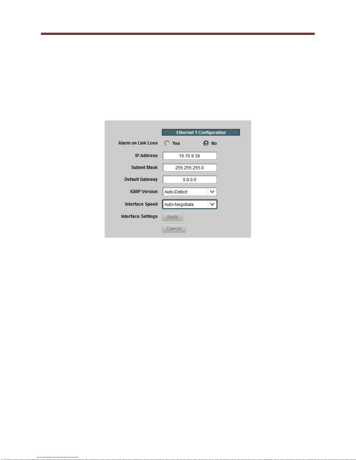
Network Configuration Tab
The Network Configuration Tab is used to set the individual parameters for each of the Ethernet
ports.
The following parameters can be configured:
Alarm on Link Loss: If set to Yes, the card will raise an alarm if this Ethernet interface
loses link. The Card State indicator in Dashboard™ and the front Status LED will both
be red. If set to No, the card will still report loss of link in the Statistics page but no
alarm will be raised. ImmediaTV recommends turning on the alarm for ports that are in
use; only turn it off if you do not plan to connect that port to a network.
IP Address: Enter the desired IP address for this Ethernet port. Please note that the
MVN-XC440 uses a block of 4 IP addresses for internal communication; these addresses
cannot be used for the external network interfaces. The reserved addresses are:
o 10.253.254.252
o 10.253.254.253
o 10.253.254.254
o 10.253.254.255
Please contact ImmediaTV Corporation if this is an issue for your network.
Subnet Mask: Enter the desired subnet mask for this Ethernet port.
Default Gateway: Enter the desired default gateway for this Ethernet port, or 0.0.0.0 if
no gateway is available.
Interface Settings: If you make any changes to the IP Address, Subnet Mask and/or
Default Gateway fields, the Apply and Cancel buttons become active. The changes only
take effect when you press the Apply button. Pressing the Cancel button reverts the
25
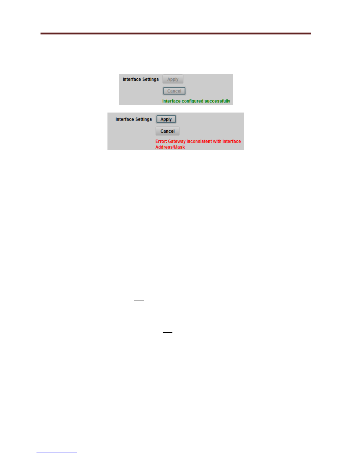
fields back to their original values. Note that the MVN-XC440 will check the
consistency of the data entered and will reject invalid combinations. Once the Apply
button is pressed, a status message appears just below the Cancel button, as follows:
IGMP Version: The MVN-XC440 implements the IGMP protocol for multicast
reception. This parameter controls the version of the protocol to be used.
o Auto-Detect: The MVN-XC440 will attempt to auto-detect the IGMP version in
use by inspecting the Group Membership Requests received from the router. It
defaults to IGMP Version 3 if no messages are received.
o IGMP Version 1: Force the use of Version 1 only (not recommended)
o IGMP Version 2: Force the use of Version 2 only
o IGMP Version 3: Force the use of Version 3 only
Interface speed: Configures the speed of the interface. The MVN-XC440 Ethernet
interfaces only support two modes: 100 Mb/s Full-Duplex and 1 Gb/s Full-Duplex2.
o Auto-Negotiate: The Ethernet port will auto-negotiate the speed.
o 100 Mb/s Full-Duplex: Force the port to 100Mb/s Full-Duplex mode. Note that
the port will still perform auto-negotiation, but it will only advertise this mode.
o 1Gb/s Full-Duplex: restrict the operation to 1Gb/s Full-Duplex mode. Note that
the port will still perform auto-negotiation, but it will only advertise this mode.
Notes:
o If the MVN-XC440 streaming Ethernet interfaces are connected to a 10 Mb/s switch, hub,
or network feed, link will not be established and the port will not recognize the
connection.
o If you select 100 Mb/s Full-Duplex or 1 Gb/s Full-Duplex and the corresponding
streaming Ethernet interface is connected to a switch, hub or network feed that does not
support the selected speed, link will not be established and the port will not recognize the
connection.
o If the interface speed is set to Auto-Negotiate, the streaming Ethernet port will allow link
to be established in 100 Mb/s Half-Duplex mode. However, this will be flagged as a
warning in the Network Statistics Tab and in the Admin Event Log Tab.
2
ImmediaTV has disabled support for 10 Mb/s and Half-Duplex modes, as these are unsuitable for MPEG transport
over IP applications. Moreover, any modern switch supports at least 100 Mb/s Full-Duplex.
26
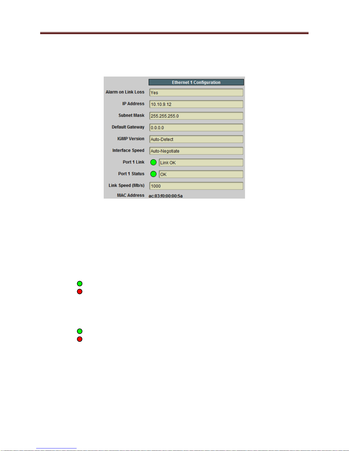
Network Statistics Tab
The Network Statistics Tab reports the current IP configuration of each Ethernet port, as well as
their link state and running status.
The following parameters are reported in the Network Statistics tab:
Alarm on Link Loss: Reports the current setting of this parameter.
IP Address: Reports the current IP Address for the port.
Subnet Mask: Reports the current Subnet Mask for the port.
Default Gateway: Reports the current Default Gateway for the port.
IGMP Version: Reports the current setting for this parameter.
Interface Speed: Reports the current setting for this parameter.
Port 1/2 Link: This indicator has the following states:
o Link OK: The port has established link with the switch.
o No Link: The port does not currently have link. If Alarm on Link Loss is set to
Yes, the Dashboard™ Card State will be red and the Status LED in the front of the
board will also be red. If Alarm on Link Loss is set to No, this indicator will still be
red, but the alarm will not propagate.
Port 1/2 Status: This indicator is the port overrun status. It has the following states:
o OK: The port is operating normally.
o TX Overflow: In the current configuration, the IP outputs are attempting to
transmit more than the port capacity (i.e., the overall output data for this port
exceeds the interface speed of 100 Mb/s or 1 Gb/s). The Dashboard™ Card State
will be red and the Status LED in the front of the board will also be red. In this case,
reduce the output bit rate (either by externally controlling the inputs or by removing
output ports). If this indicator is red, data is being dropped.
Link Speed (Mb/s): This parameter reports the actual speed negotiated with the switch
for the port. If the port has no link, the value reported here is zero.
MAC Address: This reports the MAC address of the Ethernet port.
27

ASI Input Ports
The MVN-XC440 card has 2 fixed-function ASI Input Ports. This tab is used to configure and
manage these ports.
ASI Inputs: Configuration Tab
The Configuration Tab for the ASI inputs is shown below:
As indicated in the picture, two bottom tabs are available:
Configuration: this tab provides some basic statistics for the ports and allows for
configuration of the ASI input parameters.
Program Info: if the ASI input is receiving a transport stream, this tab provides
information about the programs found in that transport stream.
ASI Inputs: Configuration
The Configuration tab is divided into two areas:
The ASI Inputs table, which displays an overview of the ports. It contains the following
fields:
o Status: Indicates the current status of the port. The possible values are:
Locked: the port is enabled and locked to a valid ASI signal.
Unlocked: the port is enabled, but has no signal.
Disabled: the port is disabled by user configuration.
o Size: Indicates the detected ASI transport packet size (188 or 204 bytes). If the
port is disabled or unlocked, this field will show a value of 0 (zero).
o TS Bit Rate (b/s): Measured transport stream bit rate, in bits/second.
28
 Loading...