

ImmediaTV MVN-IP360, ITV-IP360d, ITV-IP360c User Manual

MVN-IP360 openGear® Encoder
ImmediaTV
ITV-IP360c Standalone Encoder
ITV-IP360d Standalone Encoder
User Manual
Version 2.4

Copyright
© 2011-2015 ImmediaTV Corporation. All rights reserved.
Contents of this publication may not be reproduced in any form without the written permission
of ImmediaTV.
Notice
The material in this manual is furnished for informational use only, and it is subject to change
without notice. It must not be construed as a commitment by ImmediaTV. ImmediaTV assumes
no responsibility or liability for errors or inaccuracies that may appear in this manual.
Trademarks
DashBoard Control System™ is a trademark of Ross Video Limited.
openGear® is a trademark of Ross Video Limited.
Apple® Mac OS®, Leopard®, and Snow Leopard™ are trademarks of Apple Computer,
Inc., registered in the U.S. and other countries.
Microsoft®, Internet Explorer®, and Windows® are either registered trademarks or
trademarks of Microsoft Corporation in the U.S.A. and/or other countries.
Linux® is the registered trademark of Linus Torvalds in the U.S. and other countries.
Flash® is the registered trademark of Adobe in the US and other countries.
All other product names and any registered and unregistered trademarks mentioned in
this guide are used for identification purposes only and remain the exclusive property of
their respective owners.
Environmental Information
The equipment that you purchased required the extraction and use of natural resources for its
production. It may contain hazardous substances that could impact health and the environment.
To avoid the potential release of those substances into the environment and to diminish the need
for the extraction of natural resources, ImmediaTV encourages you to use the appropriate takeback systems. These systems will reuse or recycle most of the materials from your end-of-life
equipment in an environmentally friendly and health conscious manner.
If you need more information on the collection, reuse, and recycling systems, please contacts
your local or regional waste administration.
2

Company Address
ImmediaTV Corporation
2005 De La Cruz Boulevard, Suite 150
Santa Clara CA 95050
USA
Telephone +1 408 496 1256
E-mail (Technical Support): support@immediatv.com
E-mail (General Information): sales@immediatv.com
Website: http://www.immediatv.com
3

Contents
Copyright ........................................................................................................................................ 2
Notice .............................................................................................................................................. 2
Trademarks ..................................................................................................................................... 2
Environmental Information ............................................................................................................. 2
Company Address ........................................................................................................................... 3
Contents .......................................................................................................................................... 4
Safety Instructions for the ITV-IP360c/d Appliance ...................................................................... 6
Electrostatic Discharge (ESD) and ESD Protection ................................................................... 6
Safety Notice and Warnings ....................................................................................................... 6
FCC Notice ............................................................................................................................. 6
Other Certifications ................................................................................................................. 6
CE Mark Warning ................................................................................................................... 7
Installation Safety Notes ............................................................................................................. 7
Introduction ..................................................................................................................................... 9
Product Overview ..................................................................................................................... 10
MVN-IP360 Indicators and Switches ........................................................................................... 11
Rear I/O Panel Indicators .......................................................................................................... 11
Front Indicators ......................................................................................................................... 12
Front Switches .......................................................................................................................... 13
ITV-IP360c Indicators and Switches ............................................................................................ 15
Back Panel ................................................................................................................................ 15
Front Panel Indicators ............................................................................................................... 17
Front Panel Default Switch ....................................................................................................... 17
ITV-IP360d Indicators and Switches ............................................................................................ 19
Back Panel ................................................................................................................................ 19
Front Panel Indicators ............................................................................................................... 21
The Presets Menu .................................................................................................................. 22
The Config Menu .................................................................................................................. 23
The Status Menu ................................................................................................................... 23
MVN-IP360/ITV-IP360c/d Operation and Management ............................................................. 24
Product Tab ................................................................................................................................... 26
Network Tab ................................................................................................................................. 28
Network Configuration Tab ...................................................................................................... 28
Network Configuration Interfaces Tab ................................................................................. 28
Network Configuration DNS Tab ......................................................................................... 29
Network Statistics Tab .............................................................................................................. 30
Network Statistics Interface Tab ........................................................................................... 30
Network Statistics DNS Tab ................................................................................................. 31
Encoder 1, Encoder 2 Tabs ........................................................................................................... 32
Encoder Configuration Tab ....................................................................................................... 32
Video Input Auto-Detection ................................................................................................. 33
Encoder Basic Configuration Tab ......................................................................................... 33
Basic Tab – General Configuration .................................................................................. 34
Basic Tab – Video Configuration ..................................................................................... 35
4

Basic Tab – Audio Configuration ..................................................................................... 39
Encoder Advanced Configuration Tab ................................................................................. 41
Advanced Tab – Video Parameters................................................................................... 41
Advanced Tab – VBI/Ancillary Data Insertion ................................................................ 43
Advanced Tab – Audio Parameters .................................................................................. 47
Advanced Tab – Mux Parameters ..................................................................................... 49
Encoder Output Tab .............................................................................................................. 52
UDP/IP Streaming ............................................................................................................ 53
HTTP Live Streaming ....................................................................................................... 54
Direct HTTP Streaming .................................................................................................... 59
RTMP ................................................................................................................................ 60
The Apply/Cancel Buttons .................................................................................................... 63
Encoder Statistics Tab............................................................................................................... 64
Encoder Status ...................................................................................................................... 65
Output Status ......................................................................................................................... 69
Admin Tab .................................................................................................................................... 72
Admin General Tab................................................................................................................... 72
Admin Firmware Tab ................................................................................................................ 73
Admin Config Files Tab ........................................................................................................... 75
User-Saved Configurations ................................................................................................... 75
Pre-defined Templates .......................................................................................................... 77
Clear Current Configuration Button ..................................................................................... 78
Admin Event Log Tab .............................................................................................................. 78
Support Tab ................................................................................................................................... 82
Control Tab ................................................................................................................................... 83
Control Port Configuration Tab ................................................................................................ 83
Control Port Statistics Tab ........................................................................................................ 84
SNMP Configuration Tab ......................................................................................................... 85
SNMP Statistics Tab ................................................................................................................. 86
Playing Video on a Web Page ...................................................................................................... 87
Web Pages Served by the IP360 ............................................................................................... 88
Multicast Streaming .............................................................................................................. 90
HTTP Live Streaming ........................................................................................................... 90
Direct HTTP Streaming ........................................................................................................ 91
Using a Firewall between the IP360 and the Internet ........................................................... 92
Web Browser Support ........................................................................................................... 93
5

CAUTION: To reduce the risk of electric shock, do not open chassis; do
not defeat or remove the ground pin of the power cord; connect only to
a properly grounded ac power outlet. No user-serviceable parts inside.
Refer servicing to qualified service personnel.
Safety Instructions for the ITV-IP360c/d Appliance
The ImmediaTV ITV-IP360c/d appliance is turned off by using the power switch. Power may
still be present in the appliance. To ensure that the appliance is completely shut down, unplug its
power cord from its power source.
The ImmediaTV ITV-IP360c/d appliance ships with all required components installed. There is
no need to open the chassis to add or remove components. Please contact ImmediaTV regarding
any malfunction or failure of the ImmediaTV appliance.
Electrostatic Discharge (ESD) and ESD Protection
Static electricity can damage boards, and other components. Before connecting or disconnecting
any device to the ImmediaTV ITV-IP360c/d appliance, we recommend you discharge static
electricity by first touching a metal part of a grounded PC.
Safety Notice and Warnings
FCC Notice
This device complies with Subpart B of Part 15 of the FCC Rules. Operation is subject to the
following two conditions:
This device may not cause harmful interference.
This device must accept any interference received, including interference that may cause
undesired operation.
No Telecommunications Network Voltage (TNV)-connected PCBs shall be installed.
Other Certifications
This class A digital apparatus complies with Canadian ICES-003, Issue 4.
Cet appareil numérique de la classe A est conforme à la norme NMB-003 du Canada.
This device complies with EN 55022 standards.
This device complies with EN 61000-3-2 standards.
This device complies with EN 61000-4-2 standards.
This device complies with CISPR 22 Edition 6.
This device complies with AS/NZS CISPR 22.
6

Important Safety Information! Please note the following:
1. The ImmediaTV ITV-IP360c/d is intended for indoor use only.
2. In case of emergency, disconnect the power cords.
3. If power cords are not provided:
In the United States, use standard computer power cords (as
specified below).
In Europe, for 230 volt operation, use a cord set marked “HAR”
and consisting of a min 3 core H05VVF3G075 cord that has a
minimum 0.75 square mm diameter conductors, provided with
an IEC 320 receptacle and a male plug for the country of
installation, rated 6A, 250V.
4. Do not block the equipment vents.
CE Mark Warning
This is a Class A product. In a domestic environment, this product may cause radio interference,
in which case the user may be required to take adequate measures.
Installation Safety Notes
Do not place the ImmediaTV ITV-IP360c/d appliance underneath heavy loads or in an
unstable position.
Do not expose the ImmediaTV ITV-IP360c/d appliance under direct sunlight, high
humidity or wet conditions.
Do not use or expose the ImmediaTV ITV-IP360c/d appliance around magnetic fields as
magnetic interference may affect the performance of the device.
Do not block the air vents to this device or impede the airflow in any way.
READ THE FOLLOWING SAFETY INFORMATION THOROUGHLY BEFORE
INSTALLING THIS IMMEDIATV PRODUCT. FAILURE TO FOLLOW THIS SAFETY
INFORMATION MAY LEAD TO PERSONAL INJURY OR DAMAGE TO THE
EQUIPMENT.
Power Supply
This unit must be grounded.
The unit must be connected to a grounded outlet to comply with product safety standards.
The grounded socket-outlet shall be installed near the equipment and shall be easily
accessible.
Do not connect the power supply unit to an AC outlet without a ground connection.
All power cords must be disconnected before servicing.
Power Cords
The plug on the power supply cords is considered to be the equipment disconnect device and
must be approved for the country where it is used.
7

For USA and Canada:
The cord set must be UL-approved and CSA-certified.
The attachment plug must be an earth-grounding type with a NEMA 5-15P (15A 125V)
plug and an EN60320/IEC320 receptacle.
8

Introduction
This manual covers the following products:
The MVN-IP360 openGear® H.264 SD/HD single and dual-channel encoder card
The ITV-IP360c standalone H.264 SD/HD single and dual-channel encoder appliance
The ITV-IP360d standalone H.364 SD/HD single and dual-channel encoder appliance
All products have the same set of features, and essentially the same user interface. Unless
specifically indicated, all features and controls described in this manual apply to all products.
The encoders have the following features:
Video Encoding support: up to two channels of SD or HD H.264 encoding, with a
maximum resolution of 19201080p60 per channel.
Audio Encoding support: up to two channels of MPEG-1 Layer II or AAC-LC.
Video Inputs: support for composite, SD-SDI, HD-SDI, and 3G-SDI.
Audio Inputs: support for balanced or unbalanced analog audio, and SDI embedded
digital audio.
Outputs: 2 Ethernet ports, supporting 100 Mb/s and 1 Gb/s operation.
Replication: each encoded stream can be replicated on both Ethernet port.
Support for UDP/RTP on Ethernet.
Support for Over-The-Top (OTT) protocols: HTTP Live Streaming, RTMP, Direct HTTP.
Closed-Captioning support (both EIA-608 and EIA-708 captions).
AFD extraction and insertion support.
Support for pre-compressed Dolby AC-3 pass-through embedded in SDI inputs.
Support for SCTE-104 to SCTE 35 conversion.
The ITV-IP360c/d includes two additional Ethernet ports for control and management.
Typical application scenarios for the IP360 are:
Video Distribution over IP backbones
IPTV headends
Monitoring
High-Quality OTT generation
9
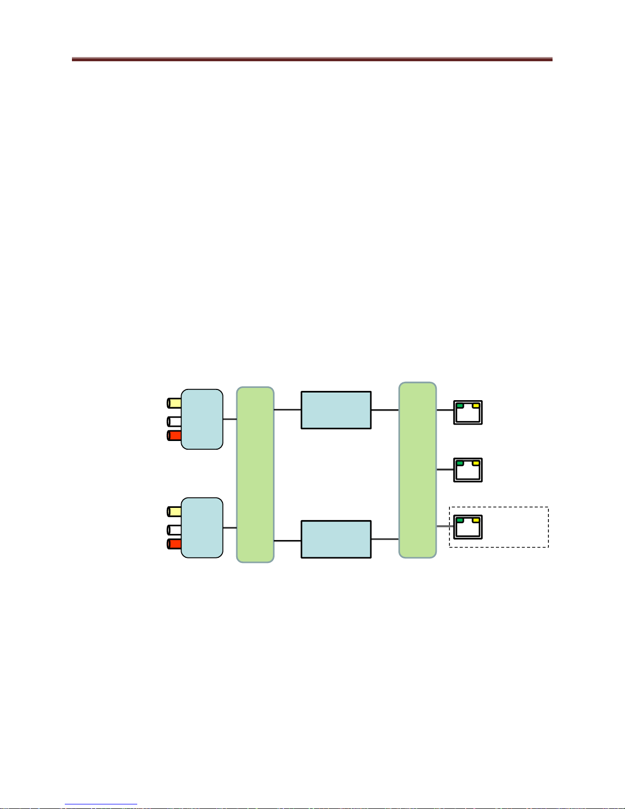
Inputs
Outputs
ETH1
ETH2
A/V
1
Composite/SDI
Unbalanced
Audio
Switch
A/V
2
Composite/SDI
Unbalanced
Audio
Encoder
1
Encoder
2
Protocol Processor
Control
ITV-IP360c/d only
Product Overview
The MVN-IP360/ITV-IP360c/d supports up to two H.264 SD/HD encoders each with one stereo
pair of audio encoding. The encoded transport stream can be routed and replicated to both
Ethernet ports.
The following inputs are available:
Software-configurable Composite or SDI video inputs, with auto-detection capability
SDI video inputs support SD-SDI, HD-SDI and 3G-SDI, with auto-detection capability
Analog unbalanced audio stereo inputs
SDI embedded audio support
The following outputs are available:
Two Ethernet outputs, supporting full-duplex 100 Mb/s and 1 Gb/s operation
A block diagram of the encoder is shown below:
10

1
MVN-IP360 Indicators and Switches
The MVN-IP360 card can be installed in the 10-slot DFR-8310 frame, or in the 20-slot
DFR-8321 or OG3-FR frames. Prior to installing the card, first install the corresponding rear
panel I/O module. Note that the rear I/O panel for the DFR-8321 and OG3-FR frames is
different from the panel for the DFR-8310; if you have the wrong panel, please contact
ImmediaTV to have it replaced1.
Rear I/O Panel Indicators
There are two rear I/O panels available for the MVN-IP360 encoder, to support different analog
audio inputs:
Unbalanced Audio I/O Panel
Balanced Audio I/O Panel
All MVN-IP360 I/O panels have two software-configurable Composite/SDI video inputs on
standard BNC connectors and two 100/1000 Mb/s Ethernet ports on standard RJ-45 connectors.
There also two unused BNC ports. The unbalanced audio I/O panel includes four RCA
connectors, and the balanced audio I/O panel includes four terminal blocks. The panels are
depicted in the next page.
Each of the video inputs has a green indicator LED, with the following states:
LED off: no video signal detected, or input not configured.
LED flashing: video input locked to the video signal.
o LED flashing about once per second: input video is SD.
o LED flashing about twice per second: input video is HD-SDI.
o LED flashing about 4 times per second: input video is 3G-SDI (1080p60).
Each of the Gigabit Ethernet ports has two indicator LEDs, with the following states:
Green LED:
o Off: No link
o On: Link
Yellow LED:
o Off: No activity (transmit and/or receive)
o Flashing: Port is currently transmitting and/or receiving
The Balanced Audio I/O panel is not available for the 10-slot DFR-8310.
11
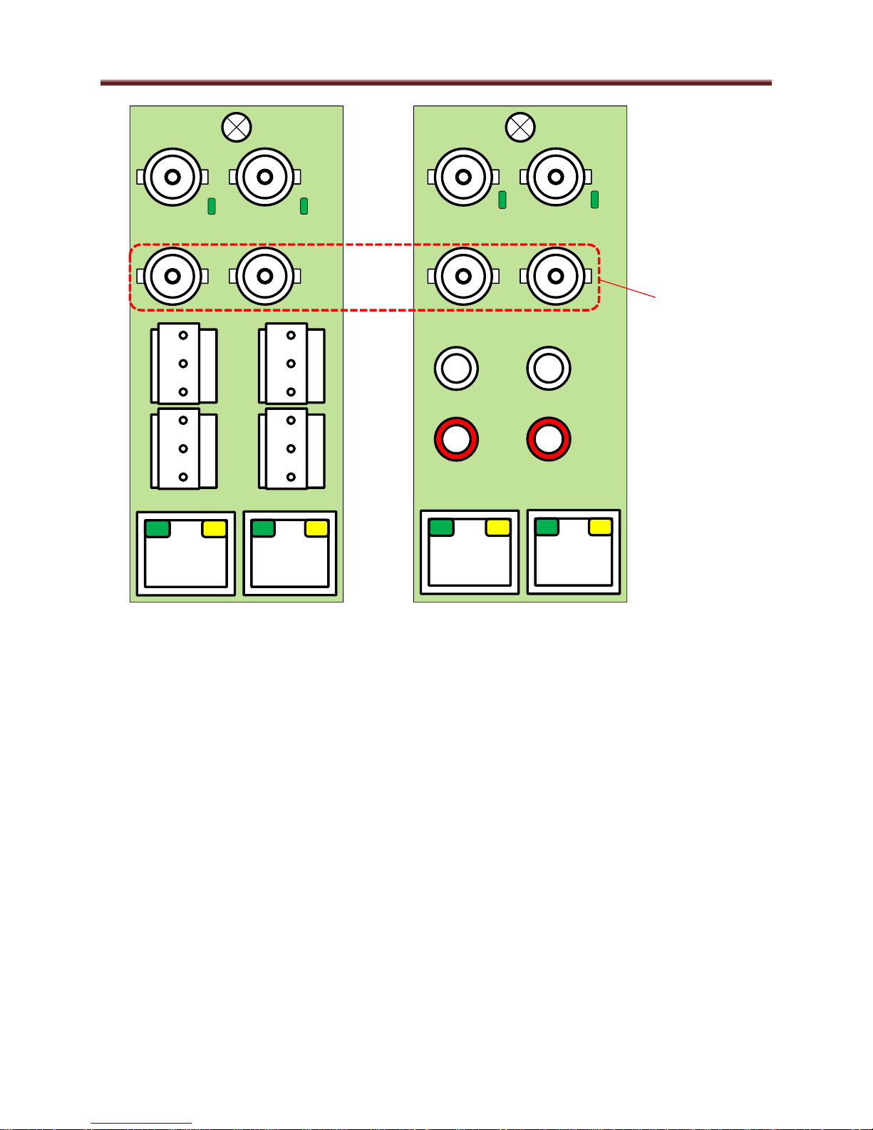
ETH1
AUD1
RT
AUD1
LFT
ETH2
AUD2
RT
AUD2
LFT
VID2
VID1
ETH1
ETH2
G
_
+
G
_
+
G
_
+
G
_
+
L AUD1 R
L AUD2 R
VID2
VID1
Balanced Audio
Unbalanced Audio
Unused
Ports
Note that the balanced audio rear I/O panel is only supported boards with hardware version 4 and
higher. The hardware version is available in the Product Tab in DashBoard.
Front Indicators
A similar set of indicators exist in the front of the board. These are visible when the frame front
door is opened. The indicator layout is depicted below.
The LED indicators are as follows:
Status LED: indicates the overall status of the board.
Power OK LED: indicates that the power received from the frame is OK.
o Green: no active alarm
o Red: at least one critical alarm present
When inserting a board in the frame, this LED will be red until the board starts operation.
At that point, it will turn green if there is no active alarm or stay red if there is at least one
alarm.
o Green: power OK
12
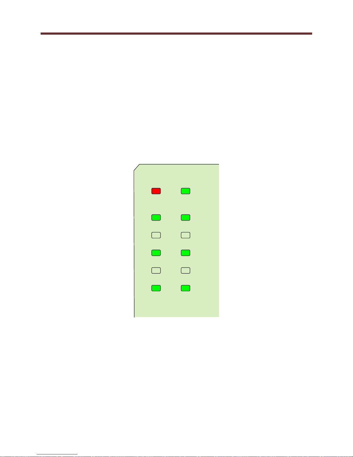
Status Power OK
VID 2
ENC 2
VID 1
ENC 1
ETH 2 ETH 1
Top Corner
o Off: no power (or insufficient voltage – check the frame power status)
VID 1 and VID 2 LEDs: these behave exactly the same as the corresponding rear I/O
panel indicators.
ENC1 and ENC2 LEDs: these LEDs flash if the corresponding encoder is running, with
output available for routing to ASI, UDP or RTP. They will not flash if the encoder is
stopped (either by explicit configuration or by lack of input) or if it is in one of the Web
streaming modes (HTTP Live Streaming or Direct HTTP Streaming).
ETH1 and ETH2 LEDs: these indicate the status of the corresponding Ethernet
connection.
o Off: no link
o On: link OK, no activity
o Blinking: link OK, port is transmitting and/or receiving packets
The MVN-IP360 board has other LEDs that may or may not be illuminated. They are intended
for engineering debug only.
Front Switches
The MVN-IP360 board has two pushbutton-type switches in the front, just below the LEDs, as
depicted below. Their operation is as follows:
Default IP Switch: This switch is used to recover the board in the unlikely case of a
corrupted or broken firmware update. In most cases, the MVN-IP360 will detect the
13
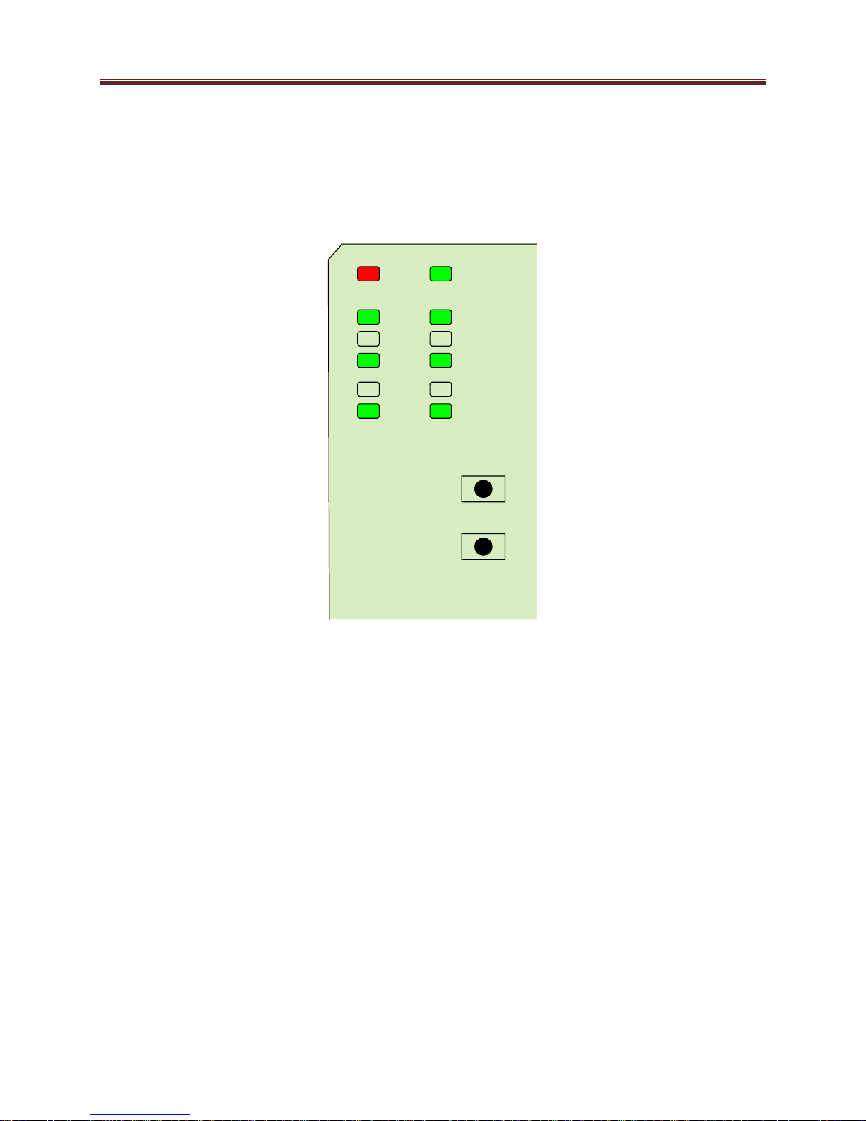
Default IP
Reset
Top Corner
error and automatically fall back into the factory-default firmware load. If it does not,
pull the card out, press and hold this switch, and push the card back into the frame while
still holding the switch. You can release the switch once the Status LED turns orange.
This action causes the card to revert to the factory-default firmware.
Reset Switch: Pressing this pushbutton switch causes the card to reset.
14
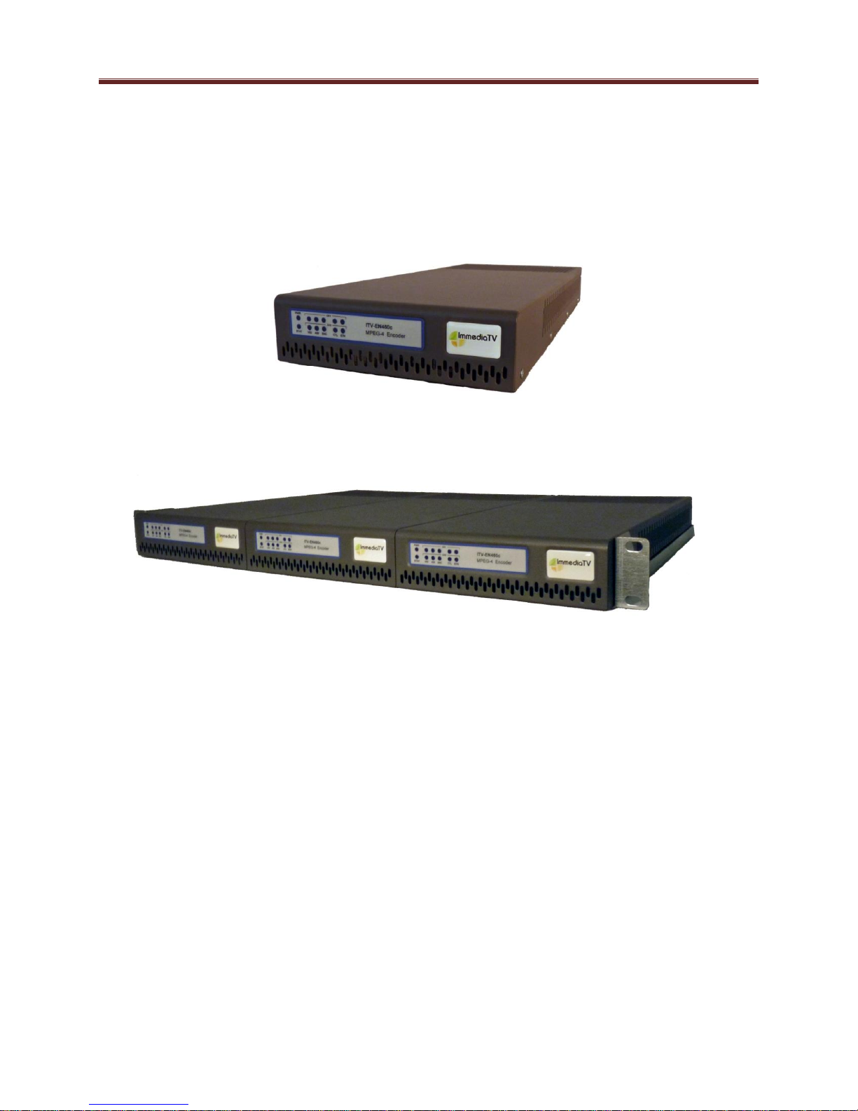
ITV-IP360c Indicators and Switches
The ITV-IP360c can be used as a desktop encoder, or in a 19” rack-mount tray that holds up to
three units:
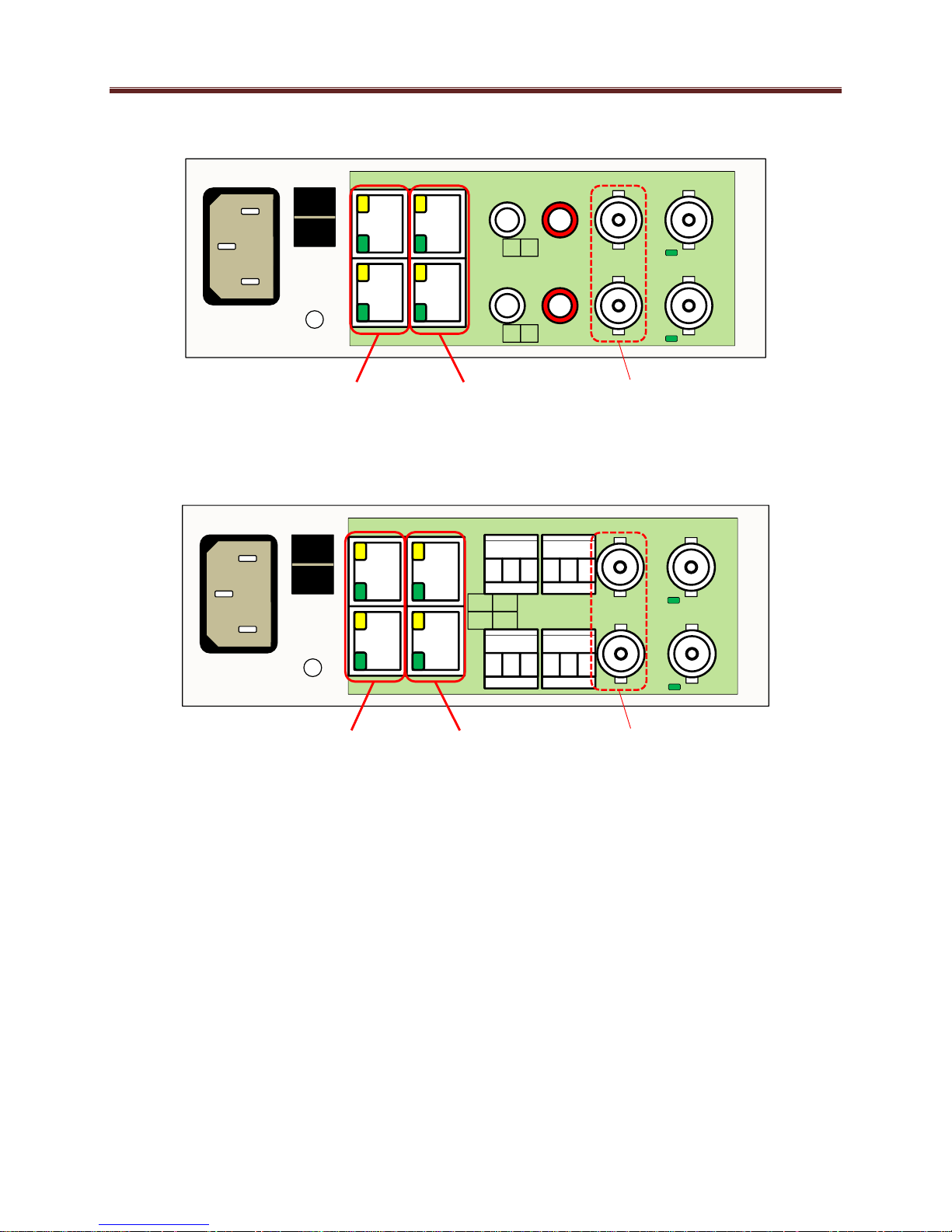
Back Panel
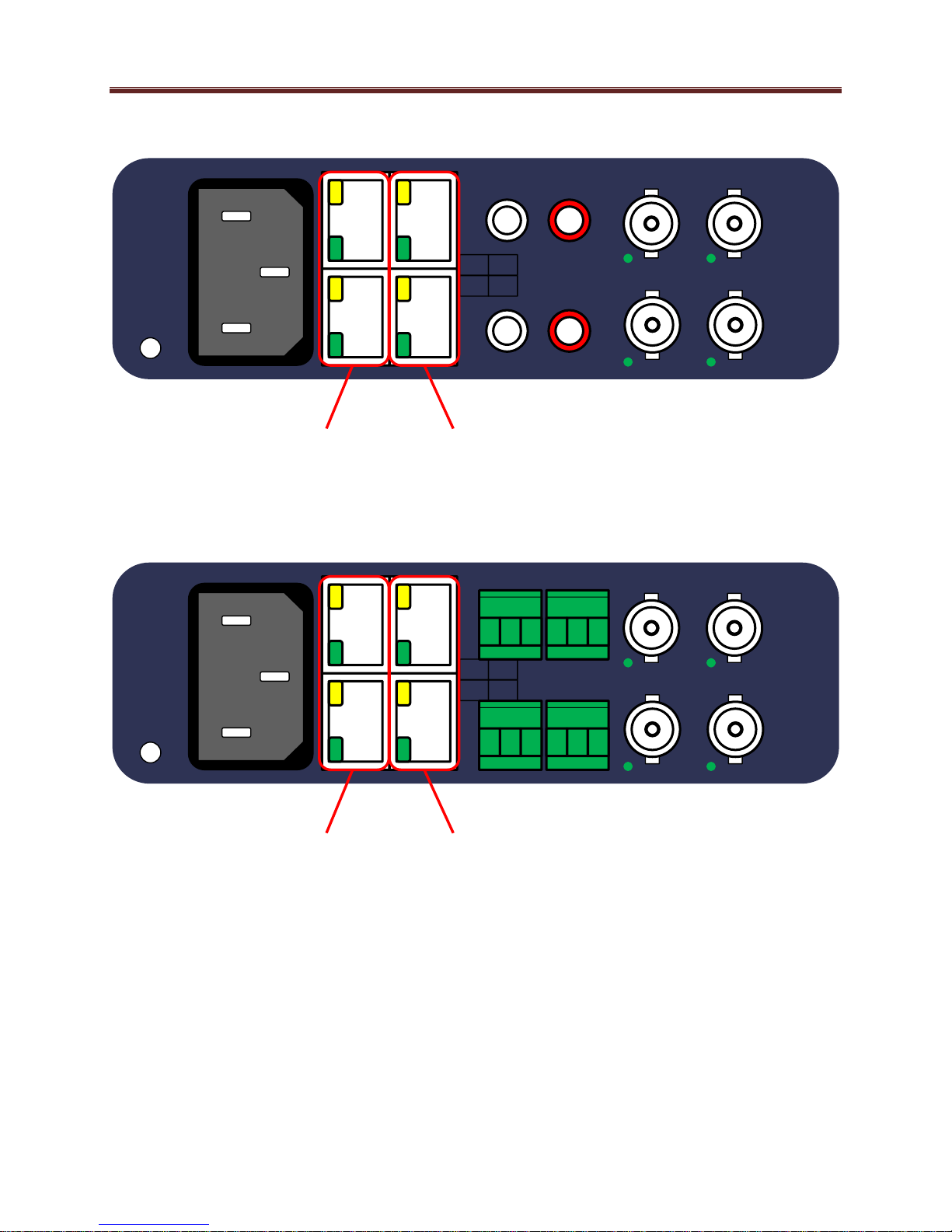
The ITV-IP360c ships with one of two possible back panels:
Unbalanced Audio Back Panel
Balanced Audio Back Panel
The panels are depicted in the next page.
Both panels include two software-configurable Composite/SDI video inputs on standard BNC
connectors, two streaming 100/1000 Mb/s Ethernet ports on standard RJ-45 connectors, and two
control 10/100/1000 Mb/s Ethernet ports on standard RJ-45 connectors, in addition to the analog
audio connectors. In the unbalanced version, the analog audio connectors are standard RCA
jacks; in the balanced audio version, the analog audio connectors are terminal blocks.
15
Unbalanced Audio Version
ETH1CTRL1
L AUD1 R VID1
ETH2CTRL2
L AUD2 R VID2
I
0
Streaming
Ethernets
Control
Ethernets
Unused
Ports
Balanced Audio Version
L AUD1 R VID1
ETH2CTRL2
L AUD2 R
VID2
I
0
ETH1CTRL1
+ - G + - G
+ - G + - G
Streaming
Ethernets
Control
Ethernets
Unused
Ports
Each of the video inputs has a green indicator LED, with the following states:
LED off: no video signal detected, or input not configured.
LED flashing: video input locked to the video signal.
o LED flashing about once per second: input video is SD.
o LED flashing about twice per second: input video is HD-SDI.
o LED flashing about 4 times per second: input video is 3G-SDI (1080p60).
Each of the Gigabit Ethernet ports has two indicator LEDs, with the following states:
Green LED:
o Off: No link
o On: Link
Yellow LED:
16
PWR
STAT
VID ENC CTL ETH
CH1
CH2
o Off: No activity (transmit and/or receive)
o Flashing: Port is currently transmitting and/or receiving
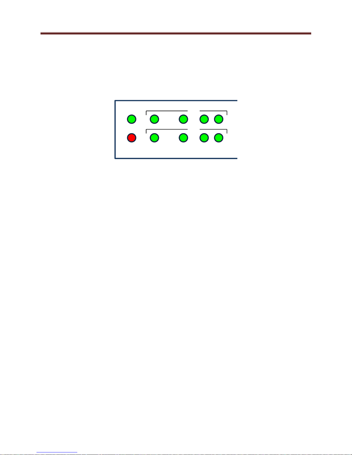
Front Panel Indicators
A similar set of indicators exist in the front panel of the unit. The layout is depicted below.
The front panel LED indicators are as follows:
STAT: indicates the overall status of the unit.
o Green: no active alarm
o Red: at least one critical alarm present
When powering up the unit, this LED will be red until the board starts operation. At that
point, it will turn green if there is no active alarm or stay red if there is at least one alarm.
PWR: indicates that the power is OK.
o Green: power OK
o Off: no power or insufficient voltage
CH1/CH2 VID: these behave exactly the same as the corresponding back panel video
input indicators.
CH1/CH2 ENC: these LEDs flash if the corresponding encoder is running, with output
available for routing to ASI, UDP or RTP. They will not flash if the encoder is stopped
(either by explicit configuration or by lack of input) or if it is in one of the Web streaming
modes (HTTP Live Streaming or Direct HTTP Streaming).
CH1/CH2 ETH and CTL: these indicate the status of the corresponding Ethernet
connection.
o Off: no link
o On: link OK, no activity
o Blinking: link OK, port is transmitting and/or receiving packets
Front Panel Default Switch
The front panel has a recessed switch that can be used to restore the unit to its defaults. Use a
pen or a small screwdriver to press this switch.
17

If the switch is pressed during normal operation, the control port IP address, mask and gateway
are restored to the following factory default settings:
IP Address: 192.168.1.30
Subnet Mask: 255.255.255.0
Gateway: 192.168.1.1
The STAT front panel indicator will change colors for about 3 seconds to acknowledge the
change. Note that this operation does not disturb the encoding function or the streaming
Ethernet ports (i.e., it is not service-affecting). The IP addresses of the streaming ports may be
also automatically changed if they are in the same subnet as the control IP address above.
If you press and hold this switch when the unit is powered off, and then power up the unit while
holding the switch, the following actions will be performed:
The control IP address, mask and gateway are reset to the factory defaults as described
above.
The unit configuration is cleared.
The unit reverts to the factory-installed firmware.
As before, the STAT LED will temporarily change color to acknowledge the command. When it
changes color, you can release the switch. You can use this feature in the unlikely event of a
corrupted firmware upgrade or a corrupted configuration.
18
ITV-IP360d Indicators and Switches
The ITV-IP360d can be used as a desktop encoder, or in a 19” rack-mount tray that holds up to
three units:
Back Panel
The ITV-IP360d ships with one of two possible back panels:
Unbalanced Audio Back Panel
Balanced Audio Back Panel
The panels are depicted in the next page.
Both panels include two software-configurable Composite/SDI video inputs on standard BNC
connectors, two ASI output ports on standard BNC connectors, two streaming 100/1000 Mb/s
Ethernet ports on standard RJ-45 connectors, and two control 10/100/1000 Mb/s Ethernet ports
on standard RJ-45 connectors, in addition to the analog audio connectors. In the unbalanced
version, the analog audio connectors are standard RCA jacks; in the balanced audio version, the
analog audio connectors are terminal blocks.
19
Unbalanced Audio Version
L AUD1 R ASI1 VID1
ETH2CTRL2
L AUD2 R
ASI2 VID2
ETH1CTRL1
Streaming
Ethernets
Control
Ethernets
Balanced Audio Version
L AUD1 R ASI1 VID1
ETH2CTRL2
L AUD2 R
ASI2 VID2
ETH1CTRL1
+ - G + - G
+ - G + - G
Streaming
Ethernets
Control
Ethernets
Each of the video inputs has a green indicator LED, with the following states:
LED off: no video signal detected, or input not configured.
LED flashing: video input locked to the video signal.
o LED flashing about once per second: input video is SD.
o LED flashing about twice per second: input video is HD-SDI.
o LED flashing about 4 times per second: input video is 3G-SDI (1080p60).
20

Presets
Config
Status
ITV-IP360d
Encoder
Control IP:
192.168.001.030
Each of the ASI output ports has a green indicator LED, with the following states:
LED off: ASI output port is disabled.
LED flashing: ASI output port is configured and enabled.
Each of the Gigabit Ethernet ports has two indicator LEDs, with the following states:
Green LED:
o Off: No link
o On: Link
Yellow LED:
o Off: No activity (transmit and/or receive)
o Flashing: Port is currently transmitting and/or receiving
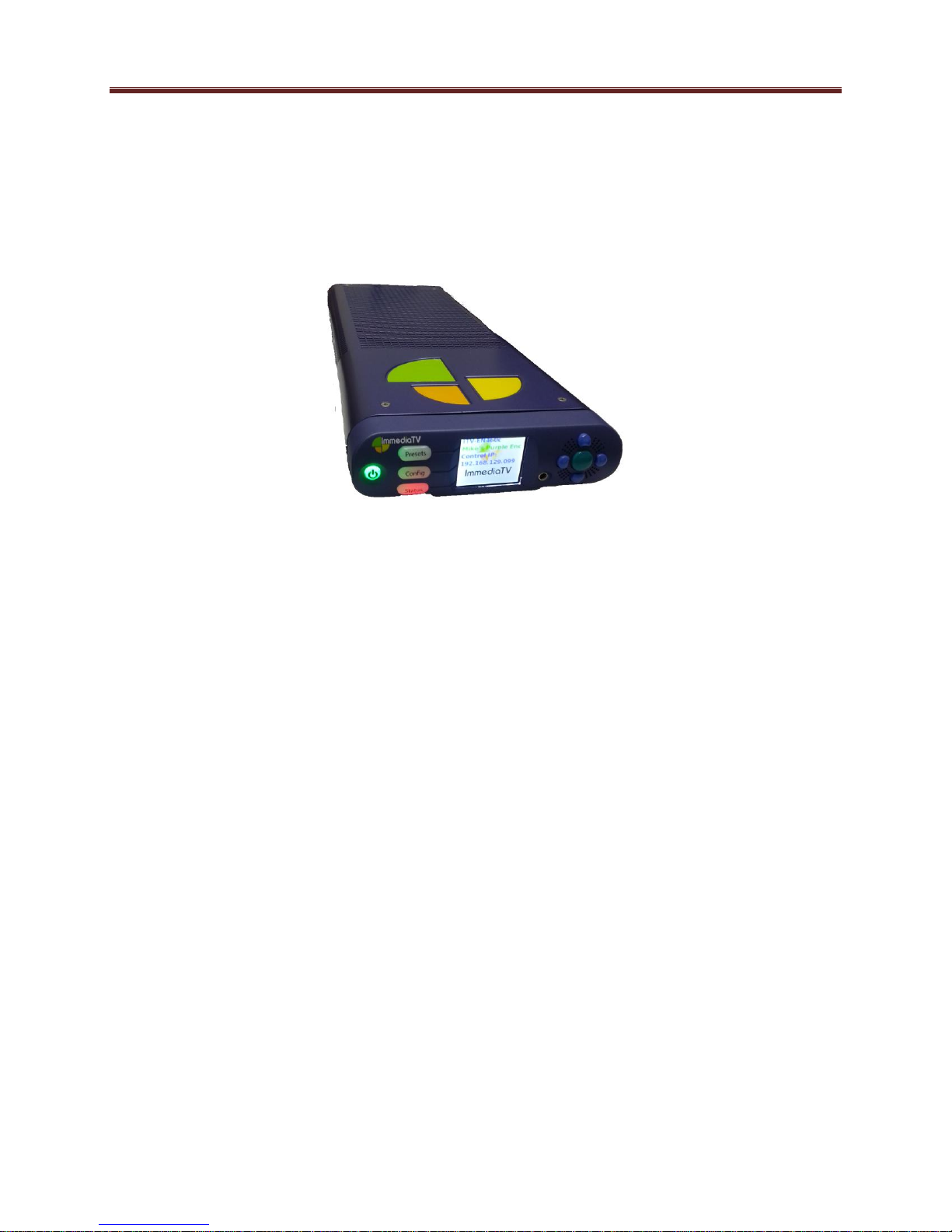
Front Panel Indicators
The ITV-IP360d has a front panel with an LCD display and buttons:
Operation of the panel is as follows:
The device powers up as soon as the power cable is connected to power. In order to turn
off the power, press and hold the power button on the left. The button will flash red for
about 3 seconds, and after that power turns off.
By default, the LCD screen shows the following information:
o Device Model: ITV-IP360d
o Device Name: User-assigned name, configured through DashBoard in the Control
Port Configuration Tab.
o Control Port IP Address: Current IP address assigned to the control port.
An example is depicted below:
21
ITV-IP360d
Encoder
Control IP:
192.168.001.030
Model
Device Name
Control Port IP Address
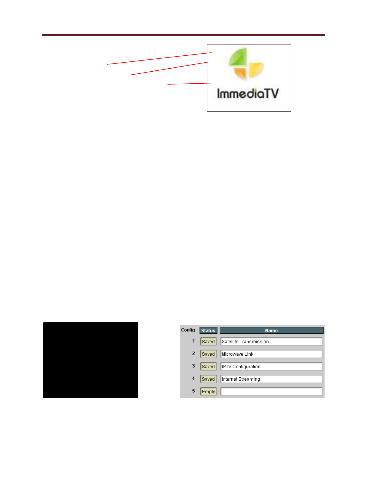
PRESETS:
>1: Satellite Transmis
2: Microwave Link
3: IPTV Configuration
4: Internet Streaming
5: (empty)
The LCD automatically turns off after 1 minute of inactivity. It turns back on as soon as
any key in the front panel is pressed.
Three function buttons to the left of the LCD screen, marked as Presets, Config and
Status. These buttons can light up either green or red. Their functions are:
o Presets button: brings up the 5 presets defined in the Error! Reference source
not found. tab in DashBoard and allows one of them to be selected and applied to
the device.
o Config button: allows for some more common items to be configured.
o Status button: allows for quickly inspecting the status and alarms in the device.
Navigation buttons to the right of the LCD screen. The center (green) button is the Enter
button, used to accept selections. There are 4 blue buttons to navigate menus (up, down,
left, right).
The Presets Menu
The ITV-IP360d has the ability to save up to 5 configurations (presets). The Presets front panel
key brings up a menu to select any of the presets. Use the Up/Down (blue) keys to select the
desired preset, and the Enter (green) key or the right (blue) key to select it. Use the left key to
exit the menu (or press one of the other function buttons).
The presets are defined in the Error! Reference source not found. tab in DashBoard.
Here is an example of the presets screen:
22
Encoder
Network
Clear Config
Reboot
Encoder 1
Encoder 2
Run/Stop
Video Rate
View Config
Change Config
Control Port
Ethernet 1
Ethernet 2
Encoder channel can be
started or stopped
Encoder bit rate can be
changed
Port IP address
configuration is displayed
Port IP address
configuration can be
changed
Clear the current unit
configuration (all
parameters back to
defaults)
Reboot the unit
Control Port
Ethernet 1
Ethernet 2
View Alarms
Network Status
Device Info
Control Ports
Stream Ports
Scroll through the active
alarms using the up/down
keys. Use the left/right
keys to read the complete
alarm text.
Reports link up/down,
interface speed and
duplex
Reports current software
revision, device serial
number, and hardware
version.
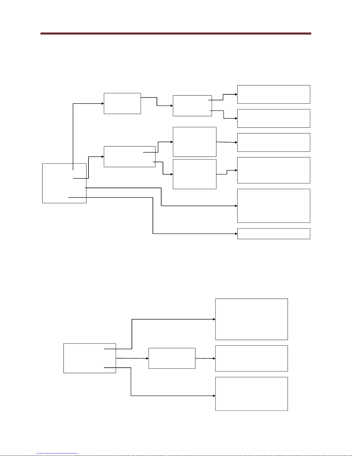
The Config Menu
The Config front panel key bring up the configuration menu tree. Only a few selected
parameters can be configured in this menu; these are the most common configuration parameters.
The Config menu tree is displayed below.
The Status Menu
The Status button will be lighted steady green if there are no active alarms, or flashing red if
there are active alarms. Pressing the Status button will bring up the status menu tree, depicted
below:
23

2
2
MVN-IP360/ITV-IP360c/d Operation and Management
The MVN-IP360/ITV-IP360c/d is configured using the free Dashboard™ application, which is
available for Windows, Apple OS X, and Linux. Dashboard can be downloaded from this link:
http://www.opengear.tv/dashboard-software
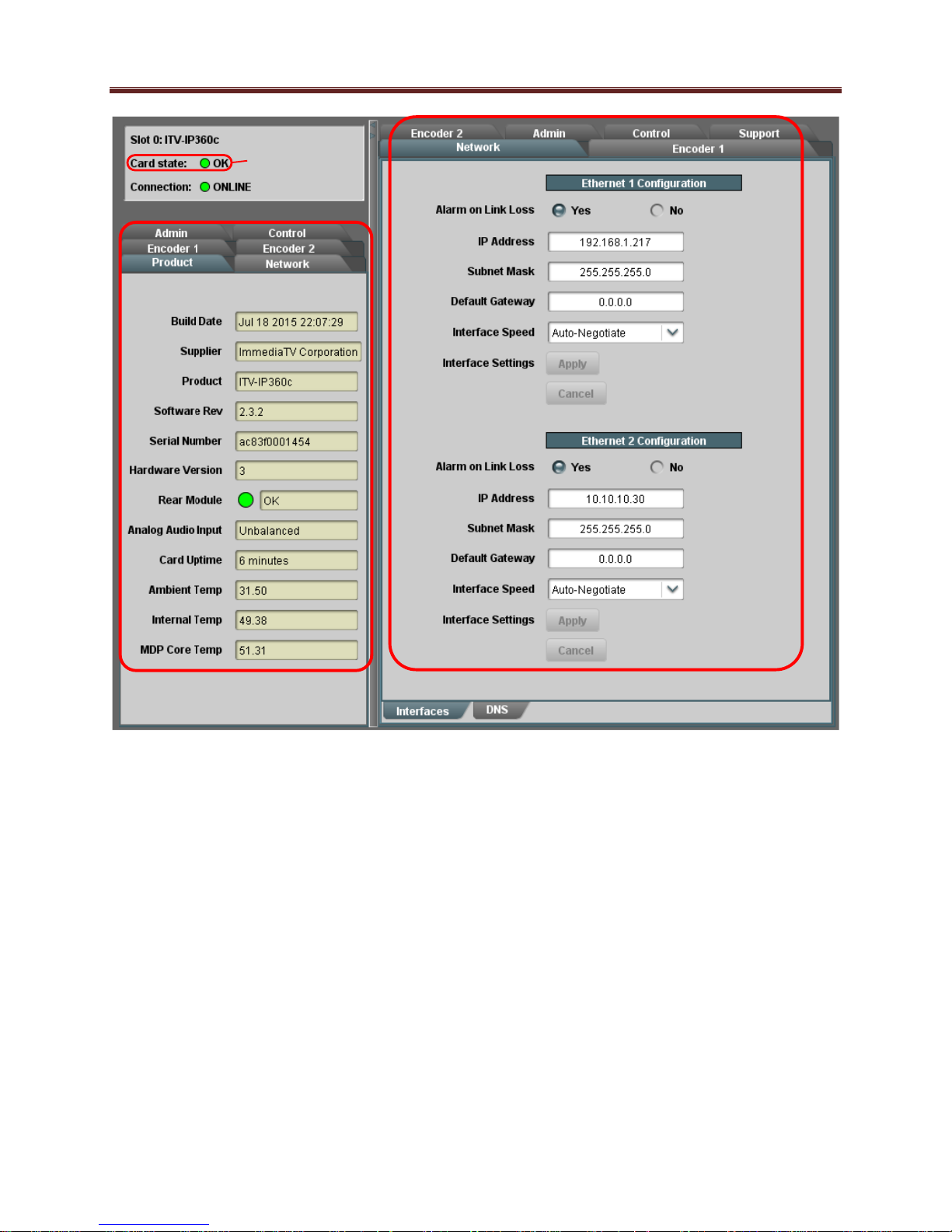
The MVN-IP360/ITV-IP360c/d user interface is depicted below. It is divided into a statistics
panel on the left, and a configuration panel on the right. Each panel has multiple tabs,
corresponding to the various functions in the unit. Note that the Card State alarm indicator is
also reflected in the green/red Status LED in the front of the board, or the Status button in the
ITV-IP360d. The Status LED will be green when Card State is green or yellow, and will be red
when Card State is red.
For the remainder of this manual, all described features are available for the MVN-IP360, the
ITV-IP360c and the ITV-IP360d, unless explicitly stated. The three products are referred to as
the IP360 encoder.
The following tabs are available:
Product: this tab provides general information on the unit, including firmware version,
uptime, temperatures, and other parameters. It appears only on the Statistics panel.
Network: this tab is used to configure the IP addresses and network information for the
Ethernet ports. The statistics side of the panel includes some additional information such
as link state.
Encoder 1, Encoder 2: these tabs are used to configure the two encoder channels.
Admin: this tab is used for general administrative functions, such as firmware upgrades,
licensing, logs, and configuration management. The Test Packet Generator configuration
is also found under this tab.
Control: this tab is available only in the ITV-IP360c/d. It is used to configure/monitor
the control ports and the SNMP functions of the device.
Please note that DashBoard versions 4.0 and 4.1 have GUI performance problems with the ITV-IP360c. We
recommend either version 3.0 or 5.0 or higher with the ITV-IP360c. Contact ImmediaTV if you need a copy of
DashBoard 3.0.
24
Statistics Panel Configuration Panel
Reflected in the
front Status
LED
25
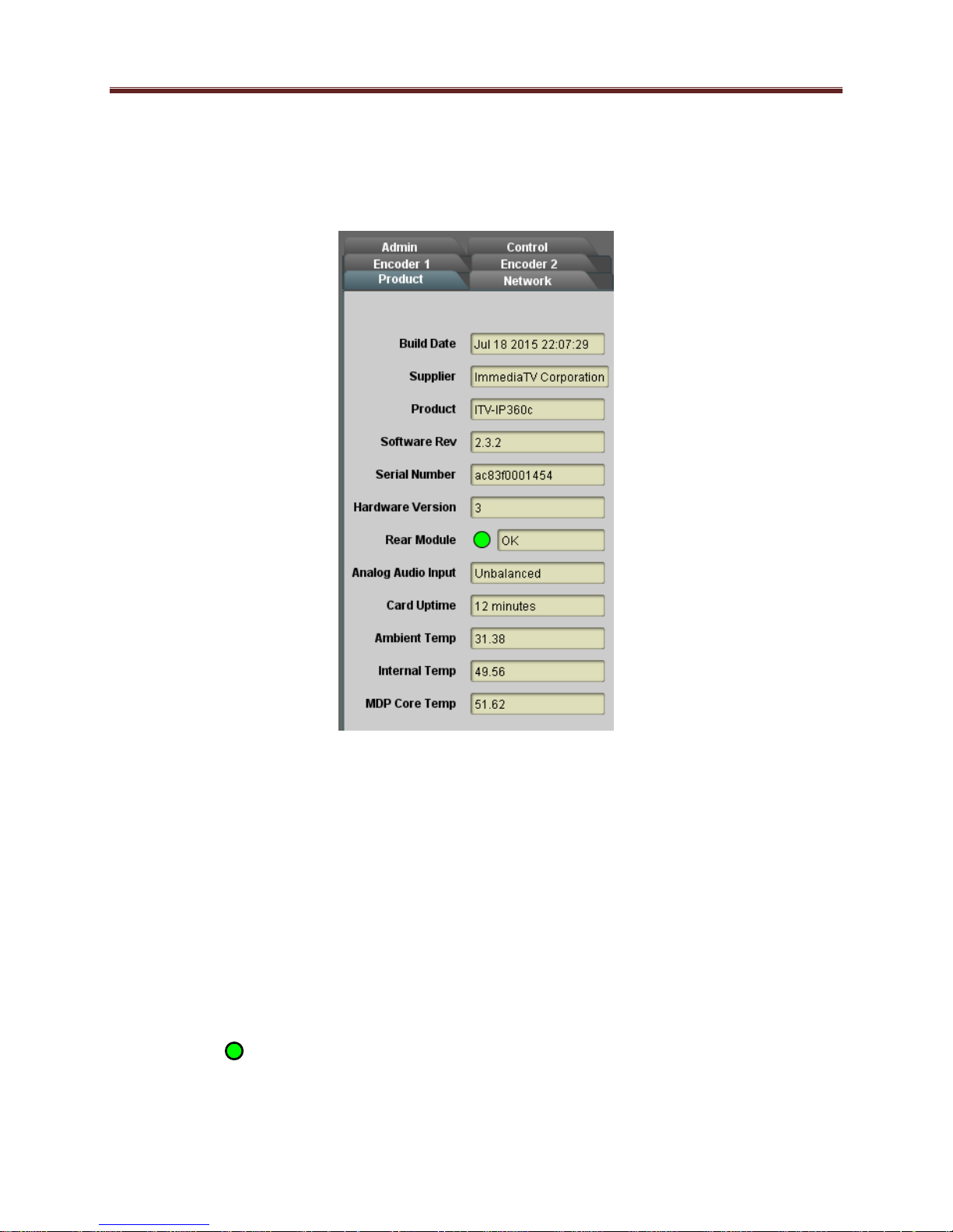
Product Tab
The Product Tab contains basic information about the IP360.
The following information is available:
Build Date: Date the firmware image was built.
Supplier: ImmediaTV Corporation.
Product: MVN-IP360, ITV-IP360c or ITV-IP360d.
Software revision: This indicates the firmware revision currently running. The format is
Major Version Minor Version Build Number.
Serial Number: This is the serial number of this particular IP360 unit.
Hardware Version: This indicates the board version number. Balanced audio support is
available for version 4 and later. All other functionality is the same across hardware
versions.
Rear Module: This indicates the status of the Rear I/O Module. It can have one of the
following states:
o OK: The Rear Module is the correct module for the MVN-IP360. In the
ITV-IP360c/d this indicator will be always green.
26
o Not Installed: The MVN-IP360 is not connected to a rear module. The card is
operating normally, but it will not be useful as there are no input and output
connections to it.
o Wrong Module: The MVN-IP360 is connected to a rear module that was not
designed for it (either from another openGear® vendor or for a different
ImmediaTV card). Depending on the signals present on that module, there may
be a small chance of damage to the MVN-IP360; ImmediaTV recommends that
this situation be rectified immediately. This alarm will cause the front status LED
to turn red. A card with hardware version 3 or lower will show this alarm for the
balanced audio rear I/O panel.
Analog Audio Input: This indicates the type of analog audio input (balanced or
unbalanced). This field will have an indication of unknown for
unrecognized/unsupported rear I/O panels.
Card Uptime: Indicates how long the unit has been running since it was last rebooted.
Ambient Temperature: Temperature, in degrees centigrade, of the air intake of the unit
(measured at the front edge of the unit).
Internal Temperature: Temperature, in degrees centigrade, at the back of the unit.
MDP Core Temperature: Temperature, in degrees centigrade, of the core MediaStorm
processing element.
The openGear® frame is designed to operate in environments with up to 40oC ambient. There is
typically a 5
measured by the MVN-IP360. If that measurement is at 45oC or higher, action must be taken to
cool down the ambient temperature.
The ITV-IP360c/d modular versions are designed to operate in environments with an ambient
temperature between 0 and 50 oC.
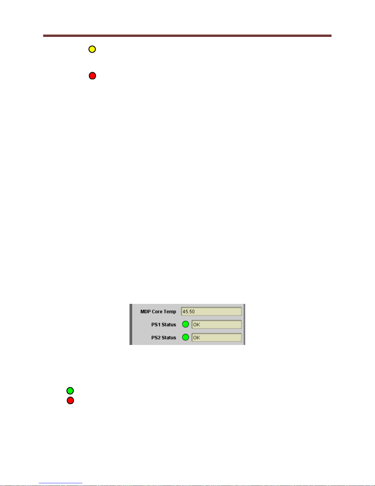
The ITV-IP360d includes two additional indicators in the Product tab:
o
C temperature raise from the external ambient to the “Ambient Temperature”
The ITV-EN460d has two internal redundant power supplies. Each power supply is capable of
individually powering up the device. The PS1 Status and PS2 Status indicate the status of each
of the internal power supplies, as follows:
OK: The power supply is working normally.
No Power: The power supply has failed and is not providing power. Contact
ImmediaTV to get the unit repaired.
27
Configuration Tabs
Network Tab
The Network Tab allows for configuration/monitoring of the two streaming Ethernet ports, and
optional configuration of DNS servers.
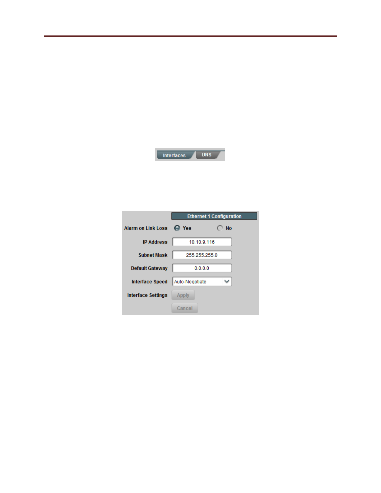
Network Configuration Tab
The Network Configuration Tab is further divided into the following tabs:
The Interfaces tab is used to set the individual parameters for each of the streaming
Ethernet ports.
The DNS tab is used to optionally configure DNS servers.
Network Configuration Interfaces Tab
This tab allows the configuration of the individual streaming ports.
The following parameters can be configured:
Alarm on Link Loss: If set to Yes, the unit will raise an alarm if this Ethernet interface
loses link. The Card State indicator in Dashboard™ and the front Status LED will both
be red. If set to No, the unit will still report loss of link in the Statistics page but no alarm
will be raised. ImmediaTV recommends turning on the alarm for ports that are in use;
only turn it off if you do not plan to connect that port to a network.
IP Address: Enter the desired IP address for this Ethernet port. In the ITV-IP360c, this
IP address cannot be the same as the Control Port IP Address (see the Control Port
Configuration Tab).
Subnet Mask: Enter the desired subnet mask for this Ethernet port.
Default Gateway: Enter the desired default gateway for this Ethernet port, or 0.0.0.0 if
no gateway is available.
28
 Loading...