

Page 1

I:\publik\TECH_MAN\TRIME-GW\english\GW-MAN_e-Temperatur_Vers2_6.doc
Page 2

Thank y
ou for buying IMKO.
Should you have any queries, please
don’t hesitate to contact your local
distributor or contact IMKO direct:
IMKO Micromodultechnik GmbH
Im Stoeck 2
D-76275 Ettlingen
Germany
Phone: +49-7243-5921-0
Fax: +49-7243-90856
e-mail: info@imko.de
internet: http://www.imko.de
Operating instructions for TRIME
status November 2008
List of contents
®
-GW
1 Instrument description ...............................................................................................................................4
1.1 The method of measurement....................................................................................................................4
1.1.1 TRIME - The patented TDR method.................................................................................................4
1.1.2 TRIME compared to other methods..................................................................................................4
1.2 The operating principle .............................................................................................................................4
1.2.1 Measuring with floating mean-value..................................................................................................4
1.2.2 Temperature compensation..............................................................................................................4
1.2.3 The analogue output.........................................................................................................................5
1.2.4 Error display and error messages.....................................................................................................5
1.3 Configuration ............................................................................................................................................6
1.3.1 Product selection switch ...................................................................................................................6
1.3.2 Offset-correction...............................................................................................................................6
1.3.3 Averaging time..................................................................................................................................7
1.3.4 Calibration and temperature compensation exchange......................................................................8
1.4 Instrumentation.........................................................................................................................................9
1.5 Connections............................................................................................................................................10
1.5.1 Connector for strip terminals...........................................................................................................10
1.5.2 The probe connector (Probe)..........................................................................................................10
1.5.3 The configuration connector (Configuration)...................................................................................10
1.5.4 The RS232 connector (RS-232) .....................................................................................................10
1.5.5 The IMP-Bus connector (IMP-Bus).................................................................................................10
1.6 Connections TRIME®-GW ......................................................................................................................11
1.7 The probe...............................................................................................................................................12
1.7.1 The rod probe GR...........................................................................................................................12
1.7.2 The surface probe GS1 ..................................................................................................................12
2 Installation .................................................................................................................................................13
2.1 Probe installation....................................................................................................................................13
2.2 Instrument installation.............................................................................................................................14
2.3 Wiring .....................................................................................................................................................15
_____________________________________________________________________________
2
Page 3

2.3.1.1
Integration into the existing system-electronics................................................................ 15
3 Initial operation and handling ..................................................................................................................17
3.1 Adjustment guidelines.............................................................................................................................17
3.2 Adjustments for initial operation..............................................................................................................17
3.2.1 Adjustment for plants with several TRIME®-GW.............................................................................17
3.2.2 The product selector-switch............................................................................................................18
3.2.3 Selection and application of the reference method.........................................................................18
3.2.4 Initial operation................................................................................................................................18
3.2.5 Recording measurement data in trial operation ..............................................................................19
3.2.6 Setting the product selector-switch (adjustment) ............................................................................19
3.2.7 An example.....................................................................................................................................20
3.3 Practical application................................................................................................................................21
3.3.1 Monitoring during grain delivery......................................................................................................22
3.3.2 Manual control of the grain dryer ....................................................................................................22
3.3.3 Automatic control of the grain dryer................................................................................................22
4 Special functions.......................................................................................................................................23
4.1 Operating the TRIME®-GW measurement systems in an intermittent flow of material............................23
4.1.1 Behaviour upon detection of air around the probe rods ..................................................................23
4.1.2 Control via the internal time constants Queue-FillingTime and Queue-DischargeTime..................23
4.1.3 A side-effect when using the time constants Queue-FillingTime and Queue-DischargeTime.........24
4.1.4 Setting Queue-FillingTime ..............................................................................................................24
4.1.5 Control via an external, digital input signal HaltM ...........................................................................25
4.1.6 Electrical specification of the input signal HaltM / HaltM-In.............................................................25
4.2 Basis calibration after replacing system components .............................................................................26
4.2.1 General notes regarding basis calibration.......................................................................................26
4.2.2 Reference values of the calibration media used for the basis calibration........................................26
4.2.3 Preparatory measures ....................................................................................................................26
4.2.4 The procedure using the configuration plug “TRIME®-GW basis calibration”..................................26
5 Technical data ...........................................................................................................................................28
6 TRIME-GW adjustment protocol ..............................................................................................................30
_____________________________________________________________________________
3
Page 4

1 Instrument description
1.1 The method of measurement
1.1.1 TRIME - The patented TDR method
The TDR method (Time-Domain-Reflectometry) is based on a dielectric measurement method in
which the transit times of electromagnetic pulses are determined in order to measure the dielectric constant or the water content.
TRIME systems comprise a probe with parallel metallic rods that are inserted into the flow of grain
and a die-cast aluminium case with an integrated TDR measuring transformer. A high-frequency
TDR- pulse (1 GHz) generated in the instrument propagates along the wave guides inducing an
electromagnetic field around these guides and thus in the material around the probe. Using a
patented method, IMKO has succeeded in measuring the transit time of with a resolution of 10
seconds.
The determined moisture content can either be transmitted via an analogue output (0 or 4...20
mA) to a display in the process control room or fed directly into an automatic process control system. In addition, the TRIME systems can be easily networked and extended via a serial bus interface (RS232/V24).
-12
1.1.2 TRIME compared to other methods
In contrast to capacitive, infra-red- or resistance methods of measurement, the TRIME TDRtechnology shows greater indifference to the grain type, the temperature of the product and the
ionic conductivity. The remaining temperature dependency is compensated by means of a grain
temperature measurement in the probe.
3
The TRIME method fully penetrates a corn volume of 1..2 dm
about the moisture close to the surface (such as with the infra-red method) but also the water
content of the unground, whole corn. Complex and fault-prone bypass constructions, as required
by the disproportionately expensive microwave method or transmissive infra-red method, can be
dispensed with when using TRIME systems. The modular technology allows later system extensions with minimal expense. TRIME technology is also highly flexible in terms of probe design
thus making it adaptable to numerous applications.
. You thus not only obtain data
1.2 The operating principle
1.2.1 Measuring with floating mean-value
TRIME-GW constantly takes readings in cycles of 0.5 s and passes them on via the analogue
output. However, not the individual values just recorded are directly output, but the mean value of
a certain number of measurements thereby filtering out any temporary fluctuations that may occur. These fluctuations can be caused by an uneven distribution of moisture in the flowing grain.
The number of readings from which a final measurement is to be taken, or the averaging time,
can be set depending on the particular application (see page 6).
1.2.2 Temperature compensation
A built-in temperature sensor measures the grain temperature. Thus the measured water content
value is automatically corrected dependent on the grain temperature and the water content. It is
very important that the probe is in the colder exhaust air area of the dryer. It would measure the
air temperature instead of the grain temperature, it was in the heated inlet air zone.
_____________________________________________________________________________
4
Page 5

1.2.3 The analogue output
The measured value is conveyed via the analogue output in the form of electrical current. Two
versions of the instrument are available, 0..20 mA and 4..20 mA. The relationship between the
c
urrent,
I, at the analogue output and the grain moisture, (in %), arises from the following for-
mula:
0..20 mA: Fehler! Textmarke nicht definiert.
4..20 mA: Fehler! Textmarke nicht definiert.
I 5000 Example: 1 mA = 5%
I 6250 25 Example: 8 mA = 25%
The display units, available as optional extras, present the moisture readings directly as a percentage. The analogue port can also be used for connecting a line printer or a controller for regulating the dryer.
1.2.4 Error display and error messages
Errors occurring while measurements are being taken are displayed at the analogue output as
currents greater than 20 mA (see the table below). TRIME-GW, however, is very tolerant of errors. Malfunctions that occur during measurement don not appear at the analogue output until
25% of the readings are show discrepancies. If no more incorrect measurements occur, at least
80% of the values must be free of errors for a valid reading to appear at the analogue output. This
tolerance of errors allows trouble-free operation even when temporary faults occur, which is of
particular significance when used on controllers.
The only "error" that is permitted to appear in operation is error no. 66. It appears when the probe
is not immersed in grain.
The display instruments show occurring faults as "EE.E" or as values above 100% on the display
panel, dependent on the display type. When a line printer is connected, the fault is indicated by a
line at the upper limit or above 100%. To distinguish the type of fault the display instrument or the
line printer must be able to show values above 20 mA.
The following table shows the meanings of the individual faults and the corresponding currents.
Table 1
Fault
no.
30 26.0 mA 24.80 mA 130%
31 26.2 mA 24.96 mA 131%
Current
0..20 mA
Current
4..20 mA
Displayed
value
Possible cause
Coaxial cable missing or TDR-electronics defect
TDR-measurement incorrect (only in extremely saline
media)
33 26.6 mA 25.28 mA 133%
34 26.8 mA 25.44 mA 134%
35 27.0 mA 25.60 mA 135%
62 32.4 mA 29.92 mA 162%
Salinity too high
Data implausible or EEPROM defective
Power supply too low
Temperature sensor in the probe: temperature readings
implausible. Sensor faulty or detached from probe; EMC/
process faults; extremely rapid temp. fluctuations
63 32.6 mA 30.08 mA 163%
Temperature sensor in the probe: sensor not recognised
Sensor faulty; wiring broken; short circuit; switch on without probe
64 32.8 mA 30.24 mA 164%
Temperature sensor in the probe: communication problems
Sensor faulty; loose connection; EMC faults
66 33.2 mA 30.56 mA 166%
Probe not fully immersed in grain
_____________________________________________________________________________
5
Page 6
1.3 Configuration
The instrument configuration is set optimally at the factory prior to delivery of the TRIME-GW. In
some cases, further optimisation of these instrument-internal settings may be necessary.
The following TRIME-GW settings can be altered:
Product selection switch (0..F initially use switch setting 8)
Offset correction (shifting the measurements)
Averaging time (reaction speed of the readings)
Calibration and temperature compensation (when using a variety of materials)
Behaviour during filling/discharge, i.e. where material being measured is not always present
(e.g. in the discharge chute)
These functions are described in detail in Section 4.1 Operating the TRIME®-GW measure-
ent systems in an intermittent flow of material on page 23
m
Each of these settings remains unaltered even after the instrument is turned off, i.e. permanent
storage.
1.3.1 Product selection switch
After you wired up the system as described initially start with the switch setting 8, after the system
is running take samples close to the probe and compare the value of the TRIME-GW with the
result of your reference instrument.
Example:
The TRIME-GW shows an value of 18,0% the reference instrument shows an value of 15,0% so
you have to change the switch setting from initial setting 8 to the new switch setting B
The here shown values are for the use with the standard calibration set for the measurement in
grain (for use with maize, wheat, rye and barley), for other materials these values are specific:
Table 2
Switch position Switch (Offset
to raw value)
0 + 3 % Inactive (for testing)
1 +10 % Active
2 + 9 % Active
3 + 8 % Active
4 + 7 % Active
5 + 6 % Active
6 + 5 % Active
7 + 4 % Active
8 + 3 % Active
9 + 2 % Active
A + 1 % Active
B ± 0 % Active
C - 1 % Active
D - 2 % Active
E - 3 % Active
F - 4 % Active
Temperature compensation:
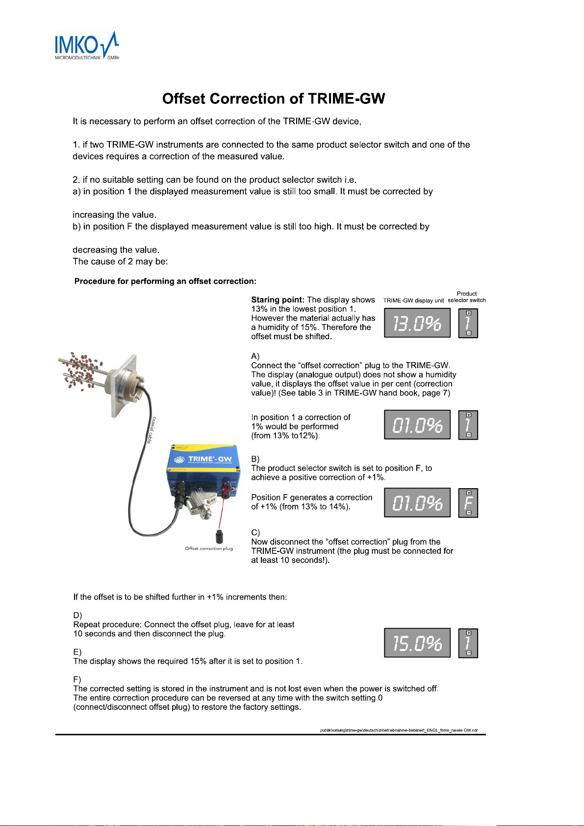
1.3.2 Offset-correction
The measurements taken by the TRIME-GW may vary slightly depending on the location of the
probe in the dryer because metallic components or hollow spaces (e.g. the dryer walls or baffle
structures inside the dryer) in the immediate vicinity of the probe may affect measurement. In
order to correct these installation-related but constant and reproducible errors, a so-called "offset-
_____________________________________________________________________________
6
Page 7

correction value" can be deposited in the TRIME-GW. This value is automatically added to every
measurement.
The offset-correction should only be done if the desired value can not be reached by using the
product selector switch!
The offset-correction value can be altered as follows by inserting the "TRIME-GW offsetcorrection" plug:
1.
Insert the plug into the TRIME-GW's configuration socket. The offset-correction value can now
be selected at the product selector-switch according to the following table. The selected value
is presented at the analogue output (or on the LED display in the measuring station). Each position of the product selector-switch corresponds to a particular offset-correction value.
Table 3
Switch position Offset-correction value
0 Restore to factory setting
1 -1.0 %
2 -0.8 %
3 -0.6 %
4 -0.4 %
5 -0.3 %
6 -0.2 %
7 -0.1 %
8 0.0 %
9 +0.1 %
A +0.2 %
B +0.3 %
C +0.4 %
D +0.6 %
E +0.8 %
F +1.0 %
2. As soon as the plug is removed, the value currently set at the product selector-switch is adopted. If the plug is removed when the switch is on 0 the offset-correction value is erased and the
factory setting restored.
3. After changing the offset value reset the setting of the product selection switch back to the
initial setting before aligning the Offset!!!
If it is necessary to enter correction values greater than 1% or intermediate values not shown in
the table, the process can be repeated a number of times. A shifting of 0.5% can, for example, be
achieved by 0.2% + 0.3%.
1.3.3 Averaging time
The TRIME-GW detects a new reading every half-second and, at the same intervals and via the
analogue port, outputs the appropriate mean value of the readings spanning a predetermined
period. The averaging time, therefore, is the equivalent of the TRIME-GW's "memory". The longer
the selected period, the more sluggish the reaction time when grain of varying degrees of moisture flows past the probe. A long averaging time thereby leads to a more stable reading as well.
This is of particular importance when operating the TRIME-GW in dryers so that fluctuations in
readings caused by the varying moisture in grain layers can be compensated for.
The factory setting of the averaging time is 3 minutes. This is a proven setting for grain dryers. If a
faster reaction in your application is necessary a lower value should be selected. Scattering of the
displayed moisture value can be prevented by a higher averaging value.
The averaging time can be changed as follows by connecting the "TRIME-GW averaging time"
plug:
Insert the plug into the TRIME-GW's configuration socket. As soon as the plug is connected,
1.
the prevailing measurement appearing at the analogue output (or on the LED display in the
_____________________________________________________________________________
7
Page 8

measuring station) is replaced by the currently set averaging time as per the following table.
Each position of the product selection switch corresponds to a particular averaging time. If the
configuration plug is now removed again, no alteration will be made to the averaging time
stored in the instrument.
Table 2
Switch position Averaging time Field of application
0 previous setting remains unchanged
1 0.1 min = 0.5 s
2 0.1 min = 6 s Moisture measurement upon delivery
3 0.2 min = 12 s
4 0.3 min = 18 s
5 0.4 min = 24 s
6 0.6 min = 36 s
7 0.8 min = 42 s
8 1.0 min Moisture measurement in the dryer
9 1.2 min or in the grain silo
A 1.5 min
B 2.0 min
C 3.0 min (Factory setting)
D 5.0 min
E 10.0 min
F 20.0 min
2. As soon as the product selector-switch is changed for the first time, the corresponding averaging time can be read from the display.
3. As soon as the plug is removed, the value currently set at the product selection is adopted by
the instrument. If the plug is removed when the switch is on 0, the internal setting remains unaltered.
1.3.4 Calibration and temperature compensation exchange
The calibration for all 15 positions of the product selector-switch can also be replaced. This is,
however, only necessary for special materials. It can be done simply by inserting the appropriate
calibration plug. The plug must only remain connected for 10 to 15 seconds. The instrument extracts the data from the plug and transfers them to its internal memory.
The temperature compensation can also be changed or even deactivated by an appropriate calibration switch. If the probe must necessarily be installed in the heated inlet air zone a deactivation
of the temperature compensation can be necessary.
The calibration plugs are available as accessories. Alternatively, calibrations and temperature
compensation can be exchanged by a Windows95/98 software.
_____________________________________________________________________________
8
Page 9
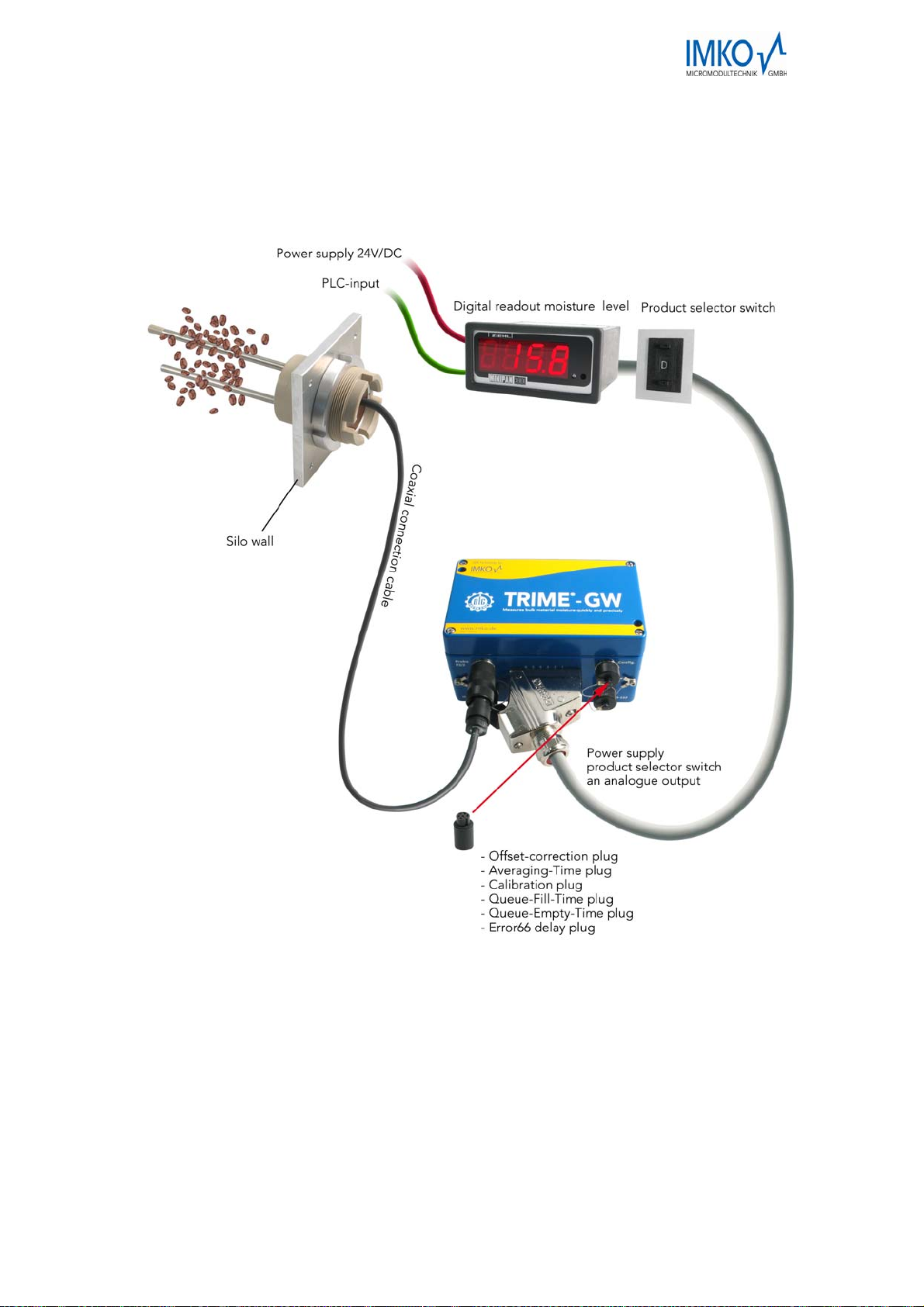
1.4 Instrumentation
Figure 1: The TRIME®-GW components
®
The TRIME
-GW system comprises the actual measurement transformer in a aluminium die-cast
casing and the measuring probe that is connected to a coaxial cable over 2.5 m long. A display
unit that can include the product selector-switch is connected to present the readings.
Also available as an optional extra is the connection to a controller, a PLC, a PC or a line printer.
_____________________________________________________________________________
9
Page 10

1.5 Connections
1.5.1 Connector for strip terminals
The 12-pin connector (male) allow connection of the screw connector block to an SPS via the 12pin connector (female) and ensure the protection level IP65 (dustproof, splash-proof) once installed. A detailed pin assignment you’ll find on page Fehler! Textmarke nicht definiert.Fehler!
Verweisquelle konnte nicht gefunden werden..
Table 4
Contact Term Explanation
1 +Vs Positive pole for the power supply
2 R/T IMP-bus signal, for PC communication
3 0V Negative pole for the power supply
4 COM IMP-bus signal, for PC communication
5 SW Switch output for the product selector-switch
6 S0 Switch input for the product selector-switch (Binary digit 20, least significant bit)
7 S1 Switch input for the product selector-switch (Binary digit 21)
8 S2 Switch input for the product selector-switch (Binary digit 22)
9 S3 Switch input for the product selector-switch (Binary digit 23, most significant bit)
10 Ana GW + Positive pole analogue output, 0(4) .. 20mA
11 Ana GW - Negative pole analogue output, 0(4) .. 20mA
12 Halt M Input signal to stop the measurement
1.5.2 The probe connector (Probe)
A dust- and splashproof Binder-connector for connecting the coaxial cable to the measuring probe. Only the probe calibrated for this instrument can be connected. The number in the ca-
ble support sleeve must correspond to the serial number printed on the instrument. Probes and cables from different instruments are not to be interchanged.
1.5.3 The configuration connector (Configuration)
With the help of this connector, the application parameters of the instrument can be changed
without having to connect a PC (see page 6).
1.5.4 The RS232 connector (RS-232)
A PC can be hooked up to this connection via an RS232 cable (IMKO accessory) for configuration-, calibration and diagnosis purposes.
1.5.5 The IMP-Bus connector (IMP-Bus)
Electrical connection via Central Module SM-23U.
_____________________________________________________________________________
10
Page 11

1.6 Connections TRIME®-GW
Probe connector
Configuration
connector
Grounding
IMP-Bus connector
Pin 1
+Vs
2 R/T
3 0V
4 COM
RS232 connector
Pin 1 N.C.
2 TxD
3 RS GND
4 RxD
12-pin connector (male)
see detailed pin assign-
ment on page 16.
_____________________________________________________________________________
11
Page 12

1.7 The probe
1.7.1 The rod probe GR
The GR probe comprises a cylindrical probe-head made of a heat-resistant special-purpose plastic that has a threaded bore for mounting on silo- or housing walls. The actual measuring probe
consists of two parallel, steel prongs that are set into this probe head. The area relevant for moisture measurement surrounds the prongs.
Figure 2: TRIME®-GR
1.7.2 The surface probe GS1
The GS probe has been specially designed for use in areas where probe prongs cannot be inserted into the produce to be measured. The measuring electrodes in this probe are sunk into a
rectangular plastic panel. This enables it to be fitted in such a way that it practically becomes a
single entity with the vessel walls, without any protruding elements.
Figure 3: TRIME®-GS1
Probes and cables from different instruments are not to be interchanged as this may otherwise lead to discrepancies and deviations in measurements. Please note the serial number labels!
_____________________________________________________________________________
12
Page 13

v
2 Installation
The conditions for installation depend heavily on the characteristics of the plant. The optimum
location must be sought for each case individually. The following guidelines will be of assistance.
2.1 Probe installation
The probe must be fitted in such a way that the prongs protrude into the interior of the dryer or
silo. Reliable measurements can only be ensured when the prongs are fully immersed in grain.
Therefore, a location for installation must be chosen where ...
the full length of the prongs is covered by and in contact with grain.
hollow spaces cannot occur in the direct vicinity of the probe prongs (at least 5 cm from the
prongs).
the prongs are in the stream of exhaust (outlet) air. The temperature compensation fails in the
inlet (heated) air zone.
metallic objects, e.g. channelling panels in dryers, are at least 5 cm from the prongs. Meas-
urement anomalies caused by metallic objects can be eliminated by offset-correction (see
page Fehler! Textmarke nicht definiert.).
no temperatures above 120°C occur.
In continuous-flow dryers, the best place for optimum regulation is at the end of the drying
zone. Regulation can, of course, be further improved by installing additional probes in the drying
zone and at the end of the cooling zone. The final moisture content at the end of the drying process can be best monitored when a probe is fitted at the discharge point as well.
Exhaust
roof
s
u
r
a
e
m
grain flow
e
m
m
e
a
s
u
r
e
e
n
t
f
i
e
l
d
TRIME-GR
m
e
n
t
f
l
d
i
e
grain flow
entilation
roof
Figure 4: A schematic diagram of a roof-dryer (exhaust side !) with a fitted probe. The elliptical area
represents the measuring range of the TRIME
ishes the greater the distance from the probe.
Nevertheless, the measurement range can extend into the area of the ventilation roofs where
there is no grain. This means that the reading includes a proportion of air in the measurement
volume and thus the resultant relative water content is too low. This constant, location-specific
offset can be compensated for by offset-correction (see section Fehler! Verweisquelle konnte
nicht gefunden werden.).
®
-GW probe. The field of measurement dimin-
_____________________________________________________________________________
13
Page 14

In the c
veying speed is lowest. We recommend installation in the reservoir or close to the discharge
point.
Probe installation can be carried out in the following steps:
1. Drill a 72 mm – diameter hole in the container wall or cut out a square hole using an angle-
2. Secure the aluminium flange to the wall with four M5 screws (Cut M5 threads into the wall).
3. Screw the probe into the flange as far as possible.
4. Use the locknut to secure the probe in such a way that the prongs are set slight past vertical
ase of rotary dryers and delivery points, the probe should be fitted where the grain con-
grinder.
(10° to 15°).
Important: Under no circumstances is the probe to be connected to
the instrument while being installed as the electronics may
be destroyed otherwise!
2.2 Instrument installation
The TRIME®-GW must be installed in the vicinity of the probe as the length of the probe cable is
only 2.5 m for technical reasons. The temperature of the surroundings should, however, not exceed 60°C (ideal: outgoing-air end, external wall of dryer). The instrument can be mounted at a
suitable point with screws through the two diagonally-opposed holes in the casing. An aluminium
mounting-plate is available as an optional extra.
If the instrument is to be mounted on a surface whose temperature exceeds 60°C, it must be fitted using spacing bolts (min. 8 mm) to prevent the direct transfer of heat from the wall to the instrument casing.
The instrument should not permanently be exposed to direct precipitation, although it is specified
to IP65. For outdoor usage it should be mounted below a protection roof, e. g. a horizontal mounted plate.
Distance 8 mm
_____________________________________________________________________________
14
Page 15

2.3 Wiring
First of all, connect the probe to the instrument using the black coaxial connection lead. When
doing so, make sure that the serial numbers on the probe, the cable and the instrument are identical to each other to ensure reliable readings.
As shown in Figure 1 (Page 8), power is supplied via the screw connector block, the product selector-switch connected and the measurement extracted via the analogue output (0(4)..20mA).
The illustration shows how two instruments are connected in cascade. This method significantly
reduces the amount of wiring required if several (up to four) instruments are to be connected.
The two connection ports R/T and COM should also be wired up this point even if no computer
link is planned for the time being. Measurement extraction by PC or connection of a PC for the
purposes of diagnosis can be realised, later on too, by connecting a conversion module SM-23U.
2.3.1.1 Integration into the existing system-electronics
Instead of implementing the TRIME®-GW independently for monitoring purposes, it can also be
integrated into existing systems. For example, a programmable logical controller (PLC) can extract the readings from the current output 0(4)..20mA. The function of the product selector-switch
can also be taken over by another electronic system (e.g. PLC) that has relay outputs. Relay contacts between the connection SW and the inputs S0 to S3 allow product selection as per the following table:
Table 5
Product selection SW – S3 SW – S2 SW – S1 SW – S0
0 open open open open
1 open open open closed
2 open open closed open
3 open open closed closed
4 open closed open open
5 open closed open closed
6 open closed closed open
7 open closed closed closed
8 closed open open open
9 closed open open closed
A closed open closed open
_____________________________________________________________________________
15
Page 16

B closed open closed closed
C closed closed open open
D closed closed open closed
E closed closed closed open
F closed closed closed closed
Figure 5: Circuit diagram
Product monitoring switch
S0 (yellow)
S1 (white)
+
6
-
SW (pink)
S3 (black)
S2 (grey)
Ana + (purple)
Ana - (white/green)
12pin connector at
TRIME-GW case
+Vs (red)
R/T (green)
0V (brown)
COM (blue)
SW (pink)
S0 (yellow)
S1 (white)
S2 (grey)
S3 (black)
Ana + (purple)
Ana - (whi te/gre e n)
HALT-M (white/ yellow)
1
2
3
4
5
6
7
8
9
10
11
12
15.8%
Dis pl ay or
SPS-input
0(4)...20mA
Tapping point for
analogue input
or voltage input
via shunt resistor
to SPS control unit
Inp u t sign al to st op th e me a su re me n t,
if it is no or to less material in the
meas uring field of the GW probe.
E.g. Bz SPS control,
Z.B. durch SPS, level indicator.
Voltage > 4,5V= Stop meas urem ent
(adverse 0V = pin 3)
J:\dtp_prod\trimegw\an2xgw-Englisch-Neu-blaues Gehäuse.cdr
HALT-M
+Vs (red)
0V (brown)
Power
supply
+24V/DC
R/T (green)
COM (blue)
PC-connection
via SM- 23U
modul
(IMP-Bus)
for adjustment
parameters etc.
line c onf ig uratio n 12 or 18 wire
1 = +Vs (red)
2 = R/T (green)
3 = 0V (brown)
4 = COM (blue)
5 = SW (pink)
6 = S0 (yellow)
7 = S1 (white )
8 = S2 (grey)
9 = S3 (black)
10 = Ana + (purple)
1 1 = Ana - (white/green)
12 = HALT-M (white/yellow)
_____________________________________________________________________________
16
Page 17

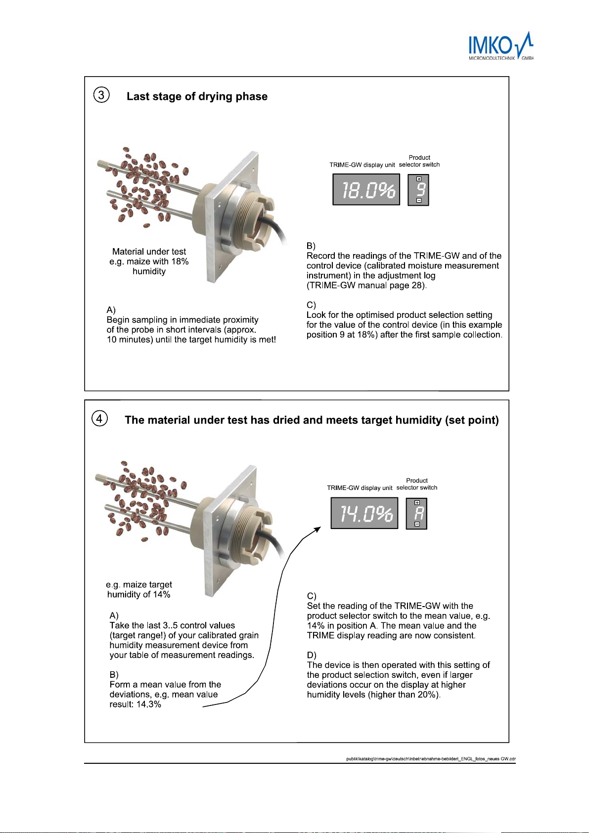
3 Initial operation and handling
3.1 Adjustment guidelines
Please read the detailed description first and subsequently use these guidelines as a checklist for
adjustments.
Extract samples from as close as possible to the probe.
Select switch position 1 on the product selection switch and do not change the setting
from this position until the moisture is near the target moisture (e.g. 3% above)!
Start up the dryer for the trial run, extract reference samples continuously approx.
every half hour and enter the reading together with the switch position in the adjustment protocol (Page 30).
As soon as the grain moisture has fallen to 3%
above the target value (for continuousflow dryers when the start-up phase is finished), extraction of reference samples must
be stepped up to take place at 15 minute intervals.
When drying is finished, the correct setting on the product selection switch must be
determined from the last reference values (less than 3% above the target value).
3.2 Adjustments for initial operation
The TRIME®-GW can only be adjusted when installed in the plant as the location and the bulk density
of the grain have a significant influence on moisture measurement. Adjustment must be carried out
separately for every product. The term “adjustment” refers, in this case, to the correct setting of the
product selector-switch.
Moisture measurement is dependent on the following parameters:
Location (e.g. metallic objects within the field of measurement)
Bulk density of the grain
Type of grain (product)
As soon as one of these parameters changes, another adjustment must be chosen using the product
selector-switch. The setting only has to be adjusted during operation when the product changes because the influence of the location remains constant and the bulk density of a given product remains
more or less constant as well.
®
3.2.1 Adjustment for plants with several TRIME
When the plant is only equipped with one TRIME
®
-GW, adjustments are made for the installationrelated influences at the same time as those for the grain product. Exactly the same procedure can be
followed as described in the next sections (3 to 3.2.7).
In plants with several probes, it may also be necessary to correct the deviations between the TRIME
GWs themselves. This is good policy only when all the TRIME
urement. If the installation-related constant deviation of 1-2% presents no problem, it is sufficient to
make an adjustment using the most important probe, e.g. at the discharge point.
As usually only one product selector-switch is installed for all TRIME
taneously applies to all the TRIME
®
-GWs. To carry out the extended adjustment for all TRIME®-GWs,
three steps must be taken:
1. Firstly, the TRIME
®
-GW that is most important for the drying operation must be selected. The probe at the discharge point, for example, is a potential candidate. Whichever one is chosen, it must
be possible to extract samples directly at the point where this probe is located.
-GW
®
-GWs are to give an absolute meas-
®
-GWs, its setting always simul-
®
-
_________________________________________________________________________________
17
Page 18

2. This
TRIME
®
-GW must be set as described in section 3 to 3.2.7. Simultaneously, the measurement data for all the other instruments must be gathered, too (section 3.2.5). The samples for this
should be extracted from as near to the probe as possible.
Using the differences between the readings of each of the instruments, the TRIME
3.
®
-GW can be
adjusted using the offset-correction connector as set out in section Fehler! Verweisquelle konnte
nicht gefunden werden..
3.2.2 The product selector-switch
®
The TRIME
-GW is ideally suitable for relative measurements. It can measure differences in moisture
up to the nearest 0.1%. The product selector-switch must be correctly adjusted to be able to take absolute measurements. A selection can be made from 15 different levels (1 to F). Level 0 is reserved
for diagnosis purposes. The individual levels differ from each other by 1% with 20°C and standard
calibration for corn and cereal.
In Level 1, the highest measurement appears, suitable for the lowest possible bulk density.
Level F provides the lowest measurement, corresponding to the highest possible density.
The appropriate level on the product selector-switch must be selected depending on the grain to be
measured and its bulk density specific to the plant.
3.2.3 Selection and application of the reference method
®
In order to adjust the TRIME
-GW on-line, an off-line method of measurement must be available to
serve as a reference. It must provide a high degree of absolute precision and function with large sample volumes
Most commercially available grain-moisture measuring systems leave a great deal to be desired regarding both of these aspects!
®
The TRIME
-GW measures the average value continuously over a volume of 1-2 litres. In moving
grain, the measurement volume acquired in the averaging time increases many times over. It therefore requires a lot of time and effort to check this very representative value with a reference instrument
that shows a sample quantity in the millilitre range. There are also factors that can affect measurement, such as temperature and conductivity, that can be ignored when using TRIME
®
-GW because of
the TDR method of measurement.
Thus, the most suitable method for determining the exact moisture of the grain is to use a drying oven.
Here, too, the sample volume is of decisive importance and should be at 0.5 litres.
When extracting the sample and taking reference measurements, the following must be observed:
The samples for the reference measurements should be extracted from as close as possible
to the probe. The distribution of moisture in the grain dryer can vary greatly.
When using a calibrated instrument with small sample volumes, several samples must be ex-
tracted and their arithmetical average calculated.
Please note that calibrated instruments can also produce incorrect measurements that can lie
between 2% in the lower and even 5% in the upper moisture range.
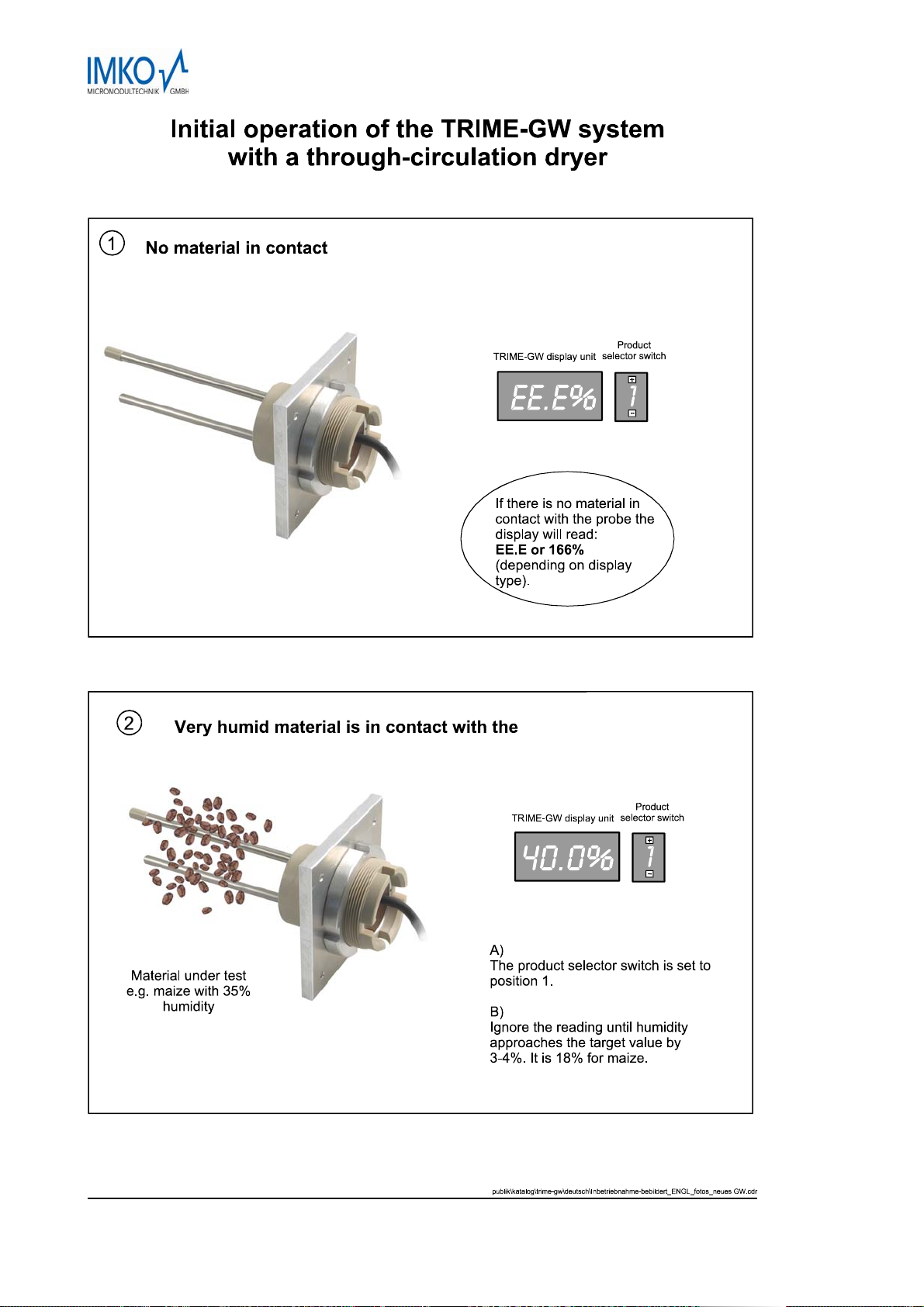
3.2.4 Initial operation
e the TRIME
Onc
the display type) should appear on the display as long as the dryer is empty or the probe prongs are
not completely immersed in grain. The current output of the TRIME
®
-GW has been turned on and after a few seconds, “EE.E“ or 166% (dependent on
®
-GW signalises this with a current
of 33.2 mA (or 30.56 mA at 4..20 mA).
After the dryer or the silo has been filled, the display must show a valid reading. The output current of
the TRIME
®
-GW is between 0 and 20 mA.
________________________________________________________________________________
18
Page 19

3.2.5 Recording measurement data in trial operation
The product selector-switch can only be adjusted in real operation or in realistic trial operation. The
following description is based on the implementation of the TRIME
®
-GW in a grain dryer as this in-
volves more complex adjustment than in the delivery or storage area.
As a general rule, only the moisture range close to the reference input is of significance for trial opera-
tion, i.e. when determining the switch position for maize, checking should be done at about 15%. It is
more important that the TRIME
importance whether TRIME
®
-GW is exactly correct in the lower area of measurement. It is of less
®
-GW measures 26% instead of 28% in the upper range! When extracting
a sample or checking the lower reference input (e.g. 15% ), a single sample is of course insufficient. A
single sample, possibly even extracted from quite a different point than in the direct vicinity of the probe, is not at all representative, i.e. several samples must be taken directly at the probe and averaged!
At the start of trial operation, the product selector-switch can be set to Level 1.
When all the preparations for extracting samples and measuring them have been made, the grain
dryer can be started up. Now, a sample of grain must be taken continuously, ideally every 15 minutes.
The TRIME
®
-GW reading and the selected switch position are to be noted simultaneously with
every extracted sample. This is compared with the appropriate offline-determined reference value,
which is also to be noted. As soon as the moisture is near the target moisture, the product selectorswitch should be set to the best possible value, which is the nearest to the reference value.
On page 30 you will find a ready-to-use form for entering the measurements.
Where continuous-flow
dryers are concerned, at least 10 to 20 measurements should be
available in the range between the minimum and maximum permissible moisture content after
drying. The measurements from the still very damp discharged grain during the charge phase
should be noted but not used for the purposes of adjustment.
For rotary dryers, only the measurements take towards the end of the drying process are of
relevance to adjustment. Here, too, at least 10 measurements are to have been documented.
Density and moisture distribution effects in the grain can cause too low measurements during
the first one to two hours. These values should not be used for the adjustment.
3.2.6 Setting the product selector-switch (adjustment)
The appropriate setting of the product selector-switch should be determined on the adjustment protocol. Only the measurements near the target moisture should be taken into account.
_________________________________________________________________________________
19
Page 20

3.2.7 An example
A continuous-flow dryer is to be set for maize. A TRIME
®
-GW has been installed whose probe is located in the direct vicinity of the discharge point. To start with, the product selector-switch is set to
Level 1. The dryer is started up and measurement recording commences. It is not until the moisture at
the discharge point falls below 18% that the measurements become of real interest and can be used
for the adjustment process. Analysis can start as soon as about 10 to 20 measurements are available
in the range from 12% to 18%. The following table shows that the best setting for the product selectorswitch is 7.
Table 6
Reference measurement TRIME-GW, Level 1 TRIME-GW deviation
17.9% 24.6% 1
17.3% 17.6% 8
17.8% 17.3% 8
17.1% 16.8% 8
16.8% 16.2% 8
16.5% 15.8% 8
15.8% 16.0% 7
15.1% 15.6% 7
14.5% 14.7% 7
13.9% 14.0% 7
13.3% 13.5% 7
________________________________________________________________________________
20
Page 21

3.3 Practical application
There is a variety of applications for the TRIME®-GW. On the one hand, it can be used for monitoring
the moisture of delivered grain. On the other, it can assist or automate the grain-drying process.
The appropriate position of the product selector-switch must be selected depending on the grain in
question and its density.
In-line measurement
of grain moisture
during the drying
process directly inside
the drying chamber.
T
R
I
M
E
-
G
W
Continuous monitoring
and recording during
grain deliv ery with
protocol print-out log issue
Networking via PC via
RS232/V24-interface for
processing the acquired
data in a grain mo isture
management system
T
R
I
M
E
-
G
Central Module
SM23U
RS232/V24
T
R
I
M
E
-
G
W
T
R
I
M
E
-
G
W
W
Integration into existing
control panels or
systems via standard
analogue interfaces
0...20 mA or 4..20mA
Figure 6: Schematic diagram of a drying plant showing possible applications of the TRIME-GW.
_________________________________________________________________________________
21
Page 22

3.3.1 Monitoring during grain delivery
The TRIME
®
-GW presents a means of continually measuring the moisture of the grain while it is being
delivered. This provides a moisture profile that can be recorded by a PC or a line printer. A display unit
can be connected as well for showing the values at any given moment. Legal regulations prevent TRI-
®
-GW being used instead of instruments that have been officially calibrated and authorised for
ME
goods traffic. The single measurements, usually based on very small samples, from such instruments
are supplemented by the continual, considerably more representative range of measurements taken
by the TRIME
®
-GW. This results in better quality control and enhances transparency.
3.3.2 Manual control of the grain dryer
In the case of manual or semi-automatic dryer-control systems, using the TRIME TRIME
®
--GW in
conjunction with a display unit can significantly improve drying results. Connecting a line printer or a
PC allows, in addition, the progression of drying to be documented and provides further potential for
optimising drying.
3.3.3 Automatic control of the grain dryer
®
This involves connecting the TRIME
eral TRIME
®
-GW in this case. The highest level of drying efficiency can be achieved in automatic con-
--GW to the controller’s actual-value input. It is ideal to use sev-
trol systems. We would be glad to assist you in selecting the most suitable controller for your particular
application.
________________________________________________________________________________
22
Page 23

4 Special functions
The possible adjustments and special functions of TRIME®-GW described in this section are only
likely to be required very rarely. Altering these settings or effecting the special functions may cause
the device to behave incorrectly!
The settings mentioned hereafter in this context can be changed by using:
a special configuring connector (available as an special accessory).
TRIME®-WinGWData Software (free of charge). Downloadable from our website:
www.imko.de
4.1 Operating the TRIME®-GW measurement systems in an intermittent
flow of material
A classic example of intermittent material flow is the use of the probe in the discharge chute, where
material is only present for a brief period shortly after a discharge. For this and similar cases, two options exist for controlling the measuring process:
1. Control of the measuring process via the adjustable internal time constants Queue-
FillingTime and Queue-DischargeTime in conjunction with the similarly adjustable internal
time constant Error66-Delay.
2. Control of the measuring process via an external digital input signal HaltM which, for example, can be produced by an PLC or a fill-level indicator.
4.1.1 Behaviour upon detection of air around the probe rods
®
The TRIME
rods. When this situation arise, the measuring process is stopped immediately and the existing reading “frozen”. After the adjustable time constant Error66-Delay has expired (cf. Table 1
the error 66: "Probe not fully immersed in grain" (cf. Table 1
is transmitted through the analogue output as "166.0". This is shown on the display unit as “E.EE” or
“166.0”, depending on the model.
Requiring special attention is the case where the periods in which the probe’s field of measurement
volume is only partially filled with the subject material, i.e. when the fill level “passes through” the probe’s field of measurement during filling or discharge. During these periods, the device would record an
excessively low reading because a proportion of the field of measurement is occupied by air, which
contains only negligible amounts of water. The materials’ characteristics differ too in their “dielectricity”
upon which water-content measurement is based. Individual readings such as these must therefore be
discarded and prevented from inclusion in the calculation of the overall measurement value.
This overall measurement value or reading is still carried out in the manner described as “fluid mean
value” in Section Fehler! Verw
Textmarke nicht definiert.. All that now has to be assured is that the determination of the mean value
is continued whilst using the set averaging time throughout the empty periods, and not started anew.
All that is not available during the empty period (plus the Queue-DischargeTime and the Queue-
FillingTime) are individual measurements that could contribute to the determination of the mean value.
The set “averaging time” is thus only composed of blocks of time in which valid individual
measurements can be taken.
-GW measurement system can detect when there is no more material around the probe
eisquelle konnte nicht gefunden werden. on page Fehler!
4.1.2 Control via the internal time constants Queue-FillingTime and Queue-
DischargeTime
During discharge, not only the measurement must be frozen after air around the probe rods has been
detected, but the individual readings of the past Queue-DischargeTim
_________________________________________________________________________________
e seconds, where the field of
23
Page 24

measurement was already less than full, must be discarded as well. Also, after the first wave of subject material has been detected around the probe rods, the individual readings of the future Queue-
FillingTim
e seconds must be discarded as well until the field of measurement is fully replenished
again.
The two time constants Queue-DischargeTime and Queue-FillingTime are adjustable and must be
determined by observing the relevant process.
If direct observation is not possible, suitable time constants can also be found by experimentation.
This can be done, for example, by determining those time constants from which point onwards no
further change can be detected in the reading when the discharge period starts or finishes. A certain
waiting period should also be added to the ascertained time values to be on the safe side and to absorb process fluctuations.
When performing a trial such as this, the subject material should be as homogenous as
possible and the averaging time low, though not less than 24s as the full functionality is
otherwise restricted (cf. Table 2
on page Fehler! Textmarke nicht definiert.).
It must be assured that an adequate measuring time remains for each measuring cycle during which
no individual readings are discarded. This is the reason why the two time constants cannot, in general,
be permanently set at their maximum value. This remaining time should not be less than 10s; 5s is
conceivable in extreme cases.
4.1.3 A side-effect when using the time constants Queue-FillingTime and Queue-
DischargeTime
The option of being able to discard individual past readings where required demands that a current
individual reading must first of all be temporarily stored until it becomes clear whether it is to be discarded or is to contribute to forming the mean value.
The (analogue or digital via PC) output reading is therefore “a glimpse into the past”:
under normal operation, the shift Queue-DischargeTime is a matter of seconds. In the transi-
tion from the "empty
phase" to the "full phase", individual seconds-long Queue-FillingTime
measurements are discarded first and then followed by the loading of seconds-long Queue-
DischargeTime intermediate memory, producing in this case a shift in seconds of "QueueDischargeTime + Queue-FillingTime".
4.1.4 Setting Queue-FillingTime
The Queue-FillingTim
e can be altered as follows by plugging in the configuration plug “TRIME
®
-GW
Queue-FillingTime”:
1. Insert the plug into the TRIME
®
-GW’s configuration socket. As soon as the plug is in place, the
analogue output (or the LED panel in measuring station) do longer displays the current measurement, but the current Queue-FillingTime setting in seconds as per the following table. Each position of the product selection switch corresponds to a certain Queue-FillingTime. If the configuration plug is removed at this point, the Queue-Filling Time stored in the unit will remain unchanged.
2. As soon as the setting/position of the product selection switch is changed for the first time, the
appropriate Queue-FillingTime value can be read on the display.
3. As soon as the plug is removed again, the unit adopts the value set at the product selection
switch. If the plug is removed when the switch is in the [0] position, the internal setting remains
unchanged.
________________________________________________________________________________
24
Page 25

Table 7
Queue-FillingTime/ Queue-DischargeTime Error66 delay Switch
0 Retain former setting Retain former setting
1 0.0 s (factory setting) 0.0 min = 0s
2 0.4s 0.1 min = 4s
3 0.8s 0.3 min = 20s (factory setting)
4 1.2s 0.7 min = 44s
5 2.0s 1.0 min = 60s
6 3.0s 1.5 min = 92s
7 4.0s 2.0 min = 120s
8 5.0s 3.0 min = 180s
9 6.0s 4.0 min = 240s
A 8.0s 5.0 min = 300s
B 10.0s 7.5 min = 452s
C 12.0s 10.0 min = 600s
D 14.0s 20.0 min = 1200s
E 16.0s 30.0 min = 1800s
F 20.0s 60.0 min = 3600s
4.1.5 Control via an external, digital input signal HaltM
The measuring process can also be halted by means of the external, digital input signal HaltM. This
interruption is immediate and is independent of control by the time constants Queue-FillingTime/ -
DischargeTime (see above). It is therefore theoretically even possible to combine the two means.
The appropriate signal can , for example, be created by an existing PLC that simultaneously operates
the discharge unit and therefore “knows” when material is present. At least just as suitable is a capacitive fill-level detector.
4.1.6 Electrical specification of the input signal HaltM / HaltM-In
The signal for halting the measurement process (HaltM) is transmitted from the PLC (or fill-level detector, etc.) to pin 12 (white/yellow) and looped from there through all the connected measuring transducers, thus making it available at each one.
®
The digital input directly to the TRIME
-GW measurement transducer’s 12-pin flanged bushing called
“HaltM-In” is hi-active and runs into pin 12 (white/blue) of each transducer (see also fig.5 on pg.16).
If this input is idle or has less than 0.7V above 0V (pin 22) running through it, a measurement is being
taken. If more than 3.8V (up to 24V and more) is applied, the measuring process is halted. Pin 22 (0V)
is identical to pin 3 (0V), i.e. the reference mass of the power supply.
HaltM-In (pin 21) of the measurement transducer is not wired as standard in the wiring-loom connector. If the control of the measuring process via HaltM is to be activated for one or more measuring
transducers, a bridge between the stated pin 21 (white/blue) and pin 19 (white/pink) must be created
in at least one of the cable connectors of this/these connector/s.
_________________________________________________________________________________
25
Page 26

4.2 Basis calibration after replacing system components
4.2.1 General notes regarding basis calibration
System components directly involved in the measuring process (probe, probe lead, transducer) are
aligned with each another by means of the basis calibration. Manufacturing tolerances influencing the
measurement reading are compensated for. New instruments are supplied with the basis calibra-
tion already performed. The process must be repeated if one of the system components mentioned above has been repaired or replaced. Calibration at the factory is not possible unless
the unit has been sent in with all components stated above.
Basis calibration involves taking two reference measurements in media of a known value ("reference
value") correcting any divergence of the unit from these reference values where necessary. TRI-
®
-GW calculates the correction values required for this ("offset" and "slope") itself and stored in
ME
non-volatile form in the instrument, i.e. they remain intact even when the power supply is switched off.
Air and dry glass beads are used as reference media.
The procedure is carried out using the GW basis-calibration set available as an optional extra and
comprising:
dry glass beads,
RS232 cable
Software WinCal
4.2.2 Reference values of the calibration media used for the basis calibration
The reference values listed below apply for the appropriate calibration media.
Table 10
Calibration medi-
um
Air -11.0 %
Dry glass beads +12.7 %
Reference value
before material calibration
and offset correction
(pseudo-transit time)
Permissible tolerance for test
measurements
0.5%
0.2%
4.2.3 Preparatory measures
The “dry glass beads” and probe required for the basis calibration must themselves be around room
temperature (18..24°C).
®
4.2.4 The procedure using the configuration plug “TRIME
-GW basis calibration”
1. To set the first reference value “air” the probe must be positioned in such a way that within a field
of at least 15 cm only air surrounds the probe rods.
It is by no means sufficient to place the probe on a table or something similar. The probe
Note:
can either be laid on the table so that the probe rods are fully overhanging the edge and the first
2..3 cm of the probe body are overhanging it as well. Alternatively, hold the it your hand at the
very rear (!) of the probe body to ensure that the hand does not invade the field of measurement
which also registers the front 3..4 cm of the probe body.
2. If the measurement was erroneous, the value “E.EE” is displayed instead of the reference value
"39.0". If this occurs, basis calibration must be repeated from step 1.
If the basis calibration procedure is not continued to take the second reference measure-
Note:
ment (“dry glass beads”) once the first reference measurement has been taken, only an offset correction has been performed, the slope remains unaltered. A “single-point basis calibration” such
as this can be used as a stopgap if no “dry glass beads” are available. A “two-point basis calibration” should be carried out later on though. Please also refer to the notes at the end of the section
on performing the basis calibration.
________________________________________________________________________________
26
Page 27

3. To obtain the second reference value “dry glass beads”, set the probe vertically into the vessel of
dry glass beads up to the lower rim of the probe body. Make sure that the probe lead exerts no
noticeable load on the probe when doing so in order to prevent creating an air space between the
probe rods and glass beads. Tap the outside of the vessel lightly to ensure that the beads sit
tightly around the rods. The glass bead vessel and the probe themselves must not be in contact
with any metal objec
ts (e.g. a metal table top).
Use only the glass beads we supply with the “calibration set” as otherwise completely dif-
Note:
ferent results may be obtained if others are used. The glass beads must be dry and clean and at
room temperature (18-24°C).
The probe, too, must be at room temperature as otherwise condensation may form on the probe
rods and thereby serious distort the results.
The diameter of the vessel used must be at least 18-20 cm; where probe rods are immersed completely, at least 3-4 cm must remain between the tips of the rods and the bottom of the vessel.
Reason:
The single-point correction shifts the measurement value by only one offset, the slope remains unchanged. In other words: the measurement value has been corrected only by a single additive constant (positive or negative), the sensitivity remains unchanged so the scale of the deviation can differ
depending on the moisture range in which the measurement is being taken.
The main factor influencing the offset is a differing length of the probe lead. The main factor influencing the slope is a differing length of the probe rods. There are, however, other parameters as well that
can influence both.
The single-point offset correction is to be regarded as no more than a stopgap because – arising from
the dielectric constant of air compared to that of the other material – it is not carried out in the range of
the target moisture for the material to be dried (generally ~8-14%) , but with a theoretical moisture
value of -11% (air). Deviations in the slope (sensor sensitivity) therefore have a considerably greater
effect at approx. 20 % on either side of a given moisture range.
1. If the readings deviate excessively from the reference values (cf. table at the top of section 4.2.2
Reference values of the calibration media used for the basis calibration), the basis calibration
must be repeated using the affected TRIME
®
-GW instruments.
_________________________________________________________________________________
27
Page 28

5 Technical data
Figure 7: Sizes and dimensions
connecting plug / screw connector
block:
power supply,
analogue output 0(4)..20mA
product selector switch,
IMP232-network bus.
Dimensions: 160 x 100 x 81 mm
________________________________________________________________________________
28
Page 29

Table 11
Power supply:
Power consumption:
Measuring range:
Standard deviation:
Repeatability:
Measurement transformer temperature range:
Probe temperature range:
Measuring period / -interval:
Interface:
Analogue output:
Cable length of probe:
Housing protection:
Probe protection:
9V..24V-DC
Dependent on the power supply:
200mA@24V-DC or 350..500mA@12..9V-DC
5..45 by
weight (b.w.) on a wet mass basis
(depends on the used material)
range 5..20 % b.w.: 0.6 % b.w.
range 20..45 % b.w.: 1 % b.w.
(depends on the used material)
0.3 % b.w. (depends on the used material)
-10..60 °C, extended range on request
0..127°C; temporarily up to 150°C
floating average with adjustable time interval (0.5s..20 min)
IMP232 MICRONET and RS232/V24
0 or 4..20 mA = 0 .. 100% gravimetric moisture
(max. load: 300 )
Standard 2.5m
Aluminium diecasting IP65
IP68 watertight casting
_________________________________________________________________________________
29
Page 30

6 TRIME-GW adjustment protocol
Serial number: ___________________
Installation location: ___________________
Product: ___________________
Plant: ___________________
Place: ___________________
Date Time Reference value of
the extracted sam-
ple
TRIME-GW reading Position of the
product selector-
switch
Comments
________________________________________________________________________________
30
Page 31

Notes
_________________________________________________________________________________
31
Page 32
________________________________________________________________________________
32
Page 33

_________________________________________________________________________________
33
Page 34
________________________________________________________________________________
34
Page 35
_________________________________________________________________________________
35
 Loading...