

Page 1

I:\publik\TECH_MAN\SONO-View\Englisch\Manual_SONO-View.docx
Operating Instructions
SONO-VIEW
Page 2

Manual SONO-VIEW Version 3_1 2017-05-24
Page 2
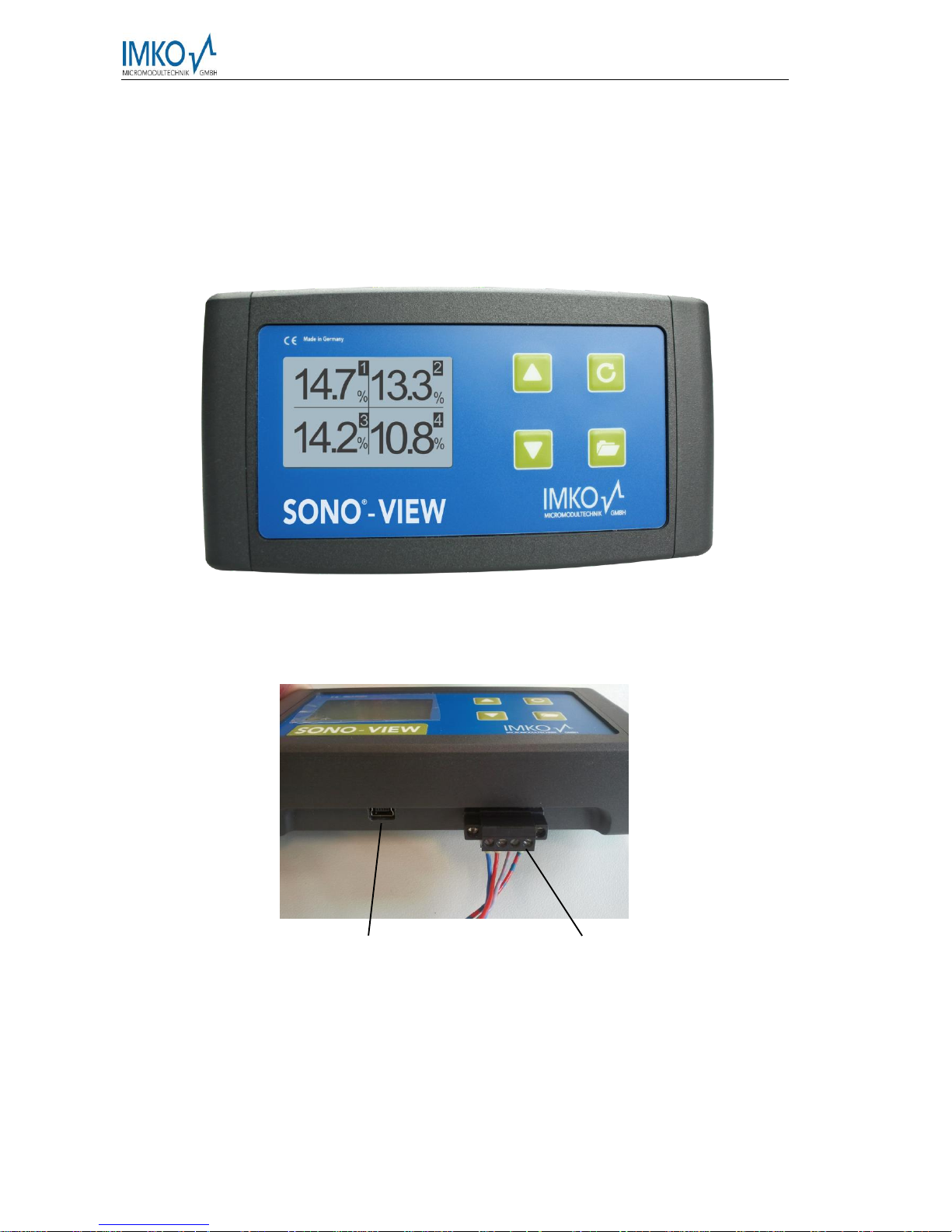
SONO-VIEW
Stand-alone display for the reliable control and configuration of processes using SONO moisture
probes. A total of up to 4 SONO probes can be monitored and the respective measurement values
presented at the LCD via a serial interface.
Thank you very much for your decision to purchase this IMKO product.
Should you have any questions in respect to this product, please contact our local
distribution partner or IMKO directly.
IMKO Micromodultechnik GmbH
Im Stöck 2
D-76275 Ettlingen
Germany
Phone: +49-7243-5921-0
Fax: +49-7243-90856
E-mail: info@imko.de
Internet: http://www.imko.de
.
Page 3

2017-05-24 Manual SONO-VIEW Version 3_1
Seite 3
Table of Content
1 General Notices ..................................................................................................................................5
1.1 Intended Use ..........................................................................................................................5
2 Control Elements / Connections ..................................................................................................6
2.1 Control Elements ...................................................................................................................6
2.2 Connections ............................................................................................................................6
3 Initial Commissioning ....................................................................................................................7
3.1 Safety Instructions .................................................................................................................7
3.2 Checking the Package Content for Completeness ..........................................................7
3.3 Connection ..............................................................................................................................7
3.3.1 Exemplary Connections ................................................................................................8
4 Operation ........................................................................................................................................9
4.1 Initial and New Installation ...................................................................................................9
4.2 Measurement Value Display ..............................................................................................10
4.4 Settings .................................................................................................................................11
4.4.1 New Set-Up ..................................................................................................................11
4.4.2 Language ......................................................................................................................11
4.4.3 Display Contrast...........................................................................................................12
4.4.4 Information about your SONO-VIEW........................................................................12
4.4.5 USB-IMP-Bridge ..........................................................................................................12
4.5 Probe Settings ......................................................................................................................13
4.5.1 Probe Info .....................................................................................................................14
4.5.2 Material Calibration .....................................................................................................14
4.5.3 Offset Balancing...........................................................................................................14
4.5.4 Averaging Mode ...........................................................................................................14
4.5.5 Averaging Parameters ................................................................................................15
1.1.1 Material Calibration ...................................................................................................17
1.1.2 Offset Adjustment .....................................................................................................23
1.1.3 Average Mode ............................................................................................................23
1.1.4 Average Parameters ..................................................................................................24
4.5.6 Basic Balancing ...........................................................................................................25
5 Technical Data .............................................................................................................................26
Page 4

Manual SONO-VIEW Version 3_1 2017-05-24
Page 4
Page 5

2017-05-24 Manual SONO-VIEW Version 3_1
Seite 5
1 General Notices
Please carefully read and get acquainted with these operating instructions.
Should any queries arise, please contact our service department under the contact data
depicted above. Do not, under no circumstances, attempt to open or repair the device
yourself. In the event of any warranty claims, please refer these to the retailer you purchased
the device.
The device is subject to technical and optical change within the scope of product
improvement.
1.1 Intended Use
This device was developed to serve as a display and configuration device for various IMKO
probes. Only the respectively intended probes may be connected to the device. The
connection of any probe which is not intended for the device, can lead to damage or the
destruction of this device and/or the connected probe.
Page 6
Manual SONO-VIEW Version 3_1 2017-05-24
Page 6
2 Control Elements / Connections
2.1 Control Elements
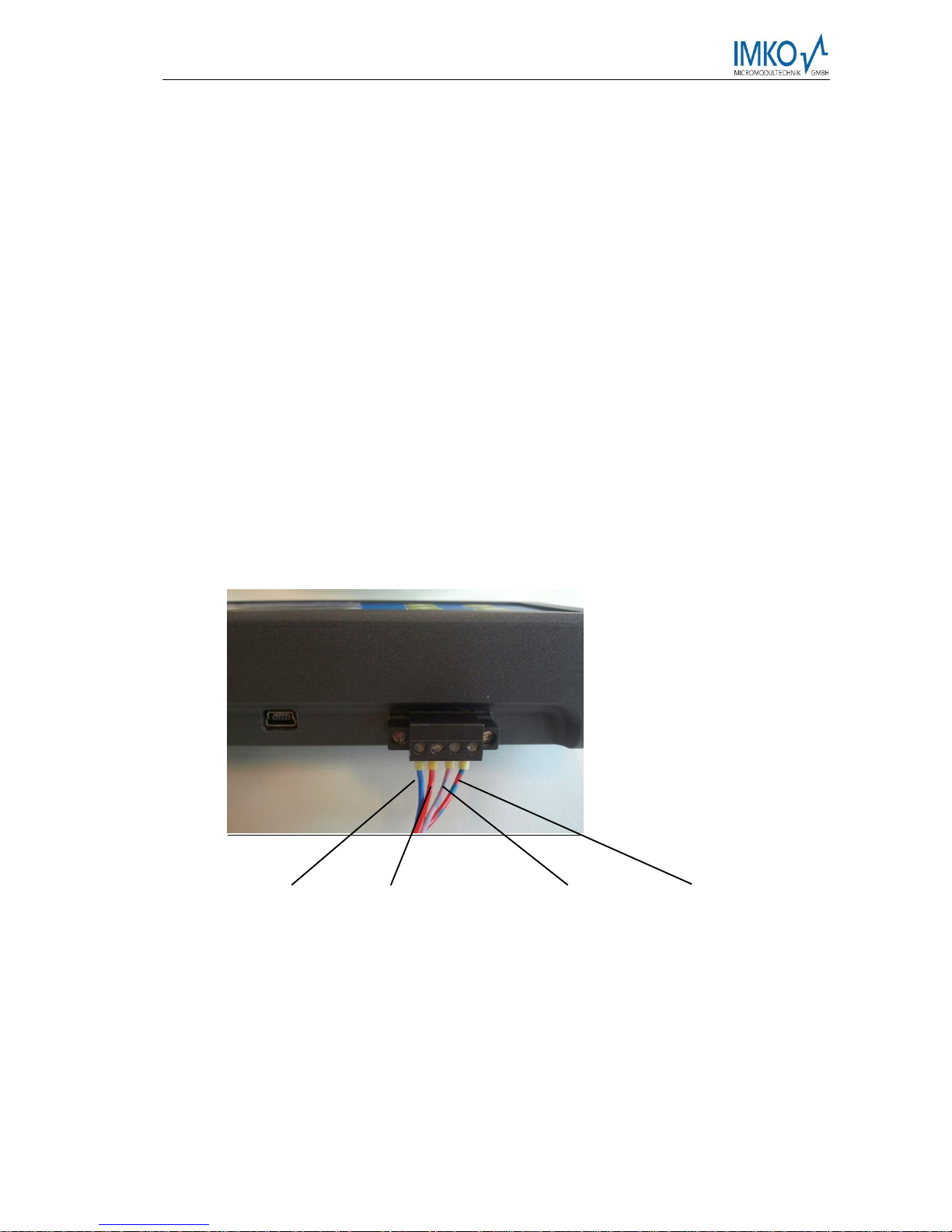
2.2 Connections
USB (Type-Mini B)
-USB-IMP-Bridge
-Firmware Update
-Supply Voltage
-Bus-Interface
Page 7
2017-05-24 Manual SONO-VIEW Version 3_1
Seite 7
3 Initial Commissioning
3.1 Safety Instructions
Attention: It is strictly necessary to read the General Notices contained under Item I at the
beginning of the operating instructions. Any not intended use of the device can lead to
damage to this device.
3.2 Checking the Package Content for Completeness
SONO-VIEW
Terminal Block
USB Cable (Type A Mini B)
3.3 Connection
For operation, the SONO-VIEW requires a supply voltage of 7...24V (approx. 80..30mA). A
joint ground wire together with the probes is not required. For the connection with the probes,
it is sufficient to merely connect the two bus lines „RT“and „COM“.
Notice: The SONO-VIEW is suited for the display and configuration of up to four
probes. Should more than four probes be connected, an error message
will be generated and the device cannot operate correctly.
0V
+7..24V
(RT) IMP-Bus
(COM) IMP-Bus
Page 8
Manual SONO-VIEW Version 3_1 2017-05-24
Page 8
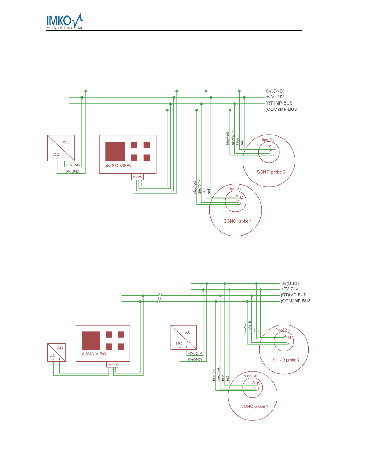
3.3.1 Exemplary Connections
Example 1: Connection of the SONO-VIEW with two SONO probes and one joint voltage
supply source.
Example 2: Connection of the SONO-VIEW with 2 SONO-probes merely via IMP-bus.
SONO-VIEW and the probes dispose of their voltage supply. This may be
useful, if the distance between the measuring equipment and the display
device is considerable.
Page 9
2017-05-24 Manual SONO-VIEW Version 3_1
Seite 9
4 Operation
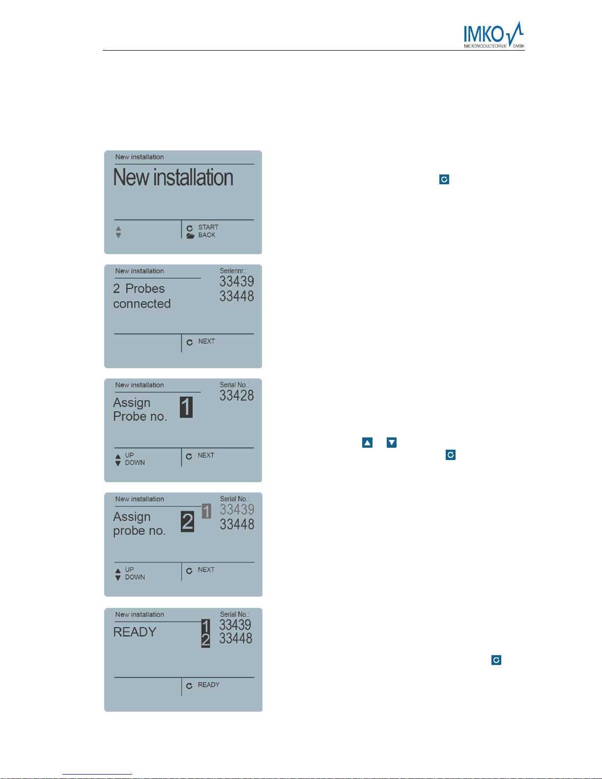
4.1 Initial and New Installation
At the initial connection to your probe-network, it is necessary to set the same up,
respectively follow an installation procedure at the SONO-VIEW.
For this purpose, the device will scan the IMB bus for
connected probes.
Initiate the installation with the button .
After an instant, the serial numbers of all connected
probes are listed in the display.
In order to maintain the clarity within the administration
of the probes, the SONO-VIEW operates on the basis
of assigned probe numbers (1...4).
These must be allocated to the detected serial numbers
in the next step. For each probe number, select a serial
number using the / buttons and subsequently
acknowledge the same with the button .
Repeat this procedure until all serial numbers have
been allocated a probe number.
After completion of the above steps, all probe numbers
will be presented once more together with the
respectively allocated serial numbers in ascending
order.
Complete the installation process with the button .
Page 10

Manual SONO-VIEW Version 3_1 2017-05-24
Page 10
Notice: The SONO-VIEW is suited for the display and configuration of up to four
probes. Should more than four probes be connected, an error message
will be generated and the device will not be able to operate properly.
After completion of the installation process, the SONO-VIEW will re-start, verify the
connected probes, and will immediately commence to call up the measurement values.
4.2 Measurement Value Display
The SONO-VIEW immediately commences to call up and display the measurement values
after start-up. This is performed in a 500 ms cycle. Depending on how many probes are
connected, from one to four, the following displays will be presented.
The moisture value in percent and the respective probe number is always presented. If two
or three probes are connected, the temperature measured by the probe is additionally also
presented. In the event that only one probe is connected, the calibrated radar run-time is also
presented.
If more than one probe is connected to the SONO-VIEW, there is an option to change the
display. For this purpose, actuate the buttons / . Subsequently, all connected individual
probes are presented consecutively. For the purpose of allocation, the probe number is
always also presented in the upper section. If this form of display is maintained for a longer
period, the same will be assumed as „Standard“. In this case, the SONO-VIEW will present
this set measurement display form after a re-start.
Page 11

2017-05-24 Manual SONO-VIEW Version 3_1
Seite 11
4.4 Settings
Actuate the button while the measurement display is active and you will reach the setup
menu. Here, you are enabled to perform various settings and call up information regarding
the SONO-VIEW.
The setup menu features the following structure:
Setting
Description
New Setup
Enables a new detection of connected probes
Language
Setting of the language
Display Contrast
Setting of the display contrast
About SONOVIEW
Serial number and further information regarding your SONO-VIEW
Info
Support information
USB-IMP-Bridge
Enables the comfortable configuration of your probes via PC
Set the desired setting using the buttons / . By actuating the button , you can
subsequently enter the selected setting. Actuate the button again in order to exit the setup
menu.
4.4.1 New Set-Up
See Section 4.1 „Initial and New Installation“
4.4.2 Language
The selection of the language is performed with the buttons / . By actuating the button
, the selected language is set as the standard language. To exit the menu item “Language”,
actuate the button .
Page 12

Manual SONO-VIEW Version 3_1 2017-05-24
Page 12
4.4.3 Display Contrast
A bar containing a grey colour gradation will appear.
Set the contrast using the buttons / in a manner
that enables you to recognise all grades. Store the set
value with the button . To exit the menu item „Display
Contrast“, actuate the button .
4.4.4 Information about your SONO-VIEW
The device will present the serial number, the HWversion, the IBT version, as well as the firmware
version. By actuating the button , the device will
present further status information such as the currently
connected probes and system voltage values. To exit
the menu item „About SONO-VIEW“, actuate the button
.
4.4.5 USB-IMP-Bridge
As soon as this menu item is called up, the SONO-VIEW changes into a transparent data
mode. All data packets will be now redirected from the USB interface directly on to the IMPbus and vice versa. This enables a comfortable configuration of the probes via a connected
PC without the necessity of additional hardware. For this purpose, please download the free
software „SonoConfig“as well as the respective operating instructions available on the IMKOhomepage.
Connect the SONO-VIEW to the PC using the provided USB cable. The SONO-VIEW will
connect with the PC as a virtual serial interface (COM-Port). The respectively required driver
is usually automatically installed by all currently used Windows versions. Should the driver
not be automatically installed, please download the driver under:
http://www.ftdichip.com/Drivers/VCP.htm.
Page 13

2017-05-24 Manual SONO-VIEW Version 3_1
Seite 13
Notice: As long as the SONO-VIEW is in the USB-IMP-Bridge modus, no
measurement values are queried by the probe. The probes however
continue to measure and issue the measurement value at the analogue
output.
Actuate the button in order to exit the menu item „USB-IMP-Bridge“.
4.5 Probe Settings
The SONO-VIEW offers the option to comprehensively configure the connected probes even
without PC. Settings such as offset displacements or the selection of a material-specific
calibration can be simply adjusted with the buttons / .
The menu “Probe Settings” respectively offers the following options:
Setting
Description
Probe Info
Presents information regarding the connected probe
Material Calibr.
Selection of a material-specific calibration
Offset balancing
Displacement of the measurement value
Average Mode
Setting of the method of averaging
Average Paramet
Setting of the parameters of the set averaging method
Basic balancing
„Zero Value“ calibration of the probe in ambient air
To reach the probe settings, select the individual probe display mode for the probe intended
for configuration in the measuring display using the / buttons (also see Item 4.2). By
actuating the button , the probe setting of the currently used probe is called up.
Notice: It is only possible to configure one probe at a time. Should several
probes require to be adjusted, the procedure must be respectively
repeated for these other probes.
Attention: Ensure that the correct probe is set before commencing with adjusting the
parameters.
Attention: The SONO-VIEW offers the option to access the measuring parameters of the
probe. Before adjusting any parameters, please inform yourself precisely in
regard to the function of the same in the respective probe manual. Any
performed changes may affect the measurement value, the accuracy, and the
measuring rate.
Page 14

Manual SONO-VIEW Version 3_1 2017-05-24
Page 14
4.5.1 Probe Info
If this menu item is selected, various information of the probe is called up and displayed.
You can exit the menu item „Probe Info” with the button
.
4.5.2 Material Calibration
The menu item „Material Calibration“enables to adjust a material-specific calibration stored in
the probe. This enables to significantly increase the accuracy of the measurement. There are
up to 15 material-specific calibrations deposited in the firmware of a SONO probe. These are
presented here and can be selected with the buttons / . The character „1“ set in front of
a calibration hereby points out the current standard calibration. Store the selected calibration
as standard in the probe using the button . The set calibration will subsequently be stored in
the non-volatile memory of the probe. The menu item “Material calibration” is exited by
actuating the button .
4.5.3 Offset Balancing
In order to compensate measurement errors e.g. due to density deviations in the material or
due to the installation conditions, there is an option to perform a linear displacement of the
measurement value. This is the purpose of this menu item. It is possible to displace the
measurement value between -10 and +10 percent points. The set displacement is stored in
the probe and will subsequently also affect the analogue output. The setting is maintained in
a traceable manner.
Adjust the offset to the desired value using the buttons
/ . Subsequently store the set value in the probe
with the button . You can exit this menu item with the
button .
4.5.4 Averaging Mode
This menu item enables the activation, respectively the changing of a measurement value
establishment in the probe. IMKO moisture probes respectively offers the following options:
Mode CS: (cyclic-successive) Without averaging function intended for very short measuring
processes in a range limited to seconds (e.g. 5…20 seconds) at which up to 100
measurements are performed internally per second at a cycle time of 250 milliseconds at the
Page 15

2017-05-24 Manual SONO-VIEW Version 3_1
Seite 15
analogue output. The operating mode CS also serves for the collection of raw values without
averaging and filter functions.
Mode CA: (cyclic average filter) Standard averaging for relatively fast but continuous
measurement processes with filtering and an accuracy of up to 0.1%.
Mode CF: (cyclic floating average with filter) Floating averaging for very slow and continuous
measurement processes with filtering and an accuracy of up to 0.1%.
This is suited for applications such as within a fluid bed dryer, on the conveyor belt, etc.
Mode CK: (cyclic with Kalman filter) suitable for complex application
Mode CC: (cyclic cumulated) with automatic summation of the moisture-quantity
measurements in one batch operation.
Notice: Please respectively also read the further information contained in your probe
operator manual.
Set the desired „Average Mode“ with the buttons /
and subsequently set the set mode as standard with
the button . Once this is performed, the setting is
stored in the probe. You can exit the menu item
„Average Mode“ with the button .
4.5.5 Averaging Parameters
Depending on the set „Averaging Mode“, there are various „Average Parameters“available
for control purposes.
Averaging Mode
Available Parameters
CA – Cyclic Average
Average Time
Filter Upper Limit Offset
Filter Lower Limit Offset
Upper Limit Keep Time
Lower Limit Keep Time
CK – Cyclic Kalman
Kalman with Boost
Average Time
Filter Upper Limit Offset
Filter Lower Limit Offset
Upper Limit Keep Time
Lower Limit Keep Time
Q-Parameter
R-Parameter
K-Parameter
Moisture Threshold
Boost
Offset
Page 16

Manual SONO-VIEW Version 3_1 2017-05-24
Page 16
CF - Cyclic Floating
Average Time
Filter Upper Limit Offset
Filter Lower Limit Offset
Upper Limit Keep Time
Lower Limit Keep Time
CC - Cyclic Cumulate
Moisture Threshold
No Material Delay
Notice: Please respectively also read the further information contained in your
probe operator manual.
Attention: Before adjusting a parameter, please precisely inform yourself in regard to the
function of the same. Any performed change may affect the measurement
value, the accuracy, and the measuring rate.
The parameters are dynamically enabled with the set „Average Parameter“.
The buttons / serve for the navigation
between the individual parameters. The
current value of the selected parameter is
presented in the lower left section of the
display. To change the value, actuate the
button .
The value will now appear enlarged in the
display. Adjust the value with the buttons
/ and subsequently assume the same
with the button . You also have the option
to exit the entry with the button without
performing any change to the value. Repeat
this procedure for all parameters intended for
adjustment.
As soon as you have performed all
adjustments as desired, select the item
„Save“ and acknowledge the same with the
button . Now, the parameters are written
back into the probe and are immediately
active.
You can exit the menu item „Average
Parameters „with the button without
saving the same. Hereby, all performed
changes are deleted!
Page 17

2017-05-24 Manual SONO-VIEW Version 3_1
Seite 17
1.1.1 Material Calibration
The "Material Calibration" menu item allows you to set a material-specific calibration stored
in the probe. In addition, you have the possibility to carry out your own calibrations in order
to be able to measure special materials.
Der Menüpunkt „Materialkalibrierung“ ermöglicht es, eine in der Sonde gespeicherte
materialspezifische Kalibrierung einzustellen. Außerdem haben Sie hier die Möglichkeit
eigene Kalibrierungen durchzuführen, um auch spezielle Materialien vermessen zu können.
Note: Pressing the key briefly will take you to the previous menu point. By pressing the
key for a long time, regardless of which material calibration sub-point is currently active,
you return to the probe setting menu.
After selecting the menu item "Material cal.", use the
/ buttons to "CHOOSE" one of the 15 stored
material-specific calibrations or "CHANGE" to perform
a new calibration on one of the 15 calibration memories.
The corresponding sub-point is selected with the key
and the key leaves this menu point.
1.1.1.1 Choose Calibration Curve
The sub-item "Select" allows you to select between up to 15 material-specific calibrations.
Use the / buttons to select between the materialspecific calibrations. The "!" shows the current standard
calibration before calibration. Save the selected
calibration with the button as a standard in the
probe. The setted calibration curve is not stored in the
probe. By pressing the key , you can leave this subitem "Select" again.
1.1.1.2 Change
The "CHANGE" sub-point allows you to perform a 1-point calibration or 2-point calibration.
Use the / buttons to toggle between 1-point
calibration and 2-point calibration. The corresponding
procedure is executed with the key and the key is
for finishing this procedure.
Page 18

Manual SONO-VIEW Version 3_1 2017-05-24
Page 18
1.1.1.2.1 1-Point Calibration
With this material calibration option, a linear equation (f (x) = mx + b) is calculated with the
dry density. So it is necessary to have the dry density of the measured material before
activating this option. A reference moisture content and the tp value (propagation time of the
radar signal) which can be measured or set at the point of the reference moisture. Even if a
polynomial of higher degree is useful for obtaining greater accuracy, the linear equation is
often sufficient to achieve very good results.
Note: To perform a 1-point calibration, you need a material sample as well as the dry density
of the material to be measured. The moisture value has to be determined with another
method like kiln drying or similar, before activating this calibration procedure.
Procedure:
At the beginning of the calibration, the selected
calibration memory (01 - 15) has to be overwritten with
the / buttons. Press the button to accept the
setting and press the button to move to the previous
item.
The percentage reference moisture of the material to be
measured, must then be set with the / buttons.
Press the button to accept the setting and press the
button to move to the previous item.
In the following step, the dry density of the material to
be measured must be set with the / buttons.
Press the button to accept the setting and press the
button to move to the previous item.
In the next step, the tp value (radar signal time) has to be determined by a measurement with
the connected probe or by manual setting with pre-determined tp values.
Page 19

2017-05-24 Manual SONO-VIEW Version 3_1
Seite 19
Use the / buttons to select between "Measure"
and "Set". The corresponding sub-point is selected
with the key and the key can be used to switch
to the previous point.
Measure tp:
Press the key to start the tp measurement and press
the key to move to the previous point.
After starting the measurement with the key , the
mean value of 10 measured tp values is formed. During
this phase, the SONO-View does not respond to any
input.
After completion of the measurement, the tp mean
value is displayed. Press the key to accept the
measured value and press the key to move to the
previous point.
Set tp:
The tp value can be adjusted manually using the
/ buttons. Press the button to accept the
setting and press the button to move to the previous
item.
Page 20

Manual SONO-VIEW Version 3_1 2017-05-24
Page 20
In the last step, the calibration settings can be saved with "Save" to the previously selected
calibration memory location, or can be canceled with "Discard".
Note: After performing "Save", the original material calibration is preceded by an "OWN:",
indicating that this is a specially prepared material calibration.
Use the / buttons to toggle between "Save" and
"Discard". The corresponding sub-point is selected with
the key and the key can be used to switch to the
previous point.
1.1.1.2.2 2-Point Calibration
For the 2-point calibration, a linear equation (f (x) = mx + b) can be calculated with two
moisture values of a material and the corresponding tp values (running times of the radar
signal) which are measured or set at the respective material moisture. Even if a polynomial
of a higher degree is useful for obtaining greater accuracy, the straight line equation is often
sufficient to obtain very good results.
Note: In order to perform a 2-point material calibration, you need two material samples
with different moisture values. Moisture values should be determined by
another method like kiln drying or similar, before activating this calibration
procedure. The sequence - "lower moisture value" (more dry material) and
then - "upper moisture value" (moist material) must be observed.
Procedure:
After selecting the menu item "Material cal.", use the
/ buttons to "CHOOSE" one of the 15 stored
material-specific calibrations or "CHANGE" to perform
a new calibration on one of the 15 calibration
memories. The corresponding sub-point is selected
with the key and the key leaves this menu point.
Page 21
2017-05-24 Manual SONO-VIEW Version 3_1
Seite 21
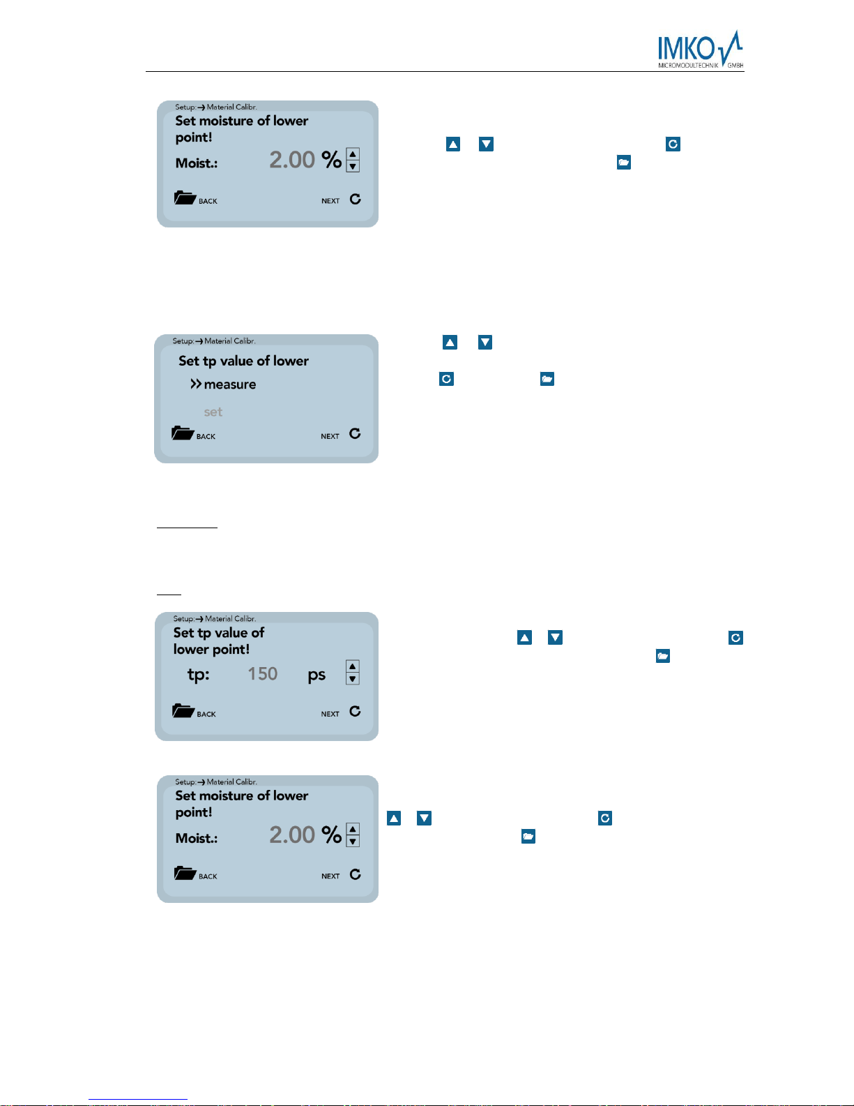
Subsequently, the percentage moisture value at the
lower point of the material to be measured, must be set
with the / buttons. Press the button to accept
the setting and press the button to move to the
previous item.
In the next step, the tp value (radar signal time) has to be determined by a measurement with
the connected probe at the lower moisture point or by manual setting with pre-determined
tp values.
Use the / buttons to toggle between "Measure"
and "Set". The corresponding sub-point is selected with
the key and the key can be used to switch to the
previous point.
Measure:
See point „1.1.1.2.1 1-Point Calibration(Measure)“.
Set:
The tp value of the lower moisture point can be setted
manually using the / buttons. Press the button
to accept the setting and press the button to move to
the previous item.
The percentage reference moisture of the lower point of
the material to be measured, must then be set with the
/ buttons. Press the button to accept the setting
and press the button to move to the previous item.
The next step is to determine the tp value (radar signal time), the upper moisture value, a
measurement (with the connected probe) or manual setting.
Page 22

Manual SONO-VIEW Version 3_1 2017-05-24
Page 22
Use the / buttons to select between "Measure"
and "Set". The corresponding sub-point is selected with
the key and the key can be used to switch to the
previous point.
Measure:
See point 1.1.1.2.1 1-Point Calibration(measure)
Set:
The tp value for the upper moisture value can be
adjusted manually using the / buttons. Press the
button to accept the setting and press the button
to move to the previous item.
In the last step, the calibration settings can be saved with "Save" to the previously selected
calibration memory location, or can be canceled with "Discard".
Note: After performing "Save", the original material calibration is preceded by an "OWN:",
indicating that this is a specially prepared material calibration.
Use the / buttons to toggle between "Save" and
"Discard". The corresponding sub-point is selected with
the key and the key can be used to switch to the
previous point.
Page 23

2017-05-24 Manual SONO-VIEW Version 3_1
Seite 23
1.1.2 Offset Adjustment
For compensation of measurement deviations caused by e.g. density fluctuations in the
material or by installation conditions, it is possible to linearly shift the measured value. This
menu item is used for this purpose. You can move the measured value between -10 and +10
percentage points. The set displacement is stored in the probe and then also affects the
analog output. The setting remains comprehensible.
Use the / buttons to adjust the offset to the
desired value. Then save the set value with the button
in the probe. Press the key to exit this menu
item.
1.1.3 Average Mode
This menu item allows you to switch on or switch over a measurement averaging in the
moisture probe. The configuration of SONO- probe is preset in the factory before delivery.
SONO moisture probes offer the following options:
Mode CS: (Cyclic-Successive) For very short measuring processes (e.g. 2…10 seconds)
without floating average and without filter functions, with internal up to 100 measurements
per second and a cycle time of 250 milliseconds at the analogue output. Measurement mode
CS can also be used for getting raw data from the SONO-probe without averaging and
filtering.
Mode CA: (Cyclic-Average-Filter) For relative short measuring processes with continual
average value, filtering and an accuracy of up to 0.1%
Mode CF: (Cyclic-Float-Average) for continual average value with filtering and an accuracy
of up to 0.1% for very slowly measuring processes, e.g. in fluidized bed dryers, conveyor
belts, etc.
Mode CK: (Cyclic-Kalman-Filter with Boost) Standard setting for SONO-MIX for use in fresh
concrete mixer with continual average value with special dynamic Kalman filtering and an
accuracy of up to 0.1%.
Mode CC: (Cyclic Cumulated) with automatic summation of a moisture quantity during one
batch process.
Mode CH: (Cyclic Hold) similar to Mode CC but without summation.
Mode CH is recommended for applications in the construction industry. If the SONO-
probe is installed under a silo flap, Mode CH can measure moisture when batch cycles are
very short, down to 2 seconds. Mode CH executes an automatic filtering, e.g. if dripping
water occurs.
Note: Please also refer to the information in your Probe User's Manual
Page 24

Manual SONO-VIEW Version 3_1 2017-05-24
Page 24
Use the / buttons to set the desired "Average
Mode" and then set the mode as the default with the
button . The setting is then stored in the probe. Press
the button to exit the "Average Mode" menu item.
1.1.4 Average Parameters
Depending on the "average mode" set, various "average parameters" are available for control
purposes.
Average Mode
Available Parameters
CA – Cyclic Average
Average Time
Filter Upper Limit Offset
Filter Lower Limit Offset
Upper Limit Keep Time
Lower Limit Keep Time
CK – Cyclic Kalman
Kalman with Boost
Average Time
Filter Upper Limit Offset
Filter Lower Limit Offset
Upper Limit Keep Time
Lower Limit Keep Time
Q-Parameter
R-Parameter
K-Parameter
Moisture Threshold
Boost
Offset
CF - Cyclic Floating
Average Time
Filter Upper Limit Offset
Filter Lower Limit Offset
Upper Limit Keep Time
Lower Limit Keep Time
CC - Cyclic Cumulate
Moisture Threshold
No Material Delay
Note: Please also refer to the information in your Probe User's Manual.
Caution: Before you adjust a parameter, please be sure to check its function. A change can
affect the measured value, the accuracy and the measurement rate.
Page 25

2017-05-24 Manual SONO-VIEW Version 3_1
Seite 25
The parameters are activated dynamically with setting the "Average parameter".
Use the / buttons to navigate between
the individual parameters. The lower right
area shows the current value of the selected
parameter. To change the value, press the
key .
The value now appears in the display. Use
the / buttons to adjust the value and
press the button to accept. You can also
leave the entry without changing the value.
Repeat the procedure for all parameters to be
adjusted.
If you have adjusted all parameters as
desired, select "SAVE" and confirm with the
key . Now the parameters are written back
into the probe and are now active.
You can leave the menu item "Average
Parameters" with the button without
saving. Than all changes will be lost!
4.5.6 Basic Balancing
At the exchange of a sensor head, due to deviating cable lengths, it may be necessary to
perform a basic balancing in air. Hereby, the moisture measurement value of the probe is realigned to the correct „Zero Value“.
Actuate the button in order to start the basic
balancing. The balancing will be performed
subsequently.
Page 26

Manual SONO-VIEW Version 3_1 2017-05-24
Page 26
Attention: In order to exclude the occurrence of a faulty air calibration, the sensor must
be dry and free of any material during basic balancing.
The notice „Please wait „will be generated in the
display. The procedure lasts approximately 30 seconds.
5 Technical Data
Power Supply
+7 .. 24V DC / 0.7W
Operating
Temperature
0 .. 50°C
Dimensions
145mm x 75mm x 34 mm
Weight
153g
Mounting
Cap Rail (optional)
Interfaces
IMP-Bus (RT / COM)
USB Mini-B (galvanically isolated)
Page 27

Page 28

www.imko.de
Precise Moisture Measurement
in hydrology, forestry, agriculture, environmental and earth science,
civil engineering, as well as individual applications!
 Loading...