

Imi Tech IMB-7017G, IMB-7011G, IMB-7016G, IMB-7018G, IMB-7020G User's Operation Manual
...
AMAZON SERIES
USER MANUAL VERSION 1.23
Released Jul. 2012
#616, Mega Valley, Gwanyang 2-dong, Dongan-gu,
Anyang-si, Gyeonggi-do, 431-767, Korea
Phone 82-31-423-9801 Fax : 031-423-9803
User Operation Manual
For GigE Cameras IMx-xxxxG Models

Legal Notice.
For Customers in U.S.A.
This equipment has been tested and found to comply with the limits for a Class B digital device, pursuant to Part 15 of the FCC
Rules. These limits are designed to provide reasonable protection against harmful interference when the equipment is operated
in a commercial environment. This equipment generates, uses, and can radiate radio frequency energy and, if not installed and
used in accordance with the instruction manual, may cause harmful interference to radio communications. Operation of this
equipment in a residential area is likely to cause harmful interference in which case the user will be required to correct the
interference at his own expense. You are cautioned that any changes or modifications not expressly approved in this manual
could void your authority to operate this equipment. The shielded interface cable recommended in this manual must be used
with this equipment in order to comply with the limits for a computing device pursuant to Subpart J of Part 15 of FCC Rules.
For customers in Europe
This apparatus has been certified to meet or exceed the standards for CE compliance per the Council Directives. Pertinent
testing documentation is available for verification.
For customers in Canada
This apparatus complies with the Class B limits for radio noise emissions set out in the Radio Interference Regulations.
Pour utilisateurs au Canada
Cet appareil est conforme aux normes Classe B pour bruits radioélectriques, spécifiées dans le Règlement sur le brouillage
radioélectrique.
Life support applications
These products are not designed for use in life support appliances, devices, or systems where malfunction of these products can
reasonably be expected to result in personal injury. Allied customers using or selling these products for use in such applications
do so at their own risk and agree to fully indemnify allied for any damages resulting from such improper use or sale.

Before You Start
This manual should help you in the installation and setting up of the camera; and we recommend that you carefully follow the
instructions described. To ensure that your warranty remains valid, please read the manual carefully before using the camera.
DO NOT disassemble, modify or repair the camera. There are no user serviceable parts inside and disassembling the camera
may void the warranty. For prevention of fire or electric shock, DO NOT removes screws or covers from the camera.
Operation in a wet environment is NOT recommended and the camera SHOULD NOT be exposed to rain or moisture.
For prolong life and the protection of the camera’s CCD, do not point the camera directly at the sun or a strong spotlight which
may result in CCD blooming and permanent damage.
DO NOT operate the camera beyond the operation temperature range stated and AVOID usage in conditions exceeding 90%
humidity.
DO NOT use an unregulated power supply source to prevent damage to the camera’s circuits.
Use soft materials such as lens tissue or cotton tipped applicator with ethanol for CCD faceplate cleaning ONLY when necessary
and AVOID contact with fingers or any hard object. Do not use solvent, abrasives or detergent when cleaning the camera body.
Warranty shall be voided for improper use of the camera or fault caused by the user or damage caused by other equipment due
to negligence
Warranty
IMI TECH warrants the original components free of defects for one year from purchase date. This warranty covers failures and
damage due to defect, which may occur during normal use. It does not cover damages or failure resulting from mishandling,
abuse, misuse or modification. An RMA number must be obtained in advance for every repair or replacement.
Disclaimer
The information in this document has been carefully checked and is believed to be reliable. However, IMI TECH assumes no
responsibility for inaccuracies. There is no legal obligation to document internal relationships in any functional module of its
products, in either hardware or software
Copyright
All the materials in this document are protected by copyright and other laws for intellectual property. They are not allowed to be
copied, reproduced or modified for any use without the permission of IMI Tech. IMI TECH reserves the right to make changes in
specifications, functions or designs at any time and without any notice. The company names in this document may be the
trademarks and trade-names of their respective owner; and are hereby acknowledged.
Copyright © 2008 IMI TECHNOLOGY CO.,LTD. All rights reserved.

Amazon Series Operation Manual
1. Introduction .................................................................................................................. 1
1.1. Overview ............................................................................................................................................................... 1
1.2. Components .......................................................................................................................................................... 2
1.3. Optional Accessories............................................................................................................................................... 3
1.4. Dimension and Description ..................................................................................................................................... 4
1.5. Camera Interface ................................................................................................................................................... 6
1.5.1. Trigger/Strobe/Power Connector Port ............................................................................................................. 6
1.5.2. Status LED ................................................................................................................................................... 7
1.5.3. Camera Power Requirement .......................................................................................................................... 7
1.5.4. Power Adapter connection ............................................................................................................................. 7
1.6. Electrical Operating Condition ................................................................................................................................. 7
1.7. Pixel Data .............................................................................................................................................................. 8
1.8. Environmental Requirements. ............................................................................................................................... 10
2. Basic Installation ........................................................................................................ 11
2.1. Recommended System Requirement ..................................................................................................................... 11
2.2. Hardware Installation ........................................................................................................................................... 11
2.3. Software Installation ............................................................................................................................................ 12
3. AMAZON Series Camera Specifications. ...................................................................... 13
3.1. Black and White Camera ....................................................................................................................................... 13
3.1.1. IMB-7050G Specification.............................................................................................................................. 13
3.1.2. IMB-7020GH Specification ........................................................................................................................... 14
3.1.3. IMB-7020G Specification.............................................................................................................................. 15
3.1.4. IMB-7018G Specification.............................................................................................................................. 16
3.1.5. IMB-7017G Specification.............................................................................................................................. 17
3.1.6. IMB-7016G Specification.............................................................................................................................. 18
3.1.7. IMB-7015G Specification.............................................................................................................................. 19
3.1.8. IMB-7012G Specification.............................................................................................................................. 20
3.1.9. IMB-7011G Specification.............................................................................................................................. 21
3.2. Color Cameras ..................................................................................................................................................... 22
3.2.1. IMC-7050G Specification .............................................................................................................................. 22

3.2.2. IMC-7020GH Specification ........................................................................................................................... 23
3.2.3. IMC-7020G Specification .............................................................................................................................. 24
3.2.4. IMC-7018G Specification .............................................................................................................................. 25
3.2.5. IMC-7017G Specification .............................................................................................................................. 26
3.2.6. IMC-7016G Specification .............................................................................................................................. 27
3.2.7. IMC-7015G Specification .............................................................................................................................. 28
3.2.8. IMC-7012G Specification .............................................................................................................................. 29
3.2.9. IMC-7011G Specification .............................................................................................................................. 30
3.3. Spectral Sensitivity ............................................................................................................................................... 31
3.3.1. Amazon Series B&W Cameras .................................................................................................................... 31
3.3.2. Amazon Series Color Cameras...................................................................................................................... 35
4. Basic Operation and Features ..................................................................................... 39
4.1. Brightness ........................................................................................................................................................... 39
4.2. Auto Exposure Control .......................................................................................................................................... 40
Inquiry Register ................................................................................................................. 40
4.3. Sharpness............................................................................................................................................................ 41
4.4. White Balance ...................................................................................................................................................... 41
4.5. Hue ..................................................................................................................................................................... 43
4.6. Gamma ............................................................................................................................................................... 43
4.7. Shutter ................................................................................................................................................................ 44
Shutter Speed Value & Range ............................................................................................ 44
Shutter Speed Example ...................................................................................................... 44
4.8. Gain .................................................................................................................................................................... 45
4.9. Trigger & Strobe .................................................................................................................................................. 45
4.9.1. Supported Trigger ....................................................................................................................................... 45
Inquiry Register ................................................................................................................. 45
4.9.2. Trigger and Strobe Signal Relation ............................................................................................................... 46
4.9.3. Timing Diagram for External Trigger and Shutter and Strobe ......................................................................... 47
4.9.4. Trigger & Strobe delay ................................................................................................................................. 48
4.9.5. Trigger Mode 0 ........................................................................................................................................... 48

4.9.6. Trigger Mode 1 ........................................................................................................................................... 49
4.9.7. Trigger Mode 2 ........................................................................................................................................... 49
4.9.8. Trigger Mode 4 ........................................................................................................................................... 49
4.9.9. Trigger Mode 5 ........................................................................................................................................... 50
4.9.10. Trigger Mode 12.......................................................................................................................................... 50
4.9.11. Trigger Mode 13.......................................................................................................................................... 51
4.9.12. Trigger Mode 15.......................................................................................................................................... 51
4.10. Strobe Control Register ..................................................................................................................................... 52
Base Address : 0xF2F23000h ............................................................................................. 52
4.11. Trigger Delay Control ........................................................................................................................................ 53
Trigger Delay Table ............................................................................................................ 53
Inquiry Register ................................................................................................................. 53
Status Control Register ...................................................................................................... 54
4.11.1. Strobe Delay / Duration Table ...................................................................................................................... 54
4.11.2. Color (Bayer) Patterns Conversions .............................................................................................................. 55
5. Advanced Features ..................................................................................................... 56
5.1. Binning Mode ....................................................................................................................................................... 56
5.1.1. Full Binning ................................................................................................................................................ 56
5.2. Partial Scan ......................................................................................................................................................... 56
5.3. One-Shot and Multi-Shot ...................................................................................................................................... 57
Caution : One-Shot and Multi-Shots are not supported in trigger mode ........................... 57
5.4. Time Stamp Register. ........................................................................................................................................... 57
5.5. Serial Interface .................................................................................................................................................... 58
5.5.1. SIO Pass Through Scheme .......................................................................................................................... 58
5.5.2. SIO (RS232) Control Setting Procedure ........................................................................................................ 58
STEP 1. Configuration of Registers Address : F2F22000h ........................................... 58
Baud Rate: 9600, No Parity, 1 bit Stop, 8 bit data length .................................................. 58
STEP 2. Enable RS232 TX / RX Address : F2F22004h .................................................. 58

Write Data: C00000000 : Now RS232 TX / RX port is enabled........................................ 58
5.5.3. SIO (RS232) RX Control Procedure ............................................................................................................... 58
STEP 3. Read RS232 RX data from SIO_Data_Register (addr. : F2F22100 ) ................ 58
STEP 4. If data is further required repeat from STEP 1 ............................................... 58
Note that data consist of 32 bit data the data read should ............................................... 58
5.5.4. SIO (RS232) TX Control Procedure Method I ................................................................................................ 58
TBUF_ST: Current TX Data buffer(Unit:byte) of the camera .............................................. 59
RS232TX Start .................................................................................................................... 59
STEP 4. If there is data to be transmitted repeat from Step 1 . .................................... 59
5.5.5. SIO (RS232) TX Control Procedure Method II ............................................................................................... 59
TBUF_ST: Current TX Data buffer(Unit:byte) of the camera .............................................. 59
STEP 3. Write RS232 TX data set at TBUF_CNT to SIO_Data Register (Addr. :
F2F22100h) ........................................................................................................................ 59
RS232TX Start .................................................................................................................... 60
STEP4 If there is data to be transmitted repeat from Step 1 . ........................................ 60
5.5.6. SIO(RS232) Registers .................................................................................................................................. 60
Base address: F2F22000h, default baud rate is 57600 ...................................................... 60
5.5.7. SIO(RS232) IMI TECH Commands ............................................................................................................. 63
5.6. LUT (Lookup table) .............................................................................................................................................. 65
5.6.1. 4 step knee lookup table ............................................................................................................................. 65
5.6.2. User defined lookup table ............................................................................................................................ 66
5.7. User defined AE ................................................................................................................................................... 67
5.8. One Pixel Snow Noise Remove .............................................................................................................................. 68
5.9. PIO Control Register ............................................................................................................................................. 70
6. User Defined Registers ............................................................................................... 71
6.1. User Defined Address ........................................................................................................................................... 71

7. Video Formats and Modes ........................................................................................... 74
7.1. Supported Video Modes by Camera Models ............................................................................................................ 76
7.1.1. IMB-7050G ................................................................................................................................................. 76
7.1.2. IMC-7050G ................................................................................................................................................. 76
7.1.3. IMB-7020GH ............................................................................................................................................... 76
7.1.4. IMC-7020GH ............................................................................................................................................... 76
7.1.5. IMB-7020G ................................................................................................................................................. 76
7.1.6. IMC-7020G ................................................................................................................................................. 77
7.1.7. IMB-7018G ................................................................................................................................................. 77
7.1.8. IMC-7018G ................................................................................................................................................. 77
7.1.9. IMB-7017G ................................................................................................................................................. 77
7.1.10. IMC-7017G ................................................................................................................................................. 78
7.1.11. IMB-7016G ................................................................................................................................................. 78
7.1.12. IMC-7016G (preliminary) ............................................................................................................................. 78
7.1.13. IMB-7015G ................................................................................................................................................. 78
7.1.14. IMC-7015G ................................................................................................................................................. 79
7.1.15. IMB-7012G ................................................................................................................................................. 79
7.1.16. IMC-7012G ................................................................................................................................................. 79
7.1.17. IMB-7011G ................................................................................................................................................. 79
7.1.18. IMC-7011G ................................................................................................................................................. 80
8. Firmware Update ........................................................................................................ 81
9. Technical Support ....................................................................................................... 81
Web Support by Bulletin Board : http://www.imi-tech.com ............................................. 81
Support Team Email : support@imi-tech.com, world@imi-tech.com ................................. 81
Telephone Number : +82-2-527-9800 ............................................................................... 81
In North America ................................................................................................................ 81
AMAZON SERIES Operation Manual Page 1
Pi o n e e r i n D i g i t a l V i s i on T e c h n o l o g y
AMAZON SERIES
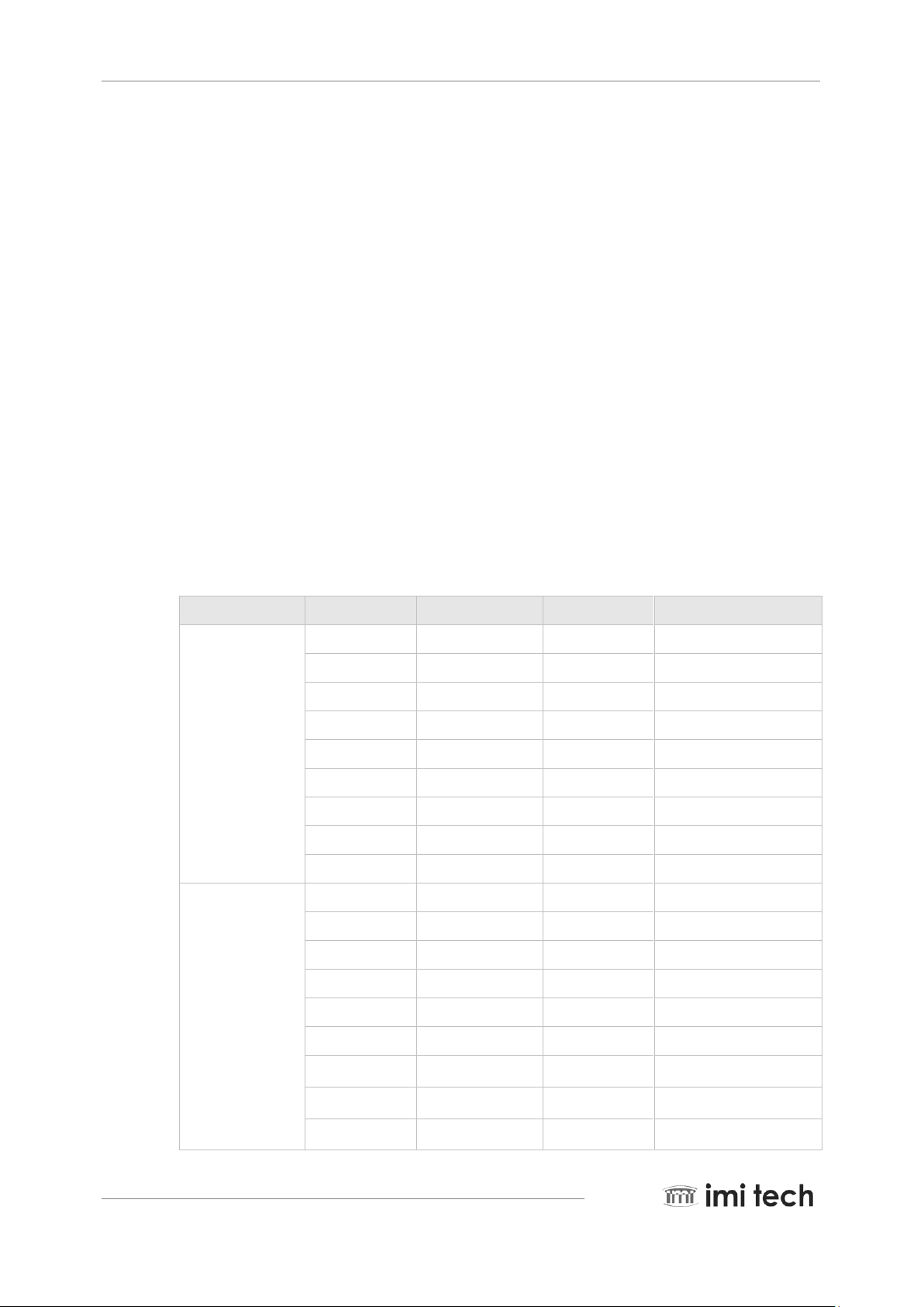
Model Name
CCD(Progressive)
Resolution
FPS at Max Resolution
Black &
White
IMB-7011G
1/3”
656 x 488
86
IMB-7012G
1/2”
656 x 484
86
IMB-7015G
1/3”
1032 x 776
34
IMB-7016G
1/3”
1288 x 964
30
IMB-7017G
1/2”
1388 x 1040
30
IMB-7018G
2/3”
1388 x 1040
30
IMB-7020G
1/1.8”
1624 x 1232
16
IMB-7020GH
1/1.8”
1624 x 1232
30
IMB-7050G
2/3”
2448 x 2048
15
Color
IMC-7011G
1/3”
652 x 484
86
IMC-7012G
1/2”
652 x 480
86
IMC -7015G
1/3”
1028 x 772
34
IMC -7016G
1/3”
1288 x 964
30
IMC -7017G
1/2”
1388 x 1040
30
IMC -7018G
2/3”
1388 x 1036
30
IMC -7020G
1/1.8”
1624 x 1232
16
IMC -7020GH
1/1.8”
1624 x 1232
30
IMC-7050G
2/3”
2448 x 2048
15
1. Introduction
1.1. Overview
IMI’s Amazon Family of cameras is compliant with the GigE Vision standard and supports Genicam Standard. Fairly
new in the image processing industry, GigE is gaining more interest thanks to users who are familiar with the
Ethernet interface and technology. This new interface is expected to lift the barriers of bandwidth limitation found in
other interfaces such as FireWire and USB 2.0. It also resolves the limitation of cable length by supporting 100
meter distance with conventional CAT-5 cable. The new GigE vision cameras are not only expected for applications
in the traditional Machine Vision applications; but its application may be stretched to intelligent traffic systems,
medical imaging, high-tech security and more. As GigE is a relatively new standard, we expect more and more
customers to demand new and additional feature support. We also expect a growing desire for software
interoperability due to GigE’s excellent network interface capability.
A large selection of cameras is available and additional cameras are scheduled to be added to the Amazon Series
as well. These will consist of various sensor sizes (1/2”, 2/3” 1/3”, 1/1.8”) and resolution (VGA, XGA, SXGA, UXGA)
both in color and black and white. The Amazon Series consist of the following models.

Page 2 AMAZON SERIES Operation Manual
Pi o n e e r i n D i g i t a l V i s i on T e c h n o l o g y
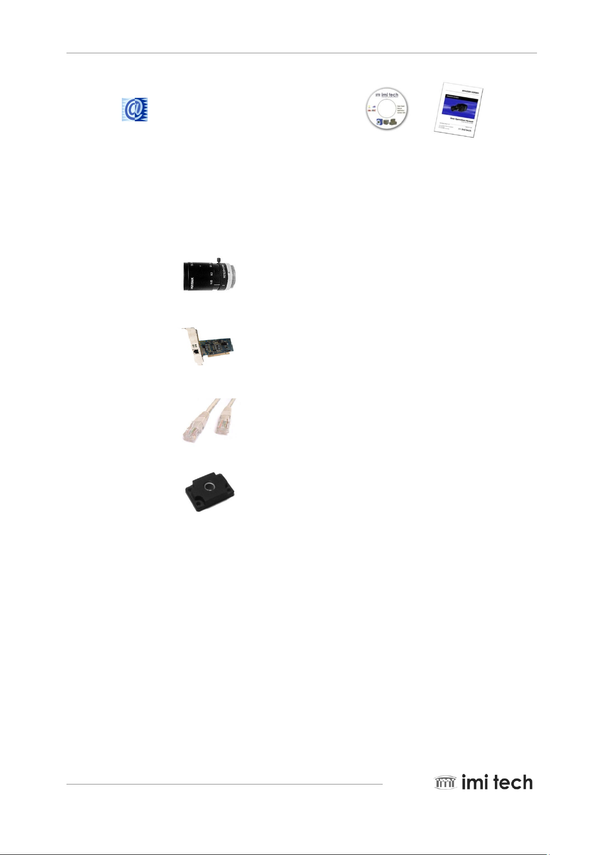
AMAZON SERIES
CAMERA UNIT
GigETM Digital Imaging CD
Driver
Demo Software
Manuals
User Manual
AMAZON SERIES’ unique features include a lookup table and external trigger mode 0, 1, 2, 4, 5 plus 12, 13, 15,
one-shot and multi-shot, a wide range of shutter speeds (1us~3600s), partial scan, and binning modes (2x2 for
B&W). All of these features provide maximum flexibility for a wide variety of applications. AMAZON SERIES
input signals are isolated optically to ensure quality images acquisition without the risk of noise degrading the input
signal. Industrial screw lock cable support has been added for more reliable connectivity. AMAZON SERIES‘s
firmware can be upgraded via GigE and the latest versions are available through our website together with IMI’s
SDK and demo applications.
1.2. Components
Component
The following components are either included in the camera or can be downloaded from the IMI website.
Downloadable Software
Latest Update of Firmware and Demo Applications are available on our website.
AMAZON SERIES Operation Manual Page 3
Pi o n e e r i n D i g i t a l V i s i on T e c h n o l o g y
http://www.imi-tech.com
Machine Vision CCD Lens
1000/100/10Mbps Gigabit PCI Adapter
GigE Cable (CAT5 , CAT6)
Tripod Plate
1.3. Optional Accessories

Page 4 AMAZON SERIES Operation Manual
Pi o n e e r i n D i g i t a l V i s i on T e c h n o l o g y
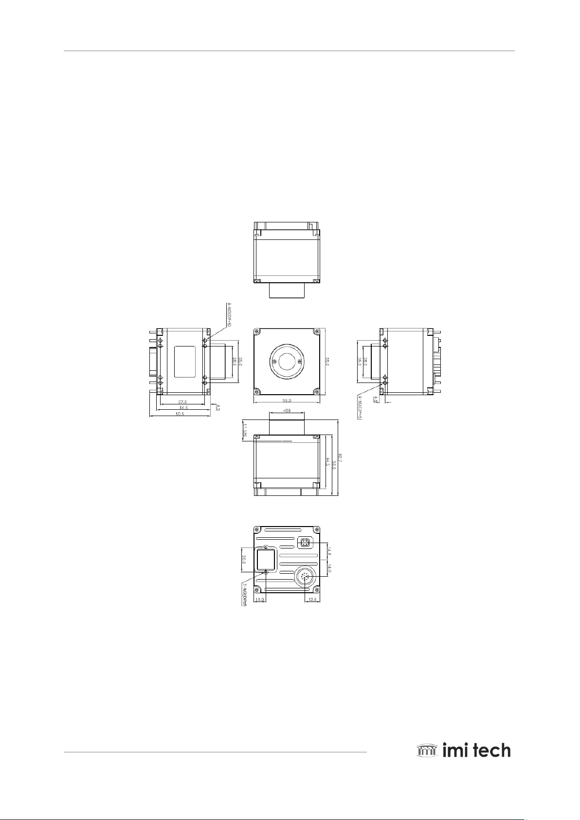
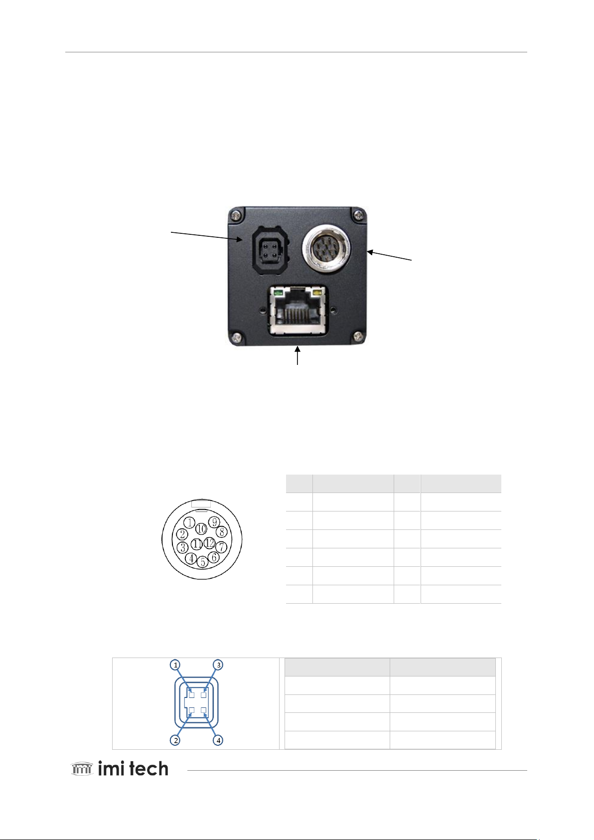
1.4. Dimension and Description
Camera Body Size : 40(w) x 40(H) x 48(D) mm
(for IMx-7011G/IMx-7012G/IMx-7015G/IMx-7016G/IMx-7017G)
Camera Body Weight: approx. 125 gram
Camera Body Size : 40(w) x 40(H) x 48(D) mm (for IMx-7018G)
Camera Body Weight : approx. 125 gram
-
AMAZON SERIES Operation Manual Page 5
Pi o n e e r i n D i g i t a l V i s i on T e c h n o l o g y
Camera Body Size : 55(w) x550(H) x 48.5(D) mm (for IMx-7020G/IMx-7020GH /IMx-7050G)
Camera Body Weight : approx. 125 gram
Page 6 AMAZON SERIES Operation Manual
Pi o n e e r i n D i g i t a l V i s i on T e c h n o l o g y
Auto Iris Lens
Control Port
Trigger/Strobe/Power
12 Pin Connector
Pin
Signal
Pin
Signal
1
POWER GND
7
GND
2
Ext Power(+12V)
8
RX RS232
3
GND
9
TX RS232
4
Ext. Trigger
10
NC
5
Ext. Trigger GND
11
Strobe 6 NC
12
Strobe Power
PIN
SIGNAL
1
Damp -
2
Damp +
3
Drive +
4
Drive -
1.5. Camera Interface
The AMAZON series camera interfaces are located on the back of the camera (assuming the lens mount is up front)
as per the following:
GigE port
1.5.1. Trigger/Strobe/Power Connector Port
The External Trigger/Strobe/Power Connector provides access to multiple I/O signals; and also provides power as a
secondary source.
Remark : NC pins must have no connection
AUTO IRIS CONNECTOR PORT

AMAZON SERIES Operation Manual Page 7
Pi o n e e r i n D i g i t a l V i s i on T e c h n o l o g y
Parameter
Min
Typical
Max I 7 mA
10 mA
20 mA
Ri
-
270Ohm
-
Vd - 1.08 V
-
Rising trigger delay
2.24 us
3.34 us
3.36 us
Falling trigger delay
2.62 us
3.61 us
3.64 us
1.5.2. Status LED
When the Yellow LED is lit, it indicates that an active network connection is available.
When the Green LED is lit, it indicates that data is being transmitted via the network connection.
Remark : When the power off, the LED is OFF
1.5.3. Camera Power Requirement
The Amazon Series cameras utilize a selection of power from the Ext. 12 pin Connector Port, which provides power
to the camera. An input voltage range of 8V ~ 30V is accepted.
1.5.4. Power Adapter connection
(-)---(O---(+)
WARNING: It is extremely important to have the core of the power adapter plug be set to plus (+). Using a
minus (-) core can damage the camera.
1.6. Electrical Operating Condition
Trigger
Strobe
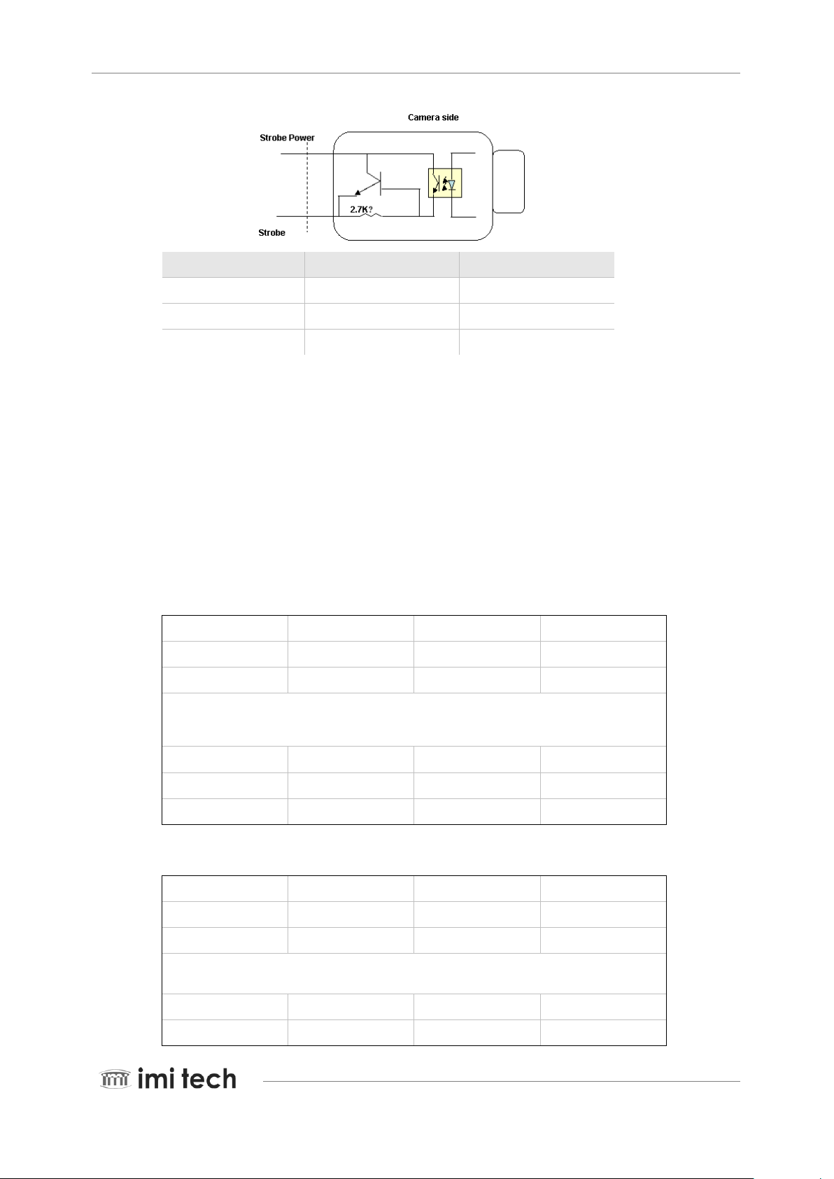
Page 8 AMAZON SERIES Operation Manual
Pi o n e e r i n D i g i t a l V i s i on T e c h n o l o g y
Strobe Power
Strobe falling delay
Strobe rising delay
5 V
26.8 us
2.16 us
12 V
7.6 us
2.8 us
24 V
3.6 us
3.4 us
U-(K+0)
Y-(K+0)
V-(K+0)
Y-(K+1)
U-(K+2)
Y-(K+2)
V-(K+2)
Y-(K+3)
U-(K+4)
Y-(K+4)
V-(K+4)
Y-(K+5)
U-(K+Pn-6)
Y-(K+Pn-6)
V-(K+Pn-6)
Y-(K+Pn-5)
U-(K+Pn-4)
Y-(K+Pn-4)
V-(K+Pn-4)
Y-(K+Pn-3)
U-(K+Pn-2)
Y-(K+Pn-2)
V-(K+Pn-2)
Y-(K+Pn-1)
U-(K+0)
Y-(K+0)
Y-(K+1)
V-(K+0)
Y-(K+2)
Y-(K+3)
U-(K+4)
Y-(K+4)
Y-(K+5)
V-(K+4)
V-(K+4)
Y-(K+5)
U-(K+Pn-8)
Y-(K+Pn-8)
Y-(K+Pn-7)
V-(K+Pn-8)
Y-(K+Pn-6)
Y-(K+Pn-5)
U-(K+Pn-4)
Y-(K+Pn-4)
1.7. Pixel Data
The AMAZON series complies with the AIA GigE Vision version 1.0 where data packets are transmitted by a Gigabit
Ethernet interface.
<YUV (4: 2: 2) format >
<YUV (4: 1: 1) format >

AMAZON SERIES Operation Manual Page 9
Pi o n e e r i n D i g i t a l V i s i on T e c h n o l o g y
Y-(K+Pn-3)
V-(K+Pn-4)
Y-(K+Pn-2)
Y-(K+Pn-1)
Y-(K+0)
Y-(K+1)
Y-(K+2)
Y-(K+3)
Y-(K+4)
Y-(K+5)
Y-(K+6)
Y-(K+7)
Y-(K+Pn-8)
Y-(K+Pn-7)
Y-(K+Pn-6)
Y-(K+Pn-5)
Y-(K+Pn-4)
V-(K+Pn-3)
Y-(K+Pn-2)
Y-(K+Pn-1)
High Byte
Low Byte Y-(K+0)
Y-(K+1)
Y-(K+2)
Y-(K+3)
Y-(K+Pn-4)
Y-(K+Pn-3)
V-(K+Pn-2)
Y-(K+Pn-1)
Signal Level (Decimal)
Data (Hexadecimal)
Highest
255
0xFF 254
0xFE
. . .
.
1
0x01
Lowest
0
0x00
Signal Level (Decimal)
Data (Hexadecimal)
Highest(+)
127
0xFF 126
0xFE
. . .
.
<Mono 8/GR8 Format>
<Mono 12/ GR12 Format>
Data Structure
<Y, R, G, B>
Each component has 8 bits of data. The data type is “Unsigned Char”
<U, V>
Each component has 8 bits of data. The data type is “Straight Binary”

Page 10 AMAZON SERIES Operation Manual
Pi o n e e r i n D i g i t a l V i s i on T e c h n o l o g y
1
0x81
Lowest
0
0x80 -1
0x7F
. . .
. -127
0x01
Lowest
-128
0x00
Y
Signal Level (Decimal)
Data (Hexadecimal)
Highest
65535
0xFFFF
65534
0xFFFE
. . .
. 1
0x0001
Lowest
0
0x0000
<Y(Mono16)>
Y component has 16 bits of data. The data type is “Unsigned Short (big-endian)”
1.8. Environmental Requirements.
Operation Temperature: -5°C ~ +45°C / Storage Temperature: -30°C ~ +65°C
Avoid operation in an environment of high humidity of over 90% and allow sufficient airflow for prevention of heat
buildup

AMAZON SERIES Operation Manual Page 11
Pi o n e e r i n D i g i t a l V i s i on T e c h n o l o g y
Requirements
Details and Description
Operating System
Windows XP, Window 7
CPU
Intel Core2quad or better spec
System Memory
2GB or more
Video Adapter
1280 x 1024 with 24 bit color or higher
Hard Disk Drive
40 GB or higher
Optical Drive
CDROM or DVDROM
Gigabit Ethernet Interface
On
Cable
Standard Gigabit Ethernet Cable (RJ45)
Power Supply
DC 8V ~ 30V.
Software
DirectX 9.0 or higher, IMI Tech Digital Imaging CD
Basic
Hardware Installation
and
Camera Connection
2. Basic Installation
The Amazon series operates in connection with a PC that is running an operation system such as MS Windows.
Basic installation starts by installing the driver, connecting the camera and loading the demo application software.
Please refer to the demo application software manual for details.
2.1. Recommended System Requirement
Remark: Other software or hardware may be required for user specific applications.
2.2. Hardware Installation
Basic camera installation is a very simple 3 step process as follows. ( Also check the figure below. )
Step 1. Locate the Gigabit Ethernet port on the computer.
(Note : Some computers would require the installation of a PCI/ PCI express Gigabit Ethernet interface. ).
Step 2. Plug one end of the GigE cable into the camera; and the other end of the cable into the computer’s Gigabit
Ethernet port.
Page 12 AMAZON SERIES Operation Manual
Pi o n e e r i n D i g i t a l V i s i on T e c h n o l o g y
IMI Digital Imaging CD(WebSite)
Driver
Neptune Demo Software
Neptune API Library
Manuals(Website)
2.3. Software Installation
Important! DO NOT CONNECT THE CAMERA BEFORE INSTALLING THE SOFTWARE!!
Insert the IMI Digital Imaging CD which would auto install the camera drivers and demo applications.
Or download the camera drivers and demo applications from the IMI website at www.imi-tech.com.
( For details of the application and driver please refer to the demo application manual.)
NOTE: Software Installation should proceed Hardware Installation
AMAZON SERIES Operation Manual Page 13
Pi o n e e r i n D i g i t a l V i s i on T e c h n o l o g y
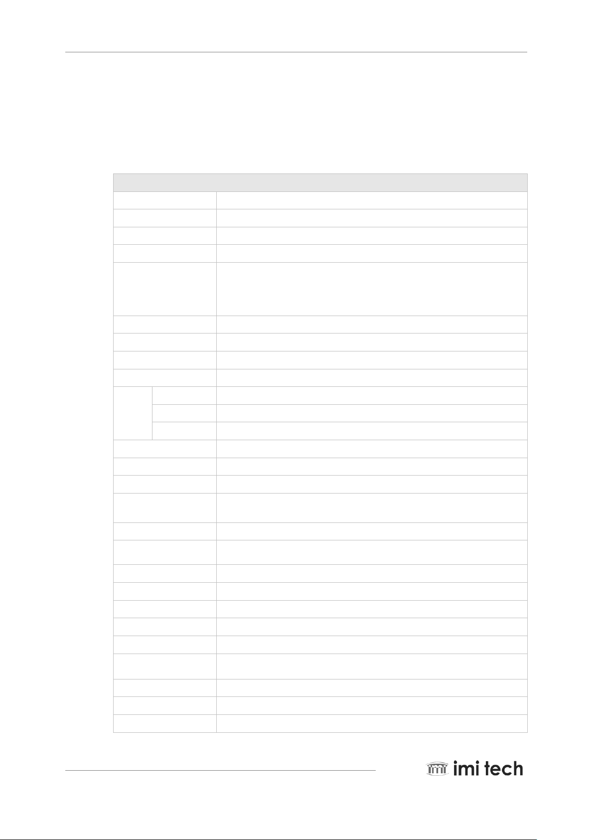
Features
Image Sensor Type
2/3-inch Interline CCD (ICX625ALA)
Effective pixels
5,054,448 pixels 2456(H) x 2058(V)
Picture Size
2448x2048
Cell Size(um)
3.45x3.45
Real Frame Rate
15 (2448x2048 mono 8)
7.5 (2448x2048 mono 12)
27 (1220x1020 mono 8, 2x2 Binning)
13.5 (1220x1020 mono 12, 2x2 Binning)
Lens Mount
C-Mount
Lens Support
DC Auto IRIS Lens
Scanning System
Progressive System
Binning
2x2
Trigger
Edge
Rising Edge or Falling Edge
Mode
0, 1, 2, 4, 5,12,13 15
Source
External Trigger or Software Trigger
Strobe
Support Normal Mode or Trigger Mode.
Memory Save/Load
9 Channels (0:factory, 1~4:feature, 5~8:mode/feature)
One-shot/Multi-shot
65535 Shots
Control Functions
Brightness, Sharpness, Gamma, Auto-Exposure, Shutter, Gain
User Defined LUT, Auto IRIS Lens
SIO(RS-232)
Path through or IMI-Tech Command
Digital Interface /
Transfer Rate
1000BT, RJ45 / 1Gbps
Gain
0 ~ 18 dB
Shutter Speed
5 usec ~ 3600 sec
Data Depth
12 bit B/W
Supply Voltage
8VDC~30VDC
Power
5.0 [W] (DC12V, 410mA)
External Dimension /
Weight
TBD
Operation Temp.
-5°C to 45°C
Storage Temp
-30°C to 60°C
Camera Specification
AIA GigE Vision version 1.0
3. AMAZON Series Camera Specifications.
3.1. Black and White Camera
3.1.1. IMB-7050G Specification

Page 14 AMAZON SERIES Operation Manual
Pi o n e e r i n D i g i t a l V i s i on T e c h n o l o g y
Features (IMB-7020GH)
Image Sensor
1/1.8” Interline CCD(ICX274AL)
Effective Pixels
2,012,208 pixels 1628(H) x 1236(V)
Picture Size
1600x1200
Cell Size
4.4 um x 4.4 um
Real Frame Rate
30 (1600x1200, Mono 8)
15 (1600x1200, Mono 12_Not support Jumbo packet)
Not Support (800x600, 2x2 binning, Mono 8)
Not Support (800x600, 2x2 binning, Mono 12)
Lens Mount
C-mount, CS-Mount
Scanning System
Progressive System
Binning
Not Support
Partial Scan
(Unit: 4x4)
Trigger
Edge
Rising Edge or Falling Edge
Mode
0, 1, 2, 4, 5, 12, 13, 15
Source
External Trigger(Photo-coupler) or Software Trigger
Strobe 1, 2
Support Normal Mode or Trigger Mode. (Photo-coupler)
Memory Save/Load
9 Channels(0:factory, 1~4:feature, 5~8:mode/feature)
One-shot/Multi-shot
1 Shots ~ 65535 Shots
Control Functions
Brightness, Sharpness, Gamma, Auto-Exposure, Shutter, Gain,
User Defined LUT, Auto-Iris Control
SIO(RS-232)
Path through or IMI-Tech Command
Digital Interface / Transfer Rate
1000BT, RJ45 / 1Gbps
Gain
0 ~ 18 dB (Manual or Auto control)
Shutter Speed
1 usec ~ 3600 sec (Manual or Auto control)
Data Depth
12 bit
S/N Ratio
56dB or better
Supply Voltage& Power
Less than 3 Watts (@12V DC)
External Dimension / Weight
55(W) x 55(H) x 50.5(D) mm / Approx 200g
Operation Temp/ Storage Temp
-5°C to 45°C / -30°C to 60°C
Camera Specification
AIA GigE Vision version 1.0
3.1.2. IMB-7020GH Specification
Remark: Camera specification described above may be changed without notice

AMAZON SERIES Operation Manual Page 15
Pi o n e e r i n D i g i t a l V i s i on T e c h n o l o g y
Features (IMB-7020G)
Image Sensor
1/1.8” Interline CCD(ICX274AL)
Effective Pixels
2,012,208 pixels 1628(H) x 1236(V)
Picture Size
1624x1232
Cell Size
4.4 um x 4.4 um
Real Frame Rate
16 (1624x1232, Mono 8)
8 (1624x1232, Mono 12)
30 (800x600, 2x2 binning, Mono 8)
15 (800x600, 2x2 binning, Mono 12)
Lens Mount
C-mount, CS-Mount
Scanning System
Progressive System
Binning
2x2
Partial Scan
(Unit: 4x4)
Trigger
Edge
Rising Edge or Falling Edge
Mode
0, 1, 2, 4, 5, 12, 13, 15
Source
External Trigger(Photo-coupler) or Software Trigger
Strobe
Support Normal Mode or Trigger Mode. (Photo-coupler)
Memory Save/Load
9 Channels(0:factory, 1~4:feature, 5~8:mode/feature)
One-shot/Multi-shot
1 Shots ~ 65535 Shots
Control Functions
Brightness, Sharpness, Gamma, Auto-Exposure, Shutter, Gain,
User Defined LUT, Auto-Iris Control
SIO(RS-232)
Path through or IMI-Tech Command
Digital Interface / Transfer Rate
1000BT, RJ45 / 1Gbps
Gain
0 ~ 18 dB (Manual or Auto control)
Shutter Speed
1 usec ~ 3600 sec (Manual or Auto control)
Data Depth
12 bit
S/N Ratio
56dB or better
Supply Voltage& Power
Less than 3 Watts (@12V DC)
External Dimension / Weight
40(W) x 40(H) x 48(D) mm / Approx 125g
Operation Temp/ Storage Temp
-5°C to 45°C / -30°C to 60°C
Camera Specification
AIA GigE Vision version 1.0
3.1.3. IMB-7020G Specification
Remark: Camera specification described above may be changed without notice

Page 16 AMAZON SERIES Operation Manual
Pi o n e e r i n D i g i t a l V i s i on T e c h n o l o g y
Features (IMB-7018G)
Image Sensor
2/3” Interline CCD(ICX285AL)
Effective Pixels
1,447,680 pixels 1392(H) x 1040(V)
Picture Size
1388x1040
Cell Size
6.45um x 6.45 um
Real Frame Rate
31 (1388x1040, Mono 8)
15 (1388x1040,Mono 12)
56 (688x516, 2x2 binning, Mono 8)
28 (688x516, 2x2 binning, Mono 12)
Lens Mount
C-mount, CS-Mount
Scanning System
Progressive System
Binning
2x2
Partial Scan
(Unit: 4x4)
Trigger
Edge
Rising Edge or Falling Edge
Mode
0, 1, 2, 4, 5, 12,13,15
Source
External Trigger (Photo-coupler) or Software Trigger
Strobe
Support Normal Mode or Trigger Mode. (Photo-coupler)
Memory Save/Load
9 Channels (0:factory, 1~4:feature, 5~8:mode/feature)
One-shot/Multi-shot
1 Shots ~ 65535 Shots
Control Functions
Brightness, Sharpness, Gamma, Auto-Exposure, Shutter, Gain,
User Defined LUT, Auto-Iris Control
SIO(RS-232)
Path through or IMI-Tech Command
Digital Interface / Transfer Rate
1000BT, RJ45 / 1Gbps
Gain
0 ~ 18 dB(Manual or Auto control)
Shutter Speed
1 usec ~ 3600 sec (Manual or Auto control)
Data Depth
12 bit
S/N Ratio
56dB or better
Supply Voltage& Power
Less than 3 Watts (@12V DC)
External Dimension / Weight
44(W) x 40(H) x 48(D) mm / Approx 125g
Operation Temp. / Storage Temp.
-5°C to 45°C / -30°C to 60°C
Camera Specification
AIA GigE Vision version 1.0
3.1.4. IMB-7018G Specification
Remark: Camera specification described above may be changed without notice

AMAZON SERIES Operation Manual Page 17
Pi o n e e r i n D i g i t a l V i s i on T e c h n o l o g y
Features (IMB-7017G)
Image Sensor
1/2” Interline CCD(ICX267AL)
Effective Pixels
1,447,680 pixels 1392(H) x 1040(V)
Picture Size
1388x1040
Cell Size
4.65 um x 4.65 um
Real Frame Rate
31 (1388x1040, Mono 8)
15 (1388x1040,Mono 12)
58 (688x516, 2x2 binning, Mono 8)
29 (688x516, 2x2 binning, Mono 12)
Lens Mount
C-mount, CS-Mount
Scanning System
Progressive System
Binning
2x2
Partial Scan
(Unit: 4x4)
Trigger
Edge
Rising Edge or Falling Edge
Mode
0, 1, 2, 4, 5, 12, 13, 15
Source
External Trigger (Photo-coupler) or Software Trigger
Strobe
Support Normal Mode or Trigger Mode. (Photo-coupler)
Memory Save/Load
9 Channels (0:factory, 1~4:feature, 5~8:mode/feature)
One-shot/Multi-shot
1 Shots ~ 65535 Shots
Control Functions
Brightness, Sharpness, Gamma, Auto-Exposure, Shutter, Gain,
User Defined LUT, Auto-Iris Control
SIO(RS-232)
Path through or IMI-Tech Command
Digital Interface / Transfer Rate
1000BT, RJ45/ 1Gbps
Gain
0 ~ 18 dB(Manual or Auto control)
Shutter Speed
1 usec ~ 3600 sec (Manual or Auto control)
Data Depth
12 bit
S/N Ratio
56dB or better
Supply Voltage& Power
Less than 3 Watts (@12V DC)
External Dimension / Weight
44(W) x 40(H) x 48(D) mm / Approx 125g
Operation Temp. / Storage Temp.
-5°C to 45°C / -30°C to 60°C
Camera Specification
AIA GigE Vision version 1.0
3.1.5. IMB-7017G Specification
Remark: Camera specification described above may be changed without notice

Page 18 AMAZON SERIES Operation Manual
Pi o n e e r i n D i g i t a l V i s i on T e c h n o l o g y
Features( IMB-7016G)
Image Sensor Type
1/3” Interline CCD (ICX445AL)
Effective pixels
1,251,936 pixels 1296(H) x 966(V)
Picture Size
1288 x 964
Cell Size(um)
3.75 um x3.75 um
Real Frame Rate
30 (1288x964, Mono 8)
15 (1288x964,Mono 12)
55 (640X476, 2x2 binning, Mono 8)
27 (640X476, 2x2 binning, Mono 12)
Lens Mount
C-mount, CS-Mount
Scanning System
Progressive System
Binning
2x2
Partial Scan
(Unit: 4x4)
Trigger
Edge
Rising Edge or Falling Edge
Mode
0, 1, 2, 4, 5, 12, 13, 15
Source
External Trigger (Photo-coupler) or Software Trigger
Strobe
Support Normal Mode or Trigger Mode. (Photo-coupler)
Memory Save/Load
9 Channels (0:factory, 1~4:feature, 5~8:mode/feature)
One-shot/Multi-shot
1 shot ~ 65535 Shots
Control Functions
Brightness, Sharpness, Gamma, Auto-Exposure, Shutter, Gain,
User Defined LUT, Auto-Iris Control
SIO(RS-232)
Path through or IMI-Tech Command
Digital Interface / Transfer Rate
1000BT, RJ45 / 1Gbps
Gain
0 ~ 18 dB(Manual or Auto control)
Shutter Speed
1 usec ~ 3600 sec(Manual or Auto control)
Data Depth
12 bit
S/N Ratio
56dB or better
Supply Voltage& Power
Less than 3 Watts (@12V DC)
External Dimension / Weight
40(W) x 40(H) x 48(D) mm / Approx 125g
Operation Temp. / Storage Temp.
-5°C to 45°C / -30°C to 60°C
Camera Specification
AIA GigE Vision version 1.0
3.1.6. IMB-7016G Specification
Remark: Camera specification described above may be changed without notice

AMAZON SERIES Operation Manual Page 19
Pi o n e e r i n D i g i t a l V i s i on T e c h n o l o g y
Features(IMB-7015G)
Image Sensor Type
1/3” Interline CCD (ICX204AL)
Effective pixels
805,486 pixels 1034(H) x 779(V)
Picture Size
1032 x 776
Cell Size(um)
4.65 um x4.65 um
Real Frame Rate
36 (1032x776, Mono 8)
18 (1032x776,Mono 12)
65 (512x384, 2x2 binning, Mono 8)
33 (512x384, 2x2 binning, Mono 12)
Lens Mount
C-mount, CS-Mount
Scanning System
Progressive System
Binning
2x2
Partial Scan
(Unit: 4x4)
Trigger
Edge
Rising Edge or Falling Edge
Mode
0, 1, 2, 4, 5, 12, 13, 15
Source
External Trigger (Photo-coupler) or Software Trigger
Strobe
Support Normal Mode or Trigger Mode. (Photo-coupler)
Memory Save/Load
9 Channels (0:factory, 1~4:feature, 5~8:mode/feature)
One-shot/Multi-shot
1 shot ~ 65535 Shots
Control Functions
Brightness, Sharpness, Gamma, Auto-Exposure, Shutter, Gain,
User Defined LUT, Auto-Iris Control
SIO(RS-232)
Path through or IMI-Tech Command
Digital Interface / Transfer Rate
1000BT, RJ45 / 1Gbps
Gain
0 ~ 18 dB(Manual or Auto control)
Shutter Speed
1 usec ~ 3600 sec(Manual or Auto control)
Data Depth
12 bit
S/N Ratio
56dB or better
Supply Voltage& Power
Less than 3 Watts (@12V DC)
External Dimension / Weight
40(W) x 40(H) x 48(D) mm / Approx 125g
Operation Temp. / Storage Temp.
-5°C to 45°C / -30°C to 60°C
Camera Specification
AIA GigE Vision version 1.0
3.1.7. IMB-7015G Specification
Remark: Camera specification described above may be changed without notice
 Loading...