

Imi Tech IMB-17FT, IMB-12FT, IMB-11FT, IMB-13FC, IMB-16FC User's Operation Manual
...
PEARL SERIES
PEARL SERIES
Tiny Form Factor
User Operation Manual
FIREWIRE CCD & CMOS Cameras
USER MANUAL VERSION 2.0
Released September 2009
#2 Eun-Seok Bldg. 729-1 Yeoksam-Dong, Gangnam-Gu
Seoul 135-080, Korea
Tel : 82-2-527-9800 Fax : 82-2-527-9900

Legal Notice.
For Customers in U.S.A.
This equipment has been tested and found to comply with the limits for a Class B digital device, pursuant to Part 15 of the FCC
Rules. These limits are designed to provide reasonable protection against harmful interference when the equipment is
operated in a commercial environment. This equipment generates, uses, and can radiate radio frequency energy and, if not
installed and used in accordance with the instruction manual, may cause harmful interference to radio communications.
Operation of this equipment in a residential area is likely to cause harmful interference in which case the user will be required to
correct the interference at own expense. You are cautioned that any changes or modifications not expressly approved in this
manual could void your authority to operate this equipment. The shielded interface cable recommended in this manual must
be used with this equipment in order to comply with the limits for a computing device pursuant to Subpart J of Part 15 of FCC
Rules.
For customers in Europe
This apparatus has been certified to meet or exceed the standards for CE compliance per the Council Directives. Pertinent
testing documentation is available for verification.
For customers in Canada
This apparatus complies with the Class B limits for radio noise emissions set out in the Radio Interference Regulations.
Pour utilisateurs au Canada
Cet appareil est conforme aux normes Classe B pour bruits radioélectriques, spécifiées dans le Règlement sur le brouillage
radioélectrique.
Life support applications
These products are not designed for use in life support appliances, devices, or systems where malfunction of these products can
reasonably be expected to result in personal injury. Allied customers using or selling these products for use in such
applications do so at their own risk and agree to fully indemnify allied for any damages resulting from such improper use or sale.

Before You Start
This manual should help you in the installation and setting up of the camera; and we recommend that you carefully follow the
instructions described. To ensure that your warranty remains valid, please read the manual carefully before using the camera.
DO NOT disassemble, modify or repair the camera. There is no user serviceable part inside and disassembling the camera may
void the warranty. For prevention of fire or electric shock, DO NOT remove screws or covers from the camera.
Operation in a wet environment is NOT recommended and the camera SHOULD NOT be exposed to rain or moisture.
For prolong life and the protection of the camera’s CCD, do not point the camera directly at the sun or a strong spotlight which
may result in CCD blooming and permanent damage.
DO NOT operate the camera beyond the operation temperature range stated and AVOID usage in conditions exceeding 90%
humidity.
DO NOT use an unregulated power supply source to prevent damage to the camera’s circuits.
Use soft materials such as lens tissue or a cotton tipped applicator with ethanol for CCD faceplate cleaning ONLY when
necessary and AVOID contact with fingers or any hard object. Do not use solvent, abrasives or detergent when cleaning the
camera body.
Warranty shall be voided for improper use of the camera or fault caused by the user or damage caused by other equipment due
to negligence
Warranty
IMI TECH warrants the original components free of defects for one year from purchase date. This warranty covers failures and
damage due to defect, which may occur during normal use. It does not cover damages or failure resulting from mishandling,
abuse, misuse or modification. An RMA number must be obtained in advance for every repair or replacement.
Disclaimer
The information in this document has been carefully checked and is believed to be reliable. However, IMI TECH assumes no
responsibility for inaccuracies. There is no legal obligation to document internal relationships in any functional module of its
products, in either hardware or software.
Copyright
All the materials in this document are protected by copyright and other laws for intellectual property. They are not allowed to
be copied, reproduced or modified for any use without the permission of IMI Tech. IMI TECH reserves the right to make
changes in specifications, functions or designs at any time and without any notice. The company names in this document may
be the trademarks and trade-names of their respective owner; and are hereby acknowledged.
Copyright © 2005 IMI TECHNOLOGY CO.,LTD. All rights reserved.

Pearl Series Operation Manual
1. Introduction .................................................................................................................. 1
1.1. Overview ............................................................................................................................................................... 1
1.2. Components .......................................................................................................................................................... 2
1.3. Optional Accessories ............................................................................................................................................... 3
1.4. Dimension and Description ..................................................................................................................................... 4
1.5. Camera Interface ................................................................................................................................................... 4
1.6. FIREWIRE Port .................................................................................................................................................... 5
1.6.1. Trigger Connector Port .................................................................................................................................. 5
1.6.2. Status LED ................................................................................................................................................... 6
1.7. Electrical Operating Condition ................................................................................................................................. 6
1.8. Pixel Data .............................................................................................................................................................. 7
1.9. Environmental Requirements ................................................................................................................................ 10
2. Basic Installation ........................................................................................................ 11
2.1. Recommended System Requirement ..................................................................................................................... 11
2.2. Hardware Installation ........................................................................................................................................... 11
2.3. Software Installation ............................................................................................................................................ 12
3. PEARL Series Camera Specifications .......................................................................... 13
3.1. Black and White Camera ....................................................................................................................................... 13
3.1.1. IMB-20FT Specification ............................................................................................................................... 13
3.1.2. IMB-17FT Specification ............................................................................................................................. 14
3.1.3. IMB-16FT Specification ............................................................................................................................... 15
3.1.4. IMB-15FT Specification ............................................................................................................................... 16
3.1.5. IMB-12FT Specification ............................................................................................................................. 17
3.1.6. IMB-11FT Specification ............................................................................................................................. 18
3.1.7. IMB-16FC Specification ............................................................................................................................. 19
3.1.8. IMB-13FC Specification ............................................................................................................................... 20
3.2. Color Cameras ..................................................................................................................................................... 21
3.2.1. IMC-20FT Specification ............................................................................................................................. 21

3.2.2.
IMC-17FT Specification ............................................................................................................................. 22
3.2.3. IMC-16FT Specification ............................................................................................................................. 23
3.2.4. IMC-15FT Specification ............................................................................................................................. 24
3.2.5. IMC-12FT Specification (Preliminary) ......................................................................................................... 25
3.2.6. IMC-11FT Specification ............................................................................................................................. 26
3.2.7. IMC-30FC Specification ............................................................................................................................. 27
3.2.8. IMC-13FC Specification ............................................................................................................................. 28
3.3. Spectral Sensitivity ............................................................................................................................................... 29
3.3.1. Pearl Series B&W Cameras .......................................................................................................................... 29
3.3.2. Pearl Series Color Cameras .......................................................................................................................... 33
4. Basic Operation and Features ..................................................................................... 38
4.1. Brightness ........................................................................................................................................................... 38
4.2. Auto Exposure Control .......................................................................................................................................... 39
4.3. Sharpness ............................................................................................................................................................ 40
4.4. White Balance ...................................................................................................................................................... 40
4.5. Hue ..................................................................................................................................................................... 41
4.6. Gamma ............................................................................................................................................................... 41
4.7. Shutter ................................................................................................................................................................ 42
4.7.1. IMx-xxFT .................................................................................................................................................... 42
4.7.2. IMx-xxFC .................................................................................................................................................... 43
4.8. Gain .................................................................................................................................................................... 44
4.8.1. IMx-xxFT .................................................................................................................................................... 44
4.8.2. IMx-xxFC .................................................................................................................................................... 44
4.9. Trigger & Strobe................................................................................................................................................... 44
4.9.1. Supported Trigger ....................................................................................................................................... 44
4.9.1.1. IMx-xxFT .............................................................................................................................................................................. 44
4.9.1.2. IMX-xxFC ............................................................................................................................................................................. 45
4.9.2. Trigger and Strobe Signal Relation ............................................................................................................... 46
4.9.2.1. IMx-xxFT .............................................................................................................................................................................. 46
4.9.2.2. IMx-xxFC .............................................................................................................................................................................. 47
4.9.2.3. Trigger Timing Diagram for IMx-xxFC................................................................................................................................ 48
4.9.3. Timing Diagram for External Trigger and Shutter and Strobe ......................................................................... 49
4.9.3.1. IMx-xxFT .............................................................................................................................................................................. 49

4.9.4.
Trigger & Strobe delay ................................................................................................................................. 49
4.9.5. Trigger Mode 0 ........................................................................................................................................... 50
4.9.6. Trigger Mode 1 ........................................................................................................................................... 50
4.9.7. Trigger Mode 2 ........................................................................................................................................... 50
4.9.8. Trigger Mode 3 ........................................................................................................................................... 51
4.9.9. Trigger Mode 4 ........................................................................................................................................... 51
4.9.10. Trigger Mode 5 ........................................................................................................................................... 52
4.9.11. Trigger Mode 14.......................................................................................................................................... 52
4.9.12. Trigger Mode 15.......................................................................................................................................... 52
4.10. Strobe Control Register ..................................................................................................................................... 54
4.11. Trigger Delay Control ........................................................................................................................................ 55
4.11.1. Strobe Delay and Duration Table .................................................................................................................. 56
4.12. Optical Filter Control ......................................................................................................................................... 56
4.13. Color (Bayer) Patterns Conversion ...................................................................................................................... 57
5. Advanced Features ..................................................................................................... 58
5.1. Binning Mode ....................................................................................................................................................... 58
5.1.1. Vertical Binning ........................................................................................................................................... 58
5.1.2. Horizontal Binning ....................................................................................................................................... 58
5.1.3. Full Binning ................................................................................................................................................ 59
5.2. Partial Scan ......................................................................................................................................................... 59
5.2.1. Pan/Tilt ...................................................................................................................................................... 60
5.3. One-Shot and Multi-Shot ...................................................................................................................................... 60
5.4. Multi-Camera Auto-sync. ....................................................................................................................................... 61
5.5. Asynchronous Broadcasting .................................................................................................................................. 61
5.6. Memory Channel Save / Load ................................................................................................................................ 62
5.7. Time Stamp Register ............................................................................................................................................ 62
5.8. Serial Interface .................................................................................................................................................... 63
5.8.1. SIO Pass Through Scheme .......................................................................................................................... 63
5.8.2. SIO (RS232) Control Setting Procedure ........................................................................................................ 63
5.8.3. SIO (RS232) RX Control Procedure ............................................................................................................... 64
5.8.4. SIO (RS232) TX Control Procedure Method I ................................................................................................ 65
5.8.5. SIO (RS232) TX Control Procedure Method II ............................................................................................... 66

5.8.6.
SIO(RS232) Registers .................................................................................................................................. 67
5.8.7. SIO(RS232) IMI TECH Commands ............................................................................................................. 70
5.9. Frame Save Function ............................................................................................................................................ 71
5.10. LUT(Lookup table) ............................................................................................................................................ 72
5.10.1. 4-step knee lookup table ............................................................................................................................. 72
5.10.2. User defined lookup table ............................................................................................................................ 73
5.11. One Pixel Snow Noise Remove ........................................................................................................................... 74
5.11.1. PIO Control Register ................................................................................................................................... 76
5.12. Edge Enhancement ........................................................................................................................................... 76
6. User Defined FIREWIRE Registers ............................................................................. 77
6.1. User Defined FIREWIRE Address ........................................................................................................................... 77
7. Video Formats and Modes ........................................................................................... 81
7.1 . IMB-20FT / IMC-20FT ........................................................................................................................................... 82
7.2 . IMB-17FT / IMC-17FT ........................................................................................................................................... 82
7.3 . IMB-15FT / IMC-15FT ........................................................................................................................................... 83
7.4 . IMB-12FT / IMC-12FT ........................................................................................................................................... 84
7.5 . IMB-11FT / IMC-11FT ........................................................................................................................................... 84
7.6 . IMC-30FC ............................................................................................................................................................ 85
7.7. IMB-16FC ............................................................................................................................................................ 85
7.8 . IMB-13FC / IMC-13FC ........................................................................................................................................... 86
7.9 . Trouble Shooting .................................................................................................................................................. 87
7.10. Hardware Related Issues ................................................................................................................................... 87
7.10.1. Camera is not recognized in the device manager .......................................................................................... 87
7.10.2. LED is OFF while power is provided either by FireWire or external power. ....................................................... 87
7.10.3. No Image or Black Image is Displayed ......................................................................................................... 87
7.11. Software Related Issues .................................................................................................................................... 88
7.11.1. System Environment ................................................................................................................................... 88
7.11.2. Appears in Device Manager as unknown device ............................................................................................ 88
7.11.3. Multiple Camera Connection ........................................................................................................................ 88
7.11.4. IMI’s Driver Support .................................................................................................................................... 88

7.11.5.
Camera Supported Frame Rate cannot be achieved. ..................................................................................... 88
7.11.6. How to read the serial number..................................................................................................................... 88
8. Revision History .......................................................................................................... 89
8.1. Added Since V 1.0 ................................................................................................................................................ 89
9. Firmware Update ........................................................................................................ 89
10. Technical Support ....................................................................................................... 89
PEARL SERIES Operation Manual Page 1
Pioneer in Digital Vision Technology
1. Introduction
1.1. Overview
IMI Tech’s PEARL Series opens up a new horizon in digital image processing; by providing more features in a very
small form factor while still maintaining excellent cost effectiveness and high quality. The Pearl Series models
are comprised of a wide range of resolutions and are equipped with a FIREWIRE
TM
interface and a trigger to suit the
needs of every application. The Pearl Series offers the highest frame rate in each of its resolutions compared
with other products currently available. The very small form factor design has expanded implementation and
broadened application areas by eliminating the limits that currently exist due to size and weight. A large selection
of cameras is available in the PEARL SERIES which consist of sensors sizes(1/3”, 1/2”, 1/1.8”) and resolution(VGA,
XGA, SXGA, UXGA) both in color and black & white. The PEARL SERIES consist of the following models, which
have either CCD sensors or CMOS sensors.
I
M
I
T
e
c
h
’
s
n
e
w
P
E
T
T
h
The PEARL Series IMx-xxFT cameras with CCD sensors possess unique features that support external trigger mode
0~5 plus 14,15, multi camera auto-sync, one-shot and multi-shot, a wide range of shutter speed, RS232C pass
through via FIREWIRE
TM
, Fast format 7, partial scan, and a high speed up trigger frame rate, which would provide
maximum flexibility in applications. An Industrial Screw Lock cable support has been added for more reliable
PEARL Series
Model Name CCD(xxFT) CMOS(xxFC) Resolution
FPS at Max
Res.
Black &
White
IMB-20FT 1/1.8” 1600 x 1200 16
IMB-17FT 1/2” 1388 x 1040 20
IMB-16FT 1/3” 1292 x 960 25
IMB-15FT 1/3” 1024 x 768 36
IMB-12FT 1/2” 640 x 480 86
IMB-11FT 1/3” 640 x 480 86
IMB-13FC 1/3” 752 x 480 60
IMB-16FC 1/2” 1280 x 1024 24
Color
IMC-20FT 1/1.8” 1600x1200 16
IMC-17FT 1/2” 1388x1036 20
IMC-16FT 1/3” 1292 x 960 25
IMC-15FT 1/3” 1024 x 768 36
IMC-12FT 1/2” 640 x 480 86
IMC-11FT 1/3” 640 x 480 86
IMC-13FC 1/3” 752 x 480 60
IMC-30FC 1/2” 2048 x 1536 10
Page 2 PEARL SERIES Operation Manual
connectivity. The PEARL SERIES firmware can be upgraded via FIREWIRE
TM
and the latest versions are
available through our website; together with IMI’s SDK and demo applications. The PEARL SERIES IMx-xxFC
cameras with CMOS sensors possess the same features and support the same functions as the PEARL SERIES IMx-
xxFT cameras.
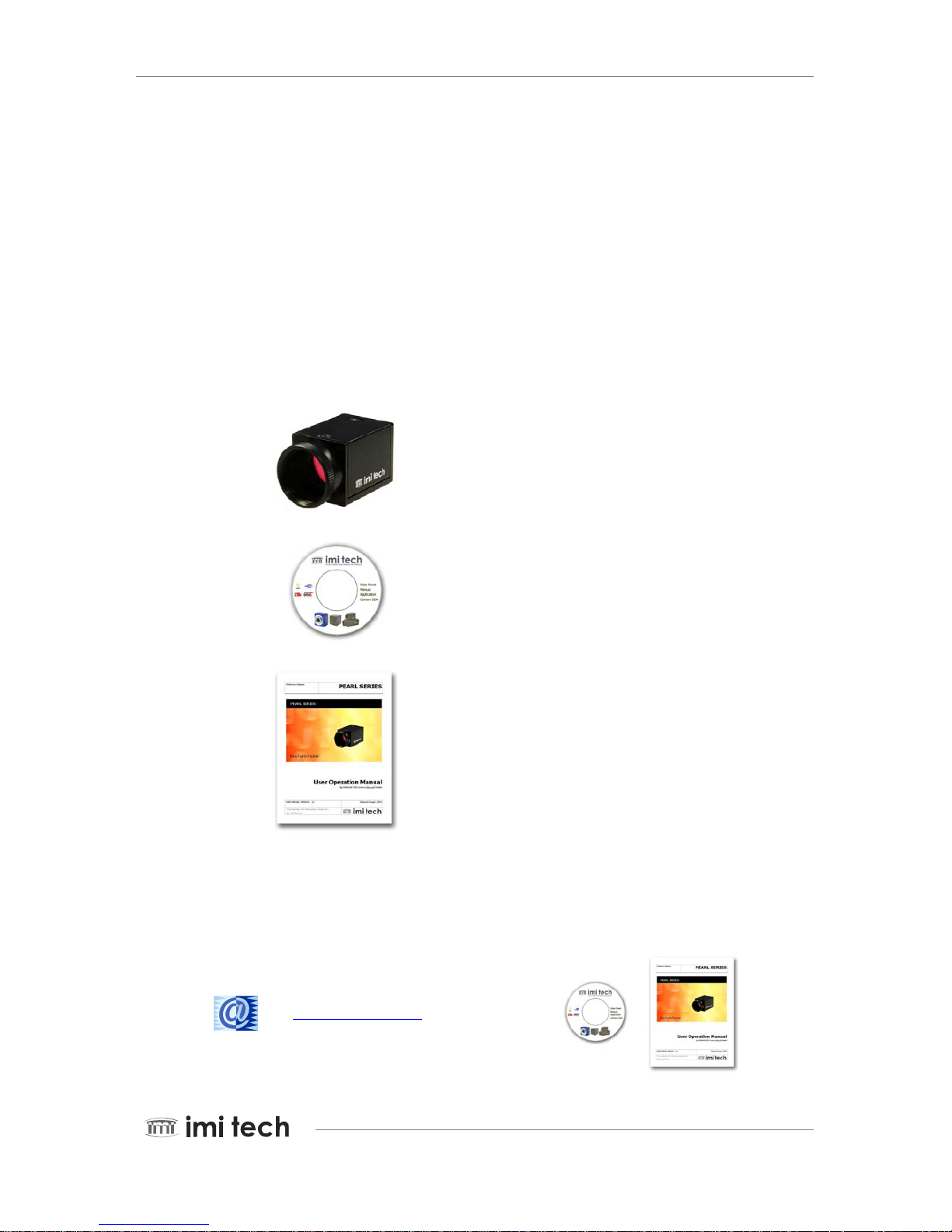
1.2. Components
Components in our package
Following components are included in the camera package. Some accessories are provided by software or website
to download.
PEARL SERIES
CAMERA UNIT
Detachable Filter
(Dummy Filter for B/W Series
Optical Low Pass filter for Color Models).
FIREWIRE
TM
Digital Imaging CD
Driver
Demo Software
ImCam API Library
Manuals
User Manual
Downloadable Software
Latest Update of Firmware and Demo Applications are available on our website.
http://www.imi-tech.com
Pioneer in Digital Vision Technology

PEARL SERIES Operation Manual Page 3
Pioneer in Digital Vision Technology
1.3. Optional Accessories
Machine Vision CCD Lens
FIREWIRETM OHCI Adapter
FIREWIRE
TM
PC-Card Bus Adapter
FIREWIRETM Cable
FIREWIRE
TM
Genders
FIREWIRETM Hub Repeater
Tri p od Pl ate

Page 4 PEARL SERIES Operation Manual
1.4. Dimension and Description
Camera Body Size : 29 (w) x 29 (H) x 39(D) mm
Camera Body Weight : approx. 63 gram
< IMx-xxFT Cameras >
< IMx-xxFC Cameras >
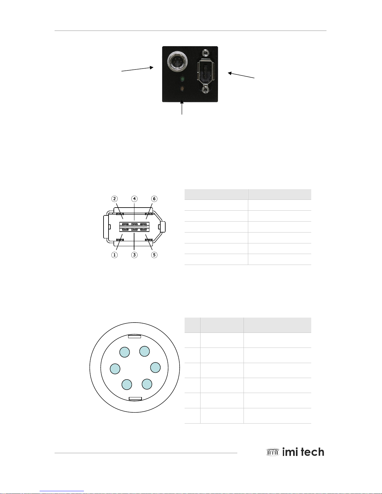
1.5. Camera Interface
The PEARL Series camera interface is located on the back of the camera (assuming lens mount is front) as per the
following.
Pioneer in Digital Vision Technology
PEARL SERIES Operation Manual Page 5
Pioneer in Digital Vision Technology
Trigger
Connector
FIREWIRETM Port
Status LED
1.6. FIREWIRE Port
The industry standard FireWireTM (IEEE-1394) port has the following pin assignment. Data and control of the
camera are provided via FireWire
TM
and camera power can also be supplied by FireWireTM
Pin Signal
1 VP
2 VG(Ground)
3 TPB-
4 TPB+
5 TPA
6 TPA-
CAUTION: DO NOT reverse the polarity. This could result in damage to the camera.
1.6.1. Trigger Connector Port
External Trigger Connector provides the access to multiple I/O.
<Camera Side>
Pin I/O Signal Name
1 O TX232
2 I RX232
3 X NC
4 O Strobe
5 I Ext. Trigger
6 I GND
⑥
①
⑤
②
④
③
Remark : NC pins must have no connection
Page 6 PEARL SERIES Operation Manual
1.6.2. Status LED
LED Status Isochronous Channel Packet Transfer
RED Disable NO
GREEN Enable YES
OFF Enable NO
Remark : Also when power off, LED is OFF
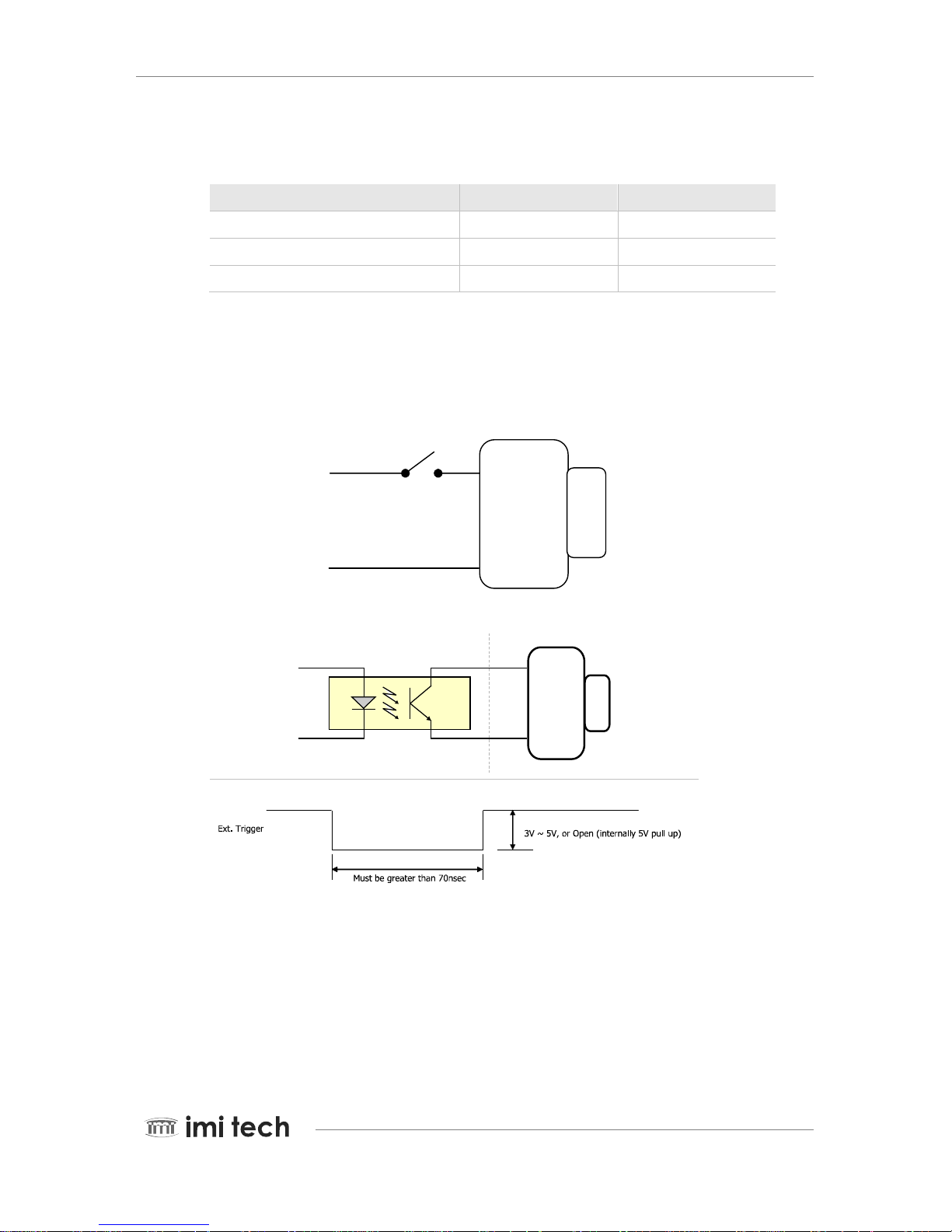
1.7. Electrical Operating Condition
Trigger
Method1
Method2 [IMI Recommend]
User Side
T
rigger
Opto. Coupler
Camera Side
FT Series
Camera
External
Trigger
Pin
GND Pin
R
ecommended Trigger Example
Electrical Specification
Pioneer in Digital Vision Technology
Ext. Trigger signal
Cameras
Ext. Trigger GND
FC Cameras Same
PEARL SERIES Operation Manual Page 7
Pioneer in Digital Vision Technology
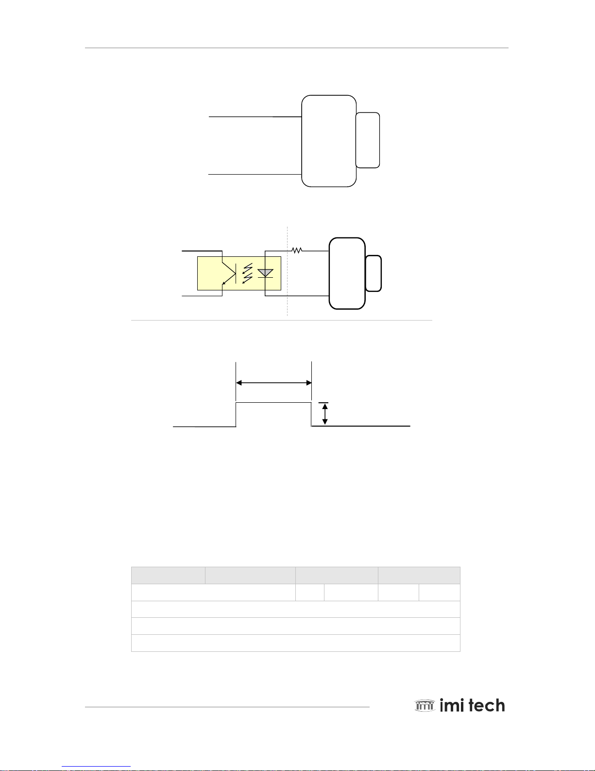
Strobe
Method1
Method2 [IMI Recommend]
User Side
Strobe
Opto. Coupler
Camera Side
FT Series
Camera
Strobe Pin
Active High
GND Pin
GND
220 Ω
R
ecommended Strobe Example
Electrical Specification
1.8. Pixel Data
The PEARL Series complies with the IIDC 1394-Based Digital Camera Specification V1.31 where data packets are
transmitted by a FireWire
TM
interface as isochronous packets. Every video format, mode and frame rate has a
different video data format. (Pixel data source: IIDC V1.31 Specification)
Isochronous Data Block Packet Format
0 - 7 8 - 15 16 - 23 24 - 31
Data Length tg Channel tCode Sy
Header CRC
Video data payload
Data CRC
FT Cameras
Strobe signal
Strobe GND
FC Cameras Same
App 2msec
User can set strobe
Strobe
4V ~ 5V

Page 8 PEARL SERIES Operation Manual
Pioneer in Digital Vision Technology
Where the following fields are defined in the IEEE 1394 standard as:
data_length : number of bytes in the data field tg : (tag field) shall be set to zero
channel : isochronous channel number, as programmed in the iso_channel field of the cam_sta_ctrl register
tCode : (transaction code) shall be set to the isochronous data block packet tCode
sy : (synchronization value) shall be set to 0001h on the first isochronous data block of a frame, and shall be set to
zero on all other isochronous data blocks
Video data payload : shall contain the digital video information, as defined in the following sections
of the
Video data Payload Structure
Pn : Pixel number / packet .
K : Pn x n (n = 0…..N-1)
(Pn x N = Total pixel number /frame)
<YUV (4: 2: 2) format >
U-(K+0) Y-(K+0) V-(K+0) Y-(K+1)
U-(K+2) Y-(K+2) V-(K+2) Y-(K+3)
U-(K+4) Y-(K+4) V-(K+4) Y-(K+5)
U-(K+Pn-6) Y-(K+Pn-6) V-(K+Pn-6) Y-(K+Pn-5)
U-(K+Pn-4) Y-(K+Pn-4) V-(K+Pn-4) Y-(K+Pn-3)
U-(K+Pn-2) Y-(K+Pn-2) V-(K+Pn-2) Y-(K+Pn-1)
<YUV (4: 1: 1) format >
U-(K+0) Y-(K+0) Y-(K+1) V-(K+0)
Y-(K+2) Y-(K+3) U-(K+4) Y-(K+4)
Y-(K+5) V-(K+4) V-(K+4) Y-(K+5)
U-(K+Pn-8) Y-(K+Pn-8) Y-(K+Pn-7) V-(K+Pn-8)
Y-(K+Pn-6) Y-(K+Pn-5) U-(K+Pn-4) Y-(K+Pn-4)
Y-(K+Pn-3) V-(K+Pn-4) Y-(K+Pn-2) Y-(K+Pn-1)
<Y(Mono) Format >
Y-(K+ 0) Y-(K+1 ) Y-(K+2) Y-( K+3)
Y-(K+ 4) Y-(K+5 ) Y-(K+6) Y-( K+7)
Y-(K+ Pn-8) Y-( K+ Pn-7) Y-( K+Pn-6) Y-( K+Pn-5)
PEARL SERIES Operation Manual Page 9
Pioneer in Digital Vision Technology
Y-(K+Pn-4) V-(K+Pn-3) Y-(K+Pn-2) Y-(K+Pn-1)
<Y(Mono) Format >
High Byte Low Byte
Y-(K+ 0) Y-(K+1 )
Y-(K+ 2) Y-(K+3 )
Y-(K+ Pn-4) Y-( K+ Pn-3)
V-(K+Pn-2) Y-(K+Pn-1)
Data Structure
<Y, R, G, B >
Each component has 8 bit data. The data type is “Unsigned Char”
Signal Level (Decimal) Data (Hexadecimal)
Highest 255 0xFF
254 0xFE
.
.
.
.
1 0x01
Lowest 0 0x00
<U, V>
Each component has 8 bit data. The data type is “Straight Binary”
Signal Level (Decimal) Data (Hexadecimal)
Highest(+) 127 0xFF
126 0xFE
.
.
.
.
1 0x81
Lowest 0 0x80
-1 0x7F
.
.
.
.
-127 0x01
Lowest -128 0x00

Page 10 PEARL SERIES Operation Manual
Pioneer in Digital Vision Technology
<Y(Mono16)>
Y component has 16 bit data. The data type is “Unsigned Short(big-endian)”
Y Signal Level (Decimal) Data (Hexadecimal)
Highest 65535 0xFFFF
65534 0xFFFE
.
.
.
.
1 0x0001
Lowest 0 0x0000
1.9. Environmental Requirements
Operation Temperature : -5°C ~ 45°C / Storage Temperature : -20°C ~ 65°C
Avoid operation in environment of high humidity over 90% and allow sufficient airflow for prevention of heat
buildup
PEARL SERIES Operation Manual Page 11
Pioneer in Digital Vision Technology
2. Basic Installation
The Pearl Series operates in connection with a PC running an operation system such as MS Windows or Linux.
Basic installation consists of driver installation, connecting the camera and loading the demo application software.
Please refer to the demo application software manual for details.
2.1. Recommended System Requirement
Requirements Details and Description
Operating System Windows 2000(SP4), Windows XP(SP2) or higher
CPU Intel Pentium 4 1.5 GHz or equivalent AMD CPU or higher
System Memory 256 M Byte or more
Video Adapter 1280 x 1024 with 24 bit color or higher
Hard Disk Drive 40 GB or higher
Optical Drive CDROM or DVDROM
FIREWIRETM FIREWIRETM OHCI PCI or PC-Card Adaptor
Cable Standard FIREWIRETM 6P-6P cable or 4P to 6P cable ( for Notebooks )
Software
DirectX 9.0 or higher ( 9.0b or higher for Windows XP ) IMI Tech Digital Imaging CD
(ImCam Application and Driver ) or other Windows Application such as amcap.exe
Remark : Other software or hardware may be required for user specific applications.
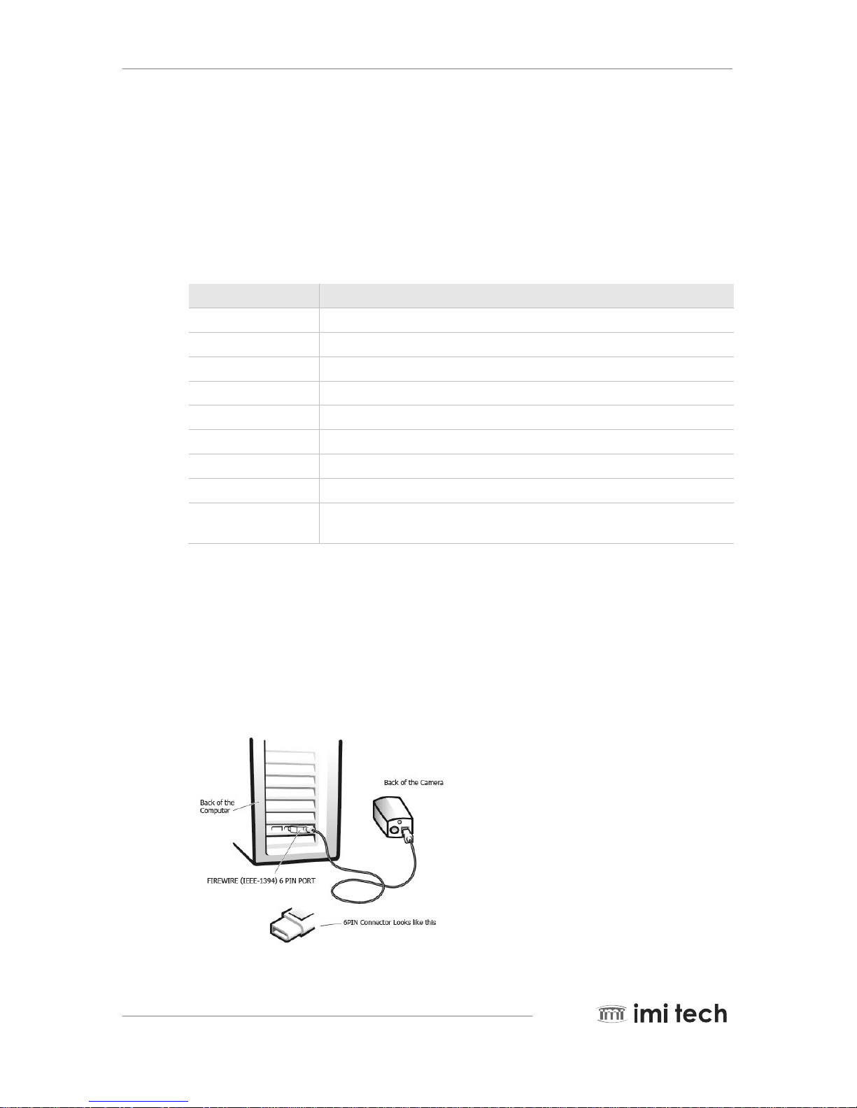
2.2. Hardware Installation
Basic camera installation is a very simple 3-STEP Process as follows. ( Also check the figure below )
STEP 1. Turn to the back of the computer and locate the FIREWIRE port.
(Note : some might have FIREWIRE port in the front)
STEP 2. Plug one end of the FIREWIRETE cable to the computer’s FIREWIRE port.
STEP 3. Plug the other end of the FIREWIRET cable to the camera’s FIREWIRE port.
Basic
Hardware Installation
and
Camera Connection
Page 12 PEARL SERIES Operation Manual
2.3. Software Installation
Important !!, DO NOT CONNECT THE CAMERA BEFORE INSTALLING THE SOFTWARE!!
Insert the IMI Digital Imaging CD which will auto install the camera drivers and demo applications. (For details of
the application and the driver please refer to the demo application manual.)
FIREWIRETM Digital Imaging CD
Driver
Demo Software
ImCam API Library
Manuals
NOTE: Software Installation should precede Hardware Installation
Pioneer in Digital Vision Technology
PEARL SERIES Operation Manual Page 13
Pioneer in Digital Vision Technology
3.1.1.
3. PEARL Series Camera Specifications
3.1. Black and White Camera
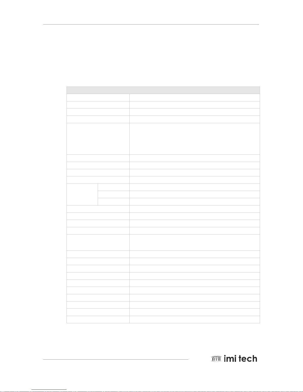
IMB-20FT Specification
Features( IMB-20FT)
Image Sensor Type 1/1.8-inch Interline CCD (Sony ICX274AL)
Effective pixels 2,010,000 pixels 1628(H) x 1236(V)
Picture Size 1600x1200, 1280x960, 1024x768, 800x600, 640x480
Cell Size(um) 4.4x4.4
Real Frame Rate
15, 7.5, 3.75, 1.875 / Y8, Y16
16 (1600x1200, Format 7 mode 0)
32 (640x480, Format 7 mode 0)
29 (800x600, Format7 mode 1, 2x2 binning)
29 (1600x600, Format7 mode 2, 1x2 binning)
Lens Mount C Mount
Scanning System Progressive System
Binning 2x2, 1x2
Format7 Partial Scan (Unit: 4x4)
Trigger
Edge Rising Edge or Falling Edge
Mode 0, 1, 2, 3, 4, 5, 14,15
Source External Trigger or Software Trigger
Strobe Active High, Support Normal Mode or Trigger Mode.
Multi-camera auto sync -144 us ~ +144 us at 15,7.5 frame rate
Memory Save/Load 16 Channels(0:factory, 1~4:feature, 5~15:mode/feature)
One-shot/Multi-shot 65535 Shots
Control Functions
Brightness, Sharpness, Gamma, Auto-Exposure, Shutter, Gain, Pan/Tilt,
High speed up trigger frame rate
SIO(RS-232) IIDC v1.31 version : Path through or IMI-Tech Command
Frame Delay from Read-out Min. 106us
Digital Interface / Transfer Rate IEEE 1394 1 port(6pin) / 400Mpbs
Gain 0 ~ 18 dB (Manual or Auto)
Shutter Speed 1 usec ~ 3600 sec (Manual or Auto)
Data Depth 12 bit
S/N Ratio 56dB or better
Supply Voltage & Power Less than 2 Watts (@12V DC)
External Dimension / Weight 29(W) x 29(H) x 39(D) mm / Approx 63g
Operation Temp. -5°C to 45°C
Remark : Camera Specification and features are subject to change without notice.
Page 14 PEARL SERIES Operation Manual
Pioneer in Digital Vision Technology
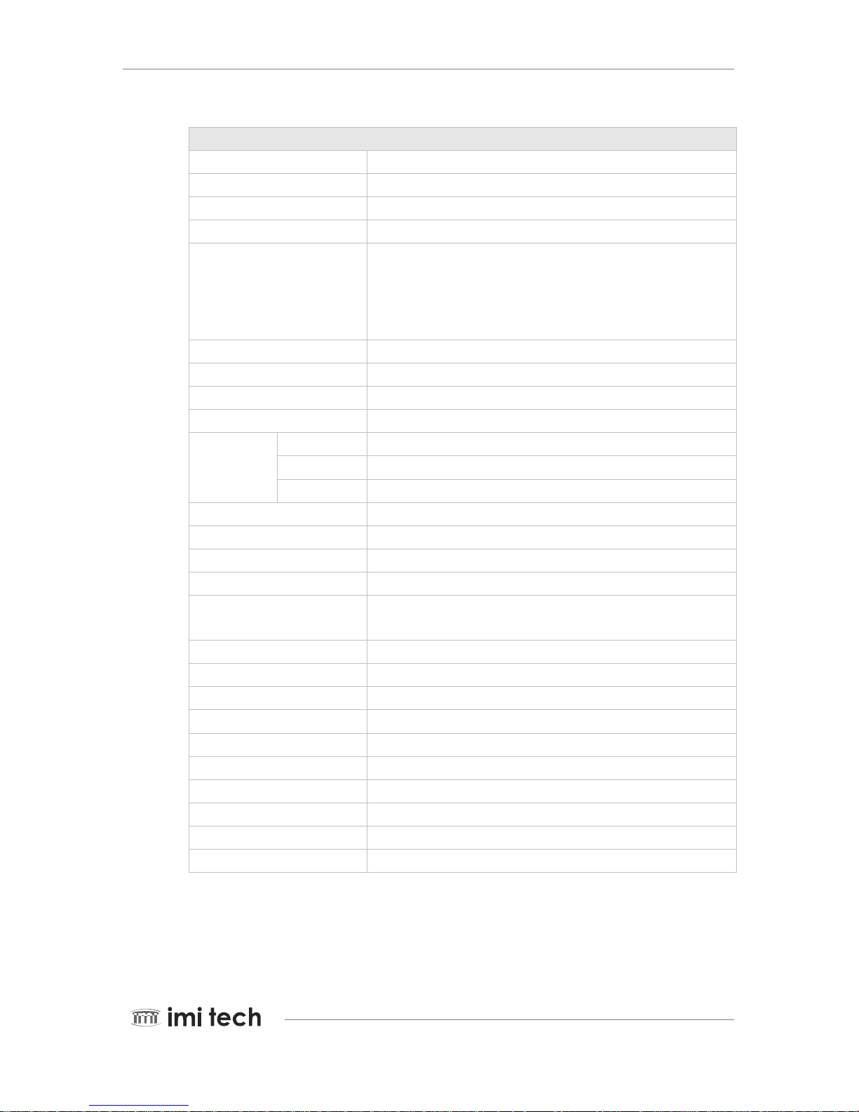
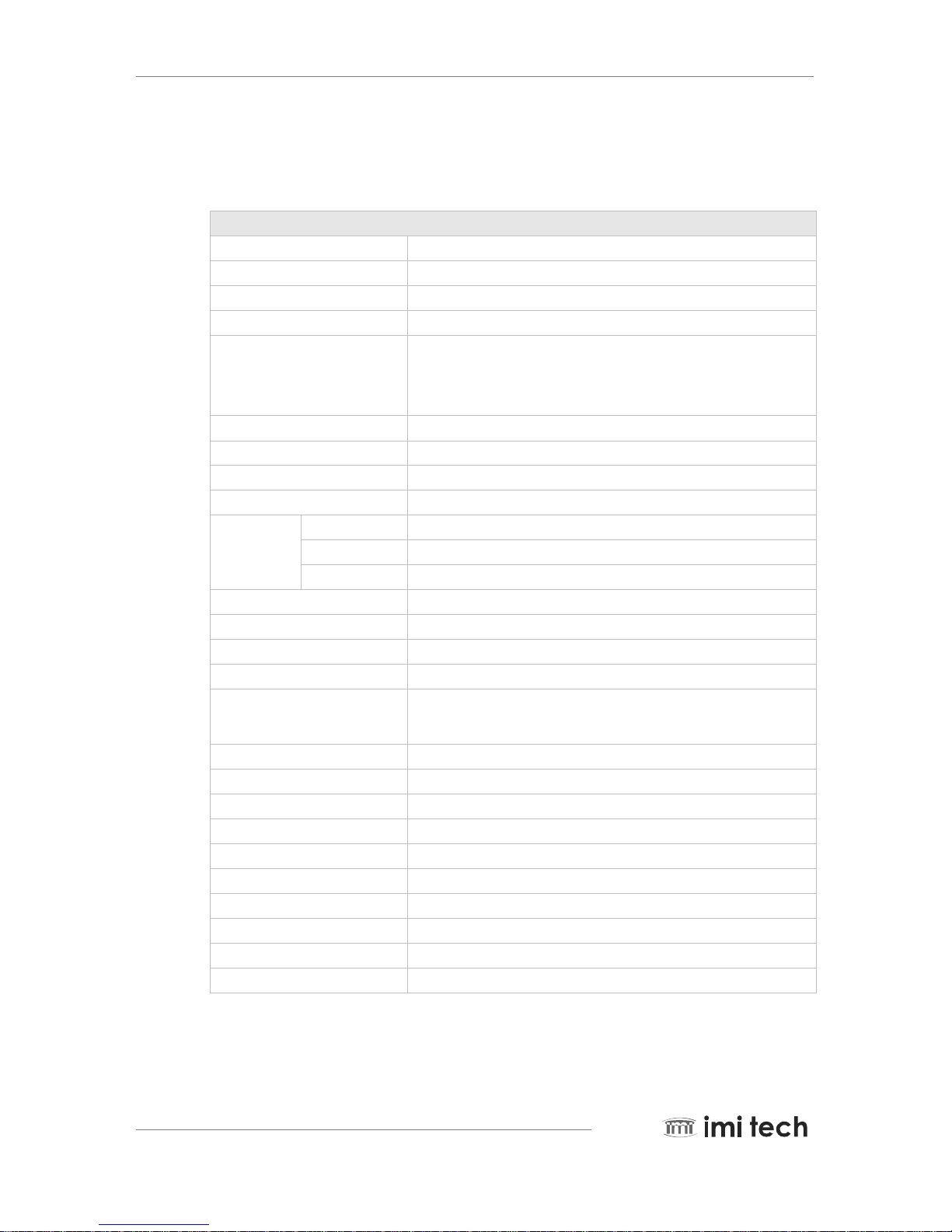
3.1.2. IMB-17FT Specification
Features( IMB-17FT)
Image Sensor Type 1/2-inch Interline CCD (Sony ICX267AL)
Effective pixels 1,450,000 pixels 1388(H) x 1040(V)
Picture Size 1388x1040, 1280x960, 1024x768, 800x600, 640x480
Cell Size(um) 4.65x4.65
Real Frame Rate
15, 7.5, 3.75, 1.875 / Y8, Y16
20 (1388x1040, Format 7 mode 0)
35 (1388x520, Format 7 mode 0)
37(688x516, Format 7 mode 1 2x2 binning)
Lens Mount C Mount
Scanning System Progressive System
Binning 2x2, 1x2
Format7 Partial Scan (Unit: 4x4)
Trigger
Edge Rising Edge or Falling Edge
Mode 0, 1, 2, 3, 4, 5, 14,15
Source External Trigger or Software Trigger
Strobe Active High, Support Normal Mode or Trigger Mode.
Multi-camera auto sync -144 us ~ +144 us at 15,7.5 frame rate
Memory Save/Load 16 Channels(0:factory, 1~4:feature, 5~15:mode/feature)
One-shot/Multi-shot 65535 Shots
Control Functions
Brightness, Sharpness, Gamma, Auto-Exposure, Shutter, Gain, Pan/Tilt,
High speed up trigger frame rate
SIO(RS-232) IIDC v1.31 version : Path through or IMI-Tech Command
Frame Delay from Read-out Min. 106us
Digital Interface / Transfer Rate IEEE 1394 1 port(6pin) / 400Mpbs
Gain 0 ~ 18 dB (Manual or Auto)
Shutter Speed 1 usec ~ 3600 sec (Manual or Auto)
Data Depth 12 bit
S/N Ratio 56dB or better
Supply Voltage & Power Less than 2 Watts (@ 12 V DC)
External Dimension / Weight 29(W) x 29(H) x 39(D) mm / Approx 63g
Operation Temp. -5°C to 45°C
Remark : Camera Specification and features are subject to change without notice.
PEARL SERIES Operation Manual Page 15
Pioneer in Digital Vision Technology
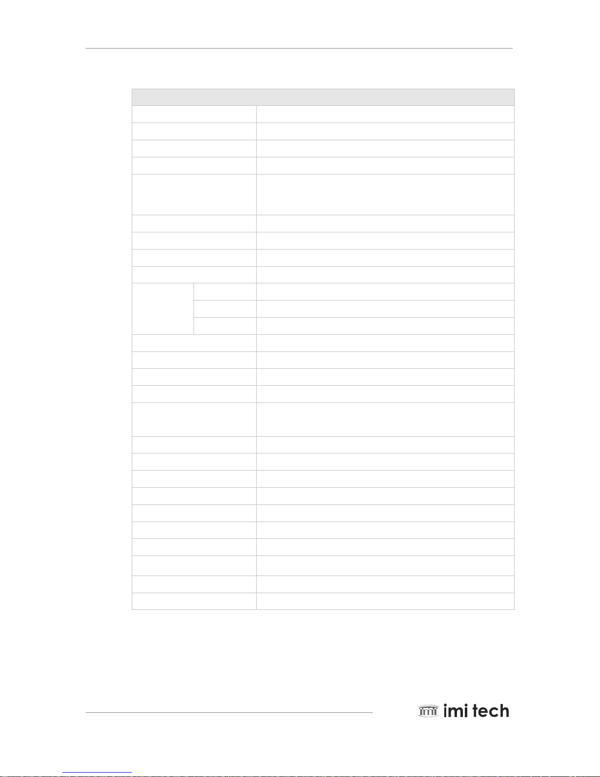
3.1.3. IMB-16FT Specification
Features( IMB-16FT)
Image Sensor Type 1/3-inch Interline CCD (Sony ICX445AL)
Effective pixels 1,251,936 pixels 1296(H) x 966(V)
Picture Size 1288 x 964
Cell Size(um) 3.75 x 3.75
Real Frame Rate
Lens Mount C Mount
Scanning System Progressive System
Binning Not supported
Format7 Partial Scan (Unit: 4x4)
Trigger
Edge Rising Edge or Falling Edge
Mode 0, 1, 2, 3, 4, 5, 14, 15
Source External Trigger or Software Trigger
Strobe Active High, Support Normal Mode or Trigger Mode.
Multi-camera auto sync -144 us ~ +144 us at 30,15,7.5 frame rate
Memory Save/Load 16 Channels(0:factory, 1~4:feature, 5~15:mode/feature)
One-shot/Multi-shot 65535 Shots
Control Functions
Brightness, Sharpness, Gamma, Auto-Exposure, Shutter, Gain, Pan/Tilt,
High speed up trigger frame rate
SIO(RS-232) IIDC v1.31 version : Path through or IMI-Tech Command
Frame Delay from Read-out Min. 43us
Digital Interface / Transfer Rate IEEE 1394 1 port(6pin) / 400Mpbs
Gain 0 ~ 18 dB (Manual or Auto)
Shutter Speed 1 usec ~ 3600 sec (Manual or Auto)
Data Depth 12 bit
S/N Ratio 56dB or better
Supply Voltage & Power Less than 2 Watts (@ 12 V DC)
External Dimension / Weight 29(W) x 29(H) x 39(D) mm / Approx 63g
Operation Temp. -5°C to 45°C
Remark : Camera Specification and features are subject to change without notice.

Page 16 PEARL SERIES Operation Manual
Pioneer in Digital Vision Technology
3.1.4. IMB-15FT Specification
Features( IMB-15FT)
Image Sensor Type 1/3-inch Interline CCD (Sony ICX204AL)
Effective pixels 800,000 pixels 1034(H) x 779(V)
Picture Size 1024x768, 800x600, 640x480, 320x240
Cell Size(um) 4.65x4.65
Real Frame Rate
30, 15, 7.5, 3.75, 1.875 / Y8, Y16
30 (1024x768, Format 7 mode 0)
58 (1024x384, Format7 mode2, 1x2 binning)
58 (512x384, Format7 mode1, 2x2 binning)
Lens Mount C Mount
Scanning System Progressive System
Binning Not supported
Format7 Partial Scan (Unit: 4x4)
Trigger
Edge Rising Edge or Falling Edge
Mode 0, 1, 2, 3, 4, 5, 14, 15
Source External Trigger or Software Trigger
Strobe Active High, Support Normal Mode or Trigger Mode.
Multi-camera auto sync -144 us ~ +144 us at 30,15,7.5 frame rate
Memory Save/Load 16 Channels(0:factory, 1~4:feature, 5~15:mode/feature)
One-shot/Multi-shot 65535 Shots
Control Functions
Brightness, Sharpness, Gamma, Auto-Exposure, Shutter, Gain, Pan/Tilt,
High speed up trigger frame rate
SIO(RS-232) IIDC v1.31 version : Path through or IMI-Tech Command
Frame Delay from Read-out Min. 70us
Digital Interface / Transfer Rate IEEE 1394 1 port(6pin) / 400Mpbs
Gain 0 ~ 18 dB (Manual or Auto)
Shutter Speed 1 usec ~ 3600 sec (Manual or Auto)
Data Depth 12 bit
S/N Ratio 56dB or better
Supply Voltage & Power Less than 2 Watts (@ 12 V DC)
External Dimension / Weight 29(W) x 29(H) x 39(D) mm / Approx 63g
Operation Temp. -5°C to 45°C
Remark : Camera Specification and features are subject to change without notice.
PEARL SERIES Operation Manual Page 17
Pioneer in Digital Vision Technology
3.1.5. IMB-12FT Specification
Features (IMB-12FT)
Image Sensor 1/2-inch Interline CCD (ICX414AL)
Effective Pixels 330,000 pixels 659(H) x 494(V)
Picture Size 640 x 480, 320 x 240
Cell Size 9.9x9.9
Real Frame Rate
60, 30, 15, 7.5, 3.75, 1.875 / Y8, Y16
60 (640x480, Format 7 mode 0)
120 (640x240, Format7 mode2, 1x2 binning)
120 (320x240, Format7 mode1, 2x2 binning)
Lens Mount C-mount
Scanning System Progressive System
Binning 1x2, 2x2
Format 7 Partial Scan (Unit: 4x4)
Trigger
Edge Rising Edge or Falling Edge
Mode 0, 1, 2, 3, 4, 5, 14, 15
Source External Trigger or Software Trigger
Strobe Active High, Support Normal Mode or Trigger Mode.
Multi-camera auto sync -144 us ~ +144 us at 60,30,15,7.5 frame rate
Memory Save/Load 16 Channels(0:factory, 1~4:feature, 5~15:mode/feature)
One-shot/Multi-shot 65535 Shots
Control Functions
Brightness, Sharpness, Gamma, Auto-Exposure, Shutter, Gain, Pan/Tilt,
High speed up trigger frame rate
SIO(RS-232) IIDC v1.31 version : Path through or IMI-Tech Command
Frame Delay from Read-out Min. 43us
Digital Interface / Transfer Rate IEEE 1394 1 port(6pin) / 400Mbps
Gain 0 ~ 18 dB (Manual or Auto)
Shutter Speed 1 usec ~ 3600 sec (Manual or Auto)
Data Depth 12 bit
S/N Ratio 56dB or better
Supply Voltage & Power Less than 2 Watts (@ 12 V DC)
External Dimension / Weight 29(W) x 29(H) x 39(D) mm / Approx 63g
Operation Temp. -5°C to 45°C
Remark : Camera Specification and features are subject to change without notice.
Page 18 PEARL SERIES Operation Manual
Pioneer in Digital Vision Technology
3.1.6. IMB-11FT Specification
Features (IMB-11FT)
Image Sensor 1/3-inch Interline CCD (Sony ICX424AL)
Effective Pixels 330,000 pixels 659(H) x 494(V)
Picture Size 640 x 480, 320 x 240
Cell Size 7.40x7.40
Real Frame Rate
60, 30, 15, 7.5, 3.75, 1.875 / Y8, Y16
60 (640x480, Format 7 mode 0)
120 (640x240, Format7 mode2, 1x2 binning)
120 (320x240, Format7 mode1, 2x2 binning)
Lens Mount C-mount
Scanning System Progressive System
Binning Not supported
Format 7 Partial Scan (Unit: 4x4)
Trigger
Edge Rising Edge or Falling Edge
Mode 0, 1, 2, 3, 4, 5, 14, 15
Source External Trigger or Software Trigger
Strobe Active High, Support Normal Mode or Trigger Mode.
Multi-camera auto sync -144 us ~ +144 us at 60,30,15,7.5 frame rate
Memory Save/Load 16 Channels(0:factory, 1~4:feature, 5~15:mode/feature)
One-shot/Multi-shot 65535 Shots
Control Functions
Brightness, Sharpness, Gamma, Auto-Exposure, Shutter, Gain, Pan/Tilt,
High speed up trigger frame rate
SIO(RS-232) IIDC v1.31 version : Path through or IMI-Tech Command
Frame Delay from Read-out Min. 43us
Digital Interface / Transfer Rate IEEE 1394 1 port(6pin) / 400Mbps
Gain 0 ~ 18 dB (Manual or Auto)
Shutter Speed 1 usec ~ 3600 sec (Manual or Auto)
Data Depth 12 bit
S/N Ratio 56dB or better
Supply Voltage & Power Less than 2 Watts (@ 12 V DC)
External Dimension / Weight 29(W) x 29(H) x 39(D) mm / Approx 63g
Operation Temp. -5°C to 45°C
Remark : Camera Specification and features are subject to change without notice.
PEARL SERIES Operation Manual Page 19
Pioneer in Digital Vision Technology
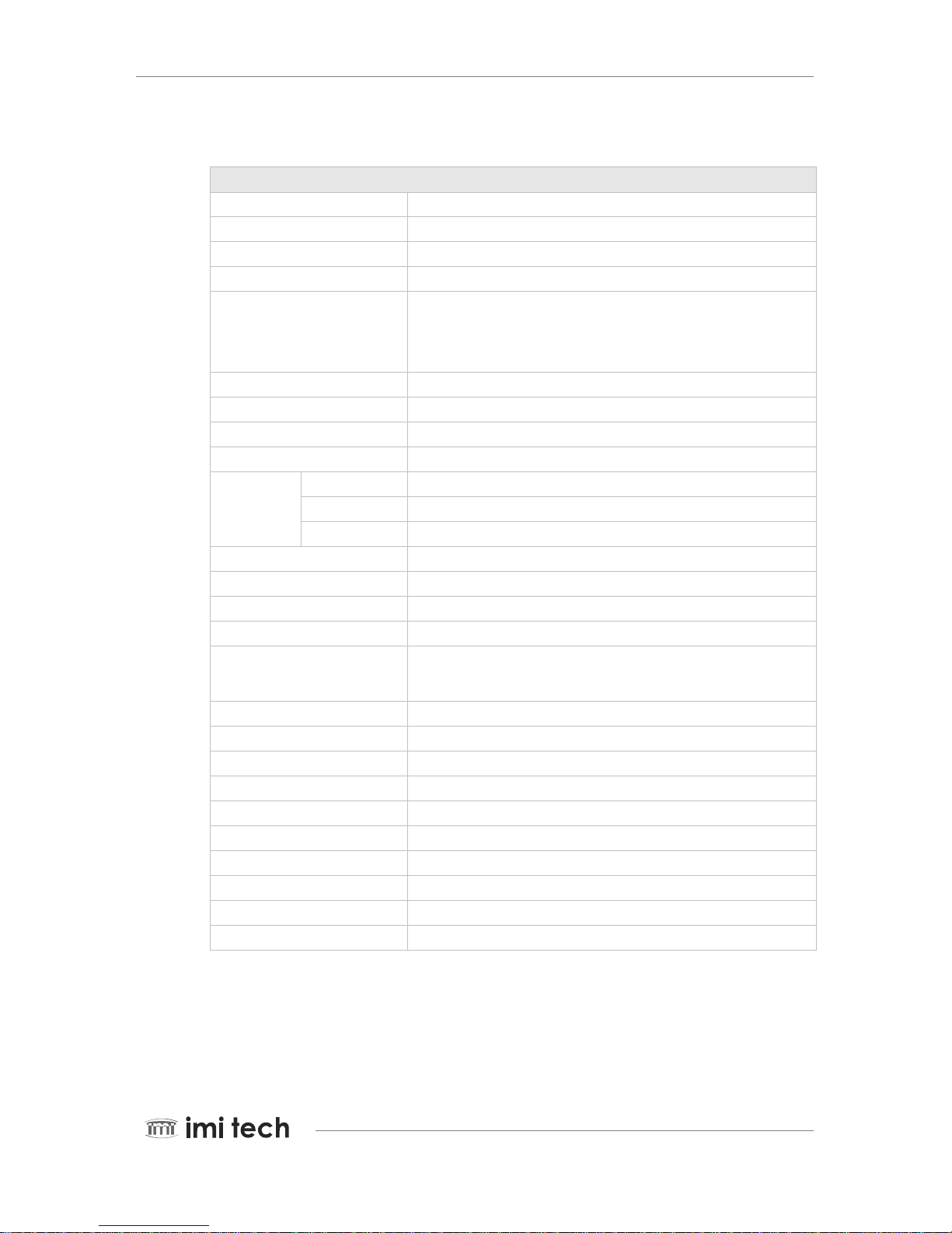
3.1.7. IMB-16FC Specification
Features (IMB-16FC)
Image Sensor 1/2" MT9M001 (Micron CMOS)
Effective Pixels 1,310,720 pixels 1280(H) x 1024(V)
Picture Size 1280x1024, 1280x960, 1024x768, 800x600, 640x480
Cell Size(um) 5.2 x 5.2
Real Frame Rate
60, 30, 15, 7.5, 3.75 / Y8, Y16
24 (1280x1024, Format 7 mode 0)
Lens Mount C Mount
Scanning System Progressive System
Binning Not supported
Format 7 Partial Scan (Unit: 4x4)
Trigger
Edge Rising Edge or Falling Edge
Mode 0
Source External Trigger or Software Trigger
Strobe Active High, Support Normal Mode or Trigger Mode.
Multi-camera auto sync Not supported
Memory Save/Load 16 Channels(0:factory, 1~4:feature, 5~15:mode/feature)
One-shot/Multi-shot Not supported
Control Functions Brightness, Sharpness, Gamma, Auto-Exposure, Shutter, Gain, Pan/Tilt
SIO(RS-232) IIDC v1.31 version : Path through or IMI-Tech Command
Frame Delay from Read-out Min. 70us
Digital Interface / Transfer Rate IEEE 1394 1 port(6pin) / 400Mpbs
Gain 0 ~ 18 dB (Manual or Auto)
Shutter Speed 60 usec ~ 500 msec (Manual or Auto)
Data Depth 10 bit
S/N Ratio 45dB or better
Supply Voltage & Power
Less than 2Watts(@12V DC)
External Dimension / Weight 29(W) x 29(H) x 39(D) mm / Approx 63g
Operation Temp. -5°C to 45°C
Remark : Camera Specification and features are subject to change without notice.

Page 20 PEARL SERIES Operation Manual
Pioneer in Digital Vision Technology
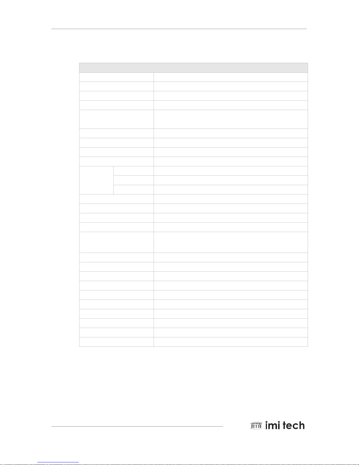
3.1.8. IMB-13FC Specification
Features( IMB-13FC)
Image Sensor Type 1/3" MT9V022177ATM (Micron CMOS)
Effective pixels 360,960 pixels 752(H) x 480(V)
Picture Size 752x480, 640x480, 376x240
Cell Size(um) 6.0 x 6.0
Real Frame Rate
60, 30, 15, 7.5, 3.75
60(752x480, Format 7 mode 0), 110(376x240, Format 7 mode 1, 2x2binning)
Lens Mount C Mount
Scanning System Progressive System
Binning 2 x 2
Format7 Partial Scan (Unit: 4x4)
Trigger
Edge Rising Edge or Falling Edge
Mode 0
Source External Trigger or Software Trigger
Strobe Active High, Support Normal Mode or Trigger Mode.
Multi-camera auto sync Not supported
Memory Save/Load 16 Channels(0:factory, 1~4:feature, 5~15:mode/feature)
One-shot/Multi-shot Not supported
Control Functions Brightness, Sharpness, Gamma, Auto-Exposure, Shutter, Gain, Pan/Tilt
SIO(RS-232) IIDC v1.31 version : Path through or IMI-Tech Command
Frame Delay from Read-out Min. 70us
Digital Interface / Transfer Rate IEEE 1394 1 port(6pin) / 400Mpbs
Gain 0 ~ 18 dB (Manual or Auto)
Shutter Speed 93 usec ~ 100 msec (Manual or Auto)
Data Depth 10 bit
S/N Ratio 45dB or better
Supply Voltage & Power Less than 2Watts(@12V DC)
External Dimension / Weight 29(W) x 29(H) x 39(D) mm / Approx 63g
Operation Temp. -5°C to 45°C
Remark : Camera Specification and features are subject to change without notice.
PEARL SERIES Operation Manual Page 21
Pioneer in Digital Vision Technology
3.2.1.
3.2. Color Cameras
IMC-20FT Specification
Features( IMC-20FT)
Image Sensor Type 1/1.8-inch Interline CCD (Sony ICX274AQ)
Effective pixels 2,010,000 pixels 1600(H) x 1200(V)
Picture Size 1600x1200, 1280x960, 1024x768, 800x600, 640x480
Cell Size(um) 4.4x4.4
Real Frame Rate
15, 7.5, 3.75, 1.875 / Y8, Y16, YUV422
16 (1600x1200, Format 7 mode 0)
32 (640x480, Format 7 mode 0)
29 (800x600, Format7 mode 1, 2x2 binning)
29 (1600x600, Format7 mode 2, 1x2 binning)
Lens Mount C Mount
Scanning System Progressive System
Binning 2x2, 1x2
Format7 Partial Scan (Unit: 4x4)
Trigger
Edge Rising Edge or Falling Edge
Mode 0, 1, 2, 3, 4, 5, 14,15
Source External Trigger or Software Trigger
Strobe Active High, Support Normal Mode or Trigger Mode.
Multi-camera auto sync -144 us ~ +144 us at 15,7.5 frame rate
Memory Save/Load 16 Channels(0:factory, 1~4:feature, 5~15:mode/feature)
One-shot/Multi-shot 65535 Shots
Control Functions
Brightness, Sharpness, Gamma, Auto-Exposure, Shutter, Gain, Pan/Tilt,
High speed up trigger frame rate, AWB
SIO(RS-232) IIDC v1.31 version : Path through or IMI-Tech Command
Frame Delay from Read-out Min. 106us
Digital Interface / Transfer Rate IEEE 1394 1 port(6pin) / 400Mpbs
Gain 0 ~ 18 dB (Manual or Auto)
Shutter Speed 1 usec ~ 3600 sec (Manual or Auto)
Data Depth 12 bit
S/N Ratio 56dB or better
Supply Voltage & Power Less than 2Watts(@12V DC)
External Dimension / Weight 29(W) x 29(H) x 39(D) mm / Approx 63g
Operation Temp. -5°C to 45°C
Remark : Camera Specification and features are subject to change without notice.

Page 22 PEARL SERIES Operation Manual
Pioneer in Digital Vision Technology
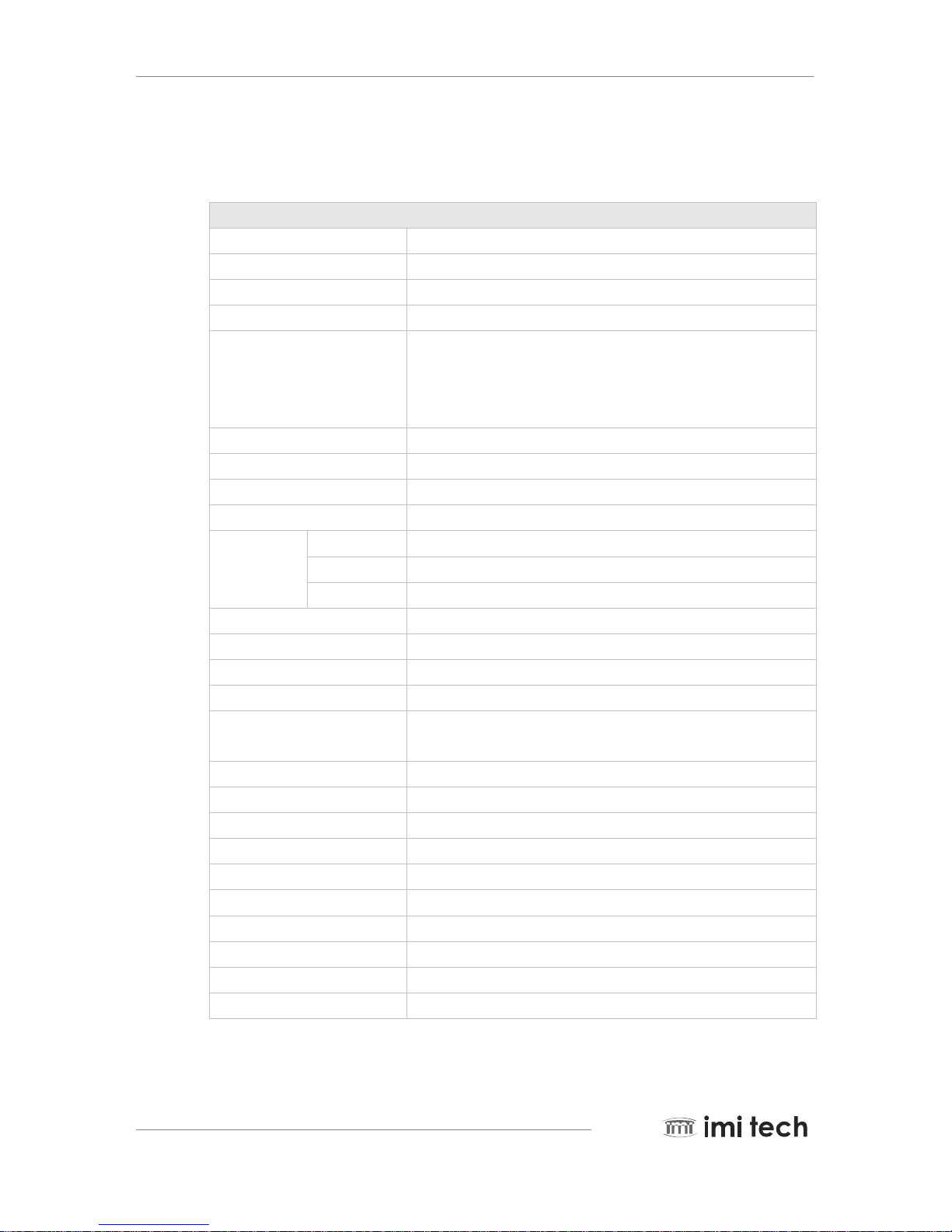
3.2.2. IMC-17FT Specification
Features( IMC-17FT)
Image Sensor Type 1/2-inch Interline CCD (Sony ICX267AK)
Effective pixels 1,450,000 pixels 1388(H) x 1036(V)
Picture Size 1388x1036, 1280x960, 1024x768, 800x600, 640x480
Cell Size(um) 4.65x4.65
Real Frame Rate
15, 7.5, 3.75, 1.875 / Y8, Y16, YUV422
20 (1388x1036, Format 7 mode 0)
35 (1388x520, Format 7 mode 0)
Lens Mount C Mount
Scanning System Progressive System
Binning Not supported
Format7 Partial Scan (Unit: 4x4)
Trigger
Edge Rising Edge or Falling Edge
Mode 0, 1, 2, 3, 4, 5, 14,15
Source External Trigger or Software Trigger
Strobe Active High, Support Normal Mode or Trigger Mode.
Multi-camera auto sync -144 us ~ +144 us at 15,7.5 frame rate
Memory Save/Load 16 Channels(0:factory, 1~4:feature, 5~15:mode/feature)
One-shot/Multi-shot 65535 Shots
Control Functions
Brightness, Sharpness, Gamma, Auto-Exposure, Shutter, Gain, Pan/Tilt,
High speed up trigger frame rate, AWB
SIO(RS-232) IIDC v1.31 version : Path through or IMI-Tech Command
Frame Delay from Read-out Min. 106us
Digital Interface / Transfer Rate IEEE 1394 1 port(6pin) / 400Mpbs
Gain 0 ~ 18 dB (Manual or Auto)
Shutter Speed 1 usec ~ 3600 sec (Manual or Auto)
Data Depth 12 bit
S/N Ratio 56dB or better
Supply Voltage & Power Less than 2Watts(@12V DC)
External Dimension / Weight 29(W) x 29(H) x 39(D) mm / Approx 63g
Operation Temp. -5°C to 45°C
Remark : Camera Specification and features are subject to change without notice.
 Loading...