

Page 1
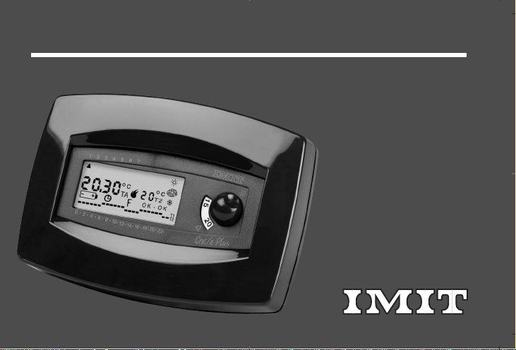
CRX/E PLUS
Instruction manual
Page 2
SUMMARY
1. Introduction pag. 3
2. Technical data 4
3. Display readings key 6
4. Chronothermostat controls key 7
5. Dimensions 8
6. Installation and connections 9
7. Chronothermostat start-up 16
8. Clock setting 16
2
9. Program setting 19
10. Temperature setting 21
11. Normal operation conditions 22
12. Override mode 22
13. Summer/winter setting 23
14. Differential setting 24
15. Knob lock 24
16. Unit reset 25
17. Troubleshooting 26
Page 3

1. INTRODUCTION
Thank you for your confidence in our company and for choosing our products.
This is an easy-to-use, high-styling design, 7-DAY electronic PROGRAMMABLE THERMOSTAT.It allows an extremely accurate room temperature adjustment in the hosting room;thus meeting any users' needs as far as room COMFORT
IN ACCORDANCE WITH THE STANDARDS:
• EN 60730-1 and later updating
• EN 60730-2-7
• EN 60730-2-9
IN ACCORDANCE WITH THE GUIDELINES:
• B.T.73/23/EEC
• E.M.C.89/336/EEC and later updating 93/68/EEC
3
Page 4

2. TECHNICAL DATA
POWER SUPPLY= N° 2 1.5V alkaline batteries, type LR6
NORMAL TEMPERA TURE RANGE “T1”= 5÷30°C
REDUCED TEMPERA TURE RANGE “T2”= 6°/14°/16°/18°C (winter mode)
38°/30°/28°/26°C (summer mode)
ROOM TEMPERATURE RANGE ON DISPLAY= 0/40°C (accuracy 0.1°C)
TEMPERATURE UPDATING= once a min ute
ADJUSTABLE TEMPERATURE DIFFERENTIAL= 0.2K or 0.8K
4
SENSING ELEMENT = NTC 2%
DEGREE OF PROTECTION= IP 20
OUTPUT= switching relay
CONTACTS RATING= 5(0.5)A/250V~
SWITCH ACTION= 1BU
INSTALLATION LOCATION = normal environment
MAXIMUM STANDING TEMPERATURE= 50°C
STORAGE TEMPERATURE= 0÷60°C
Page 5

ANTIFROST= 6°C fixed
PROGRAMMING= weekly
PROGRAM SETTING = by micro-switches/buttons
MINIMUM PROGRAMMING RANGE= 1 hour
SOFTWARE CLASS A
SET-TEMPERATURE OVERRIDE MODE
DISPLAY LCD
WINTER/SUMMER SWITCHING (heating/ air conditioning)
UNIT RESET
MOUNTING= to the wall
5
Page 6
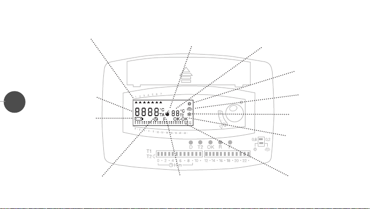
3. DISPLAY READINGS KEY
✲
Days of the week
On display: current
6
time and room
temperature
Low battery function
Operating
system
Reduced
temperature “T2”
(air conditioning)
Summer
Winter
(heating)
Antifrost
Proper set
confirmation
Operating program
activated
“Override” mode
activated
Time/temperature chart
of the activated program
Page 7
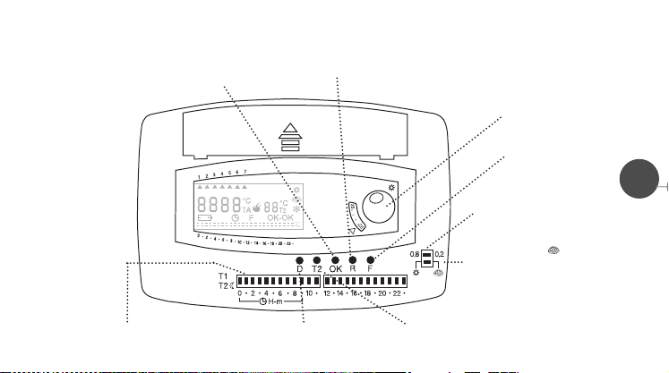
4. CHRONOTHERMOSTAT CONTROLS KEY
✲
Programming confirmation
Microswitches for current time
and operating setting
button
Reset button
Access to the program
and day change button
Reduced temperature “T2”
setting button
Knob for normal
temperature “T1” setting
Override
button
Differential selector
✲
) or winter ( )
Summer (
mode selector
7
Page 8

5. DIMENSIONS
88 mm
8
130 mm
1,5 mm
27 mm
60 mm
83,5 mm
Page 9
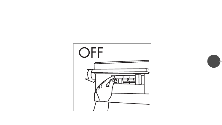
6. INSTALLATION AND CONNECTIONS
SAFETY INSTRUCTIONS
Before connecting the chronothermostat, make sure that the UNIT TO BE CONTROLLED (boiler, pump, air conditioning
system, etc.) is NOT CONNECTED from the electrical source. Make also sure that the power supply is the same as the one
specified inside the chronothermostat base (250V~ max).
9
Page 10
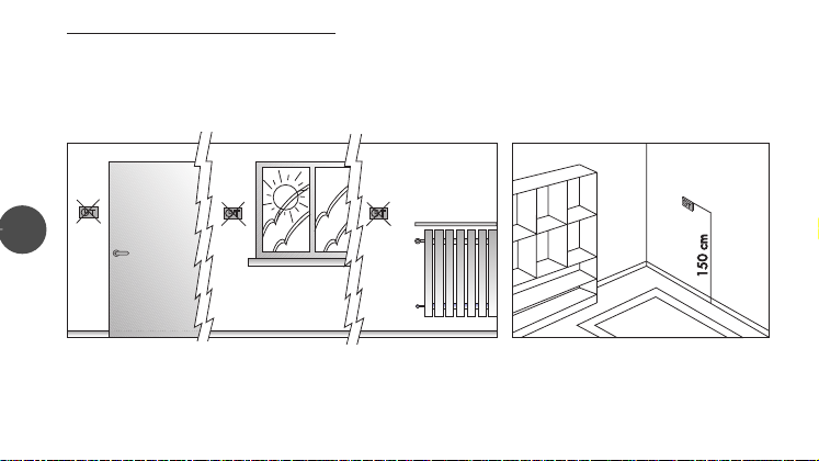
PLACEMENT OF THE CHRONOTHERMOSTAT
Place the chronothermostat away from heat sources (radiators, sunrays, kitchens) and away from doors / windows, etc.Install
the thermostat 1.5 Mt from the floor.
10
NO
YES
Page 11
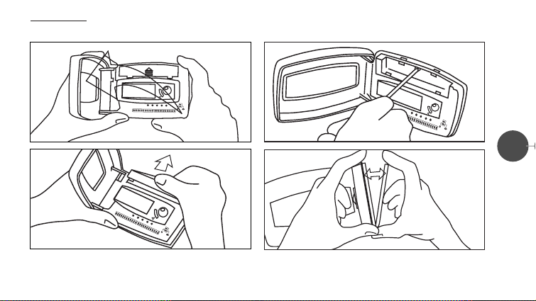
INSTALLA
TION
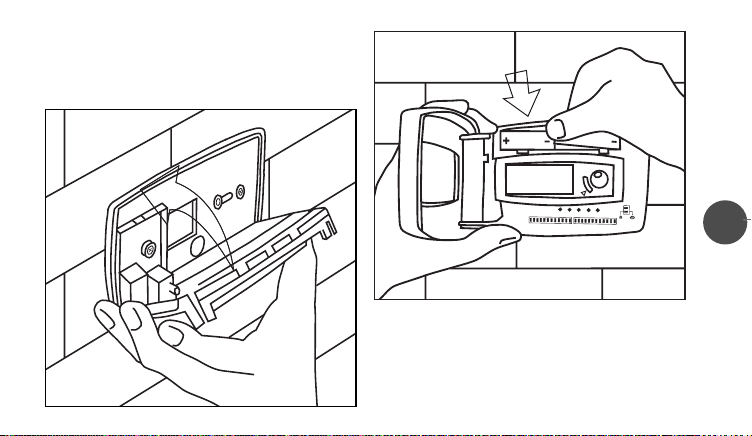
A) Open the front cover by lifting its left side
C) Remove the screw inside the battery compartment....
11
B) Remove the battery-compartment lid by pressing
along the arrow
...remove the base from the frontal part
of the chronothermostat....
Page 12
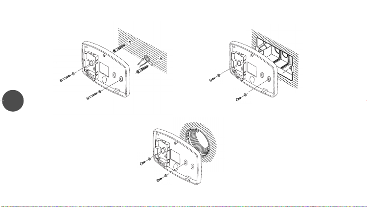
...then fix it to the wall according to installation requirements,
as shown in the figures.
12
Wall mounting
Mounting on round box.Distance
between center lines of 60 mm.
Mounting on three module buit-in std box.
Distance between center lines of 83,5 mm.
Page 13
D) Connect the wires to the terminals as per wiring diagram
(see next paragraph “wiring connections”), snap the unit
back to its base and tighten it with the provided screw.
13
E) Insert n° 2 1.5V alkaline batteries,type LR6
into the battery compartment, making sure that the proper
polarities are maintained.
N.B.Insert the first battery into the left side of the battery
compartment and the second one into the right side of the
compartment. Finally press on the second battery
so it fits properly.
Page 14
1
14
2
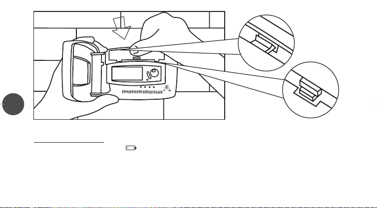
F) Close the battery compartment by matching the two top tabs in their slots (1) and then pressing on the bottom ones (2).
TTERY REPLACEMENT
BA
When the display shows a blinking “ ”(low batteries), the chronohermostat will still work properly for another month, after
that it will stop working and four “EEEE”will appear on the display (battery life:1 year).
To replace batteries, follow the steps A), B), E) and F) of the previous paragraph.
WARNING:
We recommend that the batteries be replaced on the heating system start-up.
Once the batteries are replaced, close the battery compartment lid, press the reset button (R) and reset the time as descri-
Page 15
bed in chapter 8 (clock setting).
12
U
N
L
3
T
WIRING CONNECTIONS
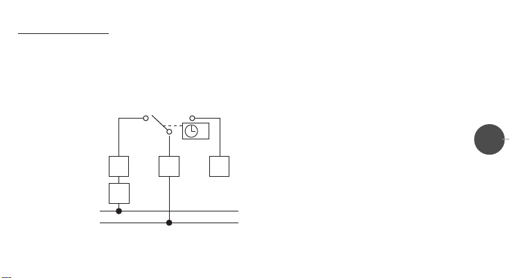
Connect the wires of UNIT TO BE CONTROLLED to terminal 1 and 2 of the chronothermostat (see wiring diagram).
WARNING:
We strongly recommend that, while installing the chronohermostat, all safety instructions and laws in force be strictly followed.
U= load
1= common contact
2= Normally Open contact
3= Normally Closed contact
15
Page 16
7. CHRONOTHERMOSTAT START-UP
After inserting the batteries, thus powering the chronothermostat, press the reset button (R) for 2-3 seconds with a pencil
point. All the available cursors and symbols will then be displayed for a few seconds (self-test). The chronother mostat is then
ready for CLOCK SETTING.
NOTE:
For a PROPER use of our product, from here on all the instruction paragraphs should be read in SEQUENCE, as per
manual!
8. CLOCK SETTING
16
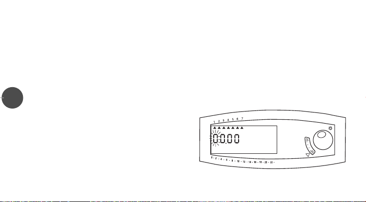
During this step, the display shows two hour-digits and two
minute-digits.The first digit on the left will blink (fig.1).
Switching down or up the micro-switches positioned under the
0 to 9”, will set the current time and day.
digits from “
The following example shows how to set Wednesday, 09:55:
• Switch the micro-switch “
(the second digit will blink) (fig.2).
• Switch the micro-switch “
display, thus completing the HOUR setting (the third digit will
0” to set the first digit on the display
9” to set the second digit on the
(fig.1)
Page 17
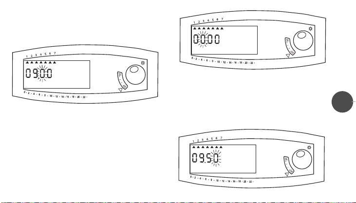
blink) (fig.3).
• Switch the micro-switch “
(the fourth digit will blink) (fig.4).
5” to set the third digit on the display
(fig.2)
(fig.3)
2=Tuesday …… 7=Sunday) (fig.5).
• Switch the micro-switch “
triangle” positioned under the third day of the week
(Wednesday “3”).The CLOCK SETTING is now completed.
3” to set on the display the “little
• Switch again the micro-switch “
display, thus completing the MINUTE setting (now the day-ofthe-week “little triangles” will be blinking: 1=Monday;
5” to set the four th digit on the
(fig.4)
17
Page 18
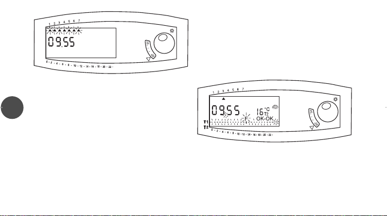
(fig.5)
- The CLOCK SETTING procedure may be start again at
any given time by pressing the reset button (R).
18
NOTE:
- When the CLOCK SETTING procedure is completed or in
case it is not completed within 10 minutes from start-up,
the chronothermostat will automatically start the “OVERRIDE” mode (shown by a blinking “F”, “T1” and the
“hours/temperature” chart on the display), assuring the
working at NORMAL temperature “T1”(“sun” knob) (fig.6).
(fig.6)
Page 19
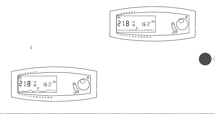
9. PROGRAM SETTING
Only after the clock is set, the chronothermostat “weekly” pro-
gram may be set, according to the following instructions:
• Press the
display, pointing at Monday (day #1) (fig.7).
• Move up the switches (position “
hours you want the temperature set with the “sun
(NORMAL temperature). On the contrary, lower the switches
(position “
CED temperature (
• Press
D button: the “little triangle” (▲) will blink on the
T1 ✲”) for the amount of
T2 ”), for the amount of hours you want the REDU-
T2 button).
OK to CONFIRM and DISPLAY Monday's setting (fig. 8). If changes are to be made, just set the new settings by
✲” knob
(fig.7)
micro-switches and then press
D button to switch to the next day: the “little triangle”
• Press the
▲) will blink on the display, pointing at Tuesday (day #2) (fig.
(
9).The “hours/temperature” chart for Tuesday and for any other
day of the week is set as Monday's.
OK to confirm them.
19
(fig.8)
Once completed the weekly setting, with the “little triangle”(
blinking and pointing at Sunday (day #7) (fig.10), press the
button to immediately end the “PROGRAM SETTING”mode.
▲)
D
Page 20
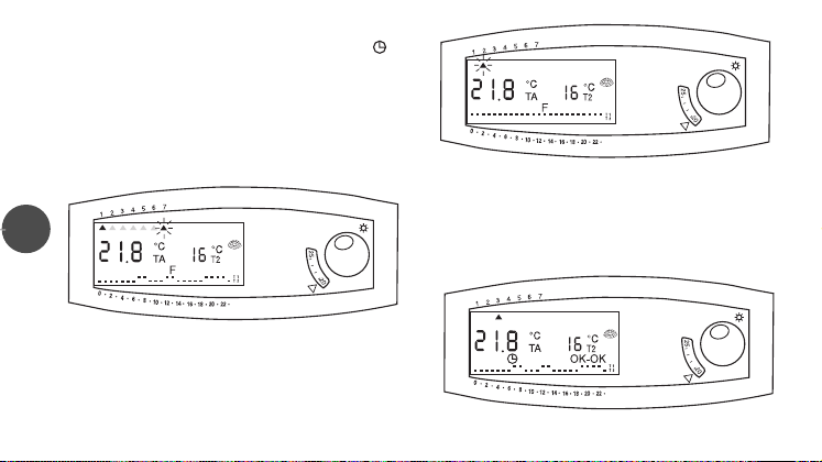
To ACTIVATE the program:
• Press the
the reading “OK-OK”are on display (fig.11).
NOTE:
- During “PROGRAM SETTING”if there are no operations
for about one minute, the unit will automatically go back
to the starting mode.
20
F button and check if the symbol “clock”( ) and
(fig.10)
(fig.9)
- When first installed, the weekly program is set on
“T1”NORMAL temperature for every hour of the day
(fig.11)
Page 21

10. TEMPERATURE SETTING
• To set the NORMAL temperature “T1”, simply turn the knob “sun ✲” until the little reference triangle on the front of the chro-
nothermostat points to the desired temperature on the temperature scale.
• REDUCED temperature “T2”may be chosen among 6°C, 14 °C, 1 6 °C or 18°C in winter mode ( ), and among 38°C, 30 °C,
28°C or 26°C in summer mode (
The chosen value of the REDUCED “T2”temperature will be on display.
NOTE:
If the reset button (R) is pressed, the REDUCED “T2” temperature values are automatically set on 16°C (winter mode)
and 26°C (summer mode).
✲), by pressing the T2 button in sequence (fig. 12).
21
Page 22
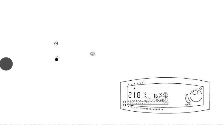
11. NORMAL OPERATION CONDITIONS
During “normal operation” the room temperature is displayed for 20 seconds (indicated by °C TA), alternating with the display
of current time for 10 seconds.
The following values are displayed as well (see chapter 3):
➞ The REDUCED temperature value (indicated by °C T2)
➞ The “hours/temperature” chart of the current day operational program, with its temperature levels T1 and T2
➞ The symbol “clock” ( )
➞ The reading “OK-OK”
➞ The symbol “sun” (✲) or the symbol “igloo”( ) for summer or winter operation
➞ The symbol “flame” ( ) indicating that the boiler or the air conditioner are on.
22
12. OVERRIDE MODE
This function allows the OVERRIDE of the running program so
that the chronothermostat keeps CONSTANTLY one of the two
temperature levels (NORMAL “T1” or REDUCED “T2”) or the
ANTIFROST mode (
To ACTIVATE the override mode:
once the F button to activate the ANTIFROST mode
• Press
(6°C)
twice the F button to activate the REDUCED tempera-
• Press
❄), factory pre-set at 6°C.
(fig.13)
Page 23

ture "T2" (6°C/14°C/16°C/18°C or 38°C/30°C/28°C/26°C).
three times the Fbutton to activate the NORMAL temperature “T1”(knob “sun ✲”)
• Press
When in “override”the letter “F”, the override symbol (
(fig.13).
NOTE:
Pressing the F button when the chronothermostat is in “override” at NORMAL temperature "T1", it takes the unit
back to normal operation under the ACTIVE program,indicated by the symbol “clock”( ) and by the reading “OK-
OK”on the display.
❄;T1 or T2) and the “hours/temperature” char t will blink on the display.
13. SUMMER/WINTER SETTING
The chronothermostat can be programmed for “summer”or “winter”operation, whether is connected to the air conditioner or
to the boiler.
• Switch the selector on the “sun”position (
mode or on the “igloo”position ( ) for “winter”mode (fig.14)
In both cases, either (
show which mode is on.
✲) or ( ) will appear on the display to
✲) for “summer”
23
Page 24

14. DIFFERENTIAL SETTING
The “differential”(∆t) is the difference between the room tem-
perature when the heating system “goes off”, and the room
temperature when it “comes on”again.
EXAMPLE:
Room temperature (heating system goes off) = 20°C
Room temperature (heating system comes on) = 19,8°C
∆t = 0,2°C
Two different differential values may be selected:
sable for water-circulating systems, for example “radiators”), or
24
0,8°C (advisable for air-circulating systems, for example “convectors”).
• Switch the selector on the desired position (fig.15).
0,2°C (advi-
15. KNOB LOCK
The “sun”knob, which sets the NORMAL temperature “T1”, may be locked, making it possible for the chronothermostat to be
used in public places, without anyone possibly changing the set temperature.
w to do it:
Ho
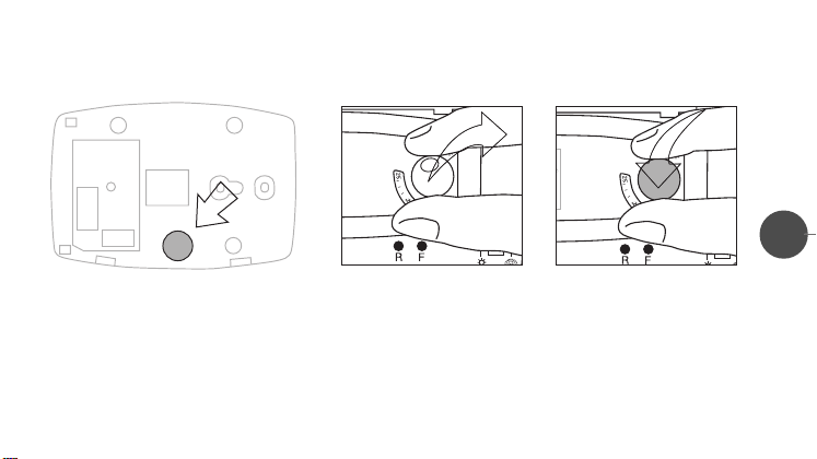
After opening the HOLE-CAP inside the base (fig.16), remove the knob from its seat and replace it with the HOLE-CAP itself
(figs.17 e 18).
Page 25
WARNING:
THE REPLACEMENT OF THE KNOB WITH THE HOLE-CAP MUST BE CARRIED OUT ONLY BY QUALIFIED PERSONNEL.
25
(fig.16)
(fig.17)
(fig.18)
16. UNIT RESET
Pressing the reset button (R) does not modify the active operation program, but it takes the clock back to zero and the “T2”
REDUCED temperature back to 16°C (winter mode) or 26°C (summer mode).
When the reset button (R) is pressed, the chronothermostat runs a “self-test”, lighting up all the segments on the display for a
few seconds.After that, it starts automatically the CLOCK SETTING mode, assuring (if it has not been programmed) a simple
room-thermostat operation (knob temperature “sun”).
Page 26
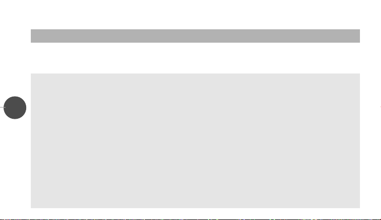
17. TROUBLESHOOTING
PROBLEM POSSIBILE CAUSE SOLUTION
The chronothermostat does not
turn on
The system does not start / does
not start at the preset time
26
1.Low batteries
2.Batteries improperly installed
3.False contact
4. Wrong wiring
5. Wrong program setting
6. OVERRIDE mode is on
7. Wrong summer/winter setting
8. Wrong current time setting
1.Replace batteries
2.Check for proper polarities
3.Press reset button (
4. Check the wiring of the load with
the terminals of the chronothermostat (#1 and #2)
5. Check the proper time setting in the
program (ex:micro-switch #7
activates the boiler from 7:00 to
7:59 a.m.)
6. Disable the mode at issue
7. Make sure that the display shows
the symbol “igloo”(if connected to a
boiler) or the symbol “sun”(if
connected to an air-conditioner)
8. Check the current time and, if
wrong, reset it
R)
Page 27
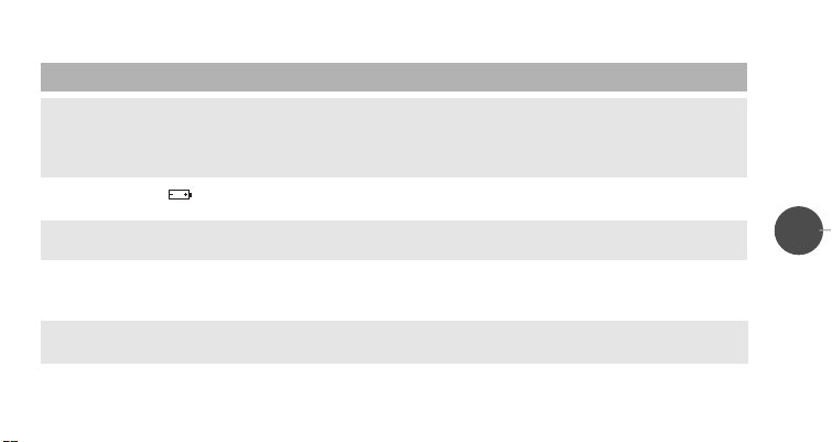
PROBLEM POSSIBILE CAUSE SOLUTION
The displayed room temperature
does not correspond to the real one
The display reads “ ”or “EEEE”
The front cover does not open
easily
After pressing the reset button (
the display does not light up
The chronothermostat has an
“irregular”behavior
NOTE: in case of repeated malfunctioning, please call service. Do not tamper, for any reason, with any part of the
chronothermostat.
9. Wrong location of the chronothermostat in the installation room
10.Air draft coming from the wire
conduit
11.Low batteries
12.Wrong opening procedure
13.The reset button (
R),
under the plastic
14.Non-alkaline batteries
R) got stuck
9. Follow the instructions in chapter 6,
paragraph “placement”.
10.Seal the conduit to prevent hot or
cold air drafts
11.Replace batteries and press the
reset button (
12.Lift the left side of the cover and
then open it towards the left
13.Release the button by using a
pencil point, so that it goes back to
its proper position
14.Use alkaline batteries, type LR6
R)
27
 Loading...