

Page 1

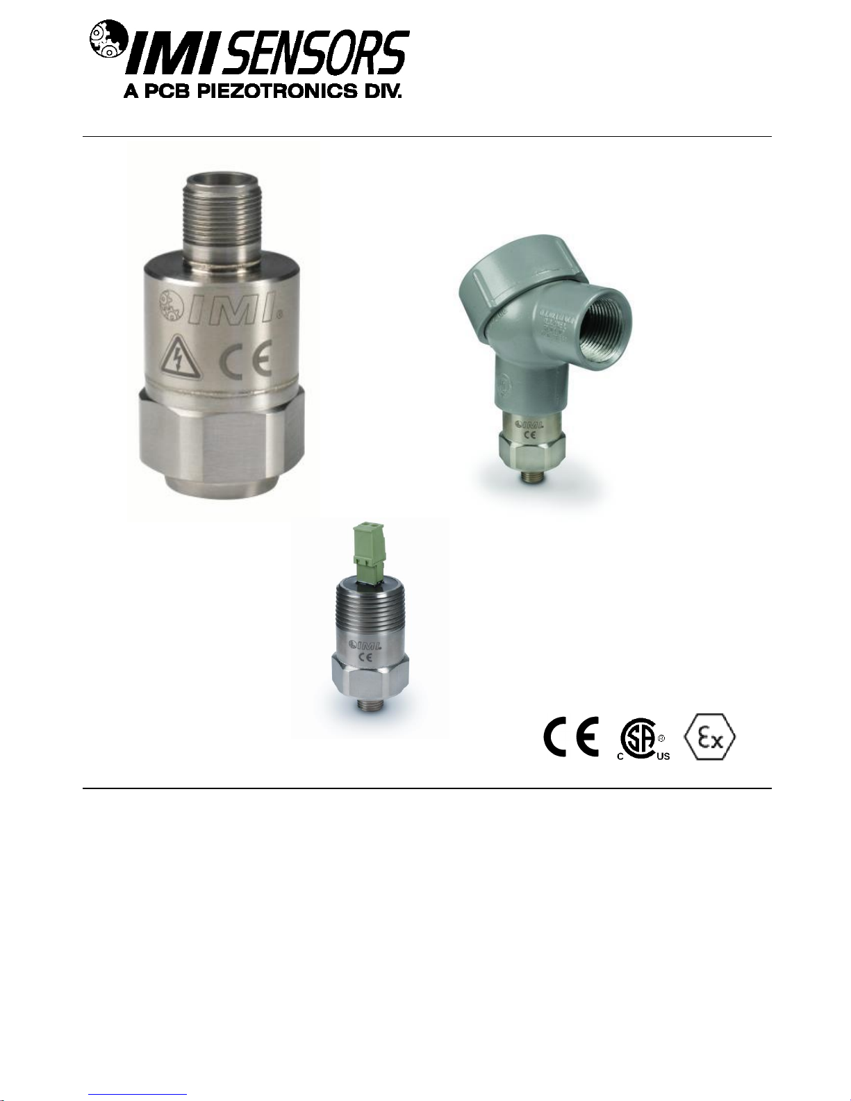
Model 686B0X-0003
Smart Vibration Switch
Installation and Operating Manual
For assistance with the operation of this product,
contact PCB Piezotronics, Inc.
Toll-free: 800-959-4464
24-hour SensorLine: 716-684-0001
Fax: 716-684-3823
E-mail: imi@pcb.com
Web: www.imi-sensors.com
Page 2

Service, Repair, and Return
Policies and Instructions
The information contained in this document supersedes all similar information that
may be found elsewhere in this manual.
Service – Due to the sophisticated
nature of the sensors and associated
instrumentation provided by PCB
Piezotronics, user servicing or repair is
not recommended and, if attempted,
may void the factory warranty. Routine
maintenance, such as the cleaning of
electrical connectors, housings, and
mounting surfaces with solutions and
techniques that will not harm the
physical material of construction, is
acceptable. Caution should be observed
to ensure that liquids are not permitted
to migrate into devices that are not
hermetically sealed. Such devices
should only be wiped with a dampened
cloth and never submerged or have
liquids poured upon them.
Repair – In the event that equipment
becomes damaged or ceases to
operate, arrangements should be made
to return the equipment to PCB
Piezotronics for repair. User servicing or
repair is not recommended and, if
attempted, may void the factory
warranty.
Calibration – Routine calibration of
sensors and associated instrumentation
is recommended as this helps build
confidence in measurement accuracy
and acquired data. Equipment
calibration cycles are typically
established by the users own quality
regimen. When in doubt about a
calibration cycle, a good “rule of thumb”
is to recalibrate on an annual basis. It is
also good practice to recalibrate after
exposure to any severe temperature
extreme, shock, load, or other
environmental influence, or prior to any
critical test.
PCB Piezotronics maintains an ISO9001 certified metrology laboratory and
offers calibration services, which are
accredited by A2LA to ISO/IEC 17025,
with full traceability to SI through
N.I.S.T. In addition to the normally
supplied calibration, special testing is
also available, such as: sensitivity at
elevated or cryogenic temperatures,
phase response, extended high or low
frequency response, extended range,
leak testing, hydrostatic pressure
testing, and others. For information on
standard recalibration services or
special testing, contact your local PCB
Piezotronics distributor, sales
representative, or factory customer
service representative.
Returning Equipment – Following
these procedures will ensure that your
returned materials are handled in the
most expedient manner. Before
returning any equipment to PCB
Piezotronics, contact your local
distributor, sales representative, or
factory customer service representative
to obtain a Return Warranty, Service,
Repair, and Return Policies and
Instructions Materials Authorization
(RMA) Number. This RMA number
should be clearly marked on the outside
of all package(s) and on the packing
Page 3

list(s) accompanying the shipment. A
detailed account of the nature of the
problem(s) being experienced with the
equipment should also be included
inside the package(s) containing any
returned materials.
A Purchase Order, included with the
returned materials, will expedite the
turn-around of serviced equipment. It is
recommended to include authorization
on the Purchase Order for PCB to
proceed with any repairs, as long as
they do not exceed 50% of the
replacement cost of the returned
item(s). PCB will provide a price
quotation or replacement
recommendation for any item whose
repair costs would exceed 50% of
replacement cost, or any item that is not
economically feasible to repair. For
routine calibration services, the
Purchase Order should include
authorization to proceed and return at
current pricing, which can be obtained
from a factory customer service
representative.
Contact Information – International
customers should direct all inquiries to
their local distributor or sales office. A
complete list of distributors and offices
can be found at www.pcb.com.
Customers within the United States may
contact their local sales representative
or a factory customer service
representative. A complete list of sales
representatives can be found at
www.pcb.com. Toll-free telephone
numbers for a factory customer service
representative, in the division
responsible for this product, can be
found on the title page at the front of this
manual. Our ship to address and
general contact numbers are:
PCB Piezotronics, Inc.
3425 Walden Ave.
Depew, NY14043 USA
Toll-free: (800) 828-8840
24-hour SensorLineSM: (716) 684-0001
Website: www.pcb.com
E-mail: info@pcb.com
Page 4

PCB工业监视和测量设备 - 中国RoHS2公布表
PCB Industrial Monitoring and Measuring Equipment - China RoHS 2 Disclosure Table
部件名称
有害物质
铅 (Pb)
汞
(Hg)
镉
(Cd)
六价铬 (Cr(VI))
多溴联苯 (PBB)
多溴二苯醚 (PBDE)
住房
O O O
O O O
PCB板
X O O
O O O
电气连接器
O O O
O O O
压电晶体
X O O
O O O
环氧
O O O
O O O
铁氟龙
O O O
O O O
电子
O O O
O O O
厚膜基板
O O X
O O O
电线
O O O
O O O
电缆
X O O
O O O
塑料
O O O
O O O
焊接
X O O
O O O
铜合金/黄铜
X O O
O O O
本表格依据 SJ/T 11364 的规定编制。
O: 表示该有害物质在该部件所有均质材料中的含量均在 GB/T 26572 规定的限量要求以下。
X: 表示该有害物质至少在该部件的某一均质材料中的含量超出 GB/T 26572 规定的限量要求。
铅是欧洲RoHS指令2011/65/ EU附件三和附件四目前由于允许的豁免。
CHINA RoHS COMPLIANCE
Page 5

Component Name
Hazardous Substances
Lead
(Pb)
Mercury
(Hg)
Cadmium
(Cd)
Chromium VI
Compounds
(Cr(VI))
Polybrominated
Biphenyls
(PBB)
Polybrominated
Diphenyl
Ethers (PBDE)
Housing O O O O O O
PCB Board
X O O O O
O
Electrical
Connectors
O O O O O
O
Piezoelectric
Crystals
X O O O O
O
Epoxy O O O O O O
Teflon O O O O O O
Electronics
O O O O O
O
Thick Film
Substrate
O O X O O
O
Wires O O O O O O
Cables X O O O O O
Plastic O O O O O O
Solder X O O O O O
Copper Alloy/Brass
X O O O O
O
This table is prepared in accordance with the provisions of SJ/T 11364.
O: Indicates that said hazardous substance contained in all of the homogeneous materials for this part is below the limit
requirement of GB/T 26572.
X: Indicates that said hazardous substance contained in at least one of the homogeneous materials for this part is above
the limit requirement of GB/T 26572.
Lead is present due to allowed exemption in Annex III or Annex IV of the European RoHS Directive 2011/65/EU.
DOCUMENT NUMBER: 21354
DOCUMENT REVISION: D
ECN: 46162
Page 6
SENSORS AND INSTRUMENTATION FOR MACHINE CONDITION MONITORING
686-Series Smart Vibration Switch
Operating Guide with Enclosed Warranty Information
3425 Walden Avenue, Depew, New York 14043-2495
Phone (716) 684-0003
Fax (716) 684-3823
Toll Free Line 1-800-959-4IMI
MANUAL NUMBER: 40112
MANUAL REVISION: D
ECN NUMBER: 47032
PAGE 1
Page 7

SENSORS AND INSTRUMENTATION FOR MACHINE CONDITION MONITORING
Table of Contents
Introduction ...................................................................................................................................................... Page 3
General Features
Operating Principles ........................................................................................................................................ Page 4
Benefits of Solid State Relays
Installation ........................................................................................................................................................ Page 5
Direct Adhesive Mount
Standard Stud Mount
Adhesive Stud Mount
Magnetic Mount
Wiring ............................................................................................................................................................... Page 9
Legend
Programming Software .................................................................................................................................. Page 21
Program Installation
Magnetically Adjustable Vibration Threshold (MAVT™) .............................................................................. Page 29
Factory-Programmed Ordering Guide ........................................................................................................... Page 30
Battery-Powered Signal Conditioner ............................................................................................................. Page 31
Calibration Cable ........................................................................................................................................... Page 31
Magnet Clip .................................................................................................................................................... Page 31
Cable Ordering Information ........................................................................................................................... Page 32
ESD Sensitivity .............................................................................................................................................. Page 33
Warranty, Service & Return Procedure ......................................................................................................... Page 34
Customer Service .......................................................................................................................................... Page 34
Indicating a High Level of Vibration in a Motor
Indicating High Levels of Vibration Simultaneously in Series (Such as Fan & Motor)
Constant Siren Alarming in the Event of High Vibration Levels
Two Switches in Parallel to Monitor Two Aces Simultaneously on Same Motor
Three Switches in Parallel to Monitor Three Motors Simultaneously
Automatic Machinery Shutdown Using an External Electromechanical Relay
Automatic Machinery Shutdown Using External Electromechanical Relay While Monitoring 2 Axes
Switch and External Latching for Automatic Machinery Shutdown
Both Alarm Siren and Automatic Machinery Shutdown Using Two Switches
Automatic Machinery Shutdown Based on Normally Open Solid State Relay
Automatic Machinery Shutdown of a Three Phase Electrical Motor Based on a N.O. Solid-State Relay
Running the Software
Programming Sections
Reading and Writing Parameters
Parameter Options
MAVT™ Procedure
PAGE 2
Page 8

SENSORS AND INSTRUMENTATION FOR MACHINE CONDITION MONITORING
Introduction
The 686-Series Smart Vibration Switch is a low-cost electronic vibration switch designed to monitor vibration
levels on rotating machinery (ie. fans and cooling towers) and trip an alarm or shut down machinery when a
specified vibration limit is exceeded. An onboard accelerometer with precision, microprocessor-controlled
electronics ensures reliable operation and accuracy. The switch contains a two-pin MIL connector for easy dropin replacement of mechanical vibration switches and a reliable solid state relay. Multiple units can be installed in a
loop configuration for economical installation and expanded protection of critical machinery. This versatile switch
can be used to replace more expensive electronic vibration switches where separate vibration output is not
required and to replace troublesome mechanical vibration switches.
Every Smart Switch is factory-programmed. See Page 28 for more information.
General Features
Fully USB-programmable from any PC (with optional USB Programmer Kit).
Hermetically-sealed, stainless steel housing for use in corrosive environments.
Imbedded piezoelectric accelerometer for improved accuracy and frequency response.
Small footprint and single ¼-28 stud mounting.
Solid state (AC/DC) relay.
Universal AC or DC power.
Magnetically Adjustable Vibration Threshold (MAVT™).
Connects with industry standard MIL-C-5015 connector or integral cable.
Programmable features
o Alarm threshold level
o Normally Open (NO) or Normally Closed (NC) relay
o Latching or non-latching relay
o Delays
Power on
Startup
Operational
o Residual vibration level
Intrinsically-safe versions available (EX prefix)
o CSA
PAGE 3
Page 9
SENSORS AND INSTRUMENTATION FOR MACHINE CONDITION MONITORING
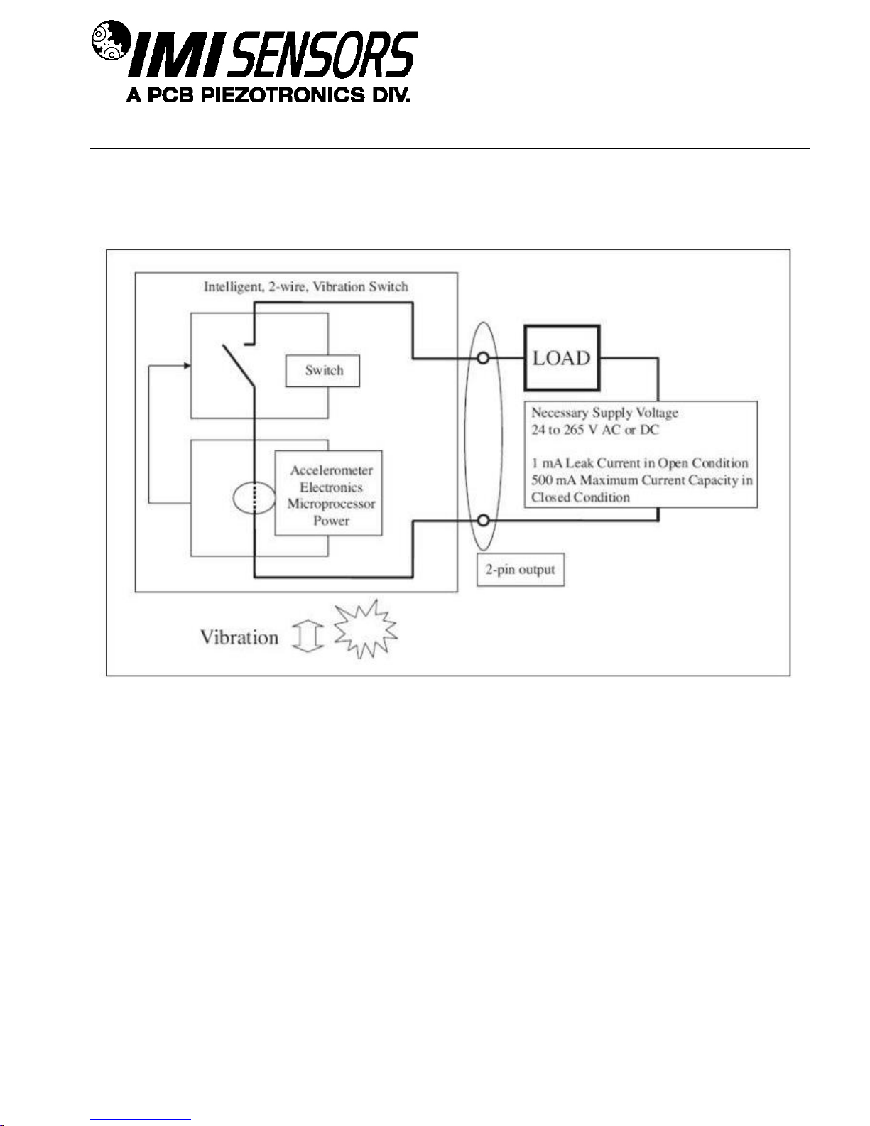
Operating Principles
The Smart Switch operates over just two wires. It installs in series with any load (ie. annunciator, PLC or relay
coil). To energize itself, the vibration switch scavenges power from the load’s power source. When the alarm
threshold is exceeded, the switch is activated and the load’s power circuit is completed to facilitate the desired
alarm or shutdown.
Benefits of Solid State Relays
A solid state relay is an electronic component that functions in the same way as an electromechanical relay, but
without any moving parts. A solid state relay offers the most reliable switch action, especially for vibration
applications where moving relay components run a greater risk of malfunction. They are purely electronic devices
composed of a low current control side and a high current load side for switching action.
Figure 1 – Block Diagram
PAGE 4
Page 10
SENSORS AND INSTRUMENTATION FOR MACHINE CONDITION MONITORING
Installation
When choosing a mounting method, consider closely the advantages and disadvantages of each technique.
Typical mounting types are stud, direct adhesive, adhesive mounting base and magnetic mounting base.
Note: For a complete list of product specifications, see the “Specification Sheet” and “Outline Drawing” at the end
of this Manual.
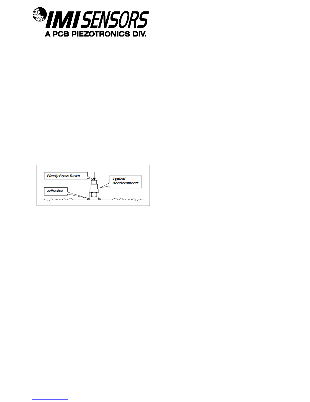
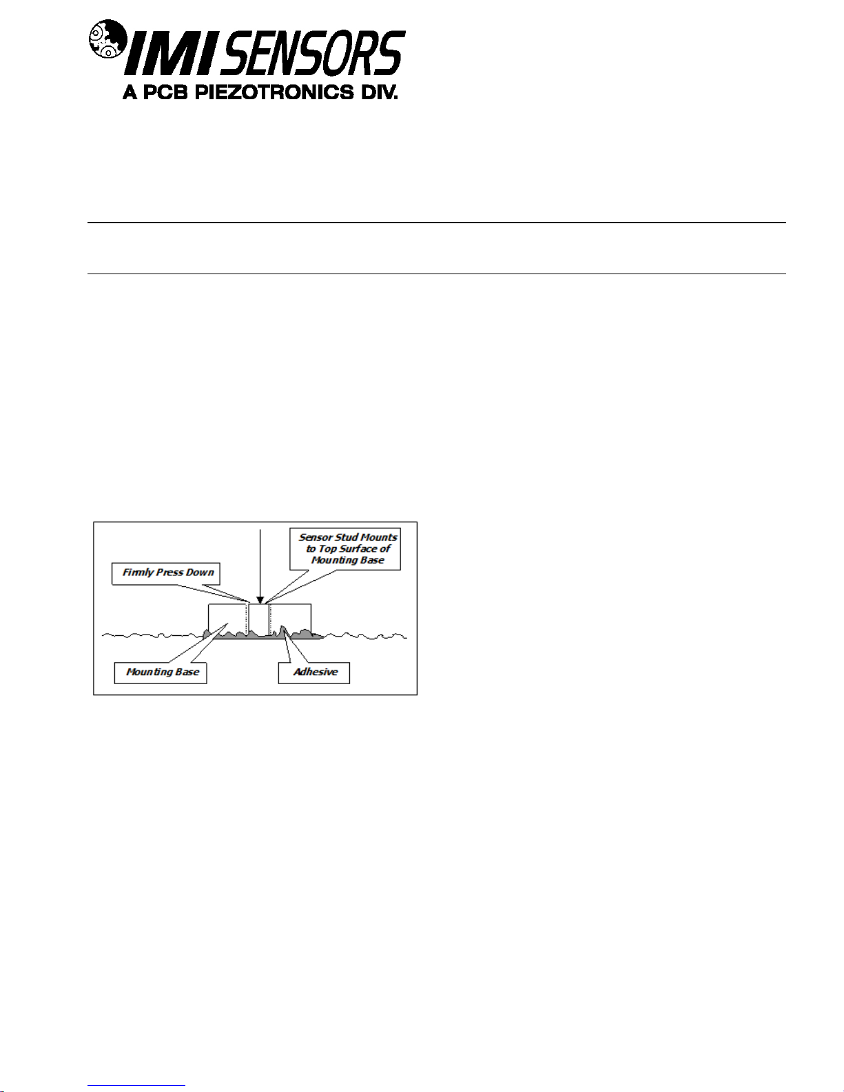
Direct Adhesive Mount Procedure
For restrictions of space or for convenience, most sensors (with the exception of integral stud models) can be
adhesive-mounted directly to the machine surface.
Step 1: Prepare a smooth, flat mounting surface. A minimum surface finish of 63 µin (0.00016 mm)
generally works best.
Step 2: Place a small portion of adhesive on the underside of the sensor. Firmly press down on the top of
the assembly to displace any adhesive. Be aware that excessive amounts of adhesive can make sensor
removal difficult.
Figure 2 – Direct Adhesive Mounting
PAGE 5
Page 11
SENSORS AND INSTRUMENTATION FOR MACHINE CONDITION MONITORING
¼-28 Stud
¼-28 Captive Screw
A (in)
0.250
0.250
B (in)
0.350
0.350
Torque (ft-lb)
2 to 5
2 to 5
Standard Stud Mount Procedure
This mounting technique requires smooth, flat contact surfaces for proper operation and is recommended for
permanent and/or secure installations. Stud mounting is also recommended when testing at high frequencies.
Note: Do not attempt mounting on curved, rough or uneven surfaces, as the potential for misalignment and
limited contact surface may significantly reduce the sensor’s upper operating frequency range.
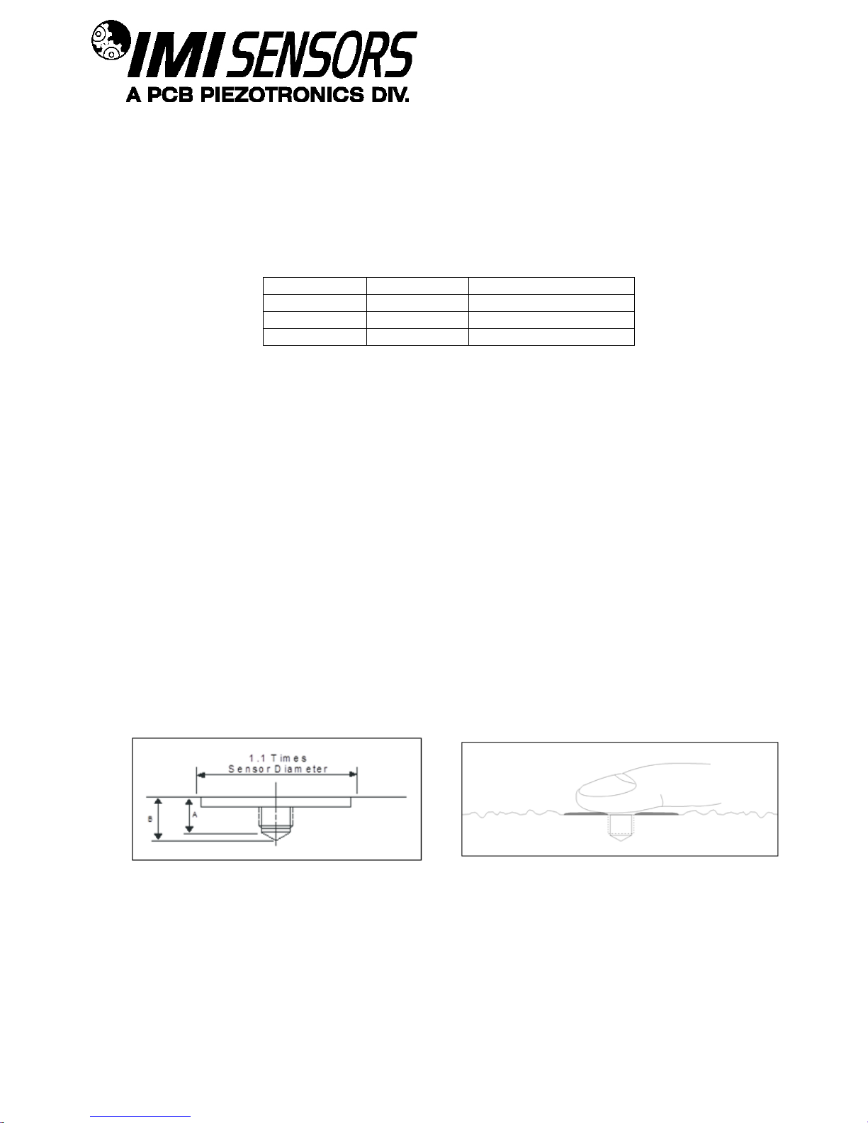
Step 1: First, prepare a smooth, flat mounting surface and then drill and tap a mounting hole in the center
of this area. A precision-machined mounting surface with a minimum finish of 63 µin (0.00016 mm) is
recommended. (If it is not possible to properly prepare the machine surface, consider using an adhesive
mounting pad as a possible alternative.) Inspect the area, checking that there are no burrs or other
foreign particles interfering with the contact surface.
Step 2: Wipe clean the mounting surface and spread on a light film of grease, oil or similar coupling fluid
prior to installation. Adding a coupling fluid improves vibration transmissibility by filling small voids in the
mounting surface and increasing the mounting stiffness. For semi-permanent mounting, substitute epoxy
or another type of adhesive.
Step 3: Hand-tighten the sensor/mounting stud to the machine, and then secure the sensor with a torque
wrench to the mounting surface by applying the recommended mounting torque (see enclosed
specification data sheet for proper mounting torque). It is important to use a torque wrench during this
step. Under-torqueing the sensor may not adequately couple the device; over-torqueing may result in
stud failure and possibly permanent damage.
Figure 3 – Mounting Surface Preparation Figure 4 – Mounting Surface Lubrication
PAGE 6
Page 12
SENSORS AND INSTRUMENTATION FOR MACHINE CONDITION MONITORING
Adhesive Stud Mount Procedure
Adhesive mounting is often used for temporary installation or when the machine surface cannot be adequately
prepared for stud mounting. Adhesives like hot glue or wax work well for temporary mounts; two-part epoxies and
quick-bonding gels provide a more permanent mount.
Note: Adhesively mounted sensors often exhibit a reduction in high-frequency range. Generally, smooth
surfaces and stiff adhesives provide the best frequency response. Contact the factory for recommended epoxies.
This method involves attaching a base to the machine surface, then securing the sensor to the base. This allows
for easy removal of the accelerometer.
Step 1: Prepare a smooth, flat mounting surface. A minimum surface finish of 63 µin (0.00016 mm)
generally works best.
Step 2: Stud-mount the sensor to the appropriate adhesive mounting base according to the guidelines set
forth in Steps 2 and 3 of the Standard Stud Mount Procedure.
Step 3: Place a small portion of adhesive on the underside of the mounting base. Firmly press down on
the assembly to displace any extra adhesive remaining under the base.
Figure 5 – Adhesive Installation of Mounting Base
PAGE 7
Page 13
SENSORS AND INSTRUMENTATION FOR MACHINE CONDITION MONITORING
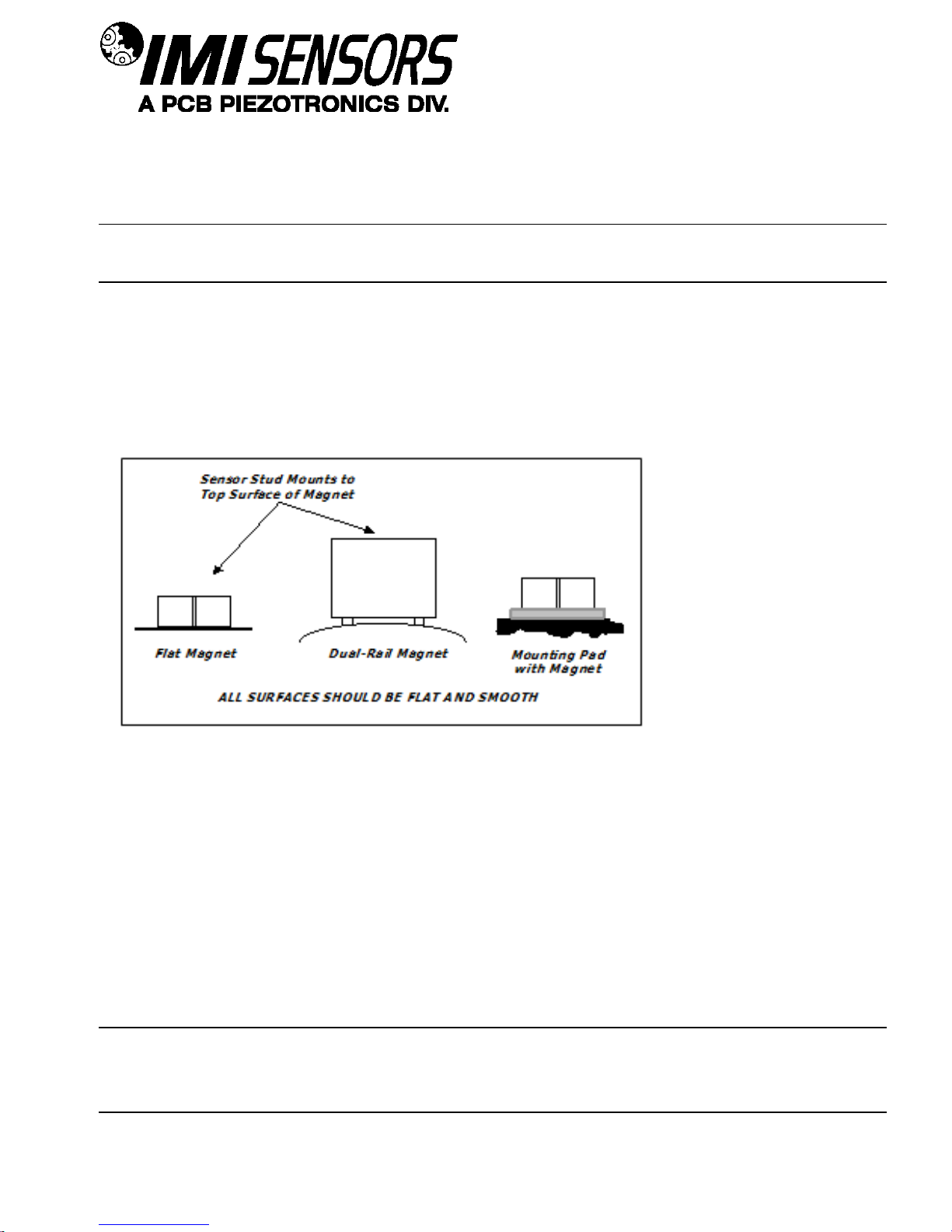
Magnetic Mount Procedure
Magnetic mounting provides a convenient means for making portable measurements and is commonly used for
machinery monitoring and other portable or trending applications.
Note: The correct magnet choice and an adequately prepared mounting surface are critical for obtaining reliable
measurements, especially at high frequencies. Poor installations can cause as much as a 50% drop in the sensor
frequency range.
Not every magnet is suitable for all applications. For example, rare earth magnets are commonly used because
of their high strength. Flat magnets work well on smooth, flat surfaces, while dual-rail magnets are required for
curved surfaces. In the case of non-magnetic or rough surfaces, it is recommended that the user first weld, epoxy
or otherwise adhere a steel mounting pad to the test surface. This provides a smooth and repeatable location for
mounting.
Figure 6 – Magnet Types
Step 1: After choosing the correct magnet, inspect the unit to verify that the mounting surfaces are flat
and smooth.
Step 2: Stud-mount the accelerometer to the appropriate magnet according to the guidelines set forth in
Steps 2 and 3 of the Standard Stud Mount Procedure.
Step 3: Prepare a smooth, flat mounting surface. A minimum surface finish of 63 µin [0.00016 mm]
generally works best. After cleaning the surface and checking for burrs, wipe on a light film of silicone
grease, machine oil or similar-type coupling fluid.
Step 4: Mount the magnet/sensor assembly to the prepared test surface by gently “rocking” or “sliding” it
into place.
Note: Magnetically mounting accelerometers carelessly has the potential to generate very high (and very
damaging) g levels. To prevent damage, install the assembly gently. If unsure, please contact the factory for
assistance.
PAGE 8
Page 14

SENSORS AND INSTRUMENTATION FOR MACHINE CONDITION MONITORING
Attribute
Omron Model Number
MJN2C-
AC120
MJN2C-
AC240
MJN2C-
DC12
MJN2C-
DC24
MJN2C-
DC110
Contact Form
2 Form C (DPDT)
Relay Rated Resistive Load
10 A @ 240 VAC/28 VDC
Service Life- Electrical
(Min @Rated Loads)
100,000 operations “average”
Relay Max Resistive
Switching Capacity
2400 VA, 280
W
240 VAC
12 VDC
24 VDC
110 VDC
Coil Nominal Voltage
120 VAC
1.2 W
Coil Power Consumption
1.7 VA
Coil Type
Non-Latching
Seal Type
Unsealed
Termination Style
Socket Mount
Operating Temperature Range
-45 to +60 C
with no icing or condensation
-45 to +70 C
with no icing or condensation
Dielectric Strength
(AC for 1 min)
2500 VAC
Approved Standards
UL, CSA
Wiring
On the following pages are eleven different wiring scenarios for the Smart Switch. The wiring legend below is
applicable to all wiring diagrams.
Figure 7 – Wiring Diagrams Legend
For those wiring scenarios that suggest the use of an external electromechanical relay, IMI suggests Omron
general purpose relays as listed below. Visit www.omron.com for more information.
PAGE 9
Page 15

10
SENSORS AND INSTRUMENTATION FOR MACHINE CONDITION MONITORING
Indicating a High Level of Vibration in a Motor
Figures 8 and 9 – Indicating a High Level of Vibration in a Motor
Pushing the Start pushbutton closes the M contacts and starts the motor. If the start-up delay option for the
switch is enabled, the Smart Switch will not trip regardless of the vibration level during the specified delay time.
After this delay, the vibration switch will be activated. If the vibration level exceeds the alarm threshold for a time
period greater than the specified operational delay time, the relay will trip. This action will close the contact to the
pilot lamp.
Since the NL (non-latching) option is specified, the pilot lamp will illuminate only while alarm threshold is
exceeded. Should the vibration level drop below the alarm threshold value (based also on the specified
hysteresis), the pilot lamp will turn off.
Page 16

11
SENSORS AND INSTRUMENTATION FOR MACHINE CONDITION MONITORING
Indicating High Levels of Vibration Simultaneously in Series (Such as Fan & Motor)
Figures 10 and 11 – Indicating High Levels of Vibration Simultaneously in Series (Such as Fan & Motor)
The Smart Switches are hooked up in series and installed on the two most loaded bearings across the coupling in
the horizontal direction. Pushing the Start pushbutton closes the M contacts and starts the motor and fan. If the
start-up delay option for the switches is enabled, the Smart Switches will not trip during the specified startup delay
time, regardless of the vibration level. After this delay, the switch relays will be activated if the vibration level on
both machines exceeds the alarm threshold for a period greater than the specified operation delay time. This
action will close the contact to the pilot lamp.
Since the NL (non-latching) option is specified, the pilot lamp will illuminate only while set threshold on both
machines is exceeded. Should the vibration level for one or both of the machines drop below the threshold value
(based also on the specified hysteresis), the pilot lamp will turn off.
Page 17

12
SENSORS AND INSTRUMENTATION FOR MACHINE CONDITION MONITORING
Constant Siren Alarming in the Event of High Vibration Levels
Figure 12 – Constant Siren Alarming in the Event of High Vibration Levels
The Smart Switch is hooked up for automatic constant siren alarming when the alarm threshold level is exceeded.
Pushing the Start pushbutton closes the M contact and starts the motor. If the start-up delay option for the
switches is enabled, the Smart Switches will not trip during the specified startup delay time, regardless of the
vibration level. After this delay, the switch relay will be activated if the vibration level exceeds the alarm threshold
for a period greater than the specified operational delay time. This action will close the contact to the alarm siren
and activate it.
Since the LA (latching) option is specified, the alarm siren will be constantly energized after this high vibration
event, even if the vibration level should drop below the alarm threshold. The Reset pushbutton should be
engaged to de-energize the alarm siren and return the system to its original monitoring condition.
Page 18

13
SENSORS AND INSTRUMENTATION FOR MACHINE CONDITION MONITORING
Using Two Switches in Parallel to Monitor Two Axes Simultaneously on Same Motor
Figures 13 and 14 – Using Two Switches in Parallel to Monitor Two Axes Simultaneously on Same Motor
The Smart Switches are hooked up in parallel and installed on the motor in horizontal and vertical directions.
Pushing the Start pushbutton closes the M contact and starts the motor. If the start-up delay option for the
switches is enabled, then during the specified startup delay time, the switches will not trip regardless of the
vibration level. After this delay, the alarm siren will be activated if either of the switches experiences a vibration
level over the alarm threshold lasting greater than the specified operation delay time.
Since the NL (non-latching) option is specified, the alarm siren will sound while alarm threshold on one or both
switches is exceeded. Should the vibration level for both switches drop below the alarm threshold value (based
also on the specified hysteresis), the alarm siren will turn off.
Page 19

14
SENSORS AND INSTRUMENTATION FOR MACHINE CONDITION MONITORING
The three Smart Switches are hooked up
in parallel and installed on each motor in
the horizontal direction. This provides an
economical solution for monitoring a group
of machinery while only having to run one
cable. Pushing any Start pushbutton will
close the corresponding M contact and
start the motor. If the start-up delay option
for the switches is enabled, then during the
specified startup delay time, the switches
will not trip; regardless of the vibration
level. After this delay, the pilot lamp will be
illuminated if any of the switches
experience a vibration level over the alarm
threshold value lasting greater than the
specified operational delay time.
Since the NL (non-latching) option is
specified, the pilot lamp will illuminate while
alarm threshold on any of the switches is
exceeded. When the vibration level for all
switches drops below their alarm threshold
value (based also on the specified
hysteresis), the pilot lamp will turn off.
Using Three Switches in Parallel to Monitor Three Motors Simultaneously
Figures 15 and 16 – Using Three Switches in Parallel to Monitor Three Motors Simultaneously
Page 20

15
SENSORS AND INSTRUMENTATION FOR MACHINE CONDITION MONITORING
Automatic Machinery Shutdown Using an External Electromechanical Relay
Figures 17 and 18 – Automatic Machinery Shutdown Using an External Electromechanical Relay
The Smart Switch is hooked up for automatic motor shutdown when the alarm threshold level is exceeded. The
switch should be mounted in the horizontal direction on the bearing carrying the most load. Pushing the Start
pushbutton closes the M contact and starts the motor. If the start-up delay option for the switches is enabled, the
Smart Switches will not trip during the specified startup delay time, regardless of the vibration level. After this
delay, the switch relay will be activated if the vibration level exceeds the alarm threshold for a period greater than
the specified operational delay time. This action will close the contact and send a voltage to the RL relay coil.
This will open the RL1 and close the RL2 contacts, shut down the motor, and light the pilot lamp.
Since the LA (latching) option is enabled, the RL coil will be constantly energized after this event; even if the
vibration level drops below the alarm threshold value after shutdown. The Reset pushbutton should be pushed to
reset the switch and close the RL1 and RL2 contacts before restarting the motor.
Page 21

16
SENSORS AND INSTRUMENTATION FOR MACHINE CONDITION MONITORING
Automatic Machinery Shutdown Using an External Electromechanical Relay While Monitoring 2 Axes
Figures 19 and 20 – Automatic Machinery Shutdown Using an External Electromechanical Relay While
Monitoring 2 Axes
The Smart Switches are hooked up in parallel for automatic motor shutdown when the alarm threshold level is
exceeded on either switch. The switches should be mounted in the horizontal and vertical direction at the bearing
carrying the most load. Pushing the Start pushbutton closes the M contact and starts the motor. If the start-up
delay option for the switches is enabled, the Smart Switches will not trip during the specified startup delay time,
regardless of the vibration level. After this delay, the switch relay will be activated if the vibration level of either
switch exceeds the alarm threshold for a period greater than the specified operational delay time. This action will
close the contact and send a voltage to the RL relay coil. This will open the RL contacts and shut down the
motor.
Since the LA (latching) option is specified, the RL coil will be constantly energized after this event; even if the
vibration level drops below the alarm threshold value after shutdown. The Reset pushbutton should be pushed to
reset the switch and close the RL contacts before restarting the motor.
Page 22

17
SENSORS AND INSTRUMENTATION FOR MACHINE CONDITION MONITORING
Using the Switch and External Latching for Automatic Machinery Shutdown
Figure 21 – Using the Switch and External Latching for Automatic Machinery Shutdown
The Smart Switches are hooked up for automatic motor shutdown in case of high vibration levels on critical
machinery. Since RL2 contacts are normally closed, pushing the Start pushbutton closes the M contact and
starts the motor. If the start-up delay option for the switches is enabled, the Smart Switches will not trip during the
specified startup delay time, regardless of the vibration level. After this delay, the switch relay will be activated if
the vibration level of either switch exceeds the alarm threshold for a period greater than the specified operational
delay time. This action will close the contacts and send a voltage to the RL relay coil. This will open the RL2
contacts and shut down the motor.
Since the LA (latching) option is specified, the RL1 contacts are used for external latching. Closing of RL1
provides constant coil energizing after the shutdown event. Therefore, when the vibration level drops below the
alarm threshold level after shutdown, the closed RL1 contacts still energize the RL coil and keep RL2 in the open
position. The Reset pushbutton should be pushed to reset the 2-wire switch, close the RL2 contacts and open
the RL1 contacts before restarting the motor.
Page 23

18
SENSORS AND INSTRUMENTATION FOR MACHINE CONDITION MONITORING
Both Alarm Siren and Automatic Machinery Shutdown Using Two Switches
Figure 22 – Both Alarm Siren and Automatic Machinery Shutdown Using Two Switches
The Smart Switches are hooked up for providing alarm siren and automatic motor shutdown when the alarm
threshold levels are exceeded. To accomplish this, the two switches have two different threshold values; one for
alarm and one for shutdown. Pushing the Start pushbutton closes the M contact, and since RL2 contacts are
normally closed, starts the motor. If the start-up delay option for the switch is enabled, the switch will not trip
regardless of the vibration level during the specified delay time. After this delay, if the vibration level exceeds the
alarm threshold for the alarm switch, it will be activated and apply a voltage to the alarm siren. Since the NL (nonlatching) option is specified for this switch, the alarm siren will be energized until the vibration level falls below the
alarm threshold value (based also on the specified hysteresis). If the vibration level exceeds the shutdown alarm
threshold, the second vibration switch will be activated and apply a voltage to the RL relay coil. This will open the
RL contacts and shut down the motor. Since the LA (latching) option is specified, the RL coil will be constantly
energized after this event; even though the vibration level will drop below the alarm threshold value after
shutdown. The Reset pushbutton should be pushed to reset the switch and close the RL contacts before
restarting the motor.
Page 24

19
SENSORS AND INSTRUMENTATION FOR MACHINE CONDITION MONITORING
Automatic Machinery Shutdown Based on Normally Open Solid-State Relay
Figure 23 – Automatic Machinery Shutdown Based on Normally Open Solid-State Relay
The Smart Switch is hooked up to provide automatic motor shutdown when the alarm threshold level is exceeded.
Pushing the Start pushbutton closes the M contact, and since the switch is Normally Closed, the solid state relay
will be energized and the RL contacts will be closed. This will start the motor. If the start-up delay option is
enabled, the switch will not trip regardless of the vibration level during the specified delay time. After this delay, if
the vibration level exceeds the alarm threshold, it will be activated, thereby opening its contacts and de-energizing
the solid state relay input. This will open the RL contacts and shut down the motor. Since the LA (latching) option
is specified, the solid state relay input will be constantly de-energized after this event even if the vibration level
drops below the alarm threshold value after shutdown. The Reset pushbutton should be pushed to reset the
switch and close the RL contacts before restarting the motor.
Page 25

20
SENSORS AND INSTRUMENTATION FOR MACHINE CONDITION MONITORING
Automatic Machinery Shutdown of Three-Phase Electrical Motor Based on a N.O. Solid State Relay
Figure 24 – Automatic Machinery Shutdown of 3-Phase Electrical Motor Based on a N.O. Solid State Relay
The Smart Switch is hooked up to provide automatic motor shutdown when the alarm threshold level is exceeded
using a normally open three channel solid state relay. Since the Smart Switch is normally closed, closing the
Start Switch will energize the solid state relay. This will cause the RL1, RL2, and RL3 contacts to close and start
the motor. If the start-up delay option for the switch is enabled, the switch will not trip regardless of the vibration
level during the specified delay time. After this delay, if the vibration level exceeds the alarm threshold, it will be
activated, thereby opening its contacts and de-energizing the solid state relay input. This will open the RL1, RL2,
& RL3 contacts and shut down the motor. Since the LA (latching) option is specified, the solid state relay input
will be constantly de-energized after this event; even if the vibration level drops below the alarm threshold value
after shutdown. The Reset pushbutton should be pushed to reset the switch and close the RL1, RL2, & RL3
contacts before restarting the motor. This will start the motor immediately without using the Start pushbutton.
Page 26

21
SENSORS AND INSTRUMENTATION FOR MACHINE CONDITION MONITORING
Programming Software
The Smart Switch can be user-programmed with the optional Model 600A29 Programming Kit. The kit includes
USB programmer cable/dongle (Model 070A100), software (Model EE225), terminal block/integral cable adapter
(Model 042M17) and magnet clip (Model 080A214). The software can also be downloaded from IMI’s website,
www.pcb.com. This software must be installed prior to connecting the Smart Switch to the computer using the
USB programmer cable. The software includes both the drivers and user interface needed for programming the
Smart Switch. During initial installation, you may need administrative rights for the computer in order to install the
drivers. Once installed, administrative rights are not required for use.
Figure 25 – Model 600A29 USB Programmer Kit
Program Installation
Installing the Software and USB Driver: Insert the software CD provided into the CD drive. The software will start
the installation automatically if your PC is set to auto-install applications. If not, browse the CD and click on
Setup.exe to start the installation process. The default installation directory is C:\PCB\EE225. It is recommended
to use the default setting.
The installer will first install the software and then the WinUSB device driver. This device driver is required for the
programmer software to communicate with the 070A100 USB programmer cable included in the programmer kit.
The following screens will be displayed when the installer starts. Click the Next button to proceed from step to
step.
Figure 26 – Install Location Screen
Page 27

22
SENSORS AND INSTRUMENTATION FOR MACHINE CONDITION MONITORING
Figure 27 – National Instruments Software License Agreement
Figure 28 – Installation Verification Screen
Figure 29 – Installation Complete Screen
Page 28

23
SENSORS AND INSTRUMENTATION FOR MACHINE CONDITION MONITORING
After the software completes, the USB driver installer will start automatically. The initial USB installer will look
similar to the one below.
Figure 30 – WinUSB Driver Installation Screen
The drivers will now be properly installed and you should get the following screen. Click “Finish”. The software is
now ready to use.
Figure 31 – WinUSB Driver Installation Complete Screen
Page 29

24
SENSORS AND INSTRUMENTATION FOR MACHINE CONDITION MONITORING
Running the Software
Connect the USB programmer cable to the Smart Switch. Hold a magnet to the indicated MAVT™ point on the
Smart Switch. Wait about 2 seconds. While keeping the magnet against the Smart Switch, connect the USB
programmer cable to a USB port on the PC. Run the software from the Start | All Programs | PCB EE225
Software menu item.
Initially the screen will appear as in Error! Reference source not found. with a yellow bar and status indicating
‘Initializing…’ followed by the message: “Connecting to USB Dongle…”.
Figure 32 – Software While Connecting to USB Programmer Cable
Once the connection is made the bar at the top of the screen will turn green and the status will indicate “USB
Connection Success - Select a device”. If the software and USB programmer cable fail to connect, remove and
reinsert the USB programmer cable.
Figure 33 – Software After Connecting to USB Programmer Cable
Page 30

25
SENSORS AND INSTRUMENTATION FOR MACHINE CONDITION MONITORING
To select a device, click on the Device Select pull down menu and select the device you’d like to program. In this
case, select 686.
Once a product is selected, the software will prompt you to confirm connection of the sensor to the PC using the
USB programmer cable. Click OK to proceed.
Figure 34 – Device Selection
While the software is establishing communication with the sensor, the status will display ‘Checking Status…’ and
the colored indicator box next to the status will alternate between red and yellow. This will take approximately 15
seconds. Once communication is established, the indicator box will turn green and the software will read the
sensor’s current settings and data. The fields presented in the main body of the screen will be specific to the
selected sensor.
Figure 35 – Sensor Connection Screen
Page 31

SENSORS AND INSTRUMENTATION FOR MACHINE CONDITION MONITORING
Programming Sections
The screen has two sections:
Actual 686 Settings – This section shows the settings currently programed in the sensor.
686 Settings to Write – This section shows the options for programming the sensor.
Figure 36 – Typical Smart Switch Screen After Successful Parameter Read
Reading and Writing Parameters
Reading Parameters - To read the current sensor settings, click the Read Parameters button. This
operation takes approximately 45 seconds to complete.
Transferring Actual Settings to Settings to Write Field - Use the ‘>>>’ button to transfer all Actual Settings
to the Settings to Write fields.
Writing Parameters- Select the appropriate mode and enter any pertinent parameter information. Click the
Set Parameters button. This causes the settings to be sent to the sensor and then read back and
displayed in the Actual 686 Settings.
Figure 37 – Transferring Actual Settings to Settings to Write Field
PAGE 26
Page 32

SENSORS AND INSTRUMENTATION FOR MACHINE CONDITION MONITORING
Parameter
Description
Acceptable Value(s)
Actual Vibration
Actual vibration (ips pk) being sensed by the switch at time
when Read Parameters button is clicked.
N/A
MAVT™
Capability to determine and set the alarm threshold value
automatically by the Smart Switch based on the actual
vibration level measured by it. For more information about
the MAVT™ feature, see page 16.
Enabled
Disabled
Alarm Threshold
Vibration level at which the relay will change state.
0.25- 5.0 ips pk
6.35-127 mm/s pk
Hysteresis
Percentage that actual vibration must fall below the alarm
threshold in order for a non-latching relay to automatically
reset itself. Hysteresis prevents a relay from continually
changing states when the vibration level is hovering around
the alarm threshold level.
3%
6%
10%
Relay Contacts-
Normal State
State in which the relay stays when not tripped.
Normally Open
Normally Closed
Relay Contacts-
Reset State
How the relay operates once actual vibration falls below the
alarm threshold.
Latching: Relay to latch or stay in the alarm state
until manually reset regardless of the vibration level.
Non-Latching Relay automatically resets once the
vibration level falls below the alarm threshold
(hysteresis) level.
Latching
Non-Latching
Power On Delay
Specified time period immediately after power is applied to
the switch during which the relay will not trip regardless of
the vibration level. Prevents a relay trip during high transient
vibration levels that may occur during a normal machine
startup.
3 sec
20 sec
Operation Delay
Specified time period for which actual vibration must
constantly exceed the Alarm Threshold before the relay
changes state. Prevents a relay trip as a result of a short
transient spike in vibration level that may not even be
caused by a machine fault.
1-60 sec
Startup Delay-
Status
Specified time period immediately after power is applied to
the equipment being monitored during which the relay will
not trip regardless of vibration level.
Enabled
Disabled
Startup Delay-
Time Period
Time period during which vibration is ignored.
1-60 sec
1-30 min
Startup Delay-
Startup Alarm Threshold
Maximum vibration ignored during the time period.
Calculated as a multiple of the Alarm Threshold.
2x
4x
8x
Blocked (All vibration)
Startup Delay-
Residual Vibration Level
Minimum vibration level that, once surpassed at equipment
startup, triggers the countdown of the Startup Delay Time
Period.
Dependent
1-40% of Threshold
Independent
0- Alarm Threshold
Parameter Options
The software presents one read-only parameter (Actual Vibration) and several parameters that can be
programmed to optimize performance of the Smart Switch. At any point during the programming process, the
values can be changed between imperial and metric measurements by clicking the Units dropdown in the top
navigation menu and then selecting the appropriate measurement type.
PAGE 27
Page 33

SENSORS AND INSTRUMENTATION FOR MACHINE CONDITION MONITORING
Last Alphanumeric Character
1 2 3 4 X
Parameter
MAVT™
Enabled
Custom,
Customer-
Specific
Configuration
Alarm Threshold 0.60 ips
Hysteresis
6%
Relay Contacts-
Normal State
Normally
Open
Normally
Closed
Normally
Open
Normally
Closed
Relay Contacts-
Reset State
Latching
Latching
Non-Latching
Non-Latching
Power On Delay
3 sec
Operation Delay
6 sec
Startup Delay-
Status
Enabled
Startup Delay-
Time Period
3 sec
Startup Delay-
Startup Alarm Threshold
2x
Startup Delay-
Residual Vibration Level
Dependent
5% of Threshold
Unless otherwise specified, the Smart Switch comes from the factory with a set of default parameters. The
specific set of parameters depends on the last alphanumeric character in the model number.
PAGE 28
Page 34

SENSORS AND INSTRUMENTATION FOR MACHINE CONDITION MONITORING
Magnetically Adjustable Vibration Threshold (MAVT™)
Magnetically Adjustable Vibration Threshold (MAVT™) is a Smart Switch selectable feature via USB
programming. This unique capability allows the alarm threshold value to be determined and set automatically by
the Smart Switch based on the actual vibration level being measured by it. This convenient feature permits any
machine to be protected by a vibration switch within seconds without knowing anything about its vibration levels.
The Smart Switch has no accessible mechanical adjustments (ie. screw pots or DIP switches) that are found on
other style electronic vibration switches. However, when the MAVT™ option is selected, the hermetically-sealed
switch becomes adjustable through magnetic actuation. By touching a specified location on the housing with a
strong permanent magnet for 2 seconds, an internal microprocessor is actuated that initiates the test sequence.
Note: The magnet clip (Model 080A214) is a supplied accessory when the Smart Switch is ordered from the
factory with the optional 600A29 USB Switch Programmer Kit.
Figure 38 – Magnet Clip
MAVT™ Procedure
Be absolutely sure you do not have the switch connected to the machine’s trip circuit during this procedure as the
trip relay is activated several times during the procedure and will cause the machine to shut down and turn on
several times. This could cause damage to your machinery.
1. Mount the Smart Switch on the machine that the switch will monitor. Be sure that the machine is
operating in a steady state condition. If it is not operating, turn the machine on and allow enough time for
the vibration level to normalize before going to the next step.
2. Connect the switch to the power supply using an appropriate cable. Since the Smart Switch operates off
universal power, any power supply that outputs 24-240 VDC or 24-240 VAC, 50/60 Hz will work. A
simple 24V power supply/signal conditioner (Model 480C02) will also work well and has the added
advantage of visually indicating when the calibration process has been completed via its built-in meter.
Allow 30 seconds for the switch to power up.
3. Touch the permanent magnet to the target on the side of the switch for approximately 2 seconds to
initiate the process.
4. The alarm threshold calibration process takes approximately 30 seconds. (The amount of time needed
varies based on the difference between the previous and new alarm threshold values.) During this
process, the unit will measure the average vibration amplitude, set the alarm threshold value to two times
this average value and store this value in a non-volatile memory. The relay contacts open and close
repeatedly during this process.
5. Disconnect the Smart Switch from the power supply.
6. The switch can now be permanently installed on the machine for protection.
PAGE 29
Page 35

SENSORS AND INSTRUMENTATION FOR MACHINE CONDITION MONITORING
Factory Programmed Ordering Guide
Figure 39 – Ordering Guide
PAGE 30
Page 36

SENSORS AND INSTRUMENTATION FOR MACHINE CONDITION MONITORING
Battery-Powered Signal Conditioner
Power supply/signal conditioner (Model 480C02) is for use with the Smart Switch when determining the alarm
threshold level using the MAVT™ feature. The built-in meter indicates when the process is complete. See
www.pcb.com for product details.
Figure 40 – Battery Powered Signal Conditioner
Calibration Cable
The calibration cable (Model 052BR010AC) is a 10 foot, twisted-pair, shielded cable with a 2-Pin MIL type
connector terminating to a BNC plug for use with 480C02 power supply and Smart Switch.
Figure 41 – Calibration Cable
Magnet Clip
The magnet clip (Model 080A214) is supplied as part of the optional 600A29 USB Programmer Kit or can be
ordered separately for use with the MAVT™.
Figures 42 and 43 – Magnet Clip with and without Smart Switch
PAGE 31
Page 37

SENSORS AND INSTRUMENTATION FOR MACHINE CONDITION MONITORING
Cable Ordering Information
Go to www.pcb.com for complete information on cables.
IMI Part Number: 052 BR 010 BZ
Cable Model Series
052 Polyurethane, Shielded, Twisted Pair
048 Armored Polyurethane, Shielded, Twisted Pair
Switch Connector Type
AE 2 socket MIL type with environmental boot
BP 2 socket MIL type high temp with strain relief
BR 2 socket MIL type molded composite
BQ 2 socket MIL type molded composite, right angle
Cable Length
010 10 feet
020 20 feet
030 30 feet
040 40 feet
050 50 feet
XXX Any length
Cable termination
BZ Blunt Cut
(Consult factory for additional options)
PAGE 32
Page 38

SENSORS AND INSTRUMENTATION FOR MACHINE CONDITION MONITORING
Warning 1 – ESD sensitivity
personnel. This product is intended for use by qualified personnel who recognize shock hazards and are familiar
with the safety precautions required to avoid injury.
Warning 2 – ESD sensitivity
This equipment is designed with user safety in mind; however, the protection provided by the equipment may be
impaired if the equipment is used in a manner not specified by PCB Piezotronics, Inc.
Caution 1 – ESD sensitivity
Cables can kill your equipment. High voltage electrostatic discharge (ESD) can damage electrical devices.
Similar to a capacitor, a cable can hold a charge caused by triboelectric transfer, such as that which occurs in the
following:
Laying on and moving across a rug,
Any movement through air,
The action of rolling out a cable, and/or
Contact with a non-grounded person.
The PCB solution for product safety:
Connect the cables only with the AC power off.
Temporarily “short” the end of the cable before attaching it to any signal input or output.
Caution 2 – ESD sensitivity
ESD considerations should be made prior to performing any internal adjustments on the equipment. Any
piece of electronic equipment is vulnerable to ESD when opened for adjustments. Internal adjustments should
therefore be done ONLY at an ESD-safe work area. Many products have ESD protection, but the level of
protection may be exceeded by extremely high voltage.
PAGE 33
Page 39

SENSORS AND INSTRUMENTATION FOR MACHINE CONDITION MONITORING
Warranty
IMI instrumentation is warranted against defective material and workmanship for 1 year unless otherwise
expressly specified. Damage to instruments caused by incorrect power or misapplication, is not covered by
warranty. If there are any questions regarding power, intended application, or general usage, please consult with
your local sales contact or distributor. Batteries and other expendable hardware items are not covered by
warranty.
Service
Because of the sophisticated nature of IMI instrumentation, field repair is typically NOT recommended and may
void any warranty. If factory service is required, return the instrumentation according to the “Return Procedure”
stated below. A repair and/or replacement quotation will be provided prior to servicing at no charge. Before
returning the unit, please consult a factory IMI applications engineer concerning the situation as certain problems
can often be corrected with simple on-site procedures.
Return procedure
To expedite returned instrumentation, contact a factory IMI applications engineer for a RETURN MATERIAL
AUTHORIZATION (RMA) NUMBER. Please have information available such as model and serial number. Also,
to insure efficient service, provide a written description of the symptoms and problems with the equipment to a
local sales representative or distributor, or contact IMI if none are located in your area.
Customers outside the U.S. should consult their local IMI distributor for information on returning equipment. For
exceptions, please contact the International Sales department at IMI to request shipping instructions and an RMA.
For assistance, please call (716) 684-0003, or fax us at (716) 684-3823. You may also receive assistance via email at imi@pcb.com or visit our web site at www.pcb.com.
Customer Service
IMI, a division of PCB Piezotronics, guarantees Total Customer Satisfaction. If, at any time, for any reason, you
are not completely satisfied with any IMI product, IMI will repair, replace, or exchange it at no charge. You may
also choose to have your purchase price refunded.
IMI offers to all customers, at no charge, 24-hour phone support. This service makes product or application
support available to our customers, day or night, seven days a week. When unforeseen problems or emergency
situations arise, call the IMI Hot Line at (716) 684-0003, and an application specialist will assist you.
PAGE 34
Page 40

Model Number
686B0X
SMART VIBRATION SWITCH
Revision: B
ECN #: 39883
[2]
Performance
ENGLISH
SI
Alarm Threshold(± 10 %)
0.25 to 5 in/sec pk
4.5 to 90 mm/s rms
Frequency Range(± 3 dB)
420 to 60 kcpm
7 to 1000 Hz
Hysteresis(% < Alarm Threshold)
3; 6; or 10 %
3; 6; or 10 %
[1]
Residual Vibration Level(Reference)
Dependent or Independent Dependent or Independent
[1]
Residual Vibration Level(% Alarm Threshold)
1 to 40 %
1 to 40 %
[1]
MAVT(Sets Alarm Threshold to 2X actual vibration) Enabled or Disabled
Enabled or Disabled
[1]
Transverse Sensitivity
<7 %
<7 %
Power On Delay(± 1 sec)
3 or 20 sec
3 or 20 sec
[1]
Startup Delay(± 1 sec or 1 min)(Time)
1 to 60 sec or 1 to 30 min 1 to 60 sec or 1 to 30 min
[1]
Startup Delay(x Alarm Threshold)
x2; x4; x8; Blocked
x2; x4; x8; Blocked
[1]
Startup Delay(Active)
Enabled or Disabled
Enabled or Disabled
[1]
Operational Delay(± 1 sec)
1 to 60 sec
1 to 60 sec
[1]
Relay(Type)
SPST, Form A or B
MOSFET
SPST, Form A or B
MOSFET
Relay(Latching)
Latching / Non-Latching Latching / Non-Latching
Relay(Contacts)
Normally Open / Closed Normally Open / Closed
Environmental
Temperature Range(Operating)
-40 to 185 °F
-40 to 85 °C
Temperature Range(Storage)
-40 to 257 °F
-40 to 125 °C
Overload Limit(Shock)
5000 g pk
49,050 m/s² pk
Enclosure Rating
IP68
IP68
Electrical
Power Required
24 to 240 V DC/AC 50/60 Hz 24 to 240 V DC/AC 50/60 Hz
Current Rating(Relay Closed)
500 mA
500 mA
Leak Current(Relay Open)
≤ 1 mA
≤ 1 mA
Electrical Isolation(Case)
>108 Ohm
>108 Ohm
Physical
Size (Hex x Height)
1.25 in x 2.6 in
1.25 in x 66 mm
Weight
5.2 oz
148 gm
Mounting Torque
3 to 5 ft-lb
4 to 7 Nm
Mounting Thread
1/4-28 Female
1/4-28 Female
Sensing Element(Internal)
Piezoelectric Accelerometer Piezoelectric Accelerometer
Housing Material
Stainless Steel
Stainless Steel
Sealing
Welded Hermetic
Welded Hermetic
Electrical Connector
2-Pin MIL-C-5015
2-Pin MIL-C-5015
Electrical Connection Position
Top
Top
All specifications are at room temperature unless otherwise specified.
In the interest of constant product improvement, we reserve the right to change specifications without
notice.
OPTIONAL VERSIONS
Optional versions have identical specifications and accessories as listed for the standard model
except where noted below. More than one option may be used.
EX
- Hazardous Area Approval- contact factory for specific approvals
Current Rating(Relay Closed)
100 mA
100 mA
Hazardous Area Approval
Cl I, Div 2, Groups A, B, C, D;
Ex nL IICT3, AEx nA IICT3
Cl I, Div 2, Groups A, B, C, D;
Ex nL IICT3, AEx nA IICT3
Power Required
10 to 30 VDC
10 to 30 VDC
Relay(Capacity)
10 to 30 VDC, 100 mA
10 to 30 VDC, 100 mA
M
- Metric Mount
Supplied Accessory : Model M081A61 Mounting Stud 1/4
-
28 to M6 X 1 (1)
NOTES:
[1]
USB Programmable
-
See configuration sheet supplied with switch for exact setting.
[2]
See PCB Declaration of Conformance PS023 or PS060 for details.
SUPPLIED ACCESSORIES:
Model 081A41 Mounting stud 1/4-28 socket head set screw brass tip stainless steel 5/8" long
(1)
Entered: AP Engineer: do Sales: EGY
Approved: BAM
Spec Number:
Date: 9/4/2012 Date: 9/4/2012 Date: 9/4/2012 Date: 9/4/2012
40110
3425 Walden Avenue, Depew, NY 14043
Phone: 800-959-4464
Fax: 716-684-3823
E-Mail: imi@pcb.com
Page 41

PCB Piezotronics Inc. claims proprietary rights in
the information disclosed hereon. Neither it nor any
reproduction thereof will be disclosed to others
without the written consent of PCB Piezotronics Inc.
1
2
REVISIONS
REV DESCRIPTION DIN
B REVISED TITLE 46960
1
1
1
0
4
1.25 [31.8] HEX
B B
PINS ARE BI-POLAR
1.34 [34.1]
MIL-C-5015 CONNECTOR
2 PIN RECEPTACLE
2.6 [66]
1.240 [31.50]
1.87 [47.5]
.80 [20.3]
.20 [5.1]
A A
.920 [23.37]
1/4-28 UNF - 2B .21
[1/4-28 UNF - 2B
5.3]
UNLESS OTHERWISE SPECIFIED TOLERANCES ARE:
DIMENSIONS IN INCHES
DECIMALS XX ±.03
ANGLES 2 DEGREES
XXX ±.010
FILLETS AND RADII
.003 - .005
DIMENSIONS IN MILLIMETERS
[ IN BRACKETS ]
DECIMALS X ± 0.8
ANGLES 2 DEGREES
XX ± 0.25
FILLETS AND RADII
0.07 - 0.13
2
DRAWN CHECKED ENGINEER
TITLE
KRM
7/11/17
JDM
7/11/17
OUTLINE DRAWING
MODEL 686B & 686C SERIES
VIBRATION SWITCH
BAM
7/11/17
3425 WALDEN AVE. DEPEW, NY 14043
(716) 684-0001 E-MAIL: sales@pcb.com
IDENT. NO.
52681
SCALE: SHEET
FULL
40111
1 OF 1
DWG. NO.
CODE
1
 Loading...