

Page 1

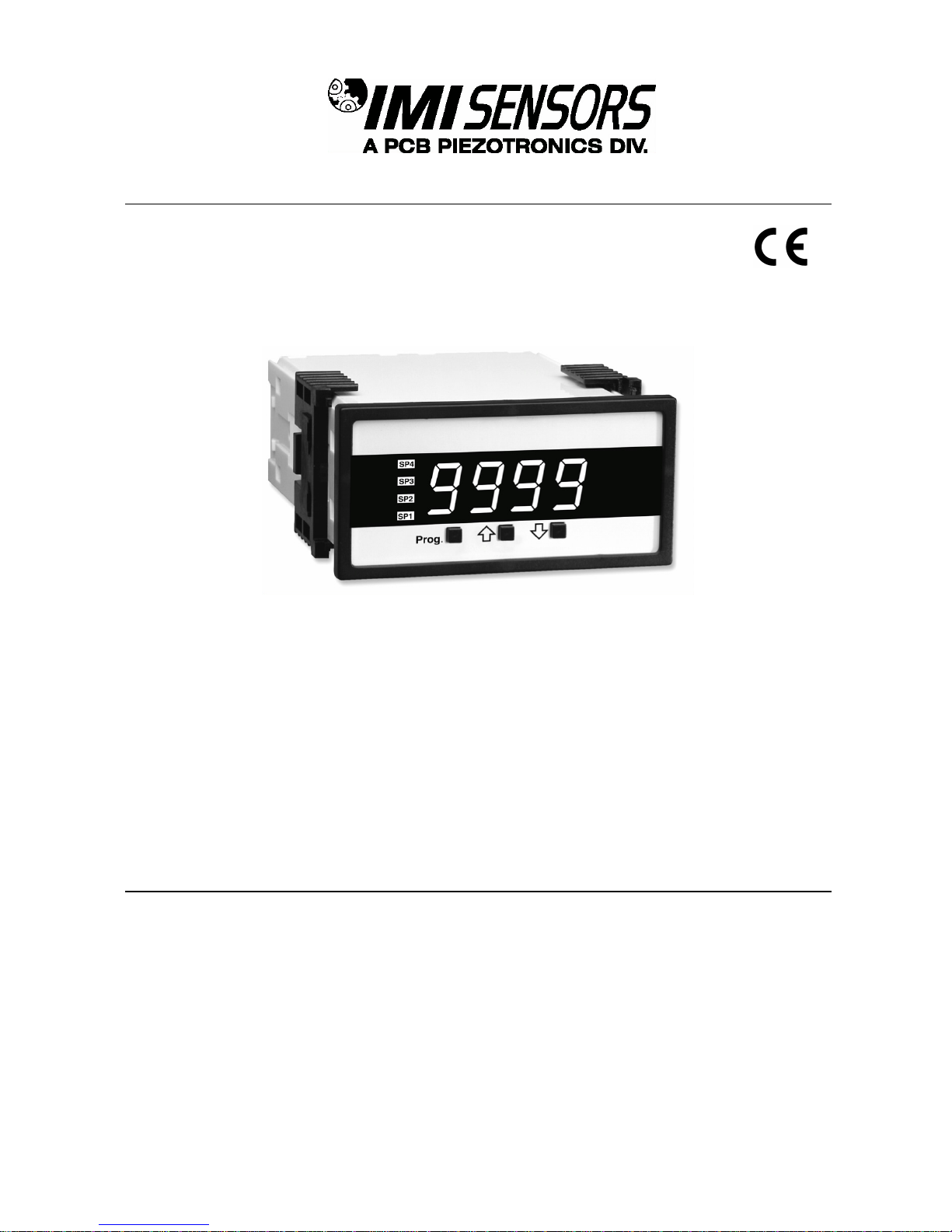
Model 683A111001
Indicator/Controller (for use w/ ICP® sensors)
Installation and Operating Manual
For assistance with the operation of this product,
contact PCB Piezotronics, Inc.
Toll-free: 800-959-4464
24-hour SensorLine: 716-684-0001
Fax: 716-684-3823
E-mail: imi@pcb.com
Web: www.imi-sensors.com
Page 2

Service, Repair, and Return
Policies and Instructions
The information contained in this document supersedes all similar information that
may be found elsewhere in this manual.
Service – Due to the sophisticated
nature of the sensors and associated
instrumentation provided by PCB
Piezotronics, user servicing or repair is
not recommended and, if attempted,
may void the factory warranty. Routine
maintenance, such as the cleaning of
electrical connectors, housings, and
mounting surfaces with solutions and
techniques that will not harm the
physical material of construction, is
acceptable. Caution should be observed
to ensure that liquids are not permitted
to migrate into devices that are not
hermetically sealed. Such devices
should only be wiped with a dampened
cloth and never submerged or have
liquids poured upon them.
Repair – In the event that equipment
becomes damaged or ceases to
operate, arrangements should be made
to return the equipment to PCB
Piezotronics for repair. User servicing or
repair is not recommended and, if
attempted, may void the factory
warranty.
Calibration – Routine calibration of
sensors and associated instrumentation
is recommended as this helps build
confidence in measurement accuracy
and acquired data. Equipment
calibration cycles are typically
established by the users own quality
regimen. When in doubt about a
calibration cycle, a good “rule of thumb”
is to recalibrate on an annual basis. It is
also good practice to recalibrate after
exposure to any severe temperature
extreme, shock, load, or other
environmental influence, or prior to any
critical test.
PCB Piezotronics maintains an ISO9001 certified metrology laboratory and
offers calibration services, which are
accredited by A2LA to ISO/IEC 17025,
with full traceability to SI through
N.I.S.T. In addition to the normally
supplied calibration, special testing is
also available, such as: sensitivity at
elevated or cryogenic temperatures,
phase response, extended high or low
frequency response, extended range,
leak testing, hydrostatic pressure
testing, and others. For information on
standard recalibration services or
special testing, contact your local PCB
Piezotronics distributor, sales
representative, or factory customer
service representative.
Returning Equipment – Following
these procedures will ensure that your
returned materials are handled in the
most expedient manner. Before
returning any equipment to PCB
Piezotronics, contact your local
distributor, sales representative, or
factory customer service representative
to obtain a Return Warranty, Service,
Repair, and Return Policies and
Instructions Materials Authorization
(RMA) Number. This RMA number
should be clearly marked on the outside
of all package(s) and on the packing
Page 3

list(s) accompanying the shipment. A
detailed account of the nature of the
problem(s) being experienced with the
equipment should also be included
inside the package(s) containing any
returned materials.
A Purchase Order, included with the
returned materials, will expedite the
turn-around of serviced equipment. It is
recommended to include authorization
on the Purchase Order for PCB to
proceed with any repairs, as long as
they do not exceed 50% of the
replacement cost of the returned
item(s). PCB will provide a price
quotation or replacement
recommendation for any item whose
repair costs would exceed 50% of
replacement cost, or any item that is not
economically feasible to repair. For
routine calibration services, the
Purchase Order should include
authorization to proceed and return at
current pricing, which can be obtained
from a factory customer service
representative.
Contact Information – International
customers should direct all inquiries to
their local distributor or sales office. A
complete list of distributors and offices
can be found at www.pcb.com.
Customers within the United States may
contact their local sales representative
or a factory customer service
representative. A complete list of sales
representatives can be found at
www.pcb.com. Toll-free telephone
numbers for a factory customer service
representative, in the division
responsible for this product, can be
found on the title page at the front of this
manual. Our ship to address and
general contact numbers are:
PCB Piezotronics, Inc.
3425 Walden Ave.
Depew, NY14043 USA
Toll-free: (800) 828-8840
24-hour SensorLineSM: (716) 684-0001
Website: www.pcb.com
E-mail: info@pcb.com
Page 4

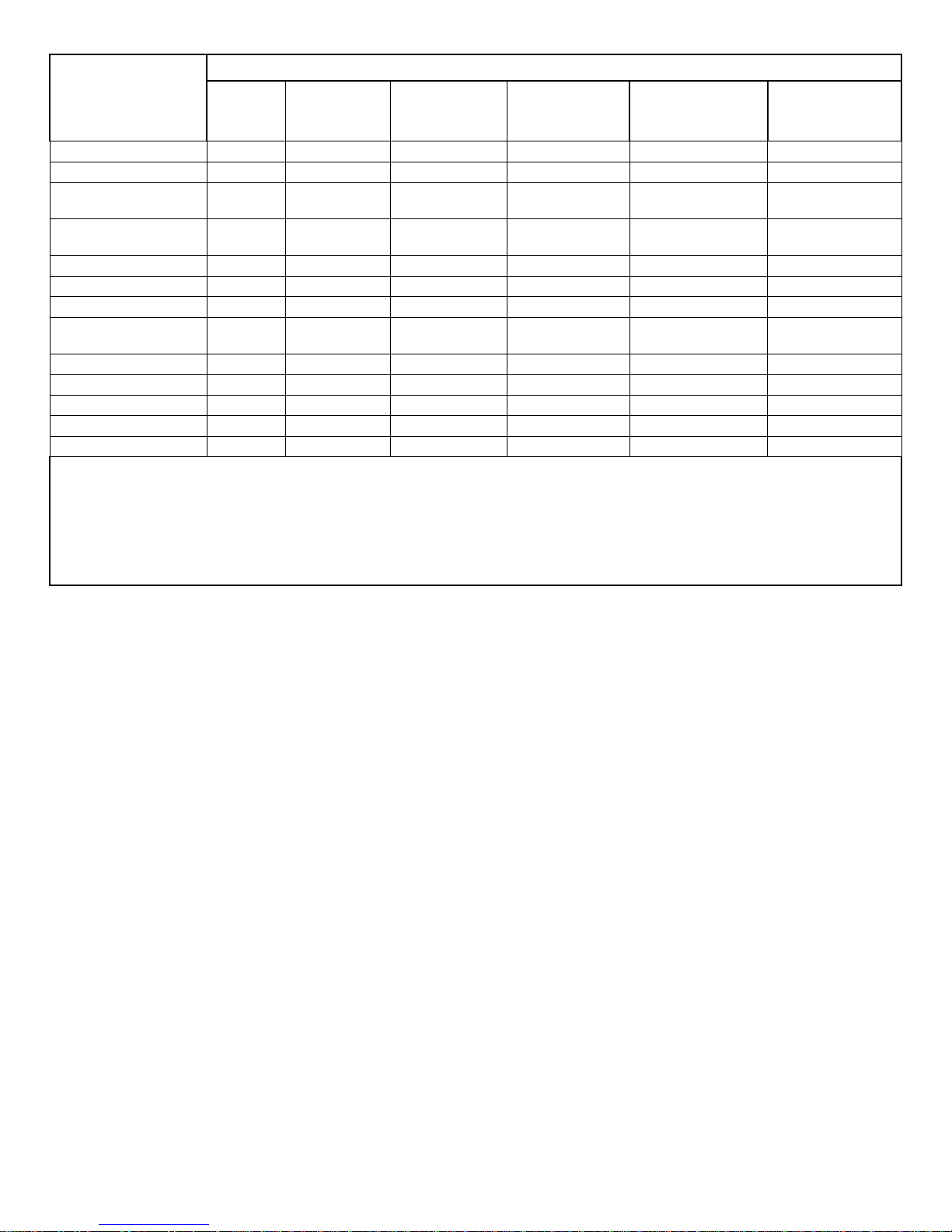
PCB工业监视和测量设备 - 中国RoHS2公布表
PCB Industrial Monitoring and Measuring Equipment - China RoHS 2 Disclosure Table
部件名称
有害物质
铅 (Pb)
汞
(Hg)
镉
(Cd)
六价铬 (Cr(VI))
多溴联苯 (PBB)
多溴二苯醚 (PBDE)
住房
O O O
O O O
PCB板
X O O
O O O
电气连接器
O O O
O O O
压电晶体
X O O
O O O
环氧
O O O
O O O
铁氟龙
O O O
O O O
电子
O O O
O O O
厚膜基板
O O X
O O O
电线
O O O
O O O
电缆
X O O
O O O
塑料
O O O
O O O
焊接
X O O
O O O
铜合金/黄铜
X O O
O O O
本表格依据 SJ/T 11364 的规定编制。
O: 表示该有害物质在该部件所有均质材料中的含量均在 GB/T 26572 规定的限量要求以下。
X: 表示该有害物质至少在该部件的某一均质材料中的含量超出 GB/T 26572 规定的限量要求。
铅是欧洲RoHS指令2011/65/ EU附件三和附件四目前由于允许的豁免。
CHINA RoHS COMPLIANCE
Page 5
Component Name
Hazardous Substances
Lead
(Pb)
Mercury
(Hg)
Cadmium
(Cd)
Chromium VI
Compounds
(Cr(VI))
Polybrominated
Biphenyls
(PBB)
Polybrominated
Diphenyl
Ethers (PBDE)
Housing O O O O O O
PCB Board
X O O O O
O
Electrical
Connectors
O O O O O
O
Piezoelectric
Crystals
X O O O O
O
Epoxy O O O O O O
Teflon O O O O O O
Electronics
O O O O O
O
Thick Film
Substrate
O O X O O
O
Wires O O O O O O
Cables X O O O O O
Plastic O O O O O O
Solder X O O O O O
Copper Alloy/Brass
X O O O O
O
This table is prepared in accordance with the provisions of SJ/T 11364.
O: Indicates that said hazardous substance contained in all of the homogeneous materials for this part is below the limit
requirement of GB/T 26572.
X: Indicates that said hazardous substance contained in at least one of the homogeneous materials for this part is above
the limit requirement of GB/T 26572.
Lead is present due to allowed exemption in Annex III or Annex IV of the European RoHS Directive 2011/65/EU.
DOCUMENT NUMBER: 21354
DOCUMENT REVISION: D
ECN: 46162
Page 6
SENS
ORS AND INSTRUMENTAT
ION FOR MACHINE COND
ITION MONITORING
Model 683A1 ICP® Process Indicator/Controller
Operating Guide with Enclosed Warranty Information
3425 Walden Avenue, Depew, New York 14043-2495
Phone (716) 684-0003
Fax (716) 684-3823
Toll Free Line 1-800-959-4IMI
MANUAL NUMBER: 19163
MANUAL REVISION: C
ECN NUMBER: 18874
Page 7

PAGE 2
SENSORS AND INSTRUME
NTATION FOR MACHINE
CONDITION MONITORING
Table of Contents
Introduction………………………………………………………………………………………. Page 3
General Features, Software Features
Specifications……………………………………………………………………………………. Page 4
Controls and Indicators………………………………………………………………………… Page 5
Glossary of Programming Symbols…………………………………………………………… Page 6
Software Logic Tree…………………………………………………………………………….. Page 7
Programming the 683A1..……………………………………………………………………… Page 8
Wiring and Installation………………………………………………………………………… Page 13
Configuring the 683A1 ……………………………………………………………………….. Page 17
Accessories…………………………………………………………………………………….. Page 18
ESD Sensitivity………………………………………………………………………………… Page 20
Ordering Information………………………………………………………………………….. Page 21
Warranty/Servicing
Warranty, Service & Return Procedure.......................................................................... Page 22
Customer Service.......................................................................................................... Page 23
Page 8

PAGE 3
SENSORS AND INSTRUME
NTATION FOR MACHINE
CONDITION MONITORING
Introduction
The Model 683A1 ICP
®
Process Indicator/Controller is an intelligent 4-digit modular panel meter with software
features for monitoring, measurement, and control applications complete with 0.56” LED in a 1/8 DIN 96x48 case.
The 683A1 operates from a single power supply and will supply 24Vdc/4mA excitation for sensor power. The
indicator/controller comes equipped with two 5 Amp Form A relays with independent setpoints and time delay.
General Features
External transmitters, signal conditioners, or power supplies can be eliminated by direct connection of the
sensor to the indicator/controller.
Optional isolated 16-bit analog output. User or factory scalable to 4 to 20 mA across any desired digital
span from ± one count to the full-scale range of – 1999 to 9999 (12000 counts).
24Vdc/4mA excitation to power sensor.
Standard Internal DIP switch selectable vibration ranges include:
Acceleration (g’s) Velocity (in/sec) Displacement (mils p-p)
5.000 0.500 25.0
10.00 1.000 50.0
20.00 2.000 100.0
Two 5 Amp Form A relays, additionally two 5 Amp Form A or 10 Amp Form C relays are available.
Programmable Time Delay to 9999 seconds.
Internal DIP switch selection for Peak or RMS display.
User specified, factory installed, High and Low pass 2-pole filtering.
Analog output signal connection (RV) for conducting frequency analysis and machinery diagnostics.
Software Features
Three-button front panel programming of:
Scale Factor and Offset
Decimal point setting.
Four-level brightness control of digital display.
Peak and valley view and reset.
Four programmable setpoints.
Adjustable delay-on-make and delay-on-break time for setpoints 1 and 2.
Relay activation can be selected to occur above (HI) or below (LO) each setpoint.
Page 9

PAGE 4
SENSORS AND INSTRUME
NTATION FOR MACHINE
CONDITION MONITORING
Specifications
Input Specs
: ...... 100mV/g
ICP® Sensor Excitation: ...... 24Vdc/4mA, ±1Vdc/±1mA
A/D Converter: ...... 14 bit single slope
Accuracy: ...... ±2.0% of Scale Factor + 2 counts
Frequency Response: 3Hz to 10Khz (Standard)
Acceleration: -3dB at 3Hz ±0.5Hz, -3dB at 10kHz ±0.5kHz
Velocity: -3dB at 3.5Hz ±0.5Hz, -3dB at 10kHz ±0.5kHz
Displacement: -3dB at 3.5Hz ±0.5Hz, 1000Hz max.
Temp. Coeff.: ...... 100 ppm/°C (Typical)
Warm up time: ...... 2 minutes
Conversion Rate: ...... 5 conversions per second (Typical)
Display: ...... 4 digit 0.56" Red LED display, Range –1999 to 9999 counts.
Polarity: ...... Assumed positive. Displays – negative
Decimal Selection: ...... Front panel button selectable, X•X•X•X•
Positive Overrange: ...... Top segments of digital display flash
Negative Overrange: ...... Bottom segment of digital display flash
Relay Output
: ...... Two 5 A Form A (SPST) relays 230VAC/30VDC standard.
Additionally two 5 Amp Form A (SPST) or 10 Amp Form C (SPDT) relays.
Optional Analog Output: ...... Isolated 16 bit user scalable 4-20mA retransmit @ 0 to 500 ohms max
loop resistance.
Power Supply: ...... Auto sensing wide range supply 85-265 VAC / 95-370 VDC @ 2.5W max 3.5W
Operating Temp.: ...... 0 to 60 °C
Storage Temp: ...... –20 °C to 70 °C.
Relative Humidity: ...... <95% (non condensing)
Case Dimensions: ...... 1/8 DIN, Bezel: 96x48 mm (3.78”x1.89”)
Depth behind bezel 117 mm (4.61”)
Plus 11.8 mm (0.47”) for Right-angled connectors, or plus 20 mm (0.79”) for Straight-thru connectors.
Weight: ...... 6.5 oz., 8.5 oz when packed
Page 10

PAGE 5
SENSORS AND INSTRUME
NTATION FOR MACHINE
CONDITION MONITORING
Controls and Indicators
Front Panel Buttons
Program Button
The button is used to move from one program step to the next. When pressed at the same time as the
button, it initiates the calibration mode. When pressed at the same time as the button, it initiates
the setpoint setting mode.
Up Button
When in the operational display, pressing the button alone, allows you to view and reset the Peak and
Valley (Highest and Lowest Readings.)
When in calibration mode or the setpoint setting mode the button is used to increase the value of
the displayed parameter.
Down Button
When in the operational display, pressing the button alone allows you to view, but not change, the
setting of setpoint 1,2,3,& 4.
When in calibration mode or the setpoint setting mode the button is used to decrease the value of
the displayed parameter.
Page 11

PAGE 6
SENSORS AND INSTRUME
NTATION FOR MACHINE
CONDITION MONITORING
Glossary of Programming Symbols
To explain software-programming procedures, logic diagrams are used to visually assist in following the
programming steps. The following symbols are used to represent various functions and associated display
elements of the 683A1:
Symbol Explanation Symbol Explanation
This symbol represents the
OPERATIONAL DISPLAY.
[ScALE]
[9999]
Text or numbers shown between
square brackets in a procedure
indicate the programming code
name of the function or the value
displayed on the meter display.
When a button is shown, press and
release it to go onto the next step in
the direction indicated by the arrow.
When two or more buttons are
shown, each with an arrow, this
indicates there are a number of
programming choices.
When the and buttons are
shown together, the display value
can be increased by pressing and
releasing the button or
decreased by pressing and
releasing the button.
When two buttons are shown side by
side and enclosed by a dotted line,
they must be pressed at the same
time then released to go onto the next
programming step.
When the and buttons are
shown with two displays, either
display can be selected by pressing
and releasing the or
buttons.
If the display is shown with XXXX it
means the value displayed will be the
previously set value. When a number
is shown it indicates the initial factory
default setting or a specific “example
number.”
When there are more than two
display selections they are shown
in brackets below the first display
and are also selectable by pressing
and releasing the or
buttons.
When two displays are shown
together with bursts, this indicates
that the display is toggling (flashing)
between the name of the function and
the value.
A dotted box indicates these
functions are omitted or bypassed
when the related hardware is not
present.
is the PROGRAM button, is the UP button, is the DOWN button.
Page 12

PAGE 7
SENSORS AND INSTRUME
NTATION FOR MACHINE
CONDITION MONITORING
Software Logic Tree
The 683A1 is an intelligent meter with a hierarchical software structure designed for easy programming and
operation, as shown below in the software logic tree. After the meter has been powered up, the four digits light up
for three seconds and then settle to the operational display indicating the input signal.
Page 13

PAGE 8
SENSORS AND INSTRUME
NTATION FOR MACHINE
CONDITION MONITORING
Programming the 683A1
Digital Scaling
The 683A1 meter may be rescaled without applying an external signal by changing the Offset and Scale factor.
Offset is the reading that the meter will display for a 0mV input. The Offset may be set to any value from –1999 to
+9999. The default value of the Offset is 0000.
Scale Factor is the gain of the meter. The displayed reading is directly proportional to the Scale Factor. The
default value of the Scale Factor is 1000 for a 1ips accelerometer, but it may be set to any value between –1999
and +9999.
For an input of 2.000V a calibrated meter will read 1000 with the default Scale Factor of 1000, 2000 with a Scale
Factor of 2000, and 500 with a Scale Factor of 500.
Digital Scaling Procedure
STEP A Enter the Calibration Mode
1) Press the and the buttons at the same time.
Display toggles between [cAL] and [oFF].
2) Press the or button.
Display changes from [oFF] to [on].
3) Press the button. Display toggles between [cAL] and [out].
STEP B Select Between Calibration of Input or Output
Note: If the analog output option is not present, Step B is skipped and the
program goes directly from Step A to Step C.
1) Press the or button to select the display toggling from
[cAL] to [iP].
2) Press the
button. Display toggles between [oFFS] and the
previous offset setting.
STEP C Set the Offset on the Digital Display
1) Using the and buttons, adjust the digital display to the
desired offset. This is the reading the meter will display for a
0mV input.
2) Press the
button. Display toggles between [SCAL] and the
previous scale factor.
STEP D Set the Scale factor on the Digital Display
1) Using the and buttons, adjust the meter display to the
desired Scale Factor. The default value is 1000, for which a
2.000V input will read 1000. If the Scale factor is changed the
display will change proportionally. Therefore if the Scale
Factor is changed to 2000 then for the same 2.000V input the
display will read 2000.
2) Press the button.
The Digital Calibration Procedure Mode is Now Complete.
The menu branches to the DECIMAL POINT AND BRIGHTNESS
SELECTION, (see page 10) and the display flashes [dP] and the previous
decimal point selection.
Page 14

PAGE 9
SENSORS AND INSTRUME
NTATION FOR MACHINE
CONDITION MONITORING
Two Point Analog Output Range Setting and Calibration
STEP A Enter the Calibration Mode
1) Press the and the buttons at the same time.
Display toggles between [cAL] and [oFF].
2) Press the or button. Display changes from [oFF] to [on].
1) Press the button. Display toggles between [cAL] and [out].
Note: If at this point the display skips directly to toggle between [oFFS] and the
previous [oFFS] setting, the software is detecting that the optional analog output
hardware is NOT installed.
STEP B Enter the Analog [oUT] Output Mode
1) Press the
button. Display toggles between [cLo] and internal scale
factor.
STEP C Set or Calibrate the [cLo] Low Analog Output Range
1) Connect a multimeter to pins 16 and 17 on the output module. See
Rear Panel Pinouts on Page 8). Using the and buttons, adjust
the analog output to the desired low value as shown on the
multimeter display. cLo may be adjusted to any value from –
0.3mA to
17mA. (Factory Default is 4mA)
2) Press the button. Display toggles between [cHi] and internal scale
factor.
STEP D Set or Calibrate the [cHi] Analog Output Range
1) Using the and buttons, adjust the analog output to the desired
high value as shown on the multimeter display. cHi may be adjusted
to any value from 17mA to 21mA. (Factory Default is 20mA)
2) Press the button. The display exits the calibration mode and
returns to the operational display.
Note:
Having established the Low and High range of the analog output, the digital
span can now be selected which will set the two digital points between which the
analog output will occur. (See Digital Span selection next page).
Page 15

PAGE 10
SENSORS AND INSTRUME
NTATION FOR MACHINE
CONDITION MONITORING
Decimal Point and Brightness Selection
Digital Span Selection for Analog Range Output
STEP A Enter the Decimal Point and Brightness Mode Through the Sub
Menu [CAL]{oFF]
2) Press the and the buttons at the same time.
Display toggles between [cAL] and [oFF].
3) Press the button. Display shows the previous [dp] selection.
STEP E Set the Decimal Point
1) Using the and buttons, adjust the display to the desired decimal
point setting. (Factory Default is X.XXX)
2) Press the button. Display toggles between [Br] and the previous
[Br] setting.
STEP F Set the Display Brightness
1) Using the and buttons, adjust the display to the desired
brightness setting (4 is the brightest setting).
2) Press the button. Display brightness changes to new setting and
display toggles between [Anhi] and the previous [Anhi] setting.
STEP G Setting the Digital Span Point for Analog High Output
1)
Using the and buttons, adjust the display to the desired digital
value which sets the point at which the selected analog high output
range will occur. (Factory Default is 1000)
2) Press the button. Display toggles between [AnLo] and the
previous [AnLo] setting.
STEP H Setting the Digital Span Point for Analog Low Output
1) Using the and buttons, adjust the display to the desired digital
value which sets the point at which the selected analog low output
range will occur. (Factory Default is 0)
2) Press the button. The display exits the calibration mode and
returns to the operational display.
Note: Any two digital scale points from –1999
to 9999 can be selected. The digital
scale points for analog high and analog low can be reversed for a 20mA to 4mA
output. The span of the digital scale can be as small as two counts however small
spans cause the 16 bit D to A to increment in stair case steps.
Page 16

PAGE 11
SENSORS AND INSTRUME
NTATION FOR MACHINE
CONDITION MONITORING
Setpoint Setting and Relay Configuration Mode
The following programming steps are required to enter the setpoint values and
configure the relay functions in a meter with four relays using four setpoints. Generally
if less than four relays are installed the software auto detects the missing relays and
deletes reference to them from the menu. In some cases setpoints without relays are
operational for display purposes only.
STEP A Enter the Setpoint Mode
1) Press the and buttons at the same time.
Display toggles between [SP1] and the previous [SP1] setting.
STEP B Setpoint1 (SP1)
1) Using the and buttons, adjust the display to the desired SP1 value.
2) Press the button. Display toggles between [doM] and the previous [doM]
setting.
STEP C Set the SP1 Delay-on-Make (doM) Delay Time Setting
1) Using the and buttons, adjust the display to the desired [doM] value
(0 to 9999 seconds). The reading must continuously remain in an alarm
condition until this delay time has elapsed before the relay will make contact
(energize).
2) Press the button. Display toggles between [dob] and the previous [dob]
setting.
STEP D Set the SP1 Delay-on-Break (dob) Delay Time Setting
1) Using the and buttons, adjust the display to the desired [dob] value (0-
9999 seconds). The reading must continuously remain in a non-
alarm condition
until this delay time has elapsed before the relay will break contact (deenergize).
2)
Press the button. Display toggles between [hYST] and the previous [hYST]
setting.
STEP C Set the Hysteresis Setting for Setpoint 1
1) Using the and buttons, adjust the display to the desired hysteresis [hYST]
value.
2)
Press the button. Display toggles between [SP2] and the previous [SP2]
setting.
Note: Steps, F, G, H, and J have functionally the same procedure as steps B, C, D,
and E shown above.
STEP F Set Setpoint 2 (SP2)
STEP G Set the SP2 Delay-on-Make (doM) Delay Time Setting
STEP H Set the SP2 Delay-on-Break (dob) Delay Time Setting
STEP I Set the Hysteresis Setting for Setpoint 2
1) Using the and buttons, adjust the display to the desired hysteresis [hYST]
value.
2) Press the button. Display toggles between [SP3] and the previous [SP3]
setting.
SETPOINT 3
, 4, AND RELAY ACTIVATION MODE CONTINUED NEXT PAGE.
Page 17

PAGE 12
SENSORS AND INSTRUME
NTATION FOR MACHINE
CONDITION MONITORING
STEP J Set Setpoint 3 (SP3)
(No [doM] or [dob])
1)
Using the and buttons, adjust the display to the desired SP3 value.
2) Press the button. Display toggles between [hYST] and the previous [hYST]
setting.
STEP K Set the Hysteresis Setting for Setpoint 3
1) Using the and
buttons, adjust the display to the desired hysteresis [hYST]
value.
2) Press the button. Display toggles between [SP4] and the previous [SP4]
setting.
STEP L Set Setpoint 4 (SP4) (No [doM] or [dob])
1) Using the and buttons, adjust the display to the desired SP4 value.
2) Press the button. Display toggles between [hYST] and 0.
STEP M Set the Hysteresis Setting for Setpoint 4
1) Using the and buttons, adjust the display to the
desired hysteresis [hYST]
value.
2) Press the button. Display toggles between [rLYS] and the previous relay
setting.
STEP N Set Relay Activation mode [rLYS]
(h) High the relay energizes when the setpoint is exceeded. (L) Low the relay
energizes below the setpoint. The setpoint is indicated from left to right SP1, SP2, SP3,
SP4.
1) Using the and buttons, adjust the reading on the display to the desired
relay settings: [LLLL], [LhLh], [hLhL], [hhhh].
If only 2 relays installed [Lh--], [hL--], [hh--], [LL--].
2) Press the button. The meter exits the setpoint mode and returns to the
operational display.
The Setpoint Relay programming mode is now complete.
Page 18

PAGE 13
SENSORS AND INSTRUME
NTATION FOR MACHINE
CONDITION MONITORING
Wiring and Installation
Pinout Diagram
The Rear View Meter diagram shows
the meter with the relay configuration:
dual 10 Amp Form C and dual 5 Amp
Form A relays. An analog output
module is also shown as installed.
The 683A1 uses plug-in type screw
terminal connectors for all input and
output connections. The power supply
connections (pins 14 and 15) have a
unique plug and socket outline to
prevent cross connection. The main
board and input signal conditioner use
right –angled connectors as standard.
The output module uses straight–thru
connectors as standard.
Connectors
WARNING
AC and DC input signals and power supply voltages can be hazardous. DO NOT
connect live wires to screw terminal plugs, and DO NOT insert, remove, or handle screw
terminal plugs with live wires connected.
Page 19

PAGE 14
SENSORS AND INSTRUME
NTATION FOR MACHINE
CONDITION MONITORING
Typical Wiring Diagram (CE Power Supply Option)
To Maintain Conformance I/O Shields must be connected to Pin 3 on the Panel Meter
and all Supplied Accessories must be wired as shown (Power Supply Option 2).
1 2 3 4 5 8 9 10 11
14 15
ICP SENSOR/
SIMULATOR
RV OUTPUT
DMM
+
-
+
-
SHIELD
N/C N/C N/C N/C
3EB1LB
+
-
CORCOM
EMI FILTER
+
-
AC
LINE
AC
NEUTRAL
GND
METALLIC
ENCLOSURE
Page 20

PAGE 15
SENSORS AND INSTRUME
NTATION FOR MACHINE
CONDITION MONITORING
Pin Descriptions
Input Signal - Pins 1 to 6
Pin 1 +ICP® Sensor Excitation/Signal
Pin 2 -ICP® Sensor Excitation
Pin 3 ICP® Sensor Shield (if applicable)
Pin 4 + RV Output (Analog Sensor Signal)
Pin 5
- RV Output (Analog Sensor Signal)
Pin 6 No Connection
Relay Output - Pins 8 to 12
Pin 8 SP1 NO. (Normally Open 5 Amp Form A.)
Pin 9 SP1 NO.
Pin 10 SP2 NO. (Normally Open 5 Amp Form A.)
Pin 11 SP2 NO.
Pin 12 No Connection
AC/DC Power Unit - Pins 14 and 15
Pin 14 AC/DC Neutral. Neutral power supply line.
Pin 15 AC/DC Line. Live power supply line.
OPTIONAL TOP BOARD PINS
Analog Output - Pins 16 and 17
Pins 16 and 17 are the analog output pins on the optional output module.
Pin 16
Positive (+) analog output.
Pin 17 Negative (-) analog output.
Rear Panel Function – Pins 18 to 21
Pin 18 DIM. By connecting the display dim (DIM) pin to the COMMON pin, the display brightness setting is
halved.
Pin 19 COMMON. To activate the LOCK or DIM functions from the rear of the meter, the respective pins have to
be connected to the COMMON pin. This pin is connected to the internal power supply ground.
Pin 20 HOLD. By connecting the HOLD pin to the COMMON pin, the display reading is frozen, however, A/D
conversions continue. When the HOLD pin is disconnected from the COMMON pin, the correct reading is
displayed.
Pin 21 LOCK. By connecting the LOCK pin to the COMMON pin, the meter’s parameters can be viewed but not
changed.
Top Board Secondary Relay Output – Pins 22 to 29
Quad 5A Form A Relays or Dual 10Amp Form C Relays.
Pin 22 SP1 (Quad 5A SPST Relay Option)
Pin 23 SP1 (Quad 5A SPST Relay Option), SP3 COMM (10A SPDT Additional Relay Option)
Pin 24
SP2 (Quad 5A SPST Relay Option), SP3 NC (10A SPDT Additional Relay Option)
Pin 25 SP2 (Quad 5A SPST Relay Option), SP3 NO (10A SPDT Additional Relay Option)
Pin 26 SP3 (Quad 5A SPST Relay Option)
Pin 27 SP3 (Quad 5A SPST Relay Option), SP4 COMM (10A SPDT Additional Relay Option)
Pin 28 SP4 (Quad 5A SPST Relay Option), SP4 NC (10A SPDT Additional Relay Option)
Pin 29 SP4 (Quad 5A SPST Relay Option), SP4 NO (10A SPDT Additional Relay Option)
Page 21

PAGE 16
SENSORS AND INSTRUME
NTATION FOR MACHINE
CONDITION MONITORING
Case Dimensions and Panel Cutout
Page 22

PAGE 17
SENSORS AND INSTRUME
NTATION FOR MACHINE
CONDITION MONITORING
Configuring the 683A1
ICP® Interface PC Board Diagram
The ICP® Interface Board Diagram
shows the location of the internal
DIP switch. This DIP switch is
used to configure the indicator for
various sensor and vibration
ranges. The PC Board is
accessible through the back of the
indicator by removing the Screw
Terminal Plugs and back panel.
The back panel is released by
disengaging the tabs on the TOP
and BOTTOM of the meter with a
screwdriver. Once removed, the
ICP® Interface Board can be slid
out for configuration.
Internal DIP Switch Setting
The Internal DIP Switch of the Model 683A1 must be configured for the Full Scale Output of the ICP® Sensor
connected to it. This is accomplished by removing the back cover and sliding the ICP® Interface PC Board out of
the Panel Meter/Controller. Once removed, the DIP switch should be configured per one of the conditions in the
following table.
Range Setting S1 S2 S3 S4 S5 S6 S7 S8
5g RMS
ON
OFF
OFFONOFF
OFF
OFF
ON
5g Peak
ON
OFF
OFF
OFFONOFF
OFF
ON
10g RMS
ON
OFF
OFFONOFF
OFFONOFF
10g Peak
ON
OFF
OFF
OFFONOFFONOFF
20g RMS
ON
OFF
OFFONOFFONOFF
OFF
20g Peak
ON
OFF
OFF
OFFONON
OFF
OFF
0.5 in/sec RMS
OFFONOFFONOFF
OFF
OFF
ON
0.5 in/sec Peak
OFFONOFF
OFFONOFF
OFF
ON
1.0 in/sec RMS
OFFONOFFONOFF
OFFONOFF
1.0 in/sec Peak
OFFONOFF
OFFONOFFONOFF
2.0 in/sec RMS
OFFONOFFONOFFONOFF
OFF
2.0 in/sec Peak
OFFONOFF
OFFONON
OFF
OFF
25 mils p-p
OFF
OFFONOFF
OFF
OFF
OFF
ON
50 mils p-p
OFF
OFFONOFF
OFF
OFFONOFF
100 mils p-p
OFF
OFFONOFF
OFFONOFF
OFF
Note: Factory Default Setting is 1.0in/sec Peak
5
4
3
2
1
ONOFF
Selector
Switch
S1
S2
S3
S4
S5
S6
S7
S8
Page 23

PAGE 18
SENSORS AND INSTRUME
NTATION FOR MACHINE
CONDITION MONITORING
Accessories
NEMA 4X Lens Cover
The lens cover is designed to be dust and water
proof to NEMA-4X standards. The lens cover
consists of a base and cover with a cam hinge and
key-lock locking device.
An O-ring, or neoprene gasket forms a seal between
the base and the panel. The cam hinge prevents the
cover from closing when opened until pushed closed.
The cover has a tapered recess that, when closed,
forms a capillary seal with a tapered ridge on the
base. Turning the key-lock tightens the cover to the
base, insuring seal integrity. A safety catch keeps the
cover closed even when the key is turned to the
open position and removed. The keyhole can also be
used to attach a safety seal clop, preventing
unauthorized opening.
Page 24

PAGE 19
SENSORS AND INSTRUME
NTATION FOR MACHINE
CONDITION MONITORING
Metal Surround Case
The meter’s plastic case is made from a fire retardant polycarbonate. A metal surround case can be ordered to
enhance the meter’s fire retardant capabilities and also provide shielding against electromagnetic interference
(EMI). The metal case slides over the polycarbonate case and is held firmly in place by spring-type non-return
clips. Once the metal case has been fitted to the polycarbonate case it cannot be removed.
With the metal case in place, the meter’s plastic ratchet-type mounting clips can no longer be used. A pair of
screw-type mounting clips are inserted into holes on the side of the metal case and used to mount the meter in
the panel. A ground tab on the metal case provides a ground connection between the meter’s main board and the
metal case.
**Metal Surround Case must be factory installed.
Page 25

PAGE 20
SENSORS AND INSTRUME
NTATION FOR MACHINE
CONDITION MONITORING
Warning 1 – ESD sensitivity
The power supply/signal conditioner should not be opened by anyone other than qualified service
personnel. This product is intended for use by qualified personnel who recognize shock hazards and are familiar
with the safety precautions required to avoid injury.
Warning 2 – ESD sensitivity
This equipment is designed with user safety in mind; however, the protection provided by the equipment may be
impaired if the equipment is used in a manner not specified by PCB Piezotronics, Inc.
Caution 1 – ESD sensitivity
Cables can kill your equipment. High voltage electrostatic discharge (ESD) can damage electrical devices.
Similar to a capacitor, a cable can hold a charge caused by triboelectric transfer, such as that which occurs in the
following:
Laying on and moving across a rug,
Any movement through air,
The action of rolling out a cable, and/or
Contact with a non-grounded person.
The PCB solution for product safety:
Connect the cables only with the AC power off.
Temporarily “short” the end of the cable before attaching it to any signal input or output.
Caution 2 – ESD sensitivity
ESD considerations should be made prior to performing any internal adjustments on the equipment. Any
piece of electronic equipment is vulnerable to ESD when opened for adjustments. Internal adjustments should
therefore be done ONLY at an ESD-safe work area. Many products have ESD protection, but the level of
protection may be exceeded by extremely high voltage.
Page 26

PAGE 21
SENSORS AND INSTRUME
NTATION FOR MACHINE
CONDITION MONITORING
Ordering Information
IMI Part Number: 683A 1 1 0 2 0 3
Basic Model Number
683A
Sensor Input
1 100mV/g ICP® Sensor
Power Supply
0 85-265Vac/95-370Vdc
1 18-48Vac/10-72Vdc
2 85-265Vac/95-370Vdc CE Certified.
Analog Output*
0 None
1 Isolated 16 bit user scalable 4-20mA retransmit.
Additional Relay Output*
0 None
1 Dual 10 Amp Form C Relays (SPDT)
2 Dual 5 Amp Form A Relays (SPST)
Frequency Response*
0 3Hz to 10kHz (Standard)
1 3Hz to 1kHz
2 10Hz to 10kHz
3 10Hz to 1kHz
Accessories*
0 None
1 96x48mm Clear Lockable Front Cover – NEMA 4X, Splash Proof.
2 Metal Surround Case – Includes screw mounting clips.
3 Clear Lockable Front Cover and Metal Surround Case.
Ordering Example: 683A100001
This is a standard ICP® Indicator/Controller with the following:
Power Supply: 85-265Vac/95-370Vdc
Analog Output: None
Additional Relay Output: None
Frequency Response: Standard (3Hz to 10kHz)
Accessories: 96x48mm Clear Lockable Front Cover – NEMA 4X, Splash Proof.
*Additional Options Available – Please Inquire
Page 27

PAGE 22
SENSORS AND INSTRUME
NTATION FOR MACHINE
CONDITION MONITORING
Warranty
IMI instrumentation is warranted against defective material and workmanship for 1 year unless otherwise
expressly specified. Damage to instruments caused by incorrect power or misapplication, is not covered by
warranty. If there are any questions regarding power, intended application, or general usage, please consult with
your local sales contact or distributor. Batteries and other expendable hardware items are not covered by
warranty.
Service
Because of the sophisticated nature of IMI instrumentation, field repair is typically NOT recommended and may
void any warranty. If factory service is required, return the instrumentation according to the “Return Procedure”
stated below. A repair and/or replacement quotation will be provided prior to servicing at no charge. Before
returning the unit, please consult a factory IMI applications engineer concerning the situation as certain problems
can often be corrected with simple on-site procedures.
Return procedure
To expedite returned instrumentation, contact a factory IMI applications engineer for a RETURN MATERIAL
AUTHORIZATION (RMA) NUMBER. Please have information available such as model and serial number. Also,
to insure efficient service, provide a written description of the symptoms and problems with the equipment to a
local sales representative or distributor, or contact IMI if none are located in your area.
Customers outside the U.S. should consult their local IMI distributor for information on returning equipment. For
exceptions, please contact the International Sales department at IMI to request shipping instructions and an RMA.
For assistance, please call (716) 684-0003, or fax us at (716) 684-3823. You may also receive assistance via email at imi@pcb.com or visit our web site at www.pcb.com.
Page 28

PAGE 23
SENSORS AND INSTRUME
NTATION FOR MACHINE
CONDITION MONITORING
Customer Service
IMI, a division of PCB Piezotronics, guarantees Total Customer Satisfaction. If, at any time, for any reason, you
are not completely satisfied with any IMI product, IMI will repair, replace, or exchange it at no charge. You may
also choose, within the warranty period, to have your purchase price refunded.
IMI offers to all customers, at no charge, 24-hour phone support. This service makes product or application
support available to our customers, day or night, seven days a week. When unforeseen problems or emergency
situations arise, call the IMI Hot Line at (716) 684-0003, and an application specialist will assist you.
3425 Walden Avenue, Depew, NY 14043-2495
Phone: (716) 684-0003 USA Fax: (716) 684-3823 INTL Fax: (716) 684-4703
ICP® is a registered trademark of PCB Group, Incorporated,
which uniquely identifies PCB sensors that incorporate built-in microelectronics.
Page 29

Model Number
683A100000
INDICATOR / ALARM (FOR ICP® SENSORS)
Revision: A
ECN #: 46956
[3]
Performanc
e
ENGLISH S
I
Sensor Input Type(s) ICP® ICP®
Input Signal 100 mV/g 100 mV/(m/s²)
Frequency Response(± 3 dB) 3 to 10k Hz 3 to 10k Hz
Channels 1 1
Accuracy ±2 % FS ±2 % FS
Measurement Range(Acceleration) 5 g 5 g
[1][2]
Measurement Range(Acceleration) 10 g 10 g
[1][2]
Measurement Range(Acceleration) 20 g 20 g
[1][2]
Measurement Range(Velocity) 0.50 in/sec 0.50 in/sec
[1][2]
Measurement Range(Velocity) 1.00 in/sec 1.00 in/sec
[1][2]
Measurement Range(Velocity) 2.00 in/sec 2.00 in/sec
[1][2]
Measurement Range(Displacement) 25.0 mil pk - pk 25.0 mil pk - pk
[1][2]
Measurement Range(Displacement) 50.0 mil pk - pk 50.0 mil pk - pk
[1][2]
Measurement Range(Displacement) 100.0 mil pk - pk 100.0 mil pk - pk
[1][2]
Relay Type(Alert) 5A Form A 230 VAC/30 VDC 5A Form A 230 VAC/30 VDC
Relay Type(Alarm) 5A Form A 230 VAC/30 VDC 5A Form A 230 VAC/30 VDC
Delay 0 to 9999 sec 0 to 9999 sec
Environmenta
l
Temperature Coefficient of Sensitivity 56 ppm/°F 100 ppm/°C
Warm Up <2 minutes <2 minutes
Temperature Range(Operating) 32 to 140 °F 0 to 60 °C
Temperature Range(Storage) -4 to 158 °F -20 to 70 °C
Humidity Range(Non-Condensing) <95 % <95 %
Electrical
Power Required(Auto Sensing) 85-265 VAC/95-370 VDC 85-265 VAC/95-370 VDC
Current Consumption(Typical) 2.5 W 2 .5 W
Current Consumption(Max) 3.5 W 3.5 W
Excitation Voltage(± 1 VDC) 24 VDC 24 VDC
Constant Current Excitation(± 1 mA) 4 mA 4 mA
Physica
l
Size (Depth x Width x Height) 4.61 in x 3.45 in x 1.61 in 117 mm x 87.4 mm x 40.8 mm
Housing Material Polycarbonate Polycarbonate
Weight 8.5 oz 241 gm
Din Rail Mount 1/8 in 3 mm
Electrical Connector Removable Screw Terminals Removable Screw Terminals
BEZEL 3.78 x 1.89 in 96 x 48 mm
Depth Behind BEZEL 4.61 in 117 mm
Depth Behind BEZEL(Rt. Angle Conn.) 5.08 in 129 mm
Depth Behind BEZEL(Straight Conn.) 5.40 in 137 mm
Accessories None None
All specifications are at room temperature unless otherwise specified.
In the interest of constant product improvement, we reserve the right to change specifications without notice.
ICP
®
is a registered trademark of PCB Group, Inc.
OPTIONAL VERSIONS
Optional versions have identical specifications and accessories as listed for the standard model
except where noted below. More than one option may be used.
NOTES:
[1]
Factory set, 0.5 in/sec rms
.
[2] Internal Dip switch selectable
[3] See PCB Declaration of Conformance PS050 for details.
Entered: LK Engineer: BAM Sales: WD
C
Approved: BAM Spec Number:
Date: 8/8/2017 Date: 8/8/2017 Date: 8/8/2017 Date: 8/8/2017
19278
3425 Walden Avenue, Depew, NY 14043
Phone: 800-959-4464
Fax: 716-684-3823
E-Mail: imi@pcb.com
Page 30

 Loading...