

IMI NORGREN VS18G, VS26S, VS26G, VS18S Operation & Service Manual

Operation & Service
Manual
Valve island VS18/VS26
with EtherNet/IP Interface

2
Operation & Service Manual
Valve islands VS18/VS26 EtherNet/IP
09/2018
Construction & Design is subject to change © 2018 Norgren GmbH
Change history:
The Change history reflects all changes of the Operation & Service Manual, which were done after
the initial release.
Index
Chapters
Change description
Date
Name
001
All
Set up initial version
07/03/2017
002
All
Some corrections were made
21/03/2017
003 2 Chapter „Important hints“ added.
20/07/2017
004
All
Changes in IP Address set up, I/O data,
solenoid object, …
31/07/2017
005
All
ISEM description added, valve island
extension added, minor comments
07/11/2017
006
2, 4.4, 10.1,
10.11, 12.2, 12.3
Power-up description updated, ATEX
Note added, Mounting kit added, FW
version and serial number added, New 2
station SPI board added, soft start valve
rules added, technical data corrected
07/09/2018
This Operation & Service Manual makes no claims of being complete as it does not cover all
variants of the VS18/VS26 valve islands series at the moment.
Therefore this document is subject to extensions or changes.

3
Operation & Service Manual
Valve islands VS18/VS26 EtherNet/IP
09/2018
Construction & Design is subject to change © 2018 Norgren GmbH
Content
1. About this documentation .......................................................................................................................... 5
2. Important hints ........................................................................................................................................... 6
2.1 Grounding and equipotential bonding ................................................................................................ 6
2.2 Intermediate supply/exhaust module (ISEM) ..................................................................................... 6
2.3 ATEX Note .......................................................................................................................................... 6
2.4 Power-up and initialization phase of the VS18/VS26 valve island ..................................................... 7
2.4.1 Firmware release V1.001 and lower ........................................................................................... 7
2.4.2 Firmware release V1.002 and higher ......................................................................................... 7
2.5 Mounting kit 2-in-1 .............................................................................................................................. 8
2.5.1 DIN-rail assembly without mounting bracket .............................................................................. 8
2.5.2 Mounting panel assembly without mounting bracket.................................................................. 9
2.5.3 DIN-rail assembly using the mounting bracket ........................................................................... 9
2.5.4 Mounting panel assembly using the mounting bracket ............................................................ 10
3. Electrical Connections of the VS18/VS26 valve islands ......................................................................... 11
3.1 EtherNet/IP Bus connectors Port 1 & Port 2 .................................................................................... 12
3.2 POWER supply connector ................................................................................................................ 12
4. Commisioning .......................................................................................................................................... 13
4.1 EDS File Installation ......................................................................................................................... 13
4.2 Hardware configuration: Select valve island .................................................................................... 14
4.3 Set up IP Address ............................................................................................................................. 17
4.3.1 Using a DHCP Server ............................................................................................................... 17
4.3.2 Static IP Address assignment using TCP/IP Interface Object .................................................. 17
4.4 Firmware version and serial number ................................................................................................ 19
5. I/O connection via Assembly Object ....................................................................................................... 21
5.1 Bit allocation valve stations .............................................................................................................. 21
5.2 Input data (Assembly Object Instance: 101d) .................................................................................. 22
5.3 Output data (Assembly Object Instance: 100d)................................................................................ 24
6. Solenoid Object ....................................................................................................................................... 25
7. Diagnostics and LEDs ............................................................................................................................. 26
7.1 Status LEDs ...................................................................................................................................... 26
7.1.1 Status LEDs description ........................................................................................................... 26
7.1.2 Link states for Port P1 and Port P2 .......................................................................................... 26
7.1.3 Network Status LED (NS) ........................................................................................................ 26
7.1.4 Module Status LED (MS) ......................................................................................................... 26
7.1.5 Electronics Power Supply Status, LED (VB) ............................................................................ 27
7.1.6 Valve Power Supply Status, LED (VA) ..................................................................................... 27
7.2 Valve slice Status LEDs ................................................................................................................... 27
8. Output behavior in fault condition (Idle mode/Fault mode) ..................................................................... 28
9. Properties EtherNet/IP Interface ............................................................................................................. 29
10. Valve island extension .......................................................................................................................... 30
10.1 Overview – possible combinations ................................................................................................... 30
10.2 Valve island with 4 stations .............................................................................................................. 31
10.3 Valve island with 6 stations .............................................................................................................. 31
10.4 Valve island with 8 stations .............................................................................................................. 32
10.5 Valve island with 10 stations ............................................................................................................ 32
10.6 Valve island with 12 stations ............................................................................................................ 33
10.7 Valve island with 14 stations ............................................................................................................ 33
10.8 Valve island with 16 stations ............................................................................................................ 34
10.9 Valve island with 18 stations ............................................................................................................ 34
10.10 Valve island with 20 stations ............................................................................................................ 34
10.11 Usage of Soft-start valves ................................................................................................................ 35
11. Electrical data ....................................................................................................................................... 36
12. Technical data ...................................................................................................................................... 37
12.1 Technical data VS18 and VS26........................................................................................................ 37
12.2 Technical data VS18 ........................................................................................................................ 38
12.3 Technical data VS26 ........................................................................................................................ 38

4
Operation & Service Manual
Valve islands VS18/VS26 EtherNet/IP
09/2018
Construction & Design is subject to change © 2018 Norgren GmbH
Contact information
Norgren GmbH
Site Fellbach
Stuttgarter Straße 120
70736 Fellbach
Tel: +49 711 5209-0

5
Operation & Service Manual
Valve islands VS18/VS26 EtherNet/IP
09/2018
Construction & Design is subject to change © 2018 Norgren GmbH
1. About this documentation
This Operation & Service Manual contains the information to set up and operate the VS18/VS26
valve islands with EtherNet/IP interface and to detect and resolve problems.
Note:
In addition to the specific information for the EtherNet/IP variants, all data sheets for the
VS18/VS26 valve island series are applicable and remain valid. The difference between the both
variants consists of the sizes of valves and the resulting maximum flow rate. All electrical
connections and parameterization are the same for both variants.
Refer also to the datasheets on the following weblinks:
http://cdn.norgren.com/pdf/en_5_1_250_VS18.pdf
http://cdn.norgren.com/pdf/en_5_1_350_VS26.pdf
Refer also to the installation video on the following web link:
https://player.vimeo.com/video/256919223
6
Operation & Service Manual
Valve islands VS18/VS26 EtherNet/IP
09/2018
Construction & Design is subject to change © 2018 Norgren GmbH
2. Important hints
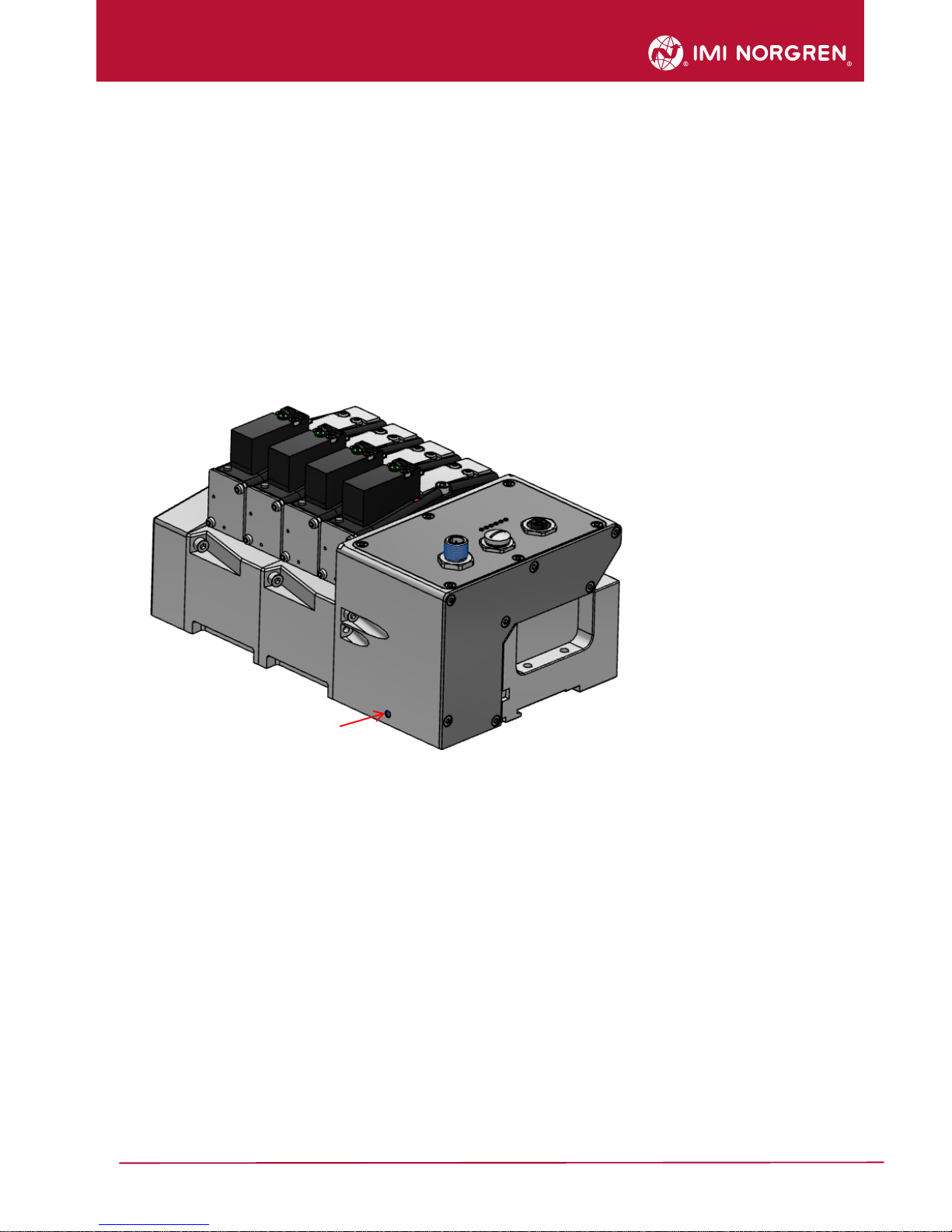
2.1 Grounding and equipotential bonding
Proper grounding and equipotential bonding are very important to protect against electromagnetic
interferences in Ethernet networks. In order to reduce potential impact, grounding of the Ethernet
cable screen should be done at both ends of every cable (i.e. at each device). Equipotential
bonding ensures that the ground potential is identical throughout the entire Ethernet network and is
essential to avoid equipotential bonding currents, which could otherwise flow through the Ethernet
cable screen.
Ground connection needs to be established using the M4 thread on the rear of the connection
module. Its location shows the red arrow on the following picture.
2.2 Intermediate supply/exhaust module (ISEM)
In cases where the channel diagnostics is activated on the valve island, the channel diagnostics
setting should be disabled at the position of each ISEM. This needs to be done in order to avoid
any misleading failure indication due to missing electronic components in the ISEM.
2.3 ATEX Note
Please refer to the corresponding ATEX installation instructions and the maximum permissible
operating conditions for valve islands in an ATEX zone.
The maximum allowed power consumption is 20W. This corresponds to 16 simultaneously
energized pilot valves. If a configuration consists of more than 16 pilot valves the user must
undertake external actions (e.g. power-limited power supplies) to make sure that the power
consumption of 20W is not exceeded.
For further details, please refer to the corresponding ATEX installation instructions or contact your
Technical Support.

7
Operation & Service Manual
Valve islands VS18/VS26 EtherNet/IP
09/2018
Construction & Design is subject to change © 2018 Norgren GmbH
2.4 Power-up and initialization phase of the VS18/VS26 valve island
It is possible to read the actual installed firmware release using the Logix-Designer from AllenBradley. Please refer to chapter 4.4 for more details.
2.4.1 Firmware release V1.001 and lower
The valve island initializes automatically after power-up. During initialization the number of
available valve stations is also evaluated, which requires that at this point also the power supply for
the valves (VA) is already available during initialization start. Otherwise not all valve stations might
be detected and initialization of the valve island fails. This failure case is indicated by the following
permanent Status LED states:
P1 – off
P2 – off
NS – off
MS – red
VB – green
VA – green
2.4.2 Firmware release V1.002 and higher
The requirement as described in chapter 2.4.1 is not applicable for the firmware release V1.002
and higher.
The initialization of the valve island is performed during the testing in production before delivery.
Note:
In case any changes are made on the hardware of the valve islands (i.e. adding or removing valve
stations), the power supply must be completely disconnected by unplugging the power supply
connector.
After the hardware change is completed, the new configuration must be initialized.
During initialization the number of available valve stations is evaluated, it is therefore required to
have both the power supply for electronics (VB) and power supply for the valves (VA) available.
Furthermore it is required to adjust the valve island size in the PLC / Hardware configuration for
proper functioning and diagnosis.
8
Operation & Service Manual
Valve islands VS18/VS26 EtherNet/IP
09/2018
Construction & Design is subject to change © 2018 Norgren GmbH
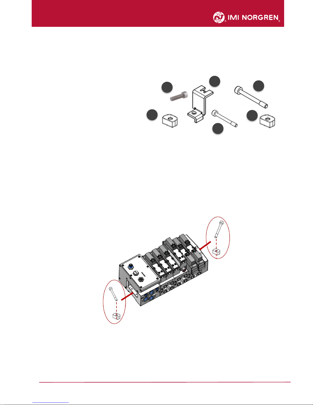
2.5 Mounting kit 2-in-1
Every valve island delivery contains the mounting kit 2-in-1 (part number VS2672971-KG00) as
shown in the below figure. This mounting kit can be used to mount the valve island either to the
DIN rail or directly to the mounting panel.
1. Mounting nut DIN rail
2. Cylinder screw M4 x 8
3. Mounting bracket
4. Cylinder screw M4 x 25
5. Cylinder screw M4 x 36
2.5.1 DIN-rail assembly without mounting bracket
Insert screw M4 x 25 (4) into the left end plate (bus node) and position below the mounting
nut (1)
Insert screw M4 x 36 (5) into the right end plate and position below the mounting nut (1)
Place the valve island on the DIN-rail
Orientate straight flange of the mounting nuts towards the DIN rail
Push the valve island on the DIN-rail and tighten screws with the torque of 1.0 – 1.1 Nm
Check the fit of the valve island
DIN-rail assembly without mounting bracket
1 4 3 5 2
1
9
Operation & Service Manual
Valve islands VS18/VS26 EtherNet/IP
09/2018
Construction & Design is subject to change © 2018 Norgren GmbH
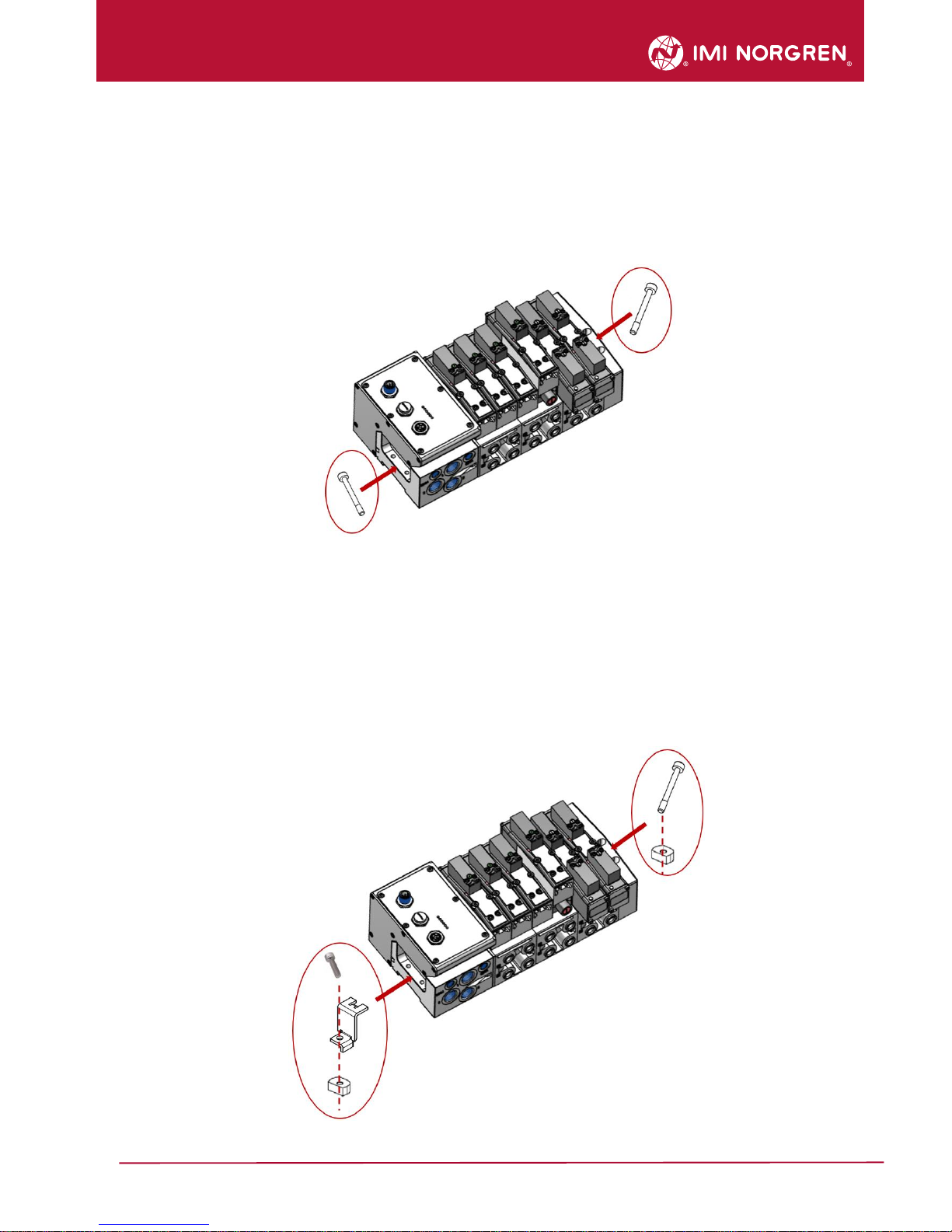
2.5.2 Mounting panel assembly without mounting bracket
Insert screw M4 x 25 (4) into the left end plate (bus node)
Insert screw M4 x 36 (5) into the right end plate
Place the valve island on the panel/ wall
Tighten screws with the torque of 1.0 – 1.1 Nm
Check the fit of the valve island
Mounting panel assembly without mounting bracket
2.5.3 DIN-rail assembly using the mounting bracket
Hook the mounting bracket (3) into the left end plate (bus node)
Insert screw M4 x 8 (2) into the mounting bracket (3) and position below the mounting nut (1)
Insert screw M4 x 36 (5) on the right end plate and position below the mounting nut (1)
Place the valve island on the DIN-rail
Orientate straight flange of the mounting nuts (1) towards the DIN rail
Push the valve island on the DIN-rail and tighten screws with the torque of 1.0 – 1.1 Nm
Check the fit of the valve island
DIN-rail assembly using the mounting bracket
10
Operation & Service Manual
Valve islands VS18/VS26 EtherNet/IP
09/2018
Construction & Design is subject to change © 2018 Norgren GmbH
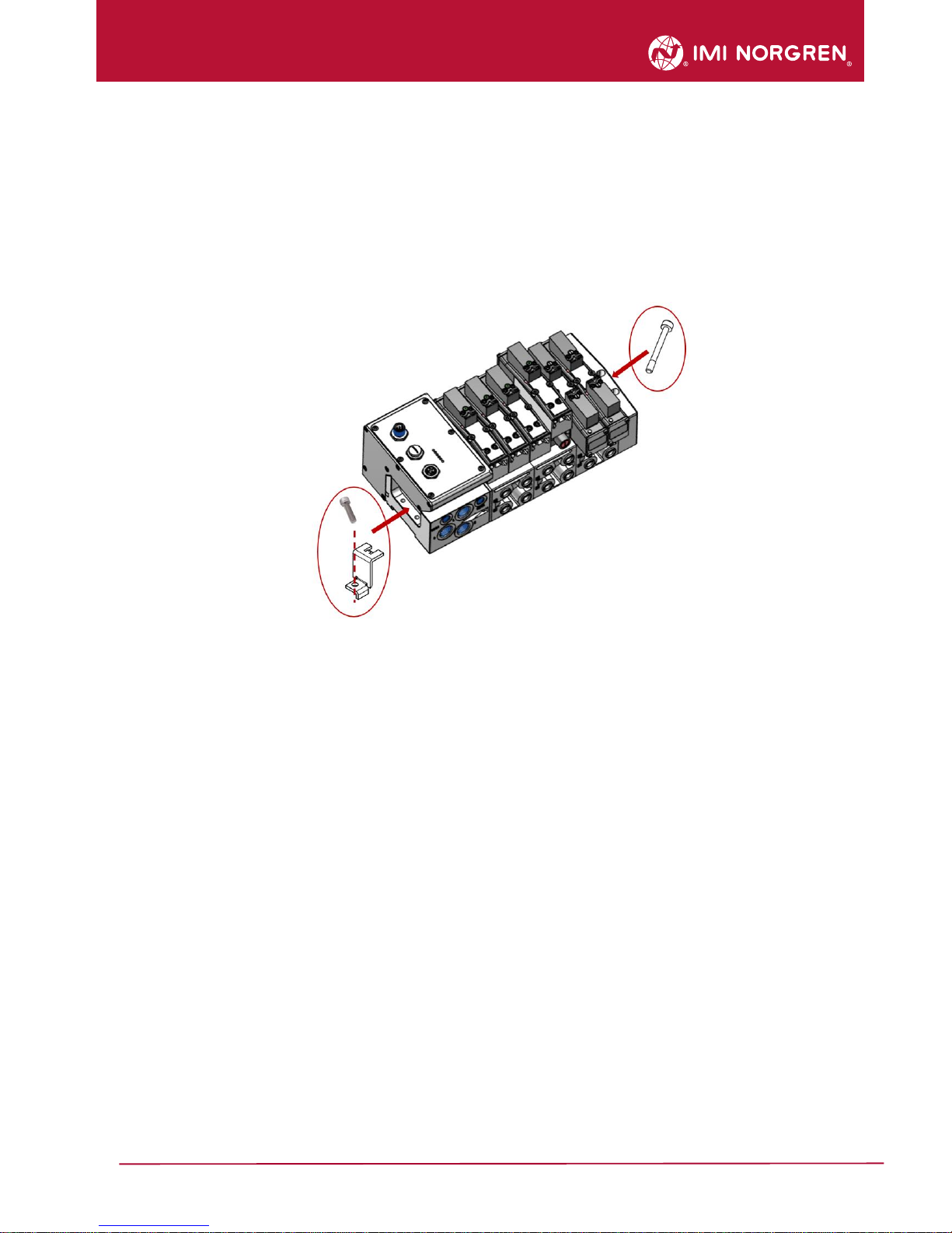
2.5.4 Mounting panel assembly using the mounting bracket
Hook the mounting bracket (3) into the left end plate (bus node)
Insert screw M4 x 8 (2) into the mounting bracket (3)
Insert screw M4 x 36 (5) on the right end plate
Place the valve island on the mounting panel/ wall
Tighten screws with the torque of 1.0 – 1.1 Nm
Check the fit of the valve island
Mounting panel assembly using the mounting bracket
11
Operation & Service Manual
Valve islands VS18/VS26 EtherNet/IP
09/2018
Construction & Design is subject to change © 2018 Norgren GmbH
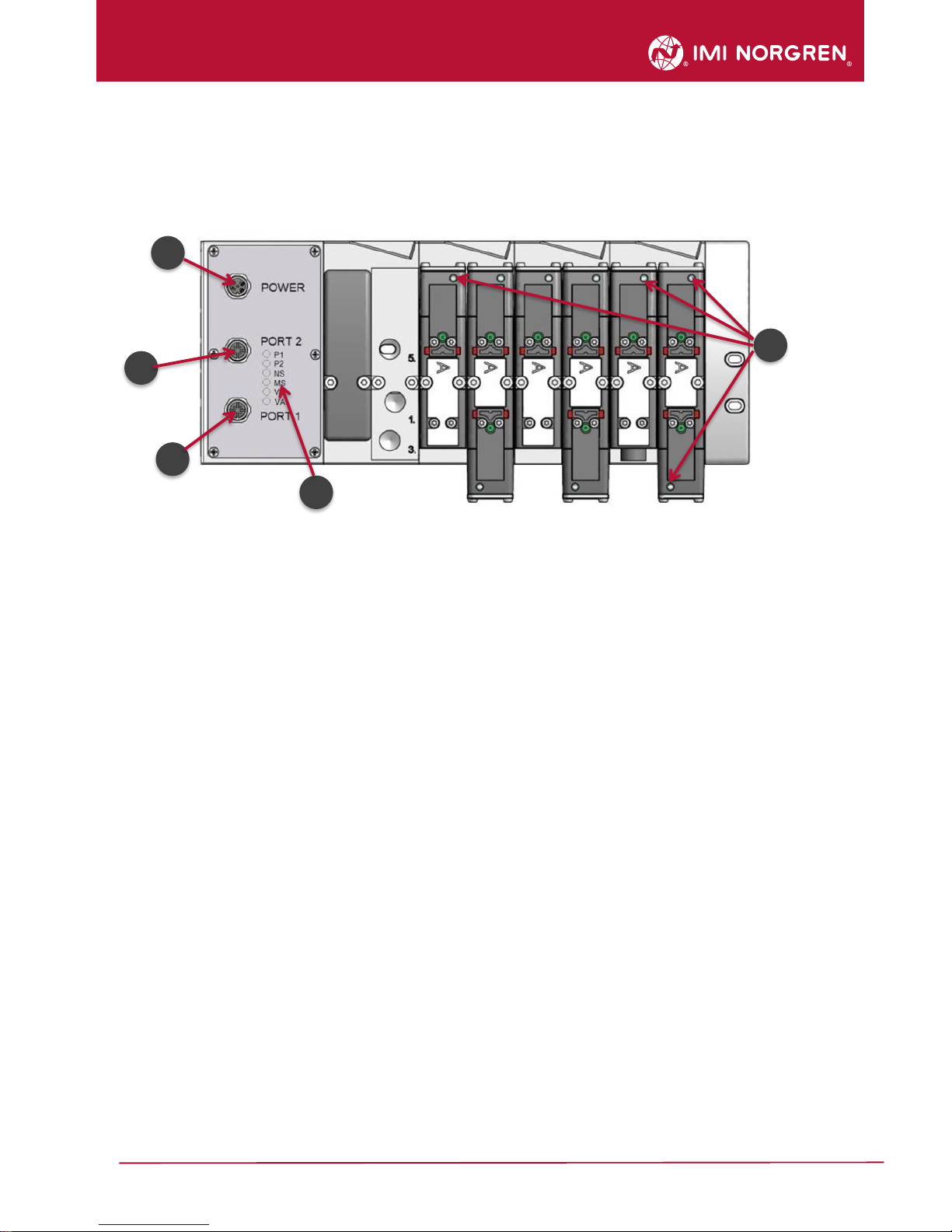
3. Electrical Connections of the VS18/VS26 valve islands
Top view VS18 with 8 stations
1. Port 1 bus connector for EtherNet/IP
(4 pins M12 D-coded female connector)
2. Port 2 bus connector for EtherNet/IP
(4 pins M12 D-coded female connector)
3. Power supply connector
(5-pins M12 A-coded male connector)
4. Status LEDs
5. Valve status LEDs
1
2
5 4 3
12
Operation & Service Manual
Valve islands VS18/VS26 EtherNet/IP
09/2018
Construction & Design is subject to change © 2018 Norgren GmbH
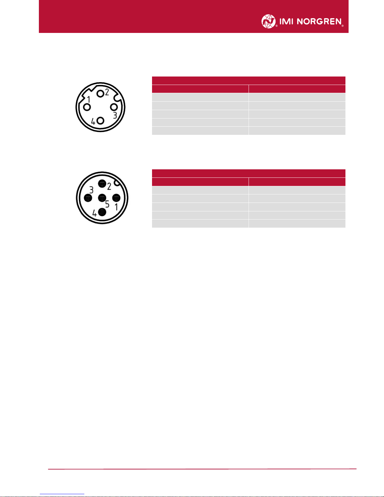
3.1 EtherNet/IP Bus connectors Port 1 & Port 2
M12 / 4 pins / female / D-coded
Pin no.
Function
1
Transmission Data + (TD+)
2
Receive Data + (RD+)
3
Transmission Data - (TD -)
4
Receive Data - (RD -)
Housing
FE (functional earth)
3.2 POWER supply connector
M12 / 5 pins / male / A-coded
Pin no.
Function
1
L1 (VB+) 24V electronics power supply
2
N2 (VA-) 0V valves power supply
3
N1 (VB-) 0V electronics power supply
4
L2 (VA+) 24V valves power supply
5
FE (functional earth)
 Loading...