

IMI NORGREN PGS20, PGS42 User Instructions
PGS20 and PGS42
Series Grippers
User instructions
Auto In-plant

Revisions ECN. NO. BY DAT E
REL 25489 MGF 11/13/08
001 25792 MS 06/23/09
002 25824 MGF 08/04/09
003 25881 RRH 09/25/09
DRAWN DAT E
MFG 10/03/08
CHECKED DAT E
RRH 10/05/09
DES ENG D ATE
JA 10/03/08
APPR, DAT E
DAM 10/05/09
User Instructions for PGS20 and PGS42 Grippers
Table of contents
Section Page
Scope ................................................................................................................ I .......................3
Applicable Documents ...................................................................................... II ....................... 3
Information & Procedures ................................................................................. III .......................3
Cleaning and Maintenance ...............................................................................IV ..................... 10
Specifications ....................................................................................................V .....................10
For internal use only
Revisions record
02
Our policy is one of continued research and development. We therefore reserve the right to amend,
without notice, the specifications given in this document. © 2017 Norgren Automation Solutions, LLC
12680UI REV: 003
2/17

User Instructions for PGS20 and PGS42 Grippers
I. Scope:
This document instructs the operator how to use the IMI Norgren PGS20 and PGS42 Grippers. This user instruction covers
basic gripper set-up and operation, including: port sizes and function, manual unlocking of jaws, jaw replacement, setting
jaw open angle, and accessory mounting.
II. Applicable Documents:
12686SP – Sales Page – PGS20RXXXXXXXXX (Regular Jaw)
12687SP – Sales Page – PGS20FXXXXXXXXX (Flange Jaw)
12688SP – Sales Page – PGS20C/D/EXXXXXXXXX (Chisel Jaw)
12689SP – Sales Page – PGS20S/T/UXXXXXXXXX (Shovel Jaw)
12647SP – Spare Parts List for PGS20 Gripper Series
13213SP – Sales Page – PGS42RXXXXXXXXX (Regular Jaw)
13227SP – Sales Page – PGS42C/D/EXXXXXXXXX (Chisel Jaw)
13284SP – Sales Page – PGS20S/T/UXXXXXXXXX (Shovel Jaw)
13291SP – Sales Page – PGS42FXXXXXXXXX (Flange Jaw)
13214SP – Spare Parts List for PGS42 Gripper Series
III. Procedures:
A. Port Size and Operation
1. Ports are available in 1/8" NPS or 1/8 Rc. The closed port is marked with a “C”.
Gripper close port
Gripper open port
B. Gripper Unlock
1. Release jaw by using a hex key or straight blade screwdriver and pushing on drive pin through slot in side plate
2/17
12680UI REV: 003
Our policy is one of continued research and development. We therefore reserve the right to amend,
without notice, the specifications given in this document. © 2017 Norgren Automation Solutions, LLC
03
User Instructions for PGS20 and PGS42 Grippers
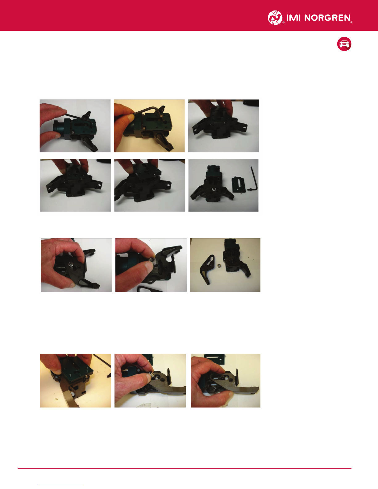
C. Upper Jaw Removal
1. Unlock gripper as shown in step B and remove pad(s) from existing jaws. Set aside for re-assembly.
2. Top jaw should be removed first. Remove SHCS from side plate or indirect sensor. Slide side plate/sensor
retaining pins out of slots in the gripper frame and remove side plate/sensor from gripper. Set SHCS and Side
Plate or Sensor aside for re-assembly
3. Pull jaw upward and o of frame boss and bushing. Remove bushing from cylinder rod and set parts aside.
Flip gripper over to remove lower jaw.
D. Lower Jaw Removal
1. Remove side plate following procedure outlined in earlier section C-2. Some lower jaws (13111, Lower
Flange jaw & 13113, 0 degree. Regular jaw) will require that the cylinder rod be fully extended and bushing
removed prior to removing these jaws. With the cylinder rod in the fully extended position, and bushing
removed, pull lower jaw o of frame boss.
04
Our policy is one of continued research and development. We therefore reserve the right to amend,
without notice, the specifications given in this document. © 2017 Norgren Automation Solutions, LLC
12680UI REV: 003
2/17
 Loading...