


PGS20 and PGS42
Series Grippers
User instructions
Auto In-plant

Revisions ECN. NO. BY DAT E
REL 25489 MGF 11/13/08
001 25792 MS 06/23/09
002 25824 MGF 08/04/09
003 25881 RRH 09/25/09
DRAWN DAT E
MFG 10/03/08
CHECKED DAT E
RRH 10/05/09
DES ENG D ATE
JA 10/03/08
APPR, DAT E
DAM 10/05/09
User Instructions for PGS20 and PGS42 Grippers
Table of contents
Section Page
Scope ................................................................................................................ I .......................3
Applicable Documents ...................................................................................... II ....................... 3
Information & Procedures ................................................................................. III .......................3
Cleaning and Maintenance ...............................................................................IV ..................... 10
Specifications ....................................................................................................V .....................10
For internal use only
Revisions record
02
Our policy is one of continued research and development. We therefore reserve the right to amend,
without notice, the specifications given in this document. © 2017 Norgren Automation Solutions, LLC
12680UI REV: 003
2/17

User Instructions for PGS20 and PGS42 Grippers
I. Scope:
This document instructs the operator how to use the IMI Norgren PGS20 and PGS42 Grippers. This user instruction covers
basic gripper set-up and operation, including: port sizes and function, manual unlocking of jaws, jaw replacement, setting
jaw open angle, and accessory mounting.
II. Applicable Documents:
12686SP – Sales Page – PGS20RXXXXXXXXX (Regular Jaw)
12687SP – Sales Page – PGS20FXXXXXXXXX (Flange Jaw)
12688SP – Sales Page – PGS20C/D/EXXXXXXXXX (Chisel Jaw)
12689SP – Sales Page – PGS20S/T/UXXXXXXXXX (Shovel Jaw)
12647SP – Spare Parts List for PGS20 Gripper Series
13213SP – Sales Page – PGS42RXXXXXXXXX (Regular Jaw)
13227SP – Sales Page – PGS42C/D/EXXXXXXXXX (Chisel Jaw)
13284SP – Sales Page – PGS20S/T/UXXXXXXXXX (Shovel Jaw)
13291SP – Sales Page – PGS42FXXXXXXXXX (Flange Jaw)
13214SP – Spare Parts List for PGS42 Gripper Series
III. Procedures:
A. Port Size and Operation
1. Ports are available in 1/8" NPS or 1/8 Rc. The closed port is marked with a “C”.
Gripper close port
Gripper open port
B. Gripper Unlock
1. Release jaw by using a hex key or straight blade screwdriver and pushing on drive pin through slot in side plate
2/17
12680UI REV: 003
Our policy is one of continued research and development. We therefore reserve the right to amend,
without notice, the specifications given in this document. © 2017 Norgren Automation Solutions, LLC
03
User Instructions for PGS20 and PGS42 Grippers
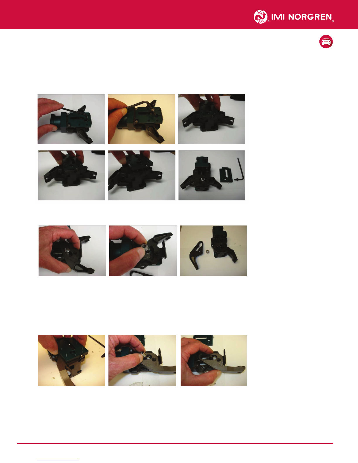
C. Upper Jaw Removal
1. Unlock gripper as shown in step B and remove pad(s) from existing jaws. Set aside for re-assembly.
2. Top jaw should be removed first. Remove SHCS from side plate or indirect sensor. Slide side plate/sensor
retaining pins out of slots in the gripper frame and remove side plate/sensor from gripper. Set SHCS and Side
Plate or Sensor aside for re-assembly
3. Pull jaw upward and o of frame boss and bushing. Remove bushing from cylinder rod and set parts aside.
Flip gripper over to remove lower jaw.
D. Lower Jaw Removal
1. Remove side plate following procedure outlined in earlier section C-2. Some lower jaws (13111, Lower
Flange jaw & 13113, 0 degree. Regular jaw) will require that the cylinder rod be fully extended and bushing
removed prior to removing these jaws. With the cylinder rod in the fully extended position, and bushing
removed, pull lower jaw o of frame boss.
04
Our policy is one of continued research and development. We therefore reserve the right to amend,
without notice, the specifications given in this document. © 2017 Norgren Automation Solutions, LLC
12680UI REV: 003
2/17

User Instructions for PGS20 and PGS42 Grippers
E. Jaw Replacement
Applicable jaws: (13102, 13113, 13114, 13111, 13100, 13100-01, 13100-02,
10607, 10607-01, 10607-02, 13112, 13112-01, 13112-02, 13978 & 13987)
1. For lower jaws: Apply Mobilux grease or equivalent to both flat surfaces of cam, as well as the surface of the
frame core, pivot boss, and drive pin. Align pivot hole in cam with boss and drive pin with the bottom side of the
cam slot. Slide jaw over boss and onto gripper. Place bushing over pin and into cam slot radii side facing
cylinder rod. Seat bushing firmly against cylinder rod and ensure that the bushing rotates freely.
Drive pin
Pivot boss
Radius
Bushing
Seat Bushing
against cylinder rod
2. Install side (cam retainer) plate: With the Side Plate approximately parallel to the gripper frame, align pins of
side plate with slots in frame. Side plate will slide diagonally toward gripper frame as pins follow the slots in the
frame. Continue to move side plate toward frame until guide pins are fully seated in the frame slots.
3. Clean M6 X 10 mm SHCS for side plate. Apply liquid Loctite 262 or equivalent to pivot hole in frame. Insert screw
through side plate and into frame. Tighten M6 SHCS to 120 in-lb.
2/17
12680UI REV: 003
Our policy is one of continued research and development. We therefore reserve the right to amend,
without notice, the specifications given in this document. © 2017 Norgren Automation Solutions, LLC
05

User Instructions for PGS20 and PGS42 Grippers
F. Setting Jaw Open Angle (if required)
1. The PGS20 gripper has three possible jaw open positions; full open (no bumper), 45 degrees, and 22 degrees.
Jaw open angle is set by installing the appropriate bumper into the frame in the slots provided, prior to installing
the upper cam. Two bumpers are available for the gripper a thin bumper marked “45” (13150) provides a 45
degree stop, and a thick bumper marked “22” (13152) for 22 degree stop angle.
2. To set the open stop angle, remove SHCS from side plate or indirect sensor, and remove side plate/sensor as
described in step C)-2). Set SHCS and Side Plate/Sensor aside for re-assembly. Remove jaw from gripper. Locate
and insert the appropriate bumper into the slots provided near the front of the gripper frame by sliding the bumper
sideways into the slots until it is fully seated, and flush with the side of the frame core.
22° Open Jaw Angle Uses
22 degree (thick) stop
45° Open Jaw Angle Uses
45 degree (thin) stop
Full Open Jaw Angle
Bumper not used
Figure 1
3. To remove the jaw open stop insert a 5mm hex wrench into the hole provided in the stop bumper. Pull up on the
bumper until it is clear of the gripper frame.
06
Our policy is one of continued research and development. We therefore reserve the right to amend,
without notice, the specifications given in this document. © 2017 Norgren Automation Solutions, LLC
12680UI REV: 003
2/17

User Instructions for PGS20 and PGS42 Grippers
4. For upper jaws: Flip gripper over and apply Mobilux grease or equivalent to both flat surfaces of cam, as well as
the surface of the frame core, pivot boss, and drive pin. Insure the jaw open stop is installed if required per section
F. Align pivot hole in cam with boss and drive pin with the bottom side of the cam slot. Slide jaw over boss and
onto gripper. Place bushing over pin and into cam slot radii side facing cylinder rod. Seat bushing firmly against
cylinder rod.
G. Installing an Indirect Sensor
1. Installing an Indirect Sensor: An Indirect Sensors mounts in place of one of the standard side plates. Move
brass bushing in sensor to align with drive pin in gripper. This must be done to correctly install sensor. Align pins of
sensor with slots in frame. Sensor will slide diagonally toward gripper frame as pins follow the slots in the frame.
Continue to move sensor toward frame until guide pins are fully seated in the frame slots. As the sensor seats into
the frame, make sure bushing and drive pin are still aligned.
Note: Whenever any part of the gripper is replaced
2/17
12680UI REV: 003
Our policy is one of continued research and development. We therefore reserve the right to amend,
without notice, the specifications given in this document. © 2017 Norgren Automation Solutions, LLC
07

User Instructions for PGS20 and PGS42 Grippers
2. Clean M6 X 30 mm SHCS for sensor. Apply liquid Loctite 262 or equivalent to pivot hole in frame. Insert screw
through sensor and into frame. Tighten the M6 SCHS 120in-lb.
H. Calibrating In-Direct Sensor
Sensor must be calibrated whenever any part of the gripper is replaced including pads.
1) Part Present
a) To program the sensor for a particular material thickness, apply air to the gripper and grip on the material
thickness which is to be used for the particular job. With an object such as a small Allen wrench, press the
button until the Red LED corresponding to the material range of the job lights as shown on the label.
b) Verify calibration:
(1) Close the gripper with no material between the pads. The LED should be o.
(2) Close the gripper on a single blank of material. The Red LED corresponding to your material range should
be on.
2) Double Blank
a) To program the sensor for a particular material thickness, apply air to the gripper and grip on the material
thickness which is to be used for the particular job. With an object such as a small Allen wrench, press the
button until the Red LED(s) corresponding to the material range of the job lights as shown on the label.
b) Verify calibration:
(1) Close the gripper with no material between the pads. The LED(s) should be o.
(2) Close the gripper on a single blank of material. The Red LED(s) corresponding to you material range
should be on.
Note: double blank sensor not available on flange jaw gripper
08
Our policy is one of continued research and development. We therefore reserve the right to amend,
without notice, the specifications given in this document. © 2017 Norgren Automation Solutions, LLC
12680UI REV: 003
2/17

User Instructions for PGS20 and PGS42 Grippers
I. Installing an In-Pad Sensor
1) If an In-Pad Sensor is to be installed, it goes on top of the side plate assembly. Wrap sensor cable through holder
and align holes on side plate. Clean and apply liquid Loctite 262 or equivalent to 2X M5 X 10 mm SHCS and thread
thru sensor into side plate. Tighten both SHCS to 36in-lb.
2) Apply liquid Loctite 262 or equivalent to sensor bolt, place thru jaw and tighten 120in-lb.
J.
Cable should follow the contour of the gripper jaw
Cable storage loop can be adjusted with a push/pull motion
to provide more or less cable slack in gripper jaw area.
2/17
12680UI REV: 003
Our policy is one of continued research and development. We therefore reserve the right to amend,
without notice, the specifications given in this document. © 2017 Norgren Automation Solutions, LLC
09

User Instructions for PGS20 and PGS42 Grippers
Pad Replacement
1) Unlock jaws on gripper as outlined in section B & open jaws to get access to pads. Side plates or sensors DO NOT
need to be removed.
2) Remove M6 X 10 mm SHCS from jaw then remove pad.
3) Apply liquid Loctite 262 or equivalent to M6 X 10 mm SHCS and insert into one of the jaws. Insert replacement pad
into the opposite side of the jaw. Thread SHCS into pad and tighten to 120in-lb. Repeat step for other jaw. Chisel
and Shovel jaws only require one pad
IV. Cleaning and Maintenance:
A) Remove excess grease from outer surfaces of gripper.
B) No required maintenance.
V. Specifications:
Gripper Throat Depth Flange Height Working Pressure Grip Force Actuation Time
PGS20C/S 1.24 (31.6 mm) 1.49 (37.8 mm) 60psi (413kPa) Min. –
100psi (689 kPa) Max.
PGS20D/T 1.24 (31.6 mm) 1.49 (37.8 mm) 60psi (413kPa) Min. –
100psi (689 kPa) Max.
PGS20E/U 1.24 (31.6 mm) 1.49 (37.8 mm) 60psi (413kPa) Min. –
100psi (689 kPa) Max.
PGS20F 1.65 (42.0 mm) 1.42 (36.1 mm) 60psi (413kPa) Min. –
100psi (689 kPa) Max.
PGS20R 1.20 (30.6 mm) 1.82 (46.2 mm) 60psi (413kPa) Min. –
100psi (689 kPa) Max.
PGS42C/S 1.24 (31.6 mm) 1.49 (37.8 mm) 60psi (413kPa) Min. –
100psi (689 kPa) Max.
PGS42D/T 1.24 (31.6 mm) 1.49 (37.8 mm) 60psi (413kPa) Min. –
100psi (689 kPa) Max.
PGS42E/U 1.24 (31.6 mm) 1.49 (37.8 mm) 60psi (413kPa) Min. –
100psi (689 kPa) Max.
PGS42F 1.65 (42.0 mm) 1.42 (36.1 mm) 60psi (413kPa) Min. –
100psi (689 kPa) Max.
PGS42R 1.20 (30.6 mm) 1.82 (46.2 mm) 60psi (413kPa) Min. –
100psi (689 kPa) Max.
Up to 450lbs (200kgf)
@ 80psi (551kPa)
Up to 450lbs (200kgf)
@ 80psi (551kPa)
Up to 450lbs (200kgf)
@ 80psi (551kPa)
Up to 450lbs (200kgf)
@ 80psi (551kPa)
Up to 450lbs (200kgf)
@ 80psi (551kPa)
Up to 900lbs (400kgf)
@ 80psi (551kPa)
Up to 900lbs (400kgf)
@ 80psi (551kPa)
Up to 900lbs (400kgf)
@ 80psi (551kPa)
Up to 900lbs (400kgf)
@ 80psi (551kPa)
Up to 900lbs (400kgf)
@ 80psi (551kPa)
.050±.010 sec close /
<.090 sec open
.050±.010 sec close /
<.090 sec open
.050±.010 sec close /
<.090 sec open
.050±.010 sec close /
<.090 sec open
.050±.010 sec close /
<.090 sec open
.063±.010 sec close /
<.100 sec open
.063±.010 sec close /
<.100 sec open
.063±.010 sec close /
<.100 sec open
.063±.010 sec close /
<.100 sec open
.063±.010 sec close /
<.100 sec open
10
Our policy is one of continued research and development. We therefore reserve the right to amend,
without notice, the specifications given in this document. © 2017 Norgren Automation Solutions, LLC
12680UI REV: 003
2/17

User Instructions for PGS20 and PGS42 Grippers
Without In-Pad Sensor
Chisel jaw / shovel jaw Regular / flange jaw
Material
thickness
Pad
color
Fixed jaw
color
Jaw 1
pad color
Jaw 2
pad color
0.50 mm to 2.50 mm Black Black Silver Black
2.51 mm to 4.50 mm Silver Black Silver Silver
4.51 mm to 6.50 mm Black Silver Silver Gold
6.51 mm to 8.50 mm Silver Silver n/a n/a
8.51 mm to 10.50 mm Black Gold n/a n/a
With In-Pad Sensor
Chisel jaw / shovel jaw Regular / flange jaw
Material
thickness
Shim
usage
Fixed jaw
color
Jaw 1
pad color
Jaw 2
pad color
0.50 mm to 2.50 mm Shim Black In-Pad (Silver) Black
2.51 mm to 4.50 mm No Shim Black In-Pad (Silver) Silver
4.51 mm to 6.50 mm Shim Silver In-Pad (Silver) Gold
6.51 mm to 8.50 mm No Shim Silver n/a n/a
8.51 mm to 10.50 mm Shim Gold n/a n/a
Warning
Improper selection, misuse, age or malfunction of components used in
systems can cause failure in various modes. The system designer is warned
to consider the failure modes of all component parts and to provide adequate
safeguards to prevent personal injury or damage to equipment or property
in the event of such failure modes. System designers and end users are
cautioned to consult instruction sheets and specifications available from the
factory. The system designer/end user is responsible for verifying that all
requirements for the application are met.
Proposition 65: These products may contain chemicals known to the state of
California to cause cancer, or birth defects, or other reproductive harm.
2/17
12680UI REV: 003
Our policy is one of continued research and development. We therefore reserve the right to amend,
without notice, the specifications given in this document. © 2017 Norgren Automation Solutions, LLC
Warranty
The products described herein are warranted subject to seller’s Standard
Terms and Condition of Sale, available at seller’s website.
11
 Loading...