

IMI NORGREN L64C, L64M Installation & Maintenance Instructions Manual
ADJUSTMENT
1. Turn on system pressure.
2. Adjust lubricator drip rate only when there is a constant
rate of air flow through the lubricator. Monitor drip rate
through sight feed dome (3).
3. Oil-Fog Lubricators - Determine the average rate of flow
through the lubricator. Turn green knob (3) to obtain one
drop per minute for each 5 dm
3
/s (10 scfm). For
example, if the average flow is 19 dm
3
/s (40 scfm), set
the drip rate at 4 drops per minute. Turn knob
counterclockwise to increase and clockwise to decrease
the drip rate. The oil feed setting can be locked by
pushing the lock ring down, this must be released before
adjustment by pulling up.
4. Micro-Fog Lubricators - Oil drip rate is adjusted by the
red knob above the sight-feed dome, counterclockwise to
increase and clockwise to decrease the drip rate. The rate
changes automatically to compensate for flow variations.
The oil feed setting can be locked by pushing the lock
ring down, this must be released before adjustment by
pulling up.
See Drip Rate Chart. Turn knob counterclockwise to
increase and clockwise to decrease the drip rate.
Drip Rate Chart for Micro-Fog Lubricators
Flow - dm
3
/s (scfm) Drops per Minute
2,4 (5) 10
5 (10) 11
9 (20) 13
14 (30) 15
19 (40) 17
24 (50) 19
28 (60) 22
34 (70) 24
38 (80) 26
43 (90) 28
48 (100) 30
5. Monitor the device being lubricated for a few days
following initial adjustment. Adjust the drip rate if the oil
delivery at the device appears either excessive or low.
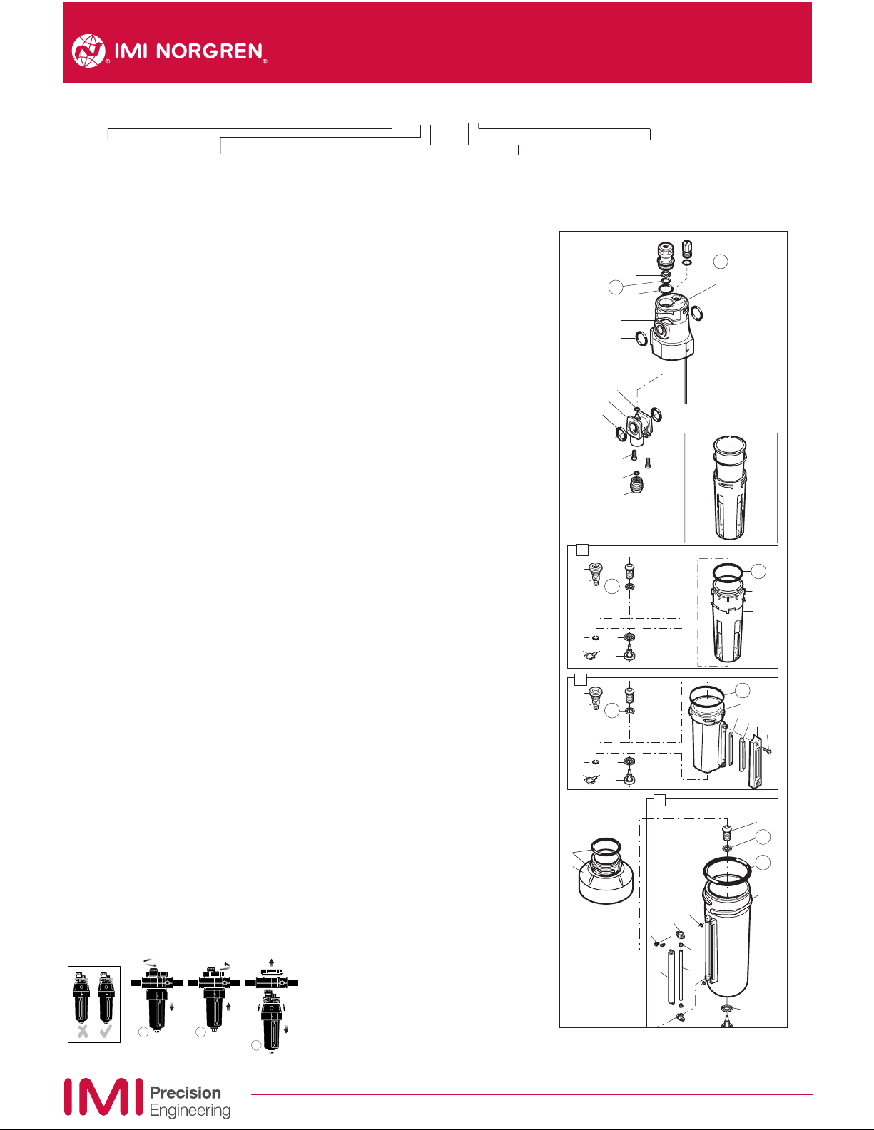
DISASSEMBLY
1. Shut off inlet pressure. Reduce pressure in inlet and
outlet lines to zero. Loosen fill plug (1).
2. Remove reservoir - push into body and turn
counterclockwise.
3. Disassemble in general accordance with the item
numbers on exploded view. Do not remove the manual
drain unless replacement is necessary. Remove and
replace drain assembly only if drain malfunctions. Do not
remove syphon tube (53). Remove and replace items 54
through 59 only if lubricator malfunctions.
CLEANING
1. Clean plastic reservoir with warm water only. Clean other
parts using warm water and soap.
2. Dry parts. Blow out internal passages in body with clean,
dry compressed air.
3. Inspect parts. Replace parts found to be damaged. If
plastic reservoir shows signs of cracking or cloudiness,
replace with a metal reservoir.
ASSEMBLY
1. Lubricate o-rings, the portion of the manual drain body
(19, 33) that contacts the bowl, and the hole in the
manual drain body that accommodates the stem of drain
valve (20, 34) with o-ring grease.
2. Assemble lubricator as shown on exploded view.
3. Assemble the 1 litre (1 quart) liquid indicator parts (69
through 74) to reservoir. Apply a 0,9 to 1,8 kg (2 to 4
pound) clamping force to upper and lower sight glass
brackets (70). Tighten screws (69).
3. Torque Table N-m (Inch-Pounds)
3 (Dome) 2,3 to 2,8 (20 to 25)
43 (Screw) 1,7 to 2,3 (15 to 20)
55 (Screw) 1,1 to 1,6 (10 to 14)
69 (Screw) 0,9 to 1,1 (8 to 10)
4. Push reservoir, or reservoir with guard, into body and
turn fully clockwise.
TECHNICAL DATA
Fluid: Compressed air
Maximum pressure:
Guarded transparent bowl: 10 bar (150 psig)
Metal bowl: 17 bar (250 psig)
Operating temperature*:
Transparent bowl: –20° to +50°C (0° to +125°F)
Metal bowl: –20° to +80°C (0° to +175°F)
* Air supply must be dry enough to avoid ice formation at
temperatures below +2°C (+35°F).
Start point (minimum flow required for lubricator
operation) at 6,3 bar (90 psig) inlet pressure:
1,5 dm
3
/s (3.2 scfm)
Nominal bowl capacity: 0,2 litre (7 fluid oz), standard
1 litre (1 quart US), optional
Materials:
Body: Zinc
Bowl:
Metal: Aluminium
Transparent, optional: Polycarbonate
Metal bowl liquid level indicator lens,
standard: Grilamid
Metal bowl sight glass, optional (standard on
1 litre bowl): Pyrex
Sight dome: Polycarbonate
Elastomers: Synthetic rubber
REPLACEMENT ITEMS
Service kit, contains required items circled: ..........4382-200
Prismatic sight glass..............................................4380-042
Pyrex sight glass....................................................4380-041
Pyrex sight glass, 1 litre bowl..................................2273-22
Manual drain ..............................................................684-84
INSTALLATION
1. Install unit vertically in air line -
● vertically (bowl down),
● with air flow in direction of arrow on body,
● upstream of cycling valves
● as close as possible to the device being lubricated,
● Oil-Fog Models - Not more than 5,2m (15 feet) from
the device being lubricated, and at the same height or
higher than the device.
2. Before assembling the basic unit into the yoke the port
seal o-rings should be lightly smeared with o-ring
grease.
3. Locate clamp ring under lugs on top of yoke, offer basic
unit into yoke with directional arrows correctly aligned
(an interference fit prevents assembly if misaligned)
before engaging and fully tightening the clamp ring.
4. Turn bowl or bowl guard fully clockwise into body before
pressurizing. Lock symbols on body and bowl guards
must align.
………continued over
L64★ - ★★P- ★★N
Port
2.....1/4"
3.....3/8"
4.....1/2"
6.....3/4"
Thread
A ....PTF
B ....ISO Rctaper
G ....ISO G parallel
N ....No thread (basic unit)
Bowl/Reservoir
A ....optional 1 litre (1 quart US) metal
D ....Metal
P ....Transparent with guard
R ....Metal with Pyrex liquid level indicator
Operation
C ....Oil-Fog
M ...Micro-Fog
Drain
M ...Manual
E.....No drain (Closed bowl)
Q ....Manual 1/4 turn
R ....Remote fill
A
B
C
L64C, L64M - Lubricator
Installation & Maintenance Instructions
RECOMMENDED LUBRICANTS
Fill reservoir with a good quality, light, misting type oil
for comp
ressed air tools. See our publication
N/AL.8.900.935. Fill to maximum fill line on transparent
voirs. Oil level must always be visible in lens on metal
reser
reservoirs. Do not overfill.
FILL RESERVOIR (OIL-FOG LUBRICATORS)
Remove fill plug (1), add oil, and reinstall fill plug. Fill
plug can be removed and oil added without shutting off air
pressure to the lubricator
FILL RESERVOIR (MICRO-FOG LUBRICATORS)
Shut off inlet air pressure and reduce pressure in
reservoir to zero. Remove fill plug (1), add oil, and reinstall
fill plug. Do not remove the fill plug when the reservoir is
pressurized, as oil will blow out the fill plug hole.
.
61
60
3
4
5
6
8
9
56
54
57
55
59
58
18
22
19
25
24
21
20
23
32
36
33
39
38
35
34
37
62
71
70
69
72
1
2
7
9
53
Early Plastic Bowl
and Guard.
No Longer Available
Replaced by Item 18
Current Plastic Bowl
47
48
46
45
74
73
67
31
30
29
44
43
65
68
64
63
Our policy is one of continued research and development. We therefore reserve the right to amend, without notice,
the specifications given in this document. © 1999 Norgren, Inc.
IM-240.400
(7/99)

WARNING
These
products are intended for use in industrial
compressed air systems only. Do not use these products
where pressures and temperatures can exceed those listed
under Technical Data.
Polycarbonate plastic bowls can be damaged and
possibly burst if exposed to such substances as certain
solvents, strong alkalies, compressor oils containing esterbased additives or synthetic oils. Fumes of these
substances in contact with the polycarbonate bowl,
externally or internally, can also result in damage. Clean
with warm water only.
Use metal bowl in applications where a plastic bowl
might be exposed to substances that are incompatible with
polycarbonate.
Before using these products with fluids other than air, for
non industrial applications, or for life-support systems
consult IMI Precision Engineering.
L64C, L64M - Lubricator
Installation & Maintenance Instructions
Our policy
is one of continued research and development. We therefore reserve the right to amend, without notice,
the specifications given in this document. © 1999 Norgren, Inc.
IM-240.400
(7/99)
 Loading...