

IMI NORGREN F68H, F68C Installation & Maintenance Instructions Manual
F68C, F68H Oil removal filter
Installation & Maintenance Instructions
Option selector
Bowl
C Standard
H High flow
Port
4* 1/2”
6 3/4“
8 1“
N No yoke
* Only available with the F68C standard filter. ** See Norgren publication IM-900.920 for specifications and electrical wire connections of the optional electric service indicator.
Thread
A PTF
B ISO Rc tapered
G ISO G parallel
N No yoke
Options
D With mechanical service life indicator
E With electrical service life indicator*
N No service life indicator
F68˙ – ˙˙˙ – ˙˙˙
Drain
A Automatic
E Closed bottom
M Manual, spindle type
Q Manual, 1/4 turn
Bowl
C 1 litre (1 quart) no liquid indicator
M 0,5 litre (1 pint) no liquid indicator
R 0,5 litre (1 pint) with liquid indicator
U 1 litre (1 quart) With liquid indicator
Technical features
Technical Data
Fluid: Compressed air
Maximum pressure: 17 bar (250 psig)
Operating temperature*:
-20° ... +65°C (0° ... +150°F)
* Air supply must be dry enough to avoid ice
formation at temperatures below +2°C (+35°F).
Partical removal: 0,01 µm
Air quality: Within ISO 8573-1, Class 1
(particulates) and Class 2 (oil content).
Maximum remaining oil content: 0,01 mg/m3 at
+20°C (+70°F) with an inlet concentration
of 17 mg/m3.
Maximum flow at 6,3 bar (90 psig) inlet pressure
to maintain stated oil removal performance:
1/2” ports: 35 dm3/s (74 scfm)
3/4” ports: 35 dm3/s (74 scfm)
1” ports: 60 dm3/s (127 scfm)
1/4 turn manual drain connection: 1/8” pipe
thread
Automatic drain connection: 1/8” pipe thread
Automatic drain operating conditions (float
operated)
Bowl pressure required to close drain:
Greater than 0,3 bar (5 psig)
Bowl pressure required to open drain:
Less than 0,2 bar (3 psig)
Minimum air flow required to close drain:
1 dm3/s (2 scfm)
Manual operation: Depress pin inside drain
outlet to drain bowl
Nominal bowl size:
0,5 litre (1 pint U.S.)
1 litre (1 quart U.S.)
Materials:
Body: Aluminium
Yoke: Aluminium
Bowl: Aluminium
Liquid level indicator: Pyrex
Element: Synthetic fibre and polyurethane foam
Elastomers: Synthetic rubber
Service life indicator:
Body: Transparent nylon
Internal parts: Acetal
Spring: Stainless steel
Elastomers NBR
Replacement Items
Service kit
(items circled on exploded view)
4380-301
0.5 litre bowl liquid level lens (19 thru 27)
4380-060
1 litre bowl liquid level lens (30 thru 38)
4380-061
Filter element, standard, short (53) 5351-08
Filter element, high flow, long (53) 5351-03
Automatic drain, G1/8 outlet (49) 3000-97
Automatic drain, 1/8 PTF outlet (49) 3000-10
Manual drain, spindle type (44) 684-84
Manual drain, 1/4 turn (40) 619-50
Mechanical service life indicator (1) 5797-50
Electrical service life indicator (6) 4020-51R
Installation
1. Install yoke in air line -
• with air ow in direction of arrow on top of
yoke,
• upstream of regulators, lubricators, and
cycling valves,
• as close as possible to the air supply when
filter is used as a main line filter,
• as close as possible to the device being
serviced when filter is used as a final filter.
2. Connect piping to yoke ports using pipe
thread sealant on male threads only.
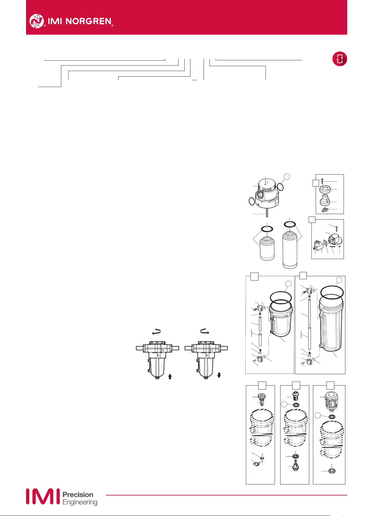
3. Lubricate o-rings (15) with a light coat of
o-ring grease, then place o-rings in grooves
in body (14).
4. Place clamp ring under lugs on top of yoke.
5. Make sure arrows on yoke and filter point in
same direction, then plug filter into yoke and
tighten clamp ring hand tight.
6. Turn bowl into body until arrowhead on bowl
is aligned with or to the right of the
arrowhead on the body.
7. Flexible tube with 3mm (0.125”) minimum I.D.
can be connected to the automatic drain.
Avoid restrictions in the tube.
8. Install a Norgren general purpose filter with a
5 µm element upstream of the oil removal
filter to obtain maximum element service life.
Servicing
1.Open manual drain to expel accumulated
liquids. Keep liquids below element (53).
2. Replace filter element when pressure drop
across element exceeds 0,7 bar (10 psig).
The mechanical service life indicator shows
approximately all red and the optional
electrical service life indicator provides an
electrical output when pressure drop across
the element reaches 0,7 bar (10 psig)
Diassembly
1. Shut o inlet pressure. Reduce pressure in
inlet and outlet lines to zero.
2. Unscrew the clamp ring and remove filter
from yoke.
3. Disassemble in general accordance with the
item numbers on exploded view. Do not
remove the drains
or the service indicators unless replacement
is necessary. Remove and replace only if they
malfunction. Do not attempt to remove rod
(54), as it is cemented to body.
15
14
54
53
18
21
20
19
22
24
25
26
22
23
20
19
40
43
42
41
28
21
47
48
45
46
27
Element
0 Coalescing
53
29
31
30
33
35
36
37
33
34
31
30
44
1
6
1112
32
51
52
50
2
4
3
5
7
8
9
13
10
38
39
32
49
Our policy is one of continued research and development. We therefore reserve the right to amend,
without notice, the specifications given in this document. (1999 - I&M8089d) © 2015 IMI International s.r.o.
7/15
I&M/en 8.260.105.01
F68C, F68H Oil removal filter
Installation & Maintenance Instructions
Cleaning
1. Element (53) cannot be cleaned. Clean lens
(3, 24, 35) with warm water only. Do not
submerge electrical service indicator (6) in
water. Clean indicator (6) with dry, clean
cloth. Clean other parts with warm water
and soap.
2. Rinse and dry parts. Blow out internal
passages in body (14) with clean, dry
compressed air.
3. Inspect parts. Replace those found to be
damaged.
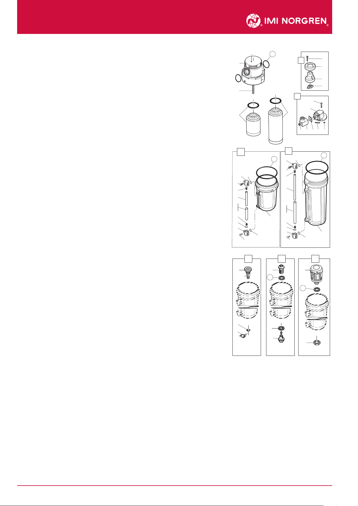
Assembly
1. Lubricate o-rings, the portion manual drain
body (43) that contacts the bowl, and the
hole in the manual drain body that accom
modates the stem of drain valve (41) with
o-ring grease.
2. Assemble the unit as shown on the exploded
view.
3. Assemble the liquid indicator parts (19 thru
26, 30 thru 37) to reservoir. Apply a 0.9 to
1.8 kg (2 to 4 pound) clamping force to
upper and lower sight glass brackets (20,
31). Tighten screws (19, 30).
4. Arrows on indicator (3, 8) and body (14) must
point in same direction.
5. Torque Table
Item Torque in N-m (Inch-Pounds)
2, 7 (Screw) 2,8 ... 3,9 (25 ... 34)
19, 30 (Screw) 1,8 ... 2,3 (16 ... 20)
45, 50 (Nut)0, 8 ... 1,2 (7 ... 10)
53 (Element) 5 ... 6,2 (44 ... 55)
6. Turn bowl into body until arrowhead on bowl
is aligned with or to the right of the arrow
head on the body.
Caution
Water vapor will pass through these units and
could condense into liquid form downstream as
air temperature drops. Install an air dryer if water
condensation could have a detrimental eect on
the application.
WARNING
These products are intended for use in industrial
compressed air systems only. Do not use these
products where pressures and temperatures can
exceed those listed under Technical Data.
Before using these products with fluids other
than air, for non industrial applications, or for
life-support systems consult Norgren.
Use in potentially explosive atmospheres
Code of device according EC directive 94/9/EC
Ex II 2 GD c TX
• Only non-ammable gasese to be used as a
medium.
• Surface temperature dependant on process
fluid temperature and ambient temperature
- must be below the ignition temperature of the
flammable gas or dust.
• Earth unit and/or pipework to avoid
electrostatic discharge.
• Precautions should be taken to prevent hazard
from adiabatic compression.
• Use wet cloth for cleaning.
• Protect the unit from object falling onto it.
• Avoid contact with corrosive environment.
• For servicing the unit it is recommended to
carry out this work outside of the danger
zone.
• For details of ignition hazard assessment
contact Norgren.
15
14
54
53
18
27
31
21
20
19
22
24
25
26
22
23
20
21
19
40
43
42
41
30
33
35
28
33
34
44
47
48
45
46
1
6
53
1112
29
32
36
37
31
30
51
52
50
2
4
3
5
7
8
9
13
10
38
39
32
49
I&M/en 8.260.105.02
Our policy is one of continued research and development. We therefore reserve the right to amend,
without notice, the specifications given in this document. (1999 - I&M8089d) © 2015 IMI International s.r.o.
7/15
 Loading...