

IMI Cornelius, Inc. IDC 255 Installation Manual
IDC 255 Progate Drive Thru Installation Manual
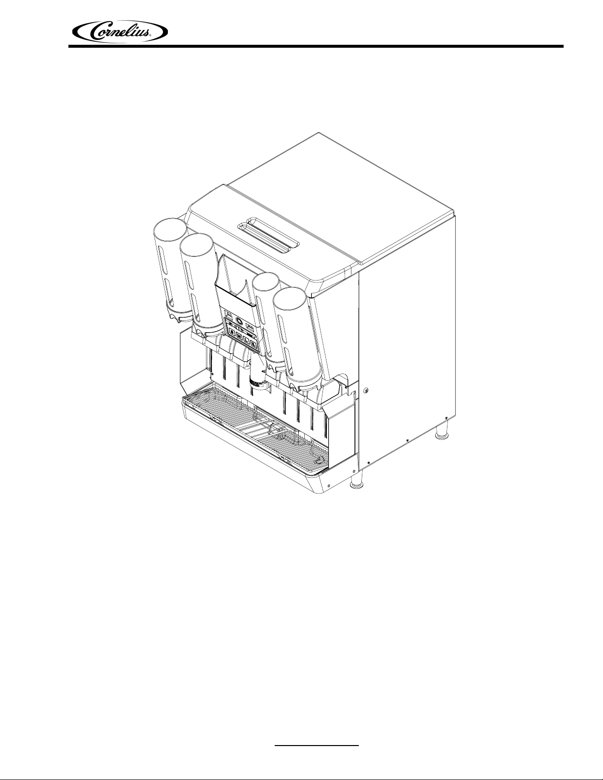
INSTALLATION MANUAL
IDC 255 PROGATE DRIVE THRU UNIT
Release Date: December 31, 2008 www.cornelius.com Revision: B

IDC 255 Progate Drive Thru Installation Manual
Publication Number: 621057419INS - 2 - © 2006, IMI Cornelius Inc.

IDC 255 Progate Drive Thru Installation Manual
Safety Instructions. . . . . . . . . . . . . . . . . . . . . . . . . . . . . . . . . . . . . . . . . . . . . . . . . . . . . . . . . . . . . . . . 1
Read and Follow all Safety Instructions. . . . . . . . . . . . . . . . . . . . . . . . . . . . . . . . . . . . . . . . . . . . . . 1
Recognize Safety Alerts. . . . . . . . . . . . . . . . . . . . . . . . . . . . . . . . . . . . . . . . . . . . . . . . . . . . . . . 1
Different Types of Alerts. . . . . . . . . . . . . . . . . . . . . . . . . . . . . . . . . . . . . . . . . . . . . . . . . . . . . . . 1
Safety Tips . . . . . . . . . . . . . . . . . . . . . . . . . . . . . . . . . . . . . . . . . . . . . . . . . . . . . . . . . . . . . . . . . 1
Qualified Service Personnel. . . . . . . . . . . . . . . . . . . . . . . . . . . . . . . . . . . . . . . . . . . . . . . . . . . . 1
CO2 (Carbon Dioxide) Warning . . . . . . . . . . . . . . . . . . . . . . . . . . . . . . . . . . . . . . . . . . . . . . . . . 1
Shipping And Storage . . . . . . . . . . . . . . . . . . . . . . . . . . . . . . . . . . . . . . . . . . . . . . . . . . . . . . . . 1
Unit Specification. . . . . . . . . . . . . . . . . . . . . . . . . . . . . . . . . . . . . . . . . . . . . . . . . . . . . . . . . . . . . . . . . 2
Description . . . . . . . . . . . . . . . . . . . . . . . . . . . . . . . . . . . . . . . . . . . . . . . . . . . . . . . . . . . . . . . . . . . . 2
Valve Configurations . . . . . . . . . . . . . . . . . . . . . . . . . . . . . . . . . . . . . . . . . . . . . . . . . . . . . . . . . . . . 2
Specification. . . . . . . . . . . . . . . . . . . . . . . . . . . . . . . . . . . . . . . . . . . . . . . . . . . . . . . . . . . . . . . . . . . 2
Progate 2 Features . . . . . . . . . . . . . . . . . . . . . . . . . . . . . . . . . . . . . . . . . . . . . . . . . . . . . . . . . . 3
Progate Portion Ice Control Features. . . . . . . . . . . . . . . . . . . . . . . . . . . . . . . . . . . . . . . . . . . . . . . . . 3
Lid Dispenser . . . . . . . . . . . . . . . . . . . . . . . . . . . . . . . . . . . . . . . . . . . . . . . . . . . . . . . . . . . . . . . . . . . 3
Straw Holder . . . . . . . . . . . . . . . . . . . . . . . . . . . . . . . . . . . . . . . . . . . . . . . . . . . . . . . . . . . . . . . . . . . 3
Installation . . . . . . . . . . . . . . . . . . . . . . . . . . . . . . . . . . . . . . . . . . . . . . . . . . . . . . . . . . . . . . . . . . . . . . 4
Mounting and Placement . . . . . . . . . . . . . . . . . . . . . . . . . . . . . . . . . . . . . . . . . . . . . . . . . . . . . . . . . 4
Adjust Carbonator CO2 Regulator and Turn Water Inlet Supply Line ON. . . . . . . . . . . . . . . . . . . . 6
CO2 Installation . . . . . . . . . . . . . . . . . . . . . . . . . . . . . . . . . . . . . . . . . . . . . . . . . . . . . . . . . . . . . . . . 7
Power Installation. . . . . . . . . . . . . . . . . . . . . . . . . . . . . . . . . . . . . . . . . . . . . . . . . . . . . . . . . . . . . . . 7
Water Installation . . . . . . . . . . . . . . . . . . . . . . . . . . . . . . . . . . . . . . . . . . . . . . . . . . . . . . . . . . . . . . . 8
To access cold plate water inlets . . . . . . . . . . . . . . . . . . . . . . . . . . . . . . . . . . . . . . . . . . . . . . . . 8
Operation Instructions . . . . . . . . . . . . . . . . . . . . . . . . . . . . . . . . . . . . . . . . . . . . . . . . . . . . . . . . . . . . 9
Lid Dispenser Operation . . . . . . . . . . . . . . . . . . . . . . . . . . . . . . . . . . . . . . . . . . . . . . . . . . . . . . . . . 9
Unit Operation . . . . . . . . . . . . . . . . . . . . . . . . . . . . . . . . . . . . . . . . . . . . . . . . . . . . . . . . . . . . . . . . . 9
Loading of Lid Dispenser . . . . . . . . . . . . . . . . . . . . . . . . . . . . . . . . . . . . . . . . . . . . . . . . . . . . . . . . 10
Plastic Wrapped lids. . . . . . . . . . . . . . . . . . . . . . . . . . . . . . . . . . . . . . . . . . . . . . . . . . . . . . . . . 10
Individual lids . . . . . . . . . . . . . . . . . . . . . . . . . . . . . . . . . . . . . . . . . . . . . . . . . . . . . . . . . . . . . . 11
Lid Dispenser Operation . . . . . . . . . . . . . . . . . . . . . . . . . . . . . . . . . . . . . . . . . . . . . . . . . . . . . . . . 12
Lid Dispenser Maintenance . . . . . . . . . . . . . . . . . . . . . . . . . . . . . . . . . . . . . . . . . . . . . . . . . . . . . . 12
Progate 2 Control Box Operation. . . . . . . . . . . . . . . . . . . . . . . . . . . . . . . . . . . . . . . . . . . . . . . . . . 12
Portion Control Box Functions . . . . . . . . . . . . . . . . . . . . . . . . . . . . . . . . . . . . . . . . . . . . . . . . . 12
Programming (Changing) the Ice Portion . . . . . . . . . . . . . . . . . . . . . . . . . . . . . . . . . . . . . . . . 13
Agitation Time . . . . . . . . . . . . . . . . . . . . . . . . . . . . . . . . . . . . . . . . . . . . . . . . . . . . . . . . . . . . . 14
Programming (Changing) the Agitation Time. . . . . . . . . . . . . . . . . . . . . . . . . . . . . . . . . . . . . . 15
Ice Portion Bar . . . . . . . . . . . . . . . . . . . . . . . . . . . . . . . . . . . . . . . . . . . . . . . . . . . . . . . . . . . . . 16
Diagrams. . . . . . . . . . . . . . . . . . . . . . . . . . . . . . . . . . . . . . . . . . . . . . . . . . . . . . . . . . . . . . . . . . . . . . . 17
Cold Plate . . . . . . . . . . . . . . . . . . . . . . . . . . . . . . . . . . . . . . . . . . . . . . . . . . . . . . . . . . . . . . . . . . . 17
7 Intelli Valves and 1 Variety Valve . . . . . . . . . . . . . . . . . . . . . . . . . . . . . . . . . . . . . . . . . . . . . 17
5 Intelli Valves and 3 Variety Valves . . . . . . . . . . . . . . . . . . . . . . . . . . . . . . . . . . . . . . . . . . . . 18
8 Intelli Valves or 8 UFB-1 Valves . . . . . . . . . . . . . . . . . . . . . . . . . . . . . . . . . . . . . . . . . . . . . . 19
E – Board Off Cycle Agitation Adjustments . . . . . . . . . . . . . . . . . . . . . . . . . . . . . . . . . . . . . . . . . . 20
Electrical Schematic. . . . . . . . . . . . . . . . . . . . . . . . . . . . . . . . . . . . . . . . . . . . . . . . . . . . . . . . . . . . 21
Main Electrical Box Assembly . . . . . . . . . . . . . . . . . . . . . . . . . . . . . . . . . . . . . . . . . . . . . . . . . . . . 22
Interconnect Schematic . . . . . . . . . . . . . . . . . . . . . . . . . . . . . . . . . . . . . . . . . . . . . . . . . . . . . . . . . 23
Troubleshooting. . . . . . . . . . . . . . . . . . . . . . . . . . . . . . . . . . . . . . . . . . . . . . . . . . . . . . . . . . . . . . . . . 24
Power Light Off . . . . . . . . . . . . . . . . . . . . . . . . . . . . . . . . . . . . . . . . . . . . . . . . . . . . . . . . . . . . . . . 24
No Ice Dispense in Manual Mode . . . . . . . . . . . . . . . . . . . . . . . . . . . . . . . . . . . . . . . . . . . . . . . . . 25
No Ice Dispense in Automatic Mode . . . . . . . . . . . . . . . . . . . . . . . . . . . . . . . . . . . . . . . . . . . . . . . 26
Beverage Not Dispensing . . . . . . . . . . . . . . . . . . . . . . . . . . . . . . . . . . . . . . . . . . . . . . . . . . . . . . . 27
Flat Drinks . . . . . . . . . . . . . . . . . . . . . . . . . . . . . . . . . . . . . . . . . . . . . . . . . . . . . . . . . . . . . . . . . . . 28
No Carbonated Water . . . . . . . . . . . . . . . . . . . . . . . . . . . . . . . . . . . . . . . . . . . . . . . . . . . . . . . . . . 29

IDC 255 Progate Drive Thru Installation Manual
IDC 255 Progate Drive Thru Installation Manual
SAFETY INSTRUCTIONS
READ AND FOLLOW ALL SAFETY INSTRUCTIONS
Read and follow all safety instructions in this manual and on the machine (decals, labels, and laminated
cards). Read and understand all applicable OSHA (Occupation Safety and Health Administration) safety
regulations before operating the machine.
Recognize Safety Alerts
This is the safety alert symbol. When you see it in this manual or on the machine be
alert to the potential of personal injury or damage to the machine.
Different Types of Alerts
There are 3 types of safety alerts:
DANGER — Indicates an immediate hazardous situation which if not avoided WILL result in
serious injury, death, or equipment damage.
WARNING — Indicates a potentially hazardous situation which, if not avoided, COULD result in
serious injury, death, or equipment damage.
CAUTION — Indicates a potentially hazardous situation which, if not avoided, MAY result in
minor or moderate injury or equipment damage.
Safety Tips
• Carefully read all safety messages in this manual and safety signs on the machine.
• Keep safety signs in good condition and replace missing or damaged safety signs.
• Learn how to operate the machine and how to use the controls properly.
• Do not let anyone operate the machine without proper training. This appliance is not intended for use
by very young children or infirm persons without supervision. Young children should be supervised to
ensure that they do not play with the appliance.
• Keep your machine in proper working condition and do not allow unauthorized modifications to the
machine.
Qualified Service Personnel
CAUTION — Only trained and certified electrical, plumbing and refrigeration technicians should
service this unit. ALL WIRING AND PLUMBING MUST CONFORM TO NATIONAL AND LOCAL
CODES.
CO2 (Carbon Dioxide) Warning
WARNING — CO
CO
gas leaks in the entire CO2 and soft drink system. If a CO2 gas leak is suspected, particularly
2
in a small area, immediately ventilate the contaminated area before attempting to repair the leak.
Personnel exposed to high concentration of CO2 gas will experience tremors which are followed
rapidly by loss of consciousness.
Displaces Oxygen. Strict Attention must
2
be observed in the prevention of
Shipping And Storage
CAUTION — Before shipping, storing, or relocating the Unit, syrup systems must be sanitized
and all sanitizing solution must be purged from the syrup systems. All liquids, after sanitizing, must
be purged from the unit. A freezing ambient environment will cause residual sanitizing solution or
water remaining inside the Unit to freeze resulting in damage to the internal components.
Release Date: December 31, 2008 www.cornelius.com Revision: B
© 2006, IMI Cornelius Inc. - 1 - Publication Number: 621057419INS
IDC 255 Progate Drive Thru Installation Manual
UNIT SPECIFICATION
DESCRIPTION
The Ice Drink Cornelius (IDC) series of dispensers solves your ice and beverage service needs in a
sanitary, space saving, economical way. Designed to be manually filled with ice from any remote ice–
making source, these dispensers will dispense cubes (up to 1–1/4 inch in size), cubelets, and
compressed (not flaked). In addition, the units include beverage faucets, a cold plate, an internal
carbonator tank and an external pump for the carbonator, and are designed to be supplied direct from
syrup tanks with no additional cooling required.
VALVE CONFIGURATIONS
• IDC 255 Progate Drive Thru Unit with 7 Intelli Valves and 1 Variety Valve
• IDC 255 Progate Drive Thru Unit with 5 Intelli Valves and 3 Variety Valves
• IDC 255 Progate Drive Thru Unit with 8 Intelli Valves
• IDC 255 Progate Drive Thru Unit with 8 UFB-1 Valves
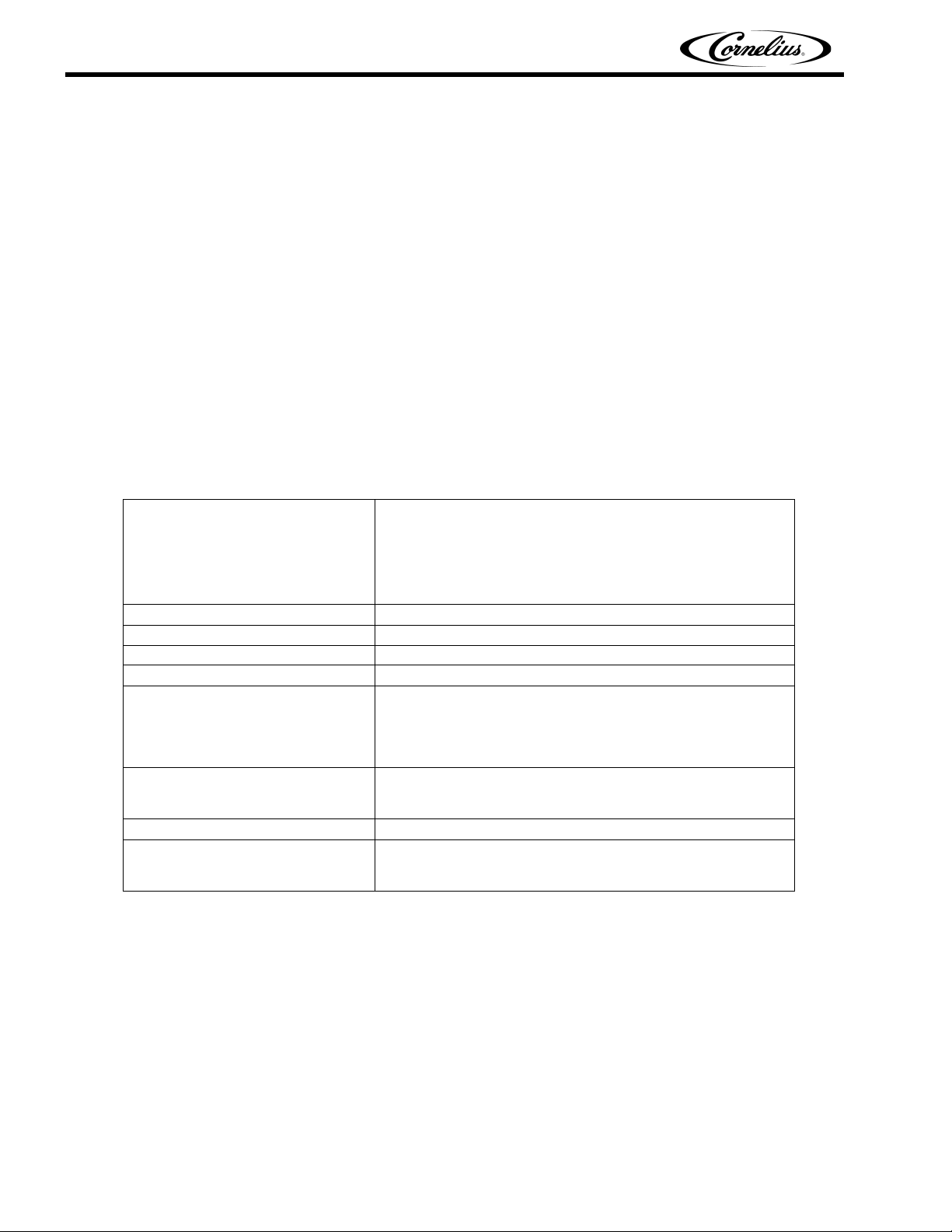
SPECIFICATION
Model Descriptions IDC 255
Unit Weight 368 Pounds
Ice Storage 255 Pounds
Maximum Number of Faucets 10
Built in Cold Plate Yes
Electrical 120/1/60
Dimensions Width 29.90 inch (.76 m)
CO2 Operating Pressure 75-psig (max)
Water 100 psi (7 bar) maximum static pressure.
B=Beverage
C=Coldplate
H=Internal Carb
P=Progate
Z=No Drip Tray
9.3 Amps of Total Unit Draw
OR
220/1/50
4.7 Amps of Total Unit Draw
Height 39.75 inch (1.0 m)
Depth 36.90 inch (.94 m)
40 psi (2.8 bar) minimum dynamic pressure.
3/8” minimum water line recommended.
Publication Number: 621057419INS - 2 - © 2006, IMI Cornelius Inc.
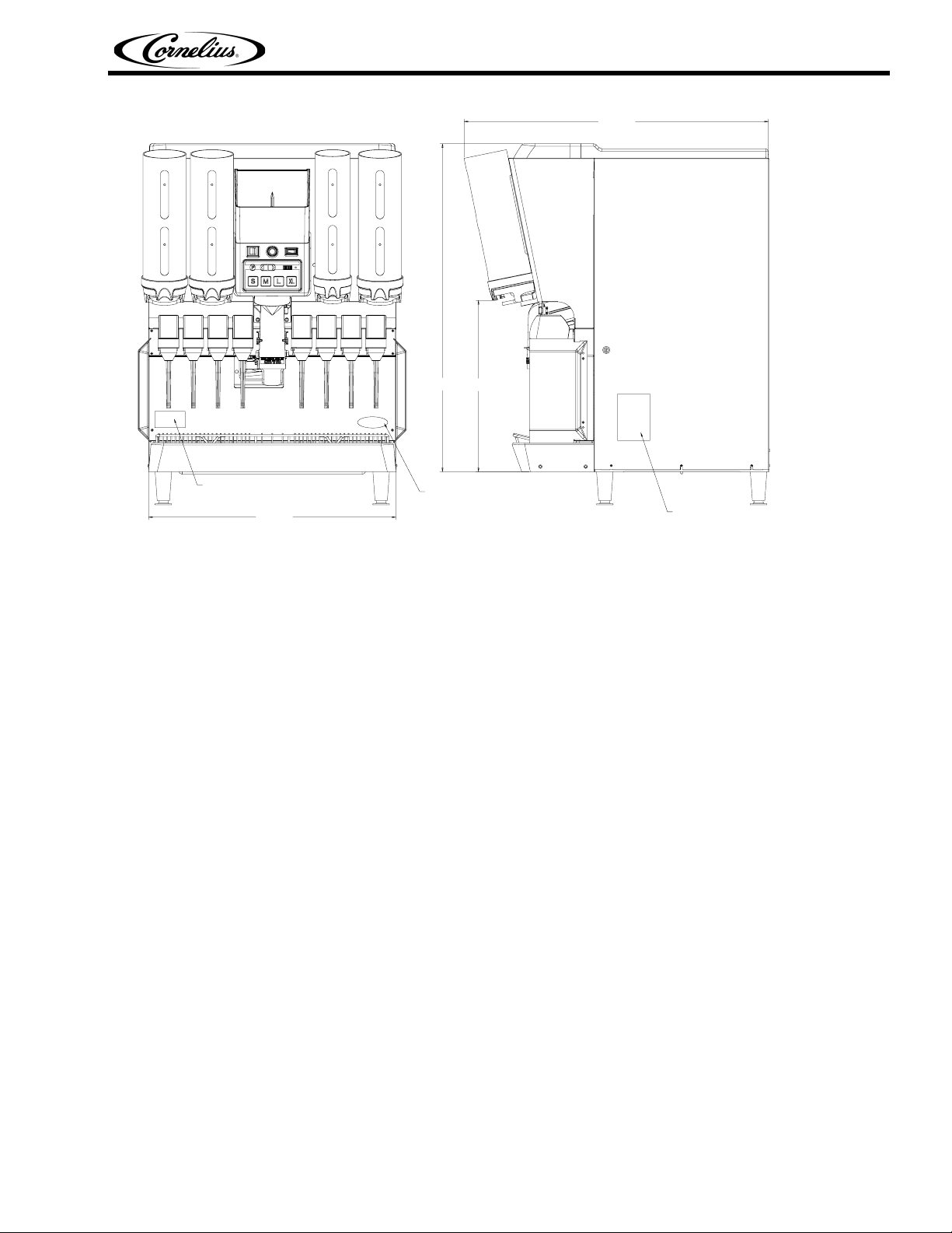
39.750
IDC 255 Progate Drive Thru Installation Manual
36.901
20.756
PCX
OUT OF RATIO
LABEL
30.000
Electrical Connections: 6 ft long power cord with 3-prong plug attached to dispenser.
Power Requirements: 9.3 amps at 120 volts dedicated power supply.
Water Supply Requirements: 100 psi (7 bar) maximum static pressure 40 psi (28 bar) minimum
dynamic pressure. 3/8” minimum water line recommended.
CO2 Requirements: 100 psi max to unit regulated to 35 psi (2.4 bar) to Progate 2 ice gate system, 75
psi (5.2 bar) carbonator.
Progate 2 Features
Progate Portion Ice Control Features
• 4 Programmable ice dispense sizes
• Automatic/Manual Ice Dispense Modes
• Unit Power On/Off Switch
• Programmable Agitation Time
Lid Dispenser
• 4 lid dispenser locations on the unit
• 3 Separate removable lid dispensers for small/medium, large, and extra large lids
CORNELIUS
LOGO
FIGURE 1
UNIT
SERIAL NUMBER
Straw Holder
• Holds up to 140 regular sleeved straws
© 2006, IMI Cornelius Inc. - 3 - Publication Number: 621057419INS
IDC 255 Progate Drive Thru Installation Manual
INSTALLATION
MOUNTING AND PLACEMENT
IMPORTANT: TO THE INSTALLER.
It is the responsibility of the Installer to ensure that the water supply to the dispensing equipment
is provided with protection against backflow by an air gap as defined in ANSI/ASME A112. 1.2–
1979; or an approved vacuum breaker or other such method as proved effective by test.
Water pipe connections and fixtures directly connected to a potable water supply shall be sized, installed,
and maintained according to Federal, State, and Local laws.
1. Locate the dispenser indoors on a level counter top.
A. LEG OPTION
Unpack the four (4) legs and install them into the threaded holes provided in the bottom of the
unit. The installer must provide flexibility in the product and utility supply to permit shifting the
position of the dispenser sufficiently to clean the area beneath it.
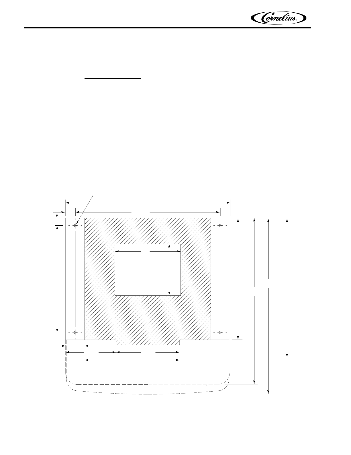
COUNTER MOUNTING
The ice drink dispenser must be sealed to the counter. The template drawing indicates where openings
can be cut in the counter. Locate the desired position for the dispenser, then mark the outline dimensions
on the counter using the template drawings. Cut openings in counter.
ZStyle
15/16
18 5/8
31/2
91/2
7/16 DIA.
23
30
26 3/81 13/16
12
9
21 1/4
11
30
31 1/2
23 1/16
REMOVABLE SINK
RECOMMENDED COUNTER OPENING SIZE
9 X 12 FOR UTILITIES AND BEVERAGE
TUBING. OPENING CAN BE LOCATED
ANYWHERE WITHIN SHADED AREA.
FIGURE 2
Publication Number: 621057419INS - 4 - © 2006, IMI Cornelius Inc.
IDC 255 Progate Drive Thru Installation Manual
Apply a continuous bead of NSF International (NSF) silastic sealant (Dow 732 or equal) approximately
1/4-inch inside of the unit outline dimensions and around all openings. Then, position the unit on the
counter within the outline dimensions. All excess sealant must be wiped away immediately.
2. The beverage tubes, drain tube and power cord are routed through the large opening in the bottom
of the unit. See the MOUNTING TEMPLATE for locating the required clearance opening in the
counter for these utility lines.
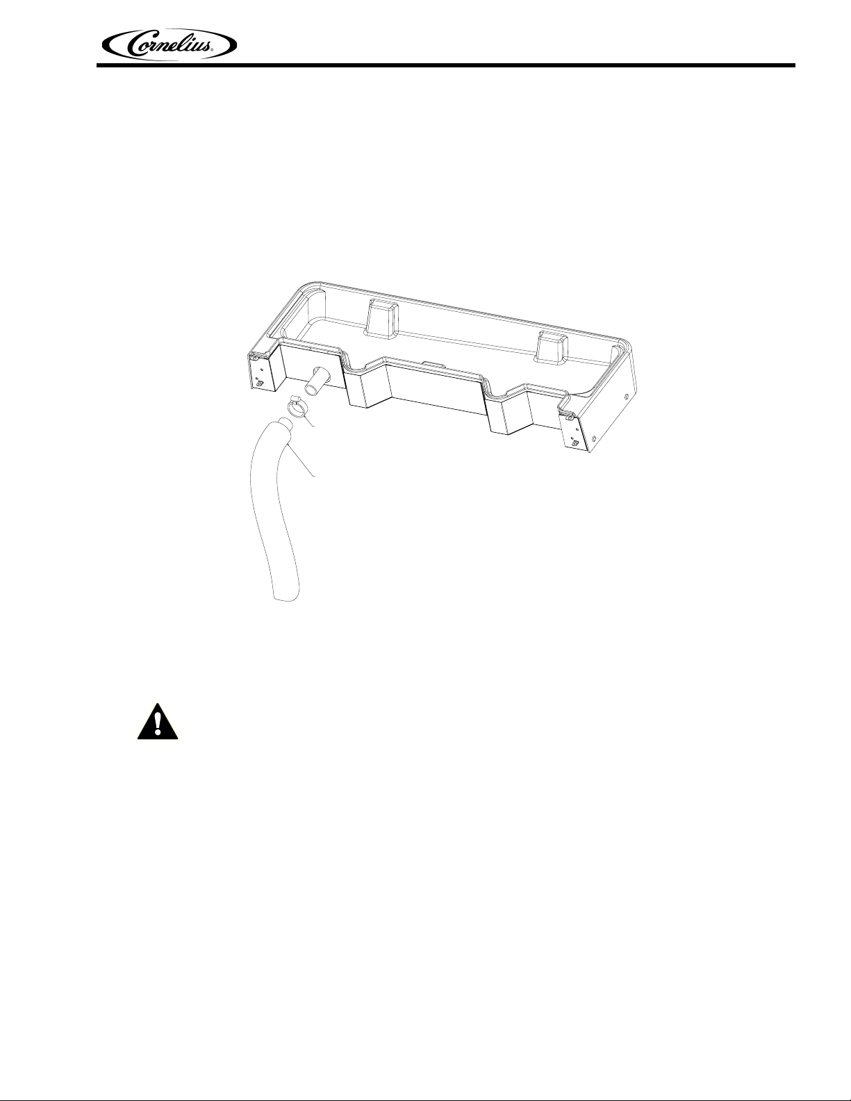
DRIP TRAY DRAIN ASSEMBLY: Route the drain tube to an open drain with the end of the tube above
the “flood” level of the drain. Use the tubing, fittings, clamps, and insulation provided with the Dispenser
to assemble the drain. The completed drain line
must pitch continuously downward and contain no
“traps” or improper drainage will result.
HOSE CLAMP
DRAIN LINE
1" I.D. PLASTIC TUBING
(6') WITH INSULATION
FIGURE 3
NOTE: IMI Cornelius Inc. recommends that a water shutoff valve and water filter be installed in
the plain water inlet supply line. A Cornelius Water Filter (P/N 313860000) and QUICK
DISCONNECT SET (P/N 313867000) are recommended.
CAUTION: Check the minimum flow rate and the maximum pressure of the plain water inlet supply
line. MINIMUM FLOW RATE MUST BE AT LEAST 125-GALLONS PER HOUR. If flow rate is less
than 125-gallons per hour, starving of the carbonator water pump will occur. Starving will overheat
the carbonator’s water pump, causing the safety thermostat on the pump outlet to stop the water
pump motor. Overheating could occur if the plain water supply line flow rate drops below 125gallons per hour. INCOMING PLAIN WATER INLET SUPPLY LINE WATER TO PUMP PRESSURE
MUST REMAIN A MINIMUM OF 10 psi BELOW THE CARBONATED CO
PRESSURE. (Example: Carbonator CO
operating pressure is 75 psi and the maximum water
2
pressure can be no more than 65 psi, etc.). Static water pressure higher then the static CO
OPERATING
2
2
pressure can cause carbonator flooding, malfunction, and leakage through the carbonator relief
valve. If water is exceeding maximum pressure specifications, a Water Pressure Regulator Kit must
be installed in the plain water inlet supply line.
3. Cut power to the carbonator by turning off its power switch, the switch is located on the junction box
of the pump and motor assembly. Locate the carbonator pump assembly and connect to power cord
from the Ice/Drink Unit to the pump. The cord is connected to the unit’s electrical box and has an
electrical connector on the end that plugs into a receptacle in the junction box at the carbonator
pump assembly. Connect inlet water to pump and pump outlet to Ice/Drink Unit using 3/8-inch foodgrade tubing.
© 2006, IMI Cornelius Inc. - 5 - Publication Number: 621057419INS

IDC 255 Progate Drive Thru Installation Manual
4. Connect the beverage system product tubes as indicated in applicable Flow Diagram in this manual
or on the back of the splash panel. This work should be done by a qualified service person.
NOTE: See applicable Flow Diagram or Decal on the lower front of the unit for the location of
syrup and water connections.
5. Clean the hopper interior.
6. Connect the unit power cord to a 120 volt, 60 cycle, 3–wire grounded receptacle. For 220-240 Volt
International Units, a 3-wire power cord is provided. An adapter plug for the particular country will
need to be provided by the Installer.
ADJUST CARBONATOR CO2 REGULATOR AND TURN WATER INLET SUPPLY
LINE ON
1. Open (counterclockwise) CO2 cylinder valve slightly to allow lines to slowly fill with gas, then open
the valve fully to back-seat the valve. (Back-seating the valve prevents leakage around the valve
shaft).
2. The carbonator CO
3. Open one of the post-mix dispensing valves to exhaust trapped air inside the carbonator tank.
4. Open the water inlet supply line shutoff valve.
regulator is fixed at a nominal 75 psi.
2
Publication Number: 621057419INS - 6 - © 2006, IMI Cornelius Inc.
 Loading...