

IMI Cornelius, Inc. COR20RRTM, COR22RRTM, COR40RRTMD, COR48RRTMD, COR74RRTMT Service Manual
Page 1
®
REACH-IN REFRIGERATORS
COR20RRTM, COR22RRTM, COR40RRTMD,
COR48RRTMD, COR74RRTMT
Service Manual
Release Date: June 16, 2004
Publication Number: 630460252SER
Revision Date: NA
Revision: A
Visit the IMI Cornelius web site at www.cornelius.com
for all your Literature needs.
Page 2
SERVICE MANUAL
The products, technical information, and instructions contained in this manual are subject
to change without notice. These instructions are not intended to cover all details or variations of the equipment, nor to provide for every possible contingency in the installation,
operation or maintenance of this equipment. This manual assumes that the person(s)
working on the equipment have been trained and are skilled in working with electrical,
plumbing, pneumatic, and mechanical equipment. It is assumed that appropriate safety
precautions are taken and that all local safety and construction requirements are being
met, in addition to the information contained in this manual.
To inquire about current revisions of this and other documentation or for assistance with
any Cornelius product contact:
www.cornelius.com
800-238-3600
Trademarks and copyrights:
Aurora, Cornelius, Decade, Hydro Boost, Sitco, Spirit, UF-1, Vanguard, Venture, Olympus,
and Vista are registered trademarks of IMI Cornelius Inc.
Optifill trademark is pending.
This document contains proprietary information and it may not be
reproduced in any way without permission from Cornelius.
Printed in U.S.A.
Copyright © 2004, All Rights Reserved, IMI Cornelius, Inc.
Page 3
Reach-In Refrigerator Service Manual
TABLE OF CONTENTS
Features of the Unit . . . . . . . . . . . . . . . . . . . . . . . . . . . . . . . . . . . . . . . . . . . . . . . . . . 1
Cleaning and Preventive Maintenance . . . . . . . . . . . . . . . . . . . . . . . . . . . . . . . . . . . 2
How Your Cabinet Operates . . . . . . . . . . . . . . . . . . . . . . . . . . . . . . . . . . . . . . . . . . . 3
Defrost water flow . . . . . . . . . . . . . . . . . . . . . . . . . . . . . . . . . . . . . . . . . . . . . . . . 3
Warning light and thermometer . . . . . . . . . . . . . . . . . . . . . . . . . . . . . . . . . . . . . . 3
Temperature control . . . . . . . . . . . . . . . . . . . . . . . . . . . . . . . . . . . . . . . . . . . . . . 4
Automatic defrosting . . . . . . . . . . . . . . . . . . . . . . . . . . . . . . . . . . . . . . . . . . . . . . 4
Service Procedures . . . . . . . . . . . . . . . . . . . . . . . . . . . . . . . . . . . . . . . . . . . . . . . . . . 4
Light switches . . . . . . . . . . . . . . . . . . . . . . . . . . . . . . . . . . . . . . . . . . . . . . . . . . . 4
Lights . . . . . . . . . . . . . . . . . . . . . . . . . . . . . . . . . . . . . . . . . . . . . . . . . . . . . . . . . . 5
Temperature controls . . . . . . . . . . . . . . . . . . . . . . . . . . . . . . . . . . . . . . . . . . . . . 5
Time clocks . . . . . . . . . . . . . . . . . . . . . . . . . . . . . . . . . . . . . . . . . . . . . . . . . . . . . 6
Blower fan assembly . . . . . . . . . . . . . . . . . . . . . . . . . . . . . . . . . . . . . . . . . . . . . . 8
Defrost heater . . . . . . . . . . . . . . . . . . . . . . . . . . . . . . . . . . . . . . . . . . . . . . . . . . . 8
Condensing unit . . . . . . . . . . . . . . . . . . . . . . . . . . . . . . . . . . . . . . . . . . . . . . . . . 9
Wiring Diagrams . . . . . . . . . . . . . . . . . . . . . . . . . . . . . . . . . . . . . . . . . . . . . . . . . . . 10
COR20RRTM . . . . . . . . . . . . . . . . . . . . . . . . . . . . . . . . . . . . . . . . . . . . . . . . . . 10
COR22RRTM . . . . . . . . . . . . . . . . . . . . . . . . . . . . . . . . . . . . . . . . . . . . . . . . . . 11
COR40RRTMD . . . . . . . . . . . . . . . . . . . . . . . . . . . . . . . . . . . . . . . . . . . . . . . . . 12
COR48RRTMD . . . . . . . . . . . . . . . . . . . . . . . . . . . . . . . . . . . . . . . . . . . . . . . . . 13
COR74RRTMT . . . . . . . . . . . . . . . . . . . . . . . . . . . . . . . . . . . . . . . . . . . . . . . . . 14
Troubleshooting . . . . . . . . . . . . . . . . . . . . . . . . . . . . . . . . . . . . . . . . . . . . . . . . . . . 15
Possible causes and solutions . . . . . . . . . . . . . . . . . . . . . . . . . . . . . . . . . . . . . 15
© 2004, IMI Cornelius Inc. - i - Publication Number: 630460272SER
Page 4

Reach-In Refrigerator Service Manual
Publication Number: 630460272SER - ii - © 2004, IMI Cornelius Inc.
Page 5
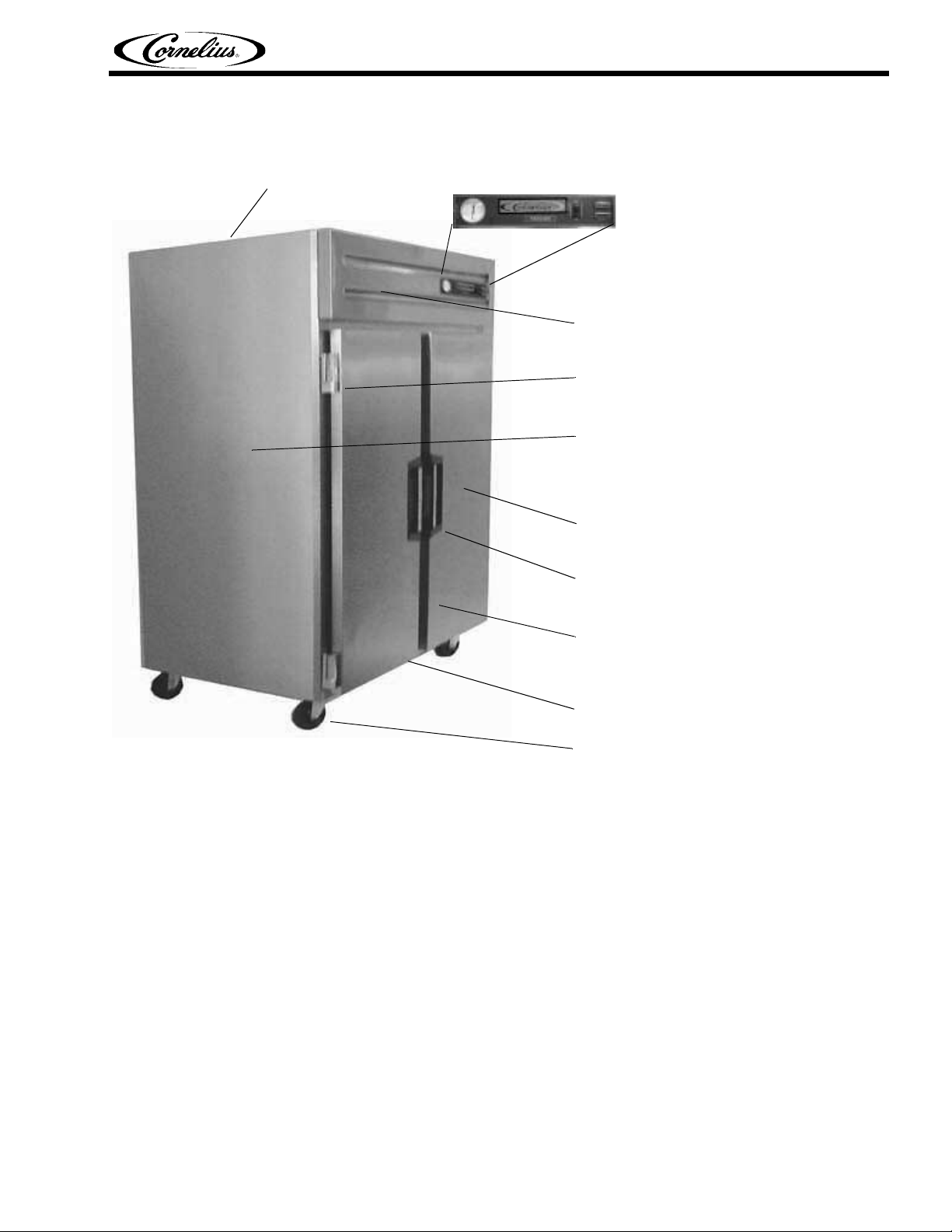
FEATURES OF THE UNIT
Heavy duty condensing
unit located on top for
easy-access maintenance.
Reach-In Refrigerator Service Manual
Control panel with
temperature display, door ajar
light, power indicator,
condensate switch
U.L. compliant electrical components
Heavy duty hinges with self-closing mechanism
Strong body with 2 1/2” thick walls injected with
CFC-free polyurethane. Stainless steel front
and exterior sides.
COR48RRTMD
Heavy duty shelves
Recessed handles with cylinder lock
Solid doors save energy by preventing warm air
from reaching your products.
Forced air evaporator for quick temperature pull
down
6” swivel casters
FIGURE 1
© 2004, IMI Cornelius Inc. - 1 - Publication Number: 630460272S ER
Page 6
Reach-In Refrigerator Service Manual
CLEANING AND PREVENTIVE MAINTENANCE
Weekly or sooner, as required:
1. Disconnect the power source before cleaning. Remove all products and place in a proper cooler.
2. Clean the interior and exterior with a mild soap or detergent solution and then rinse with a warm
baking soda solution (one cup of baking soda to one gallon of warm water). Dry the interior
completely before replacing products.
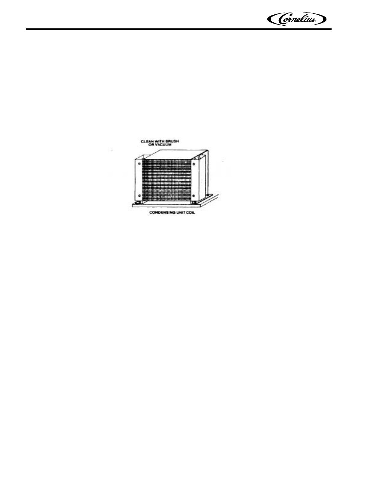
3. Clean the condenser unit periodically by vacuuming the unit compartment, especially the
condenser unit coil (it looks like a small auto radiator). If the condenser coil has accumulated dirt
and grease (possible in heavy traffic areas or a kitchen), use a strong cleaning solution. If you find
any oil in the condensing unit compartment, call a qualified service person immediately.
FIGURE 2
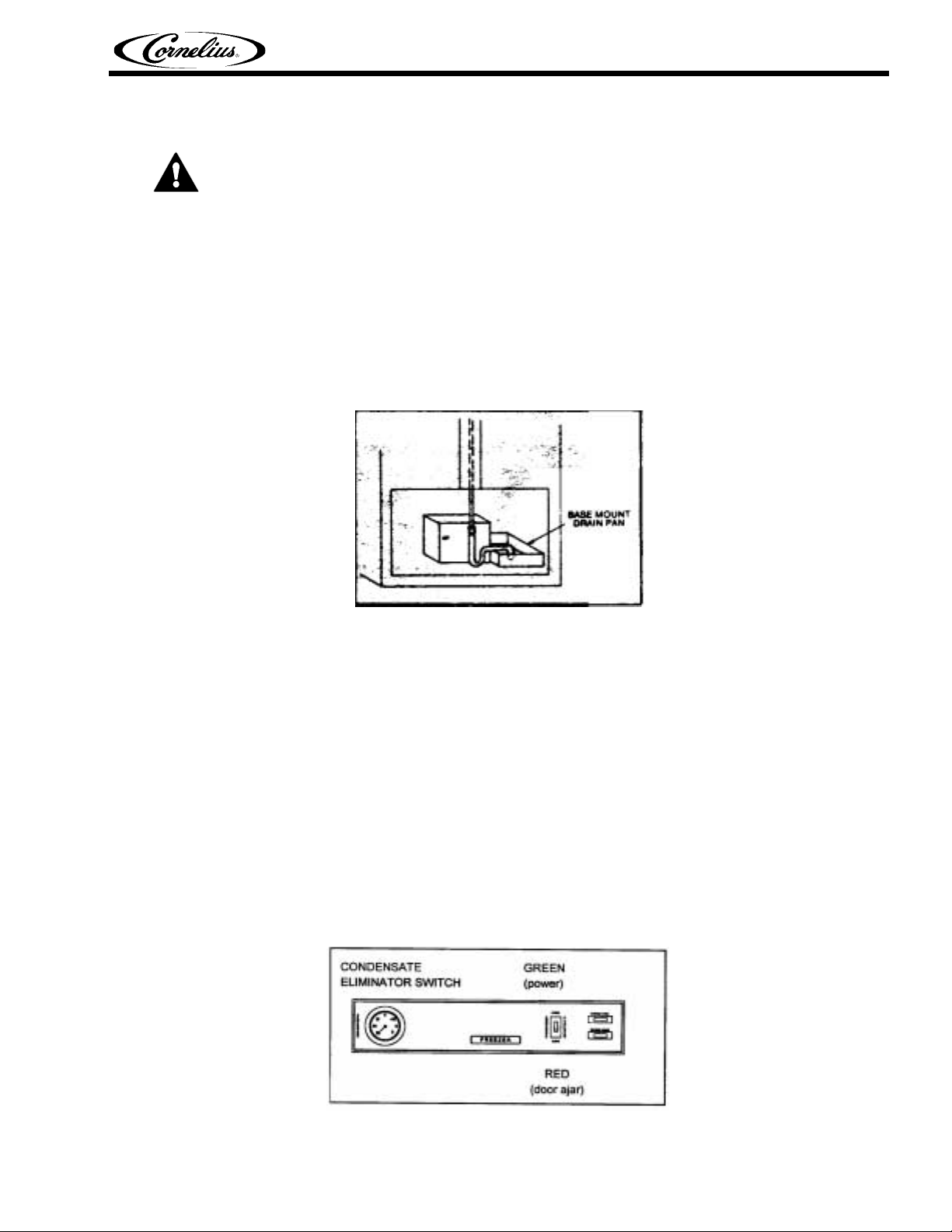
4. Empty out and clean drain pan located next to the condensing unit as required. Check regularly for
excessive water accumulation.
5. Plug in the cabinet and wait until the proper temperature is achieved before reloading the cabinet
with product.
Publication Number: 630460272SER - 2 - © 2004, IMI Cornelius Inc.
Page 7
HOW YOUR CABINET OPERATES
CAUTION - Make sure the power supply is turned off before making any electrical repairs.
Defrost water flow
Your new cabinet is completely self-defrosting. The frost that collects on the concealed coils is
automatically removed at predetermined intervals. The defrost water on top-mounted condensing units
flows into a thermostatically controlled electric vaporizer where it is dissipated into the atmosphere. All
defrost evaporator systems are designed for normal conditions; however, under some conditions, where
practical and convenient, a drain line to a floor drain may be preferable to the vaporizer. On basemounted condensing units, the defrost water flows into the unit compartment and is vaporized by the heat
from the hot gas line.
Reach-In Refrigerator Service Manual
Warning light and thermometer
A fan circulates the cold air from the coil throughout the storage area. This provides uniform
termperatures and more rapid recovery after door openings. The number of door openings and the length
of time the door is left open should be kept to a minimum to reduce the operating cost and maintain the
most efficient operation. The temperature in the cabinet will rise very rapidly whenever the doors are
opened; however, the product temperature is not greatly affected.
Some top-mounted cabinets have a thermometer and two small lights located at the right end of the front
motor cover grill, directly over the door. One light is green and is always lit when there is power to the
cabinet. One light is red and should only be lit when the temperature is above the safe zone. It is
controlled by a bi-metallic disk type switch.
The red light will be on at start up until the temperature comes down to normal. When warm product is
put in or the doors are held open for a time, the red light may come on but it will go out again as soon as
the temperature has recovered. When the doors are closed again, the recovery is very rapid unless a
large quantity of warm product is put in at one time.
FIGURE 3
FIGURE 4
© 2004, IMI Cornelius Inc. - 3 - Publication Number: 630460272S ER
Page 8

Reach-In Refrigerator Service Manual
Temperature control
If the condensing unit does not run after the power cord is plugged in, check that the temperature control
is in the “on” position. This can be done with an ordinary screwdriver. After the system has operated for
several hours, the temperature control may be adjusted to suit your needs. Turn it clockwise to make it
colder and counterclockwise to make it warmer. Do not make more than 1/4 turn at one time; then allow it
to operate for several hours before making any further adjustment. Once it is set there should be no need
to change it.
After the cabinet has been used for a while, if you should notice any great change in termperature, do not
attempt to compensate for it by turning the control. It is much more likely that there is some other problem
and a qualified refrigeration service person should be called.
Automatic defrosting
Normally, when the cabinet storage area temperature is kept at a range of 36oF to 42oF, all refrigerators
will defrost the coil during the off cycle (when the compressor is not running). Under some conditions,
such as heavy product load or a lot of door openings in a high ambient temperature or excessive relative
humidity, it may be advisable to install a time clock which will automatically shut the condensing unit off
for an hour or two each night to be sure the coil is completely cleared of frost. It should be connected so
the blower fan is left on to speed up the defrosting process. A qualified service person should be
consulted before attempting to make these additions.
SERVICE PROCEDURES
FIGURE 5
CAUTION - Make sure the power supply is turned off before making any electrical repairs.
If any electrical problems arise, a wiring diagram is included with each cabinet to aid in tracing the source
of trouble and making the necessary repairs.
Light switches
Each hinged solid door has a switch which will turn on the interior light whenever the door is opened. In
most cases the switch may be examined or exchanged without removing the mounting bracket. Place a
knife blade or similar tool behind the switch flange and pry it out. To replace the switch, disconnect the
Publication Number: 630460272SER - 4 - © 2004, IMI Cornelius Inc.
Page 9

Reach-In Refrigerator Service Manual
leads from the terminals and attach them to the new switch and snap it back in place. Make sure there
are no breaks or bare wires to cause a short before putting the switch back.
FIGURE 6
Lights
The incandescent light bulb can be replaced by any 40 watt appliance bulb.
Temperature controls
CAUTION - Make sure the power supply is turned off before making any electrical repairs.
To replace the temperature control:
1. Remove the two mounting screws.
© 2004, IMI Cornelius Inc. - 5 - Publication Number: 630460272S ER
Page 10

Reach-In Refrigerator Service Manual
2. Pull the feeler bulb from the well which is usually located on the coil or header and pull the lead
wires off the control terminals.
If the temperature control is within the first year warranty and is to be returned for credit, be sure to
coil the tubing neatly and do not kink it or damage the control in any way. No credit can be issued for
any parts that arrive in a damaged condition.
3. Replace the control with an exact factory replacement or one equal to the original specifications. Be
sure the feeler bulb is in the proper well and tight. Do not allow the tubing connecting the feeler bulb
to the body of the control to touch the coil U bends.
Time clocks
In the cabinets which have bottom-mounted condensing units, the time clock will be located along the
side of the unit. It will be readily visible when the motor cover is removed. The timer is set at the factory
for two defrost periods with a fail safe of 40 minutes for both single and multiple door cabinets. (For SAV
models the timer is set at the factory for four (4) defrost periods of 30 minutes.) Tests have shown that the
factory setting is satisfactory for most applications. However, changes can be made after a sufficient trial
period if necessary.
The fail safe is controlled by the small copper pointer on the inner dial. To reset the timer, grasp the
knurled knob and turn it counterclockwise until the pointer is at the correct time. As soon as the power is
turned on, if the temperature control is in the “on” position, the time clock and condensing unit will start.
FIGURE 7
Publication Number: 630460272SER - 6 - © 2004, IMI Cornelius Inc.
Page 11

Reach-In Refrigerator Service Manual
FIGURE 8
When the coil temperature reaches the proper temperature, the fan(s) will automatically start and
continue to run until it comes to the defrost cycle. The fan(s) may turn off if the doors are left open too
long during a loading period and the coil becomes warm. Do not call for service until the freezer is given
enough time to come down to the proper temperature. After the unit is put into operation, the fan(s) will
continue to operate until the storage area reaches a proper temperature (recommended average 38
The red pilot on the front of the top grill should turn off after about an hour of operation or whenever the
sensing element reaches the prescribed temperature. Under some conditions the red warning light may
go on at the end of the defrost cycle. However, after the defrost cycle is ended, the temperature should
recover in a reasonable length of time and the red light will go out. The defrost periods are set at the
factory for 6 a.m. and 6 p.m. and may be changed if needed.
o
F).
When the pin on the outer dial of the time clock is opposite the pointer, the defrost cycle will start. The
condensing unit and the blower fan shut off and the defrost heaters turn on. The heaters are located on
the coil. As soon as the coil has reached approximately 50
limit and fan delay switch will trip the timer solenoid and end the defrost cycle to put the system back into
the refrigeration cycle. The blower fan will remain off until the coil cools down to 20
solenoid should fail to terminate the defrost cycle, the inner fail safe dial will take over and terminate the
defrost cycle when the prescribed time is up. The length of the defrost cycle will vary depending on the
type of product stored in the cabinet, the number of door openings, and the atmospheric conditions. The
defrost cycle will usually take longer in the summer than in the winter. Before you make changes to the
length of the fail safe or the number of defrost periods, a competent service engineer should make a
complete study of all the contributing factors.
o
F and the coil is clear, the combination defrost
o
F. If the limit switch or
© 2004, IMI Cornelius Inc. - 7 - Publication Number: 630460272S ER
Page 12

Reach-In Refrigerator Service Manual
Blower fan assembly
To change the fan blade, remove the speed nut from the threaded shaft. If the fan motor must be
changed:
1. Remove the fan blade and lay it carefully aside. Be careful not to bend or damage the blade or it will
become out of balance.
2. Remove the four machine screws around the perimeter of the hole in the baffle. These hold the
motor mounting bracket in place. The small rubber washers that eliminate vibration should be saved
for reassembly.
3. Drop the motor and bracket through the hold.
4. Remove the three machine screws holding the motor to the mounting bracket and disconnect the
wire leads.
5. Install the new fan motor and reinstall the fan blade.
Defrost heater
To change the defrost heater element:
1. Remove the baffle from under the coil. This is the part that catches the condensate water and
funnels it down the drain. It also directs the flow of air through the coil and down the air ducts. To
remove the baffle, take out the screws and let it down far enough to get to the defrost element.
2. Use a pair of side cutters or diagonal pliers to snip off all of the copper wires holding the heater
element to the coil.
3. Disconnect the element from the cabinet leads.
FIGURE 9
FIGURE 10
Publication Number: 630460272SER - 8 - © 2004, IMI Cornelius Inc.
Page 13

4. Install a new heater element. Be sure to use similar copper wire to install the new element tightly
against the coil. Note that there is a bend in the heater element along the center rear. This must
make good contact with the drain pan or baffle at the drain opening in order to work properly. If it
does not make good contact, the drain line will freeze up and the defrost water will overflow into the
food compartment during the defrost cycle.
Condensing unit
The condensing unit consists of the following parts:
• Compressor
• Condenser fan motor assembly
• Condenser
• Relay
• Starting capacitor (running capacitor on some models)
• Service valves. Most units have high and low side service valves, but in some instances there may be
only a low side service valve.
Some compressors have the mechanism mounted on springs inside the housing (referred to as internal
mounts) and others have the entire compressor body mounted on springs and rubber bushings (referred
to as external mounts) to absorb the vibration. In the latter case bolts run up through the springs and are
secured with a retainer nut. During shipping the nuts on these bolts are tightened to prevent the
compressor from moving and damaging itself or other parts. Before the cabinet is placed in operation,
these nuts must be loosened enough to allow the compressor to float freely on the springs so that
vibration will be absorbed by the springs.
Reach-In Refrigerator Service Manual
Problems with the refrigeration system are usually due to failure of one of the components in the
condensing unit area. The service person should install a set of gages on the service valves to determine
the operating pressures. Compare these pressures to the specifications to determine the cause and
solution.
If there is an electrical problem, the service person should use a volt/amp meter, a watt meter, and a
continuity tester. An ohm meter can be used as a continuity tester.
A common refrigeration failure is a leak of some or all of the refrigerant. Because the leak can be very
small it can be very difficult to find. It usually develops on the high side of the system and only leaks when
the compressor is running. The condenser fan carries the refrigerant away making the leak difficult to
detect. If a leak detector does not find the leak, put a block of wood or a wad of rags against the fan blade
to keep it from turning while the compressor is running. This will cause the pressure to build up and make
the leak easier to find. This will not harm the fan motor or system if the fan blade is only stopped for a few
minutes.
The pick up hose of the torch should be passed back and forth over all tubing joints and over the entire
condenser very carefully. After the leak is found, repair it if possible. If it cannot be repaired, replace the
leaking part.
Whenever a leak has been located and repaired, the entire charge should be removed and a triple
evacuation procedure must be followed to be sure that all contaminants are removed. A good dryer of
proper size should be installed in the liquid line and a new charge of refrigerant put back in allowing extra
to compensate for the dryer.
After the cabinet has run for several hours, it should be rechecked to be sure the gas charge is correct
and the system is balanced.
© 2004, IMI Cornelius Inc. - 9 - Publication Number: 630460272S ER
Page 14

Reach-In Refrigerator Service Manual
WIRING DIAGRAMS
COR20RRTM
TEMP. CONTROL
RED
BLACK
COND. UNIT
FAN MOTOR
BLACK
WHITE
WHITE
RED
WHITE
BLACK
BLACK
PERIMETER HEATER
BLACK
PUSH
BUTTOM
BLACK
JUNCTION
BOX
BLACK
GREEN
WHITE
WHITE
BLACK
RED
BLACK
WHITE
WHITE
WHITE
LIGHT
BULB
BLACK
SPEAR LINE
FIGURE 11
Publication Number: 630460272SER - 10 - © 2004, IMI Cornelius Inc.
Page 15

COR22RRTM
HEATERS - FASCIA
BLACK
WHITE
BLACK
WHITE
MULLION/CANOPY
CONNECTION
BBG
PUSH
BUTTOM
GREY
RED
BLACK
WHITE
LIGHT
BULB
Reach-In Refrigerator Service Manual
GREY
RED
BLACK
WHITE
W
GREEN
BLACK
WHITE
FEED
WHITE
BLACK
GREEN
SWITCH
ELECT. BOX
4 X 4
HEATER
SWITCH
POWER
DOOR
AJAR
GREEN
EVAP.
PAN
COND.
UNIT
WHITE
BLACK
GREEN
RED
WHITE
FAN MOTOR
WHITE
BLACK
FIGURE 12
BLACK
WHITE
BAFFLE
CONNECTION
RED
CONTROL
RED
BLACK
© 2004, IMI Cornelius Inc. - 11 - Publication Number: 630460272S ER
Page 16

Reach-In Refrigerator Service Manual
COR40RRTMD
TEMP. CONTROL
RED
BLACK
COND. UNIT
FAN MOTOR
BLACK
WHITE
WHITE
RED
WHITE
BLACK
BLACK
PERIMETER HEATER
BLACK
PUSH
BUTTOM
BLACK
JUNCTION
BOX
BLACK
GREEN
WHITE
WHITE
BLACK
RED
BLACK
WHITE
BLACK
BLACK
PUSH
BUTTOM
WHITE
WHITE
LIGHT
BULB
BLACK
SPEAR LINE
FIGURE 13
Publication Number: 630460272SER - 12 - © 2004, IMI Cornelius Inc.
Page 17

COR48RRTMD
BLACK
WHITE
BLACK
WHITE
Reach-In Refrigerator Service Manual
MULLION/CANOPY
CONNECTION
GREY GREY
RED
BLACK
WHITE
RED
BLACK
WHITE
HEATER
SWITCH
POWER
DOOR
AJAR
MULLION HEATERS
HEATERS - FASCIA
BLACK
WHITE
BLACK
WHITE
PUSH
BUTTOM
BGGW
LIGHT
BULB
PUSH
BUTTOM
BB
GREEN
BLACK
WHITE
ELECT. BOX
4 X 4
RED
CONTROL
RED
BLACK
EVAP.
PAN
COND.
UNIT
FEED
WHITE
BLACK
GREEN
WHITE
BLACK
GREEN
RED
WHITE
FAN MOTOR
WHITE
BLACK
SWITCH
BLACK
WHITE
BAFFLE
CONNECTION
GREEN
FIGURE 14
© 2004, IMI Cornelius Inc. - 13 - Publication Number: 630460272S ER
Page 18

Reach-In Refrigerator Service Manual
COR74RRTMT
MULLION/CANOPY
CONNECTION
BLACK
WHITE
BLACK
WHITE
GREY GREY
RED
BLACK
WHITE
RED
BLACK
WHITE
HEATER
SWITCH
POWER
DOOR
AJAR
MULLION HEATERS
HEATERS - FASCIA
MULLION HEATERS
BLACK
WHITE
BLACK
WHITE
PUSH
BUTTOM
BGGW
LIGHT
BULB
PUSH
BUTTOM
BB
BW
LIGHT
BULB
FEED
EVAP.
PAN
COND.
UNIT
GB
PUSH
BUTTOM
WHITE
BLACK
GREEN
WHITE
BLACK
GREEN
RED
WHITE
FAN MOTOR
FIGURE 15
WHITE
BLACK
BLACK
WHITE
SWITCH
RED
BLACK
WHITE
BAFFLE
CONNECTION
GREEN
ELECT. BOX
4 X 4
CONTROL
RED
BLACK
GREEN
Publication Number: 630460272SER - 14 - © 2004, IMI Cornelius Inc.
Page 19

TROUBLESHOOTING
Possible causes and solutions
PROBLEM POSSIBLE CAUSE SOLUTION
Reach-In Refrigerator Service Manual
COMPRESSOR WILL NOT
START
No voltage in the electrical
socket.
The electrical conductor or
wires may be cut.
Defective electrical
components such as:
thermostat, relay, thermal
protector, etc.
Thermostat in “off” position. Turn the thermostat’s knob to
Compressor motor has a
winding open or shorted.
Dirty condenser; lack of air
flow.
Low voltage. Use a voltage regulator if the
Compressor is stuck. Change the compressor.
Use a voltmeter to check the
voltage.
Use an ohmmeter to check for
continuity.
Replace defective components.
its maximum position and wait
to see if the compressor starts.
Measure the ohmic resistance
of the main and auxiliary
windings using an ohmmeter.
Compare them with the correct
values.
Clean condenser and allow for
air circulation.
voltage is lower than 103 volts.
THE TEMPERATURE IS TOO
COLD
Temperature control contacts
are open.
Time clock circuits are open. Determine the reason and
Incorrect wiring. Check the wiring diagram and
Thermostat knob is set at a
very cold position.
Thermostat does not
disconnect the condensing unit.
Thermostat capillary bulb is
loose or installed improperly.
Control contacts are stuck
closed.
Defective or incorrect
temperature control.
Repair or replace the contacts.
repair or replace.
correct.
Set the thermostat knob to a
warmer position and check if
the compressor stops
according to the thermostat’s
operating range.
Check the insulation of the
thermostat. If the problem
persists, change the
thermostat.
Correctly fasten the thermostat
capillary bulb.
File contacts. Change the
control. Check amperage load.
Determine correct control and
replace.
© 2004, IMI Cornelius Inc. - 15 - Publication Number: 630460272S ER
Page 20

Reach-In Refrigerator Service Manual
PROBLEM POSSIBLE CAUSE SOLUTION
THE TEMPERATURE IS NOT
COLD ENOUGH
Thermostat knob is set at a
very warm position.
Set the thermostat knob to a
colder position.
Condenser is dirty. Clean the condenser.
The refrigerator has been
placed at an inadequate
location.
The unit must not be near
stoves, walls that are exposed
to the sun, or places that lack
sufficient air flow.
Compressor is inefficient or
there is a high head pressure
If there is air in the system,
purge and recharge.
due to air in the system.
Iced up evaporator coil. Check temperature control,
refrigerant charge, and defrost
mechanism. Remove all ice
manually and start over.
Restriction in system. Locate exact point of restriction
and correct.
The refrigerator has been used
improperly.
The shelves must never be
covered with any type of plastic
or other material that will block
the circulation of cold air within
the refrigerator.
Too many door openings. Advise user to decrease if
Excessive heat load placed in
cabinet.
The refrigerator has been
overcharged with the
refrigerant gas.
The refrigerant gas is leaking. Find the location where the gas
The evaporator and/or
condenser fans aren’t working.
Low voltage. Use a voltage regulator if the
ELECTRICAL SHOCKS Wires or electrical components
are in direct contact with
metallic parts.
possible.
Advise user not to put in
products that are too hot.
Check to see if condensation or
ice crystals have formed on the
suction line. If so, charge with
the correct amount of gas.
is leaking in order to seal it or
replace the defective
component. Change the drier.
Perform a good vacuum and
recharge the unit.
Check the electrical
connections and make sure
that the fan blade isn’t stuck.
Replace the fan motor if it
doesn’t work.
voltage is lower than 103 volts.
Check for appropriate
insulation on the connections of
each electrical component.
Publication Number: 630460272SER - 16 - © 2004, IMI Cornelius Inc.
Page 21

Reach-In Refrigerator Service Manual
PROBLEM POSSIBLE CAUSE SOLUTION
NOISE The refrigerator is not properly
leveled.
The condenser is not fastened
correctly. Copper tubings are in
contact with metal.
The evaporator and/or
condenser fans are loose.
Compressor has an internal
noise.
EXTREME CONDENSATION
INSIDE THE REFRIGERATOR
Thermostat knob is set at a
very cold position.
The outside environment’s
relative humidity is very high
(over 75%).
Check if the noise goes away
after you level the refrigerator.
While the compressor is
working, check to see if metal
parts are in contact with one
another and/or if the screws
that fasten the condenser are
tightened.
Check if the fans are securely
fastened. Also, check if the fan
blades are loose, broken or
crooked. If so, change the
faulty blade.
If the noise persists after all
other measures have been
taken, it may be originating
from the compressor.
Set the thermostat knob to a
warmer position and check if
the compressor stops
according to the thermostat’s
operating range.
This type of occurrence is
caused by local climatic
conditions and not by the
refrigerated unit.
The refrigerator door won’t shut
completely.
The refrigerator has been
placed at an inadequate
location.
NO ILLUMINATION The light switch is in “off”
position.
False contact on the light
switch, the fluorescent tube, or
the ballast.
Light switch, ballast and/or
fluorescent tube are damaged.
Check the door and/or the
magnetic gasket. Adjust the
door hinges if needed; replace
the gasket if broken.
The unit must not be near
sources that produce too much
heat.
Press the light switch to the
“on” position.
Inspect all connections.
Replace the damaged
component.
© 2004, IMI Cornelius Inc. - 17 - Publication Number: 630460272S ER
Page 22

IMI Cornelius Inc.
www.cornelius.com
 Loading...