

Page 1
CAUTION - Only trained and certified electrical, plumbing and refrigeration technicians should
service this unit. ALL WIRING AND PLUMBING MUST CONFORM TO NATIONAL AND LOCAL
CODES.
INTRODUCTION
Bottom Mounted Reach-In Freezer Installation Manual
INSTALLATION MANUAL
Reach-In Freezers
COR23RFBM, COR49RFBM
This manual contains instructions for installation, operation, and general maintenance of your
commercial freezer. It also includes a Troubleshooting chart to diagnose problems along with corrective
actions.
CHECK FOR SHIPPING DAMAGE
Prior to leaving the factory, each cabinet is thoroughly inspected and performance tested up to 12 hours
to assure proper operating temperatures.
Check the crate thoroughly for signs of shipping damage. If external damage exists, internal
damage is also probable and uncrating should be done while the carrier’s representative is present. In
any case, the equipment should be uncrated as soon as possible, preferably within five (5) days.
The manufacturer is not responsible for in-transit damage and the consignee must file any required
damage claims directly with the carrier.
If damage is severe and obvious, write a brief description of the evidence on the carrier’s delivery receipt
and above the carrier representative’s signature.
If hidden damage(s) is found, contact the carrier immediately (save all crating materials) and file the
necessary freight claim with the carrier.
CHECK FOR ACCESSORIES
Upon receiving the equipment, check that the shelves are inside the freezer, including the four clips or
supports for each shelf.
Release Date: May 17, 2004 www.cornelius.com Revision: A
© 2004, IMI Cornelius Inc. - 1 - Publication Number: 630460283INS
Page 2
Bottom Mounted Reach-In Freezer Installation Manual
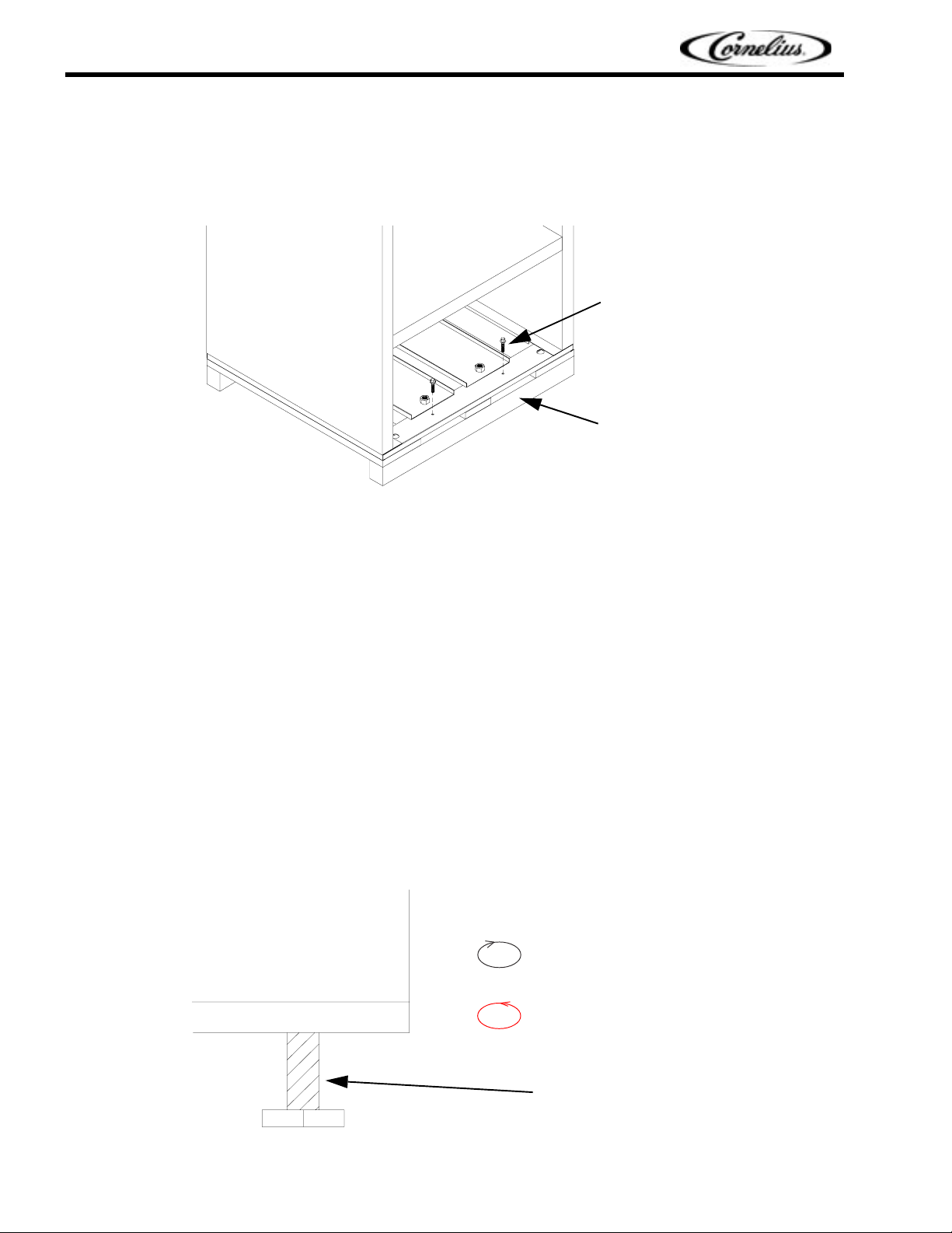
REMOVE THE CRATE AND SKID
Remove the crate carefully to prevent damage to the exterior surfaces of the cabinet. The cabinet is bolted to a
wooden skid with four hex-head bolts. After the skid is removed, always use a dolly to move the cabinet to
prevent damage to the cabinet bottom or the floor.
Bolt
Wooden skid
WHERE TO LOCATE THE CABINET
1. Place the unit on a surface that is solid enough to prevent vibration and strong enough to support
the combined weight of the cabinet and product load. Guideline: Estimate 35 pounds per cubic foot
of storage space.
2. Cabinets should never be placed in front of windows or glass doors in direct sunlight. If a cabinet is
located near a window or glass door, provide an adequate shade to block the sun’s rays.
3. Ambient temperature must be between 59° and 95° F. Low ambient temperatures below 50° are as
harmful as high ambient temperatures. Extreme temperatures will definitely affect the performance
of the cabinet.
4. Leveling legs are optional and are provided on some cabinets. Level the cabinet by using the
adjustable portion of the leveling legs as needed. Failure to properly level the cabinet could hinder
proper drainage and door operation. If the floor is extremely uneven, it may be necessary to shim
the corners with thin sheets of metal. (Shims may also be used when optional casters have been
included.)
FIGURE 1
Turn leg clockwise to lower
Turn leg counterclockwise to
raise
Leveling leg
FIGURE 2
Publication Number: 630460283INS - 2 - © 2004, IMI Cornelius Inc.
Page 3
Bottom Mounted Reach-In Freezer Installation Manual
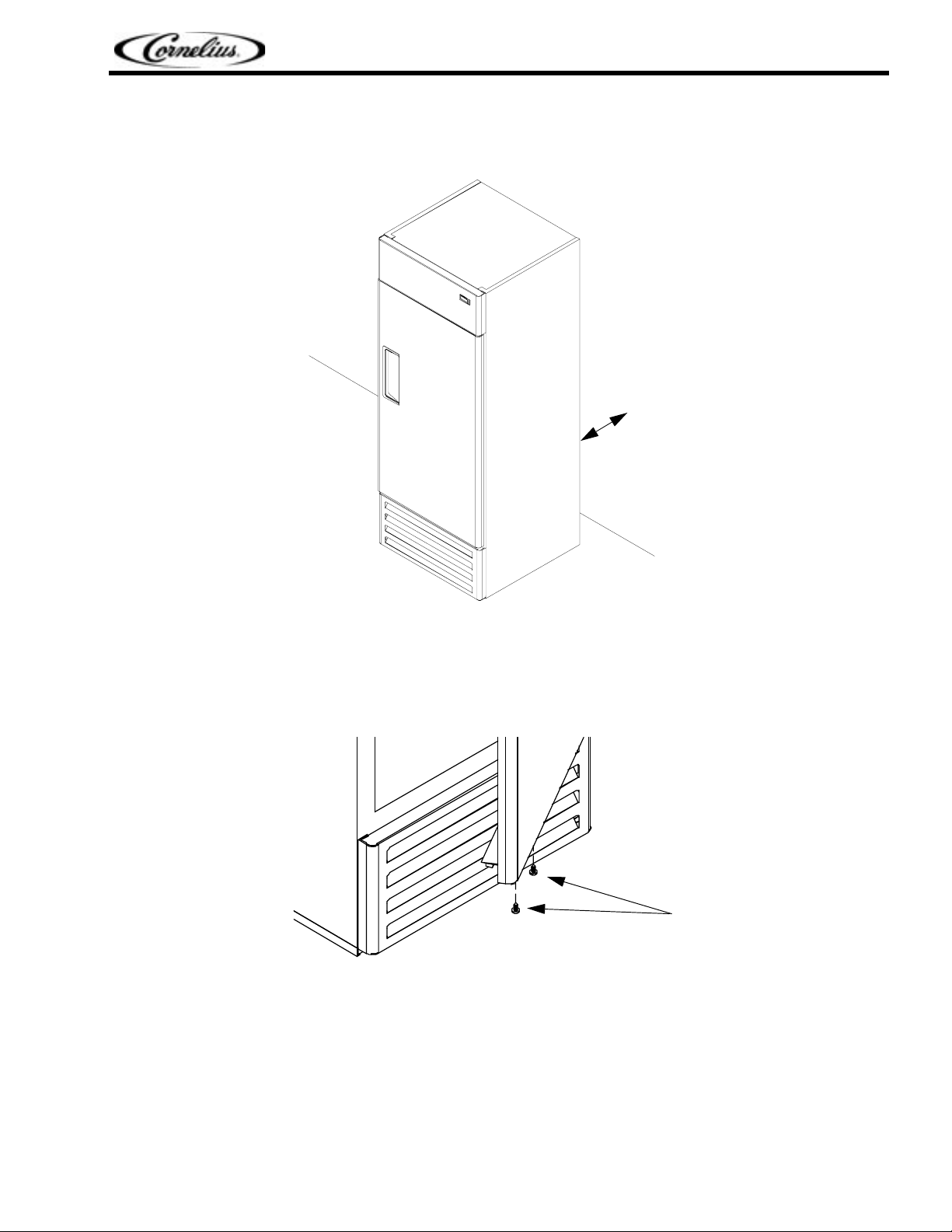
5. Clearance: Leave at least 8” between the back of the cabinet and the wall to provide adequate air
circulation of the unit compartment.
8”
FIGURE 3
REMOVE THE DOOR SUPPORT BRACKET
1. Open the door 30 degrees and loosen the screws.
FIGURE 4
Screws
© 2004, IMI Cornelius Inc. - 3 - Publication Number: 630460283INS
Page 4

Bottom Mounted Reach-In Freezer Installation Manual
2. Use a Phillips screwdriver to remove the door support bracket.
FIGURE 5
INSTALLATION
Measure all doorways and passages before moving the cabinet to its final location. To pass through low
door openings, first remove the shelves shipped inside the cabinet and lay one- and two-section upright
cases on end.
Door support bracket
CAUTION - Lay the cabinet on pads or thick blankets to avoid damage to the cabinet finish. After the
cabinet is set upright, check for oil leaks in the compressor compartment. If you find oil leaks, call a
qualified service person before operating the unit. If no oil leaks are found, wait 1/2 hour before operating
the unit.
If the doorway is too narrow to allow installation of the cabinet, follow these steps to remove the doors
and hinges on the unit:
1. Lift and remove the header sign (if applicable).
2. Use a wrench to loosen the hinge nut.
Publication Number: 630460283INS - 4 - © 2004, IMI Cornelius Inc.
Page 5

Bottom Mounted Reach-In Freezer Installation Manual
3. Relieve the spring tension by turning the spring hinge rod in the direction shown in the following
drawings:
Loosen hinge nut
Left bottom hinge
Spring hinge rod
Loosen hinge nut
Right bottom hinge
FIGURE 6
4. Unscrew the bottom hinge (the bottom hinge remains attached to the spring hinge rod).
5. Unscrew and remove the top hinge.
Top hinge
Spring hinge rod
Units with header sign Units without header sign
FIGURE 7
© 2004, IMI Cornelius Inc. - 5 - Publication Number: 630460283INS
Page 6

Bottom Mounted Reach-In Freezer Installation Manual
CONNECT THE CABINET TO A PROPER ELECTRICAL POWER SUPPLY
Each freezer requires a dedicated circuit to prevent malfunction of the compressor and the electrical
components. All models require a 115 V/60 Hz electrical supply on a 15 amp time-delay relay-type
breaker. Each unit should be connected to its own circuit in accordance with National Electric Codes and
local ordinances.
Check the line voltage to be sure the supply does not fluctuate more than 10%. Low line voltage can
shorten compressor life or contribute to service problems. If an extension cord is used, it must be a threeprong-grounding type (wire size 14 AWG or larger) and more than 15 feet long.
START UP THE CABINET
1. Shelves and shelf clips (4 clips per shelf) are packed inside the cabinet prior to shipment. After
selecting the appropriate spacing inside the cabinet, install the shelf clips by inserting the top of the
clip into the pilaster while pushing inwards and then downwards. Then insert the bottom of the clip
into the pilaster. Repeat until all the clips are in the desired locations. Place the shelves on the clips
and check that the shelves are level and all four corners are supported by the four shelf clips.
Pilaster
Clip
FIGURE 8
2. Plug in the electrical cord. Do not, under any circumstances, cut or remove the round grounding
prong from the power cord. Removal of the grounding prong invalidates the product warranty.
Grounding prong
FIGURE 9
Publication Number: 630460283INS - 6 - © 2004, IMI Cornelius Inc.
Page 7

ELECTRONIC THERMOSTAT
Your commercial freezer is manufactured with an electronic thermostat to control various functions of
your unit, such as the temperature, defrost cycles, fan operation, alarms, etc. The electronic thermostat
has been programmed at the factory and its keyboard was locked to prevent tampering.
Reading the LEDs
Each LED function is described in the following table:
LED Mode Function
Bottom Mounted Reach-In Freezer Installation Manual
FIGURE 10
ON Compressor enabled
To unlock the keyboard
Press and hold the keys for more than three seconds until the “PON” message is displayed.
The Set point parameter is the temperature at which the compressor cuts out.
To see the Set point
Push and immediately release the SET key and the display will show the Set point value.
Flashing
ON Defrost enabled
Flashing
ON Fans enabled
Flashing Fans delay after defrost in progress
ON A temperature alarm happened
• Programming Phase (flashing with )
• Anti-short cycle delay enabled
• Programming Phase (flashing with )
• Drip time in progress
To change the Set point
1. Push and hold the SET key for more than 2 seconds. The value of the Set point will be displayed
and the LED will start blinking.
2. Use the keys within 15 seconds of pressing the SET key to change the Set value.
3. To memorize a new Set point value, push the SET key again or wait 15 seconds. The compressor
Cut In temperature is the Set point value plus the Differential value. The Differential value is
programmed at the factory to protect the compressor from short cycling.
© 2004, IMI Cornelius Inc. - 7 - Publication Number: 630460283INS
Page 8

Bottom Mounted Reach-In Freezer Installation Manual
To lock the keyboard
Press and hold the keys for more than 3 seconds. The “POF” message will be displayed and the
keyboard will be locked. At this point it will only be possible to see the Set point or the Max or Min
temperature stored. If a key is pressed more than 3 seconds, the “POF” message is displayed.
Manual defrost
The electronic thermostat of the freezer controls the intervals between defrost cycle and the defrost
termination temperature. These values are set at the factory. A manual defrost cycle can be initiated if the
evaporator builds up too much ice.
To start a manual defrost, push and hold the DEF key for more than 2 seconds.
Publication Number: 630460283INS - 8 - © 2004, IMI Cornelius Inc.
Page 9

TROUBLESHOOTING
Possible causes and solutions
PROBLEM POSSIBLE CAUSE SOLUTION
Bottom Mounted Reach-In Freezer Installation Manual
COMPRESSOR WILL NOT
START, NO NOISE
WARM STORAGE
TEMPERATURES
COMPRESSOR RUNS
CONTINUOUSLY—PRODUCT
TOO COLD
Power disconnected Check service cord for proper
connection
Blown fuse or breaker Replace fuse or reset breaker
Defective or broken wiring Repair or replace wiring
Defective overload Replace
Defective relay Replace
Temperature control not set
properly
Not enough refrigerant Leak check. Change drier,
Cabinet location too warm Relocate cabinet
Too much refrigerant Change drier, evacuate, and
Low voltage, compressor
cycling on overload
Defective thermostat Replace
Lower set point value
evacuate, and recharge.
recharge
Check voltage supply
COMPRESSOR RUNS
CONTINUOUSLY—PRODUCT
TOO WARM
Temperature control not set
properly
Not enough refrigerant Leak check. Change drier,
Not enough refrigerant Leak check. Change drier,
Inefficient compressor Replace
Increase set point value
evacuate, and recharge.
evacuate, and recharge.
© 2004, IMI Cornelius Inc. - 9 - Publication Number: 630460283INS
 Loading...