

IMI BUSCHJOST 82590G Series, 82640N Series, 84490N Series, 82540G Series Operation Manual

Operation manual –
pre-controlled diaphragm valves
with forced lifting
Document No. 1377006.0000.10011 Revision 8
Keep documentation for future use!
Series
82540
82590
G
G
82640
84490
N
N
G
G-Thread
N
NPT-Thread
Contents
1 About this documentation 1
1.1 Documentation validity 1
1.2 Structure of safety instructions 1
1.3 Hazard classes (ANSI Z535.6) 1
1.4 Styles and symbols 2
1.5 Intended use 2
1.6 Improper use 2
1.7 Obligations of operator 2
1.8 Personnel qualification 2
1.9 Personal protection equipment 2
2 General safety instructions 2
3 Avoid damage to propert y 3
4 Identifying the valve 3
5 Transpor t and storage 3
6 Function 3
6.1 NC-valve (normally closed) 4
6.2 NO-valve (normally open) 4
6.3 Solenoid types AC/DC 4
7 Mounting 4
7.1 Valve dimensions in mm 5
7.2 Mounting accessories 5
7.3 Conditions of installation 5
7.4 Preparation 5
7.5 Mounting valve to pipeline 5
8 Connecting solenoid electrically 6
9 Operating conditions 7
10 Commissioning 7
10.1 Checking the switching function 7
10.2 Flooding the valve 7
11 Operation 7
12 Maintenance 7
12.1 Cleaning and visual inspection 7
12.2 Checking for tightness and strength 7
12.3 Preparing maintenance of internal parts 7
12.4 Checking valve parts 8
12.5 Cleaning valve parts and valve 8
12.6 Replacing spare part s 8
12.7 Tightening torque screws 8
12.8 Lubricating valve parts accordingly 8
12.9 Valve-specific disassembly/reassembly 8
13 Re-commissioning 14
14 Decommissioning 14
15 Replace complete valve 14
16 Trouble shooting 14
17 Return 14
18 Disposal 14
19 Directives and certificates 14
Translation of the original operating manual
Status as of November 2018
1
About this documentation
These mounting instructions guides you to
mount, operate and maintain pre-controlled
diaphragm valves with forced lifting safely.
This operation manual is intended for:
plant operators, installers, maintenance and
service technicians.
1.1
Documentation validity
This operation manual applies to the following
series
•82540, 82590 (G-Thread)
•82640, 84490 (NPT-Thread)
•for special products that are based on the
series mentioned above
in combination with these solenoid:
Series 9151
915 4
9176
9191 x
G
82540
82590
82640
84490
Order No. Connection Connection
xxxx0xx G 1/4 1/4 NP T
xxxx1xx G 3/8 3/8 NPT
xxxx2xx G 1/2 1/2 NPT
xxxx3xx G 3/4 3/4 NPT
xxxx4xx G 1 1 NPT
xxxx5xx G 1 1/4 1 1/4 NPT
xxxx6xx G 1 1/2 1 1/2 NPT
xxxx7xx G 2 2 NPT
Series 8254 0,
• • •
G
• •
N
• • •
N
• •
82590
x
9301
9304
x
9356
9326 x
8264 0,
84490
9401
9404
1.2
Structure of safety instructions
Safety instructions warns against dangerous
situations and must be observed in particular.
Safety instructions are structured as follows:
SIGNAL WORD
Type of hazard
Consequences of non-observance
→ Precautions necessary to avoid the hazard
1.3
Hazard classes (ANSI Z535.6)
! DANGER
Safety information indicates a hazardous situation
with high risk which, if not avoided, will certainly
result in death or (serious) injury.
! WARNING
Safety information indicates a hazardous situation
with moderate risk which, if not avoided, can cause
death or severe injury.
! CAUTION
Safety information indicates a hazardous situation which, if not avoided, could result in minor or
moderate injury.
NOTICE
Information indicates a hazardous situation which,
if not avoided, could result damage to property.
11/20 18
1377006.0000.10011
1
1.4
Styles and symbols
This documentation uses the following styles
and symbols:
• List
→ Instruction
1.
Preset order of instructions
2.
701 Part number (according to part list)
1 Flexible part number (section)
Replace spare part
q
! + DANGER / WARNING / CAUTION;
NOTICE: embedded safety message
given limits or fixed value
1.5
Intended use
The valve is solely intended to control or stop
a fluid flow within approved operating limits.
The fluid must only flow through the valve in
the determined flow direction.
You may only operate the valve with fluids that
will not cause any chemical reaction with the
valve’ materials or lead to abrasive effects.
Under the following conditions, a valve with
nominal diameter > DN 25 is not approved as
the only shut-off valve at the end of a pressure
line:
•The contents of the pressure system must
not be released into the atmosphere.
•The contents of the pressure system must
not be transferred to a downstream system
with lower nominal pressure rating (PN).
1.6
Improper use
In the following cases it is prohibited to operate the valve:
•The valve is not used for the designated
purpose.
•The permitted temperature and pressure
ranges are exceeded.
•Damages to the valve – e.g. cracks,
deformation – were detected but the valve
remains in operation.
•Malfunctions were detected but the valve
remains in operation.
•The valve has been modified without authori-
zation of the manufacturer.
•The safety instructions of this documentation
are not observed.
For damages caused by improper use, the
liability of the manufacturer is excluded.
Our guarantee expires in the
following cases:
•Undue intervention and altering are done to
the valve.
•This documentation or the operating limits
as shown in the particular datas heet are not
observed.
1.7
Obligations of operator
Product
→ Over the entire life cycle of the valve all
applicable regulations must be observed.
The instructions of this operation manual
must be observed and followed.
→ Initiate a risk assessment of the overall
installation, to detect potential dangers that
may occur in combination of the valve with
other components.
Persons
→ Initiate the instruction of each person who
is working with the valve.
Applicable regulations about occupational safety ad safety engineering must be
known and applied.
Documentation
→ This documentation must be fully read and
understood.
→ The instructions given in this operation
manual must be put into practice.
→ This documentation must be available at
any time.
Markings at the operating site
→ Ensure adequate warning of the risks linked
to the valve. Use in the area of the installed
valve the following warning and prohibition
sings in compliance with EN ISO 7010 und
BGV A8 (VBG125):
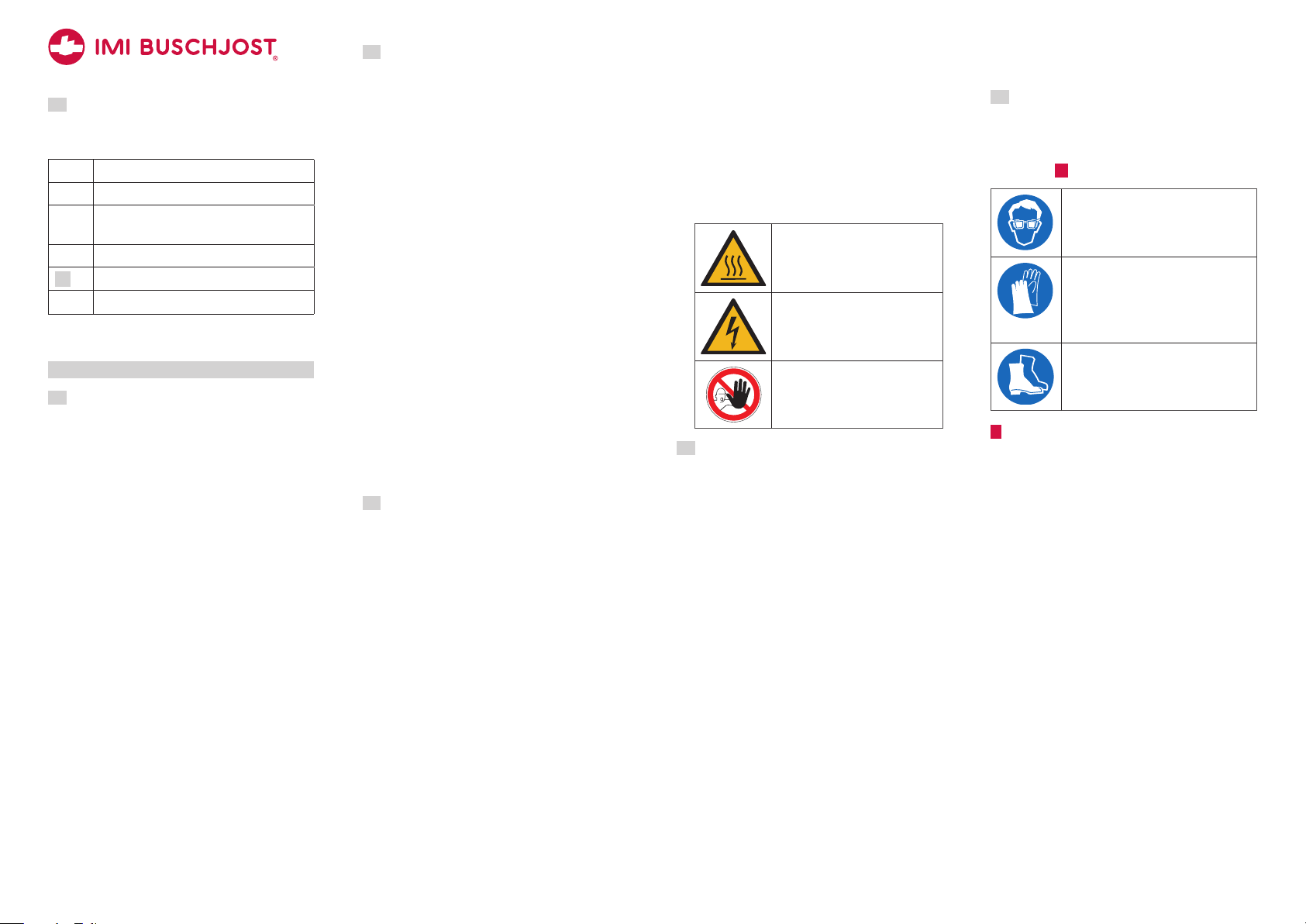
Warning sign to indicate risk of
burns at the solenoid
Warning sign to indicate electrical hazards at the solenoid
Prohibition sign to
prevent people from entering
hazardous areas
1.8
Personnel qualification
→ Ensure as operator that persons who work
on or with the valve are sufficient qualified
for this job.
→ Comprehensively train the operating per-
sonnel in terms of safety.
→ Only allow trained specialists to perform
electric connections, commissioning, maintenance and trouble shooting
Demands
Operating personnel must be instructed on
operational sequences and procedures.
Operating personnel must know its responsibilities regarding the work to be performed.
Trained specialists must possess profound
knowledge in mechanical engineering, electrical engineering, hydraulic und pneumatic.
Trained specialists must be authorized to
commission, ground and designate devices,
systems and power circuits according to the
standards of safety technology.
Trained specialists must possess profound
knowledge about design and principle of operation of the valves and the plant.
1.9
Personal protection equipment
→ Wear appropriate protection equipment.
Observe the personal protection equipment as requested in “residual risks” (see
chapter
2 ).
Protective eye glasses
to protect from escaping fluids or
exhausting compressed air
Protective gloves
resistance to cutting to protect
from sharp edges or ridges;
resistance to acids to protect from
hazardous fluids
Protective footwear
to protect from parts or tools falling
down
2
General safety instructions
These safety instructions are only related to
the single valve. In combination with other
plant components there may be other potential
dangers, which must be taken into account by
carrying out a risk analysis for the system.
→ Compare the details on rating plate and
data sheet to the operating data. The limits
for the particular application (e.g. pressure,
temperature) must not be exceeded.
→ Only perform assembly and maintenance
works when the pipe system is in depressurized state.
→ Flood the valve slowly during commissio-
ning. Fast pressurizing will cause the valve
to open briefly.
→ Strength tests with the valve seat open are
permitted maximum up to 1.5 times of the
nominal pressure rating (PN) at room temperature. The valve must not be operated
during these tests.
11/20 18
1377006.0000.10011
2
!DANGER
7 *
8
1
Hazardous electrical voltage
(>25V AC; >60V DC)
There are risks from electrical
voltage during assembly and
maintenance.
→ The electrical connection of the solenoid
must be carried out only by a qualified
electrician.
→ You may only plug or remove the device
socket in de-energized state.
→ Disconnect the power supply off the sole-
noid prior to assembly or disassembly.
! WARNING
Danger from pressurized
pipelines
Pressurized pipelines may burst
resulting in injuries.
→ Depressurize pipe system and block the
fluid flow prior to opening or unmounting
the valve.
! CAUTION
Risk of burns at the solenoid
Solenoid is heating up during
operation. Touching the solenoid
leads to risk of burns.
→ Let the solenoid to cool down before
working on the valve.
Residual risks
Weight of the valve
Phases: transport, storage,
kg
assembly, maintenance, disposal
Risk: falling off, tipping over
Personal protection equipment
(PPE): Protective footwear
Hazardous fluids
Phases: assembly, operation,
maintenance, disposal
Risk: skin contact, eye contact,
breathing vapors
PPE: protective gloves, protective eye
glasses, breathing protection
Potentially explosive atmosphere
Risk: danger of explosion
! WARNING: use solenoid an de-
vice socket with Ex-protection.
Sharp-edges and threads
Phases: transport, assembly,
maintenance, disposal
Risk: risk of cuts
PPE: protective gloves
3
Avoid damage to property
NOTICE
Deposits and dirt lead to malfunctions
If the control bores are clogged or the
core is blocked by soil the valve no longer
closes or opens.
→ Install a strainer (mesh size ≤0.25mm) in
front of the valve inlet P if necessary.
Damages through accumulation of heat
The solenoid will overheat during continuous duty if the heat can not be radiated. This shortens the service life of the
solenoid.
→ You must not cover the solenoid with paint.
→ You must not encase the solenoid in
atight housing or in a thermal insulation.
Residual risks
Pressure against valve outlet
The valve only firmly closes in flow
direction.
Fluid freezing
The valve is not designed to withstand the fluid freezing.
4
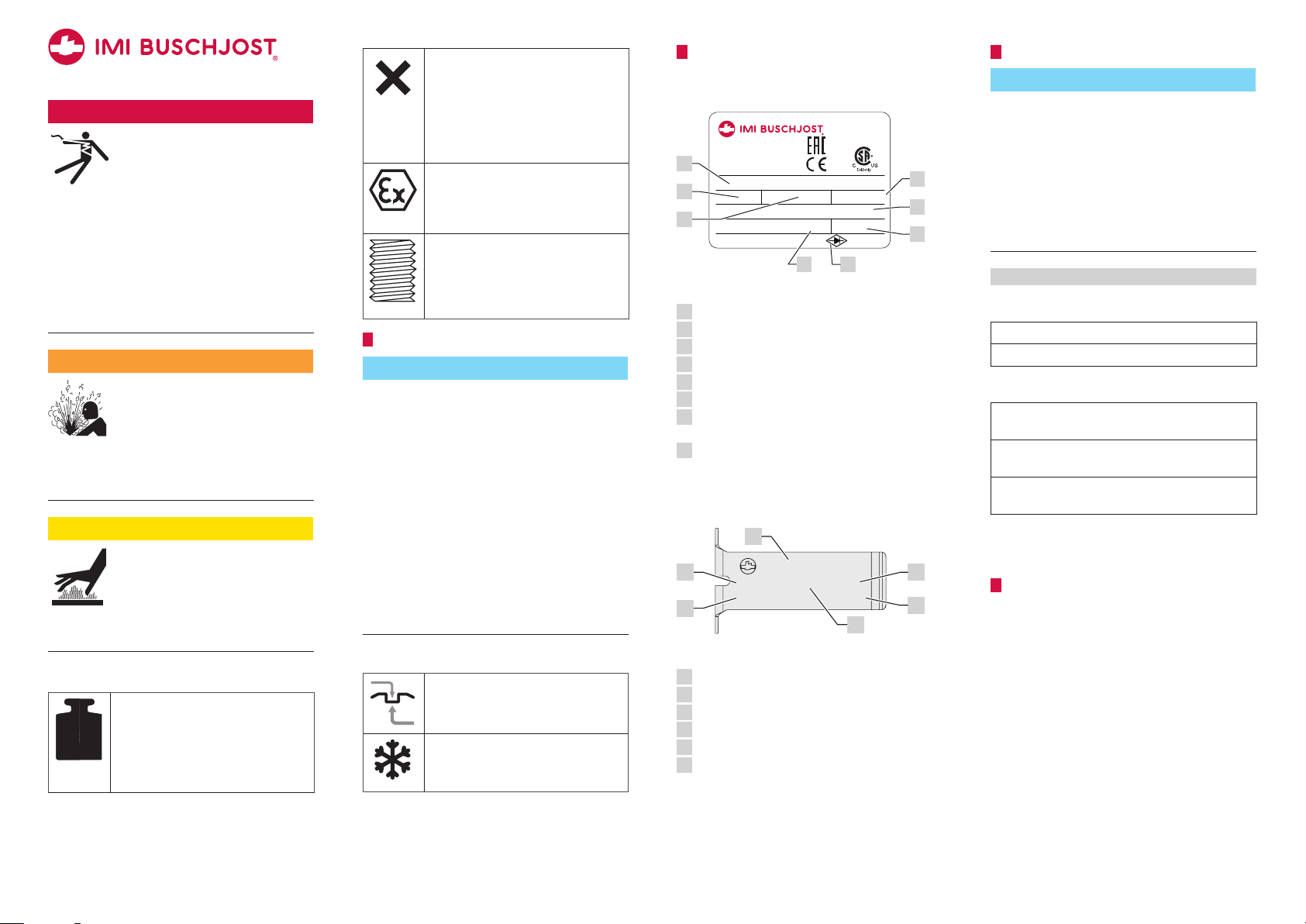
Identifying the valve
The rating plate is situated on the solenoid
body.
Made in Germany
Buschjost GmbH
D-32545 Bad Oeynhausen
1
2
3
Part no./Bestell-Nr.
8254000.9151.02400
VHz
24 00
PA
www.imi-precision.com
100%
18VA /18W
0–10
XXXX
use -plug only
4
5
bar
6
Rating plate (example)
Order number
1
Operating voltage
2
Frequency of voltage
3
Power consumption inrush/holding
4
Operating pressure range
5
Date of manufacture (week /year)
6
* if this marking is shown on the rating plate:
7
use device socket with rectifier
Duty cycle
8
An additional marking is applied to the spring
clip of the c-solenoid 9151, 9154, 9176
and 9191.
22
8254000.9150
0 - 10 bar DC only
G 1/4
xxxx
xxxx
23
6
Marking of the spring clip (example)
Order number (without voltage/frequency)
1
Operating pressure range
2
Size of connection
3
DC only (only with DC coils)
4
Date of manufacture (week /year)
5
Serial number
6
4
5
5
Transport and storage
NOTICE
Damage of the valve
Valve may be damaged if foreign particles
get into the valve.
→ Transport and store the valve dry and only
in the delivery packaging.
→ Take valve out of the packaging immedia-
tely prior to assembly.
→ Let the blanking plugs into valve connec-
tions.
Prolonged storage at −10 °C to +20 °C
Avoid during transport:
Mechanical loads: falling off, tipping over
Damages to the electrical terminal elements
Avoid during storage:
Thermal stress: permanently increased storage
temperatures; distance to heat sources < 1m
Chemical load: at the storing site through solvents, chemicals, acids, fuels and similar
Weather conditions: at construction sites strong,
watertight containers are necessary
Unfavourable storing conditions may reduce
the service life of the sealing materials
6
Function
Design
2/2-way seat valve with diaphragm as sealing
device.
Operation
The valve is electromagnetic indirectly-controlled with forced lifting.
11/20 18
1377006.0000.10011
3
P
1
Switching position: open
1
PA
The magnetic force lifts the core towards
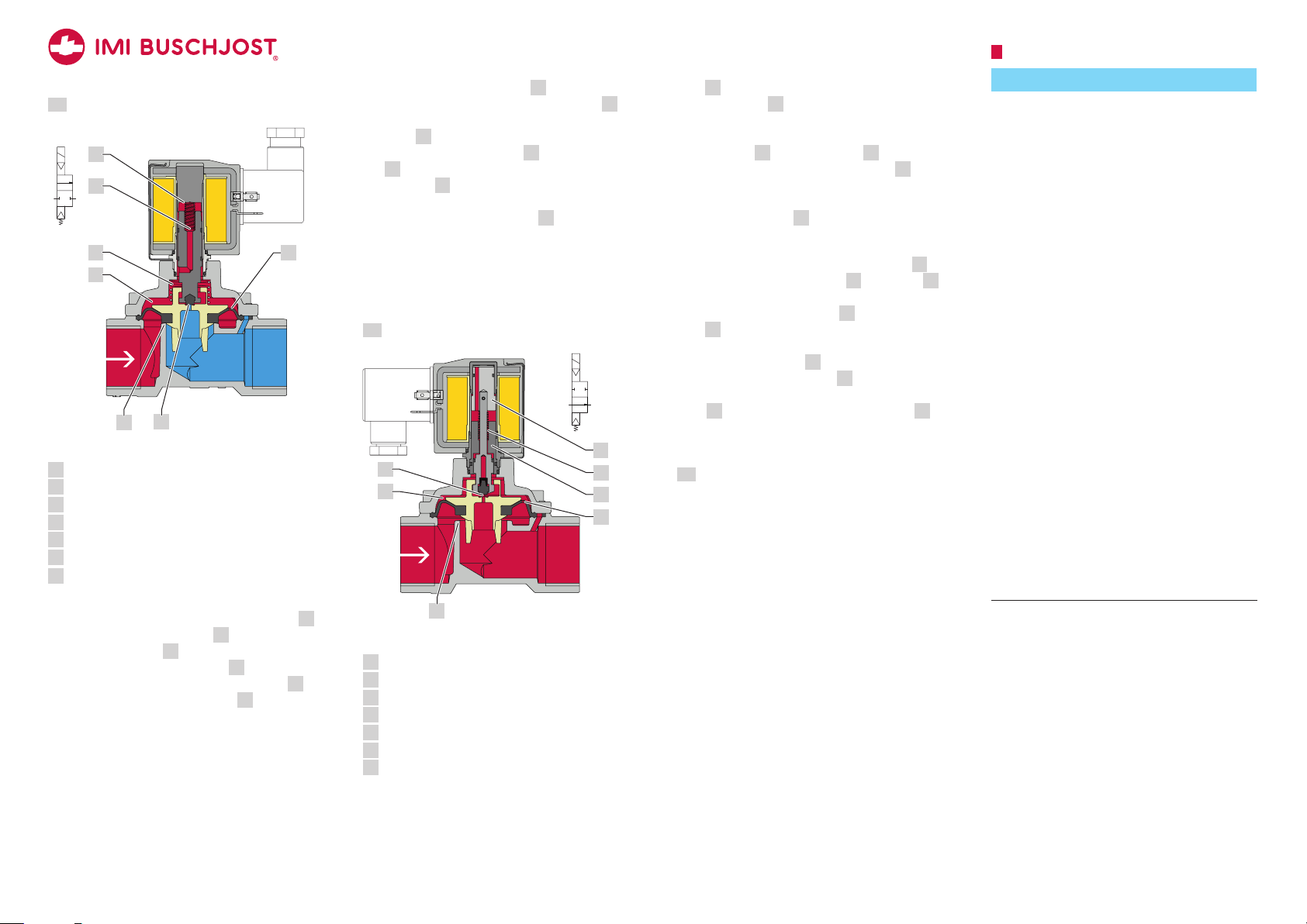
6.1
NC-valve (normally closed)
7
6
A
the magnet face of core tube
solenoid is energized. Since the pilot seat
is open the fluid pressure is reducing from
chamber
3 towards valve outlet. More fluid is
flowing off via the pilot seat
ber
3 than the amount flowing in via the
control bore
2 in the diaphragm. The
differential pressure lifts up the diaphragm
and opens the main valve seat
7 when the
5
5 to the cham-
1. Through
the mechanical coupling with the core, the
4
3
2
diaphragm is lifted into open position.
In the absence of differential pressure only
the solenoid force moves the diaphragm in the
open position.
6.2
P
5
Sectional view (NC-valve; closed)
Main valve seat
1
Control bore in the diaphragm (pressure build-up)
2
Chamber
3
Compression spring above the diaphragm
4
Pilot seat (pressure reduction)
5
Compression spring inside the core
6
Magnet face of the core tube
7
Normal position: closed
A
Due to the effect of the compression spring 6
inside the core the pilot seat
compression spring
4 presses the diaphragm
sealingly to the main valve seat
rating fluid flows through the control bore
in the diaphragm to the chamber
5 is closed. A
1 . The ope-
2
3 above the
diaphragm and increases the closing force.
NO-valve (normally open)
P
4
3
Sectional view (NO-valve; open)
Main valve seat
1
Control bore in the diaphragm (pressure build-up)
2
Chamber
3
Pilot seat (pressure reduction)
4
Pole piece
5
Compression spring inside pole piece
6
Core
7
A
7
6
5
2
Normal position: open
When the solenoid is de-energized, the pilot
seat
4 is opened by the effect of the com-
pression spring
6. Through die mechanical
coupling with the core, the diaphragm is lifted
into open position. More fluid is flowing off via
the pilot seat
amount flowing in via the control bore
4 to the chamber 3 than the
2 in
the diaphragm. The resulting differential pressure supports the opening movement.
The main valve seat
Switching position: closed
1 is open.
When the solenoid is energized, the core 7
is attracted by the pole piece
5. The core 7
presses the seal plug sealingly against the
force of compression spring
seat
4. Through the mechanical coupling
6 on the pilot
with the core, presses the diaphragm sealingly
to the main valve seat
fluid flow from the chamber
1. The outflow of the
3 is interrupted.
The operating fluid flows through the control
bore
2 in the diaphragm to the chamber 3
above the diaphragm and increases the closing
force.
6.3
Solenoid types AC/DC
The valve may be equipped without changing
of the mechanical part with an DC voltage
solenoid or AC voltage solenoid. In both cases
the permissible voltage tolerance amounts to
±10%. Special versions may cause deviations.
7
Mounting
NOTICE
Damage of the valve
The valve may be damaged through inappropriate installation.
→ Only trained and authorized specialists
may install the valve..
→ Only use appropriate tools and suitable
sealing materials.
→ Make sure that the valve is mounted in
flow direction.
→ Make sure not to distort the valve body,
particularly in case of a misaligned pipework.
There must be no mechanical loads applied to the solenoid.
→ Do not use solenoid as a lever during
mounting.
Valve only firmly closes in flow direction.
Inflow against the valve’s flow direction
may lead to the destruction of components.
→ Implement adequate measures if back flow
is to expect; for example by adding check
valves to the pipe system.
The valve subassembly may get damaged
by external loads at the operating site.
→ Protect valve from objects falling down.
→ Secure the valve against direct weather
influences and the possible effects.
11/20 18
1377006.0000.10011
4
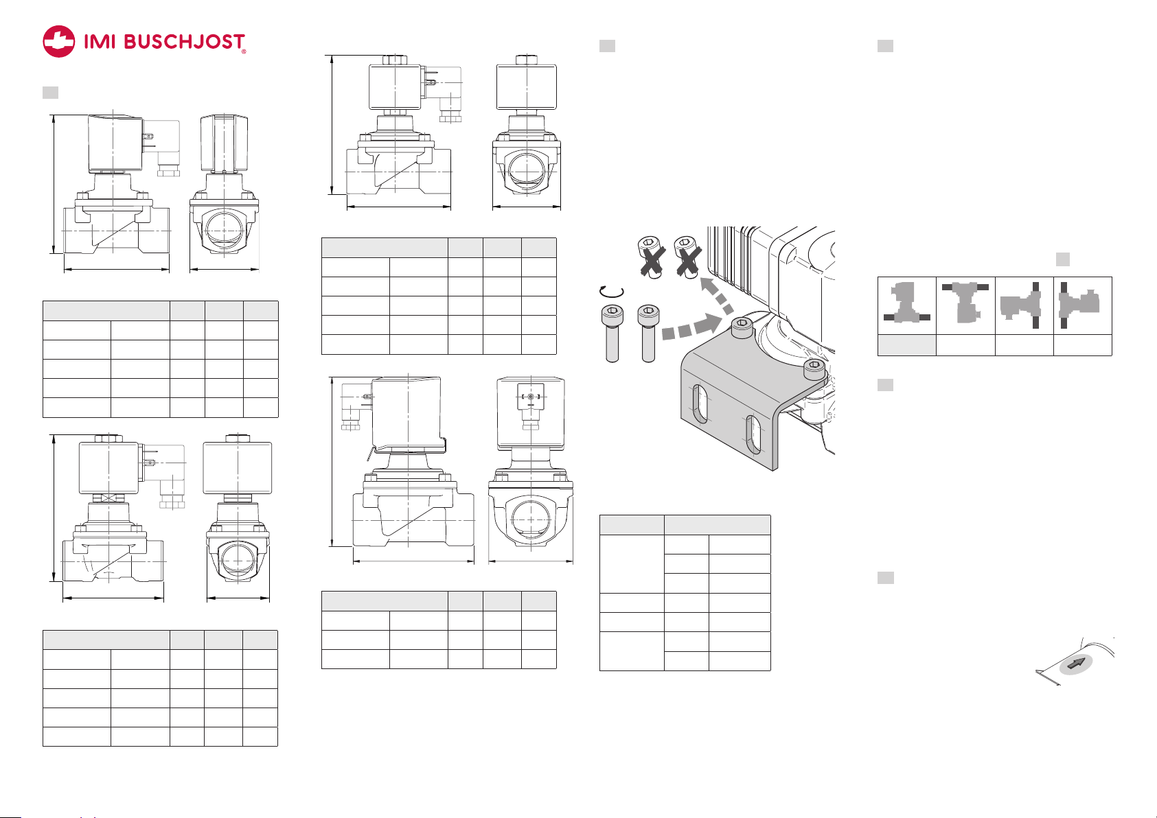
7.1
H
H
H
H
A
Valve dimensions in mm
L
with solenoid 9151, 9154, 9176, 9191
Connection size L H ø A
G 1/4 1/4 NPT 60 107 44
G 3/8 3/8 NPT 60 107 44
G 1/2 1/2 NPT 67 108 44
G 3/4 3/4 NP T 80 115 50
G 1 1 NPT 95 124 62
L
with solenoid 9301, 9304, 9356, 9326 / NC
Connection size L H ø A
G 1/4 1/4 NPT 60 108 44
G 3/8 3/8 NPT 60 108 44
G 1/2 1/2 NPT 67 110 44
G 3/4 3/4 NP T 80 117 50
G 1 1 NPT 95 12 6 62
ø A
ø A
L
with solenoid 9301, 9304, 9356 and 9326 / NO
Connection size L H ø A
G 1/4 1/4 NPT 60 10 9 44
G 3/8 3/8 NPT 60 109 44
G 1/2 1/2 NPT 67 111 44
G 3/4 3/4 NP T 80 118 50
G 1 1 NPT 95 127 62
L
with solenoid 9401 and 9404
Connection size L H ø A
G 1 1/4 1 1/4 NPT 132 186 92
G 1 1/2 1 1/2 NPT 132 186 92
G 2 2 NPT 160 200 109
ø A
ø A
7.2
Mounting accessories
Mounting bracket
With an optional mounting bracket, you can
connect the valve to an load-bearing structure
at the installation site, thus protecting against
vibration, for example.
→ Attach the mounting bracket to a long site
of valve cover before to assembly. Use the
fixing screws delivered with the mounting
bracket to achieve the necessary screw-in
depth.
Nm
Mounting bracket (example)
Available mounting brackets
Order No. Connection size
1258986 G 1/4 1/4 NP T
G 3/8 3/8 NPT
G 1/2 1/2 N PT
125 899 1 G 3/4 3/4 NPT
125 899 6 G 1 1 NPT
125 9005 G 1 1/4 1 1/4 NPT
G 1 1/2 1 1/2 NPT
7.3
Conditions of installation
Compliance with operating limits
Ensure to comply with the operating limits prior to mounting the valve. Observe the valve’s
data sheet.
Planning of the pipe system
The manufacturer recommends to include manual stop valves and drain valves in the plant
so that the pipe system may be depressurized
and drained prior to working on the valve.
Valve’s mounting position
Valve’s mounting position may be any.
preferably: Solenoid vertical on top
✔ ✔ ✔ ✔
7.4
Preparation
→ Check the valve for externally visible
damages.
→ Let the valve in its protective package prior
to mounting.
→ Make sure that there is enough free space
for disassembly the valve in case of maintenance.
→
! WARNING Depressurize the pipe
system.
→ NOTICE Clean the pipe system prior to
mounting the valve.
7.5
Mounting valve to pipeline
→ Mount the valve to the designated pipeline.
Comply with existing connections.
→ Arrange the valve according to the pipe-
line’s flow direction.
An arrow on the valve body
marks the flow direction.
11/20 18
1377006.0000.10011
5
 Loading...