

IMG STAGE LINEgital MMX-602/SW Instruction Manual
BEDIENUNGSANLEITUNG • INSTRUCTION MANUAL • MODE D’EMPLOI • ISTRUZIONI PER L’USO
VEILIGHEIDSVOORSCHRIFTEN • CONSEJOS DE SEGURIDAD
SIKKERHEDSOPLYSNINGER • SÄKERHETSFÖRESKRIFTER • TURVALLISUUDESTA
6-KANAL-MIKROFON/LINE-MISCHPULT
6-CHANNEL MICROPHONE/LINE MIXER
MIXEUR MICRO/LIGNE 6 CANAUX
MIXER MICROFONO/LINE A 6 CANALI
MMX-602/SW Best.-Nr. 20.2230
ACTIVEON
10|RL|0
SENS
010
CH1+2
CH1
OFF
ON
LINE
MIC
10|RL|0
LINE
MIC
10|RL|0
LINE
MIC
10|RL|0
LINE
MIC
10|RL|0
LINE
MIC
10|RL|0
LEVEL BAL LEVEL BAL LEVEL BAL LEVEL BAL LEVEL BAL LEVEL BAL
LINE
MIC
MID
–12 +12
dB
LOW
–12 +12
dB
HIGH
–12 +12
dB
LEFT/A
010
LEFT/B
010
LEVEL
010
POWER
PHONES
PRO 6-CHANNEL
MICROPHONE/
LINE MIXER
MMX-602/SW
1CH2CH3CH4CH5CH6
CH
TALKOVER EQUALIZER
–12 –6 –3 0dB +3 –12 –6 –3 0dB +3
STEREO
MONO
L L/A R/BR PEAK

2
wwwwww..iimmggssttaaggeelliinnee..ccoomm
Bevor Sie einschalten ...
Wir wünschen Ihnen viel Spaß mit Ihrem neuen Gerät
von „img Stage Line“. Dabei soll Ihnen diese Bedienungsanleitung helfen, alle Funktionsmöglichkeiten
kennen zu lernen. Die Beachtung der Anleitung vermeidet außerdem Fehlbedienungen und schützt Sie und
Ihr Gerät vor eventuellen Schäden durch unsachgemäßen Gebrauch.
Den deutschen Text finden Sie auf den Seiten 4– 7.
Before you switch on ...
We wish you much pleasure with your new unit by “img
Stage Line”. With these operating instructions you will be
able to get to know all functions of the unit. By following
these instructions false operations will be avoided, and
possible damage to you and your unit due to improper
use will be prevented.
You will find the English text on the pages 4– 7.
D
A
CH
GB
Avant toute mise en service ...
Nous vous remercions d’avoir choisi un appareil “img
Stage Line” et vous souhaitons beaucoup de plaisir à
l’utiliser. Cette notice a pour objectif de vous aider à
mieux connaître les multiples facettes de l’appareil et à
vous éviter toute mauvaise manipulation.
La version française se trouve pages 8– 11.
Prima di accendere ...
Vi auguriamo buon divertimento con il Vostro nuovo apparecchio “img Stage Line”. Le istruzioni per l’uso Vi possono aiutare a conoscere tutte le possibili funzioni. E
rispettando quanto spiegato nelle istruzioni, evitate di
commettere degli errori, e così proteggete Voi stessi, ma
anche l’apparecchio, da eventuali rischi per uso improprio.
Il testo italiano lo potete trovare alle pagine 8– 11.
F
B
CH
I
Voordat u inschakelt ...
Wij wensen u veel plezier met uw nieuw toestel van “img
Stage Line”. Lees de veiligheidsvoorschriften, alvorens
het toestel in gebruik te nemen. Door de veiligheidsvoorschriften op te volgen zal een slechte werking vermeden
worden, en zal een eventueel letsel aan uzelf en schade
aan uw toestel tengevolge van onzorgvuldig gebruik
worden voorkomen.
U vindt de veiligheidsvoorschriften op pagina 12.
Antes de cualquier instalación ...
Tenemos de agradecerle el haber adquirido un equipo
de “img Stage Line” y le deseamos un agrable uso. Por
favor lee las instrucciones de seguridad antes del uso.
La observación de las instrucciones de seguridad evita
operaciones erróneas y protege Vd. y vuestro aparato
contra todo daño posible por cualquier uso inadecuado.
Las instrucciones de seguridad se encuentran en la
página 12.
NL
B
E
Inden De tænder for apparatet ...
Vi ønsker Dem god fornøjelse med Deres nye “img Stage
Line” apparat. Læs oplysningerne for en sikker brug af apparatet før ibrugtagning. Følg sikkerhedsoplysningerne for
at undgå forkert betjening og for at beskytte Dem og
Deres apparat mod skade på grund af forkert brug.
Sikkerhedsoplysningerne finder De på side 12.
Förskrift
Vi önskar dig mycket nöje med din nya enhet från “img
Stage Line”. Läs gärna säkerhetsinstruktionerna innan
du använder enheten. Genom att följa säkerhetsinstruktionerna kan många problem undvikas, vilket annars kan
skada enheten.
Du finner säkerhetsinstruktionerna på sidan 13.
DK
S
Ennen virran kytkemistä…
Toivomme, että uusi “img Stage Line”-laitteesi tuo sinulle
paljon iloa ja hyötyä. Ole hyvä ja lue käyttöohjeet ennen
laitteen käyttöönottoa. Luettuasi käyttöohjeet voit käyttää laitetta turvallisesti ja vältyt laitteen väärinkäytöltä.
Käyttöohjeet löydät sivulta 13.
FIN
3
➁
12 3 4 5
➀
L
R
LINE
1
2
3
MIC
MIC
AMP
+
–
V+
MIC
LINE
BALANCE
LEVEL
PHANTOM
+12V
TALKOVER SENSITIVE
V+
ON
OFF
ACTIVE
ON
PEAK
PEAK
BASS MID TREBLE
TALKOVER
MONO
STEREO
REC L
REC R
1
2
3
+
–
LEFT/ A
RIGHT/ B
1
2
3
+
–
RIGHT/ B
PHONES
LEFT/ A
CH1
LEVEL PHONES
LEVEL
RIGHT/ B
LEVEL
LEFT/ A
VU-METER
CH1+2
CH1
JP101
MMX-602/SW
±12dB
±12dB
TALKOVER
➃
Blockschaltbild/ Block diagram
Schéma bloc /Schema di connessione
ACTIVEON
POWER
PHONES
PRO 6-CHANNEL
MICROPHONE/
LINE MIXER
MMX-602/SW
1
CH
2
CH
3
CH
4
CH
5
CH
6
CH
TALKOVER EQUALIZER
LINE
MIC
MID
–12 +12
dB
10|RL|0
LINE
MIC
10|RL|0
LINE
MIC
10|RL|0
LINE
MIC
10|RL|0
10|RL|0
SENS
010
CH1+2
CH1
OFF
ON
LINE
MIC
10|RL|0
LEVEL BAL LEVEL BAL LEVEL BAL LEVEL BAL LEVEL BAL LEVEL BAL
LINE
MIC
LOW
–12 +12
dB
HIGH
–12 +12
dB
LEFT/ A
010
LEFT/ B
010
LEVEL
010
–12 –6 –3 0dB +3 –12 –6 –3 0dB +3
STEREO
MONO
L
L/A R/BR PEAK
67 8 9 10 11 12 13 14 15 16 17
PUSH PUSH PUSH PUSH PUSH PUSH
L/A R/B REC
OUTPUT
R/B
L/A
CH 6
MIC
LINE
CH 5
LINE
MIC
CH 4
MIC
LINE
CH 3
LINE
MIC
CH 2
MIC
LINE
CH 1
LINE
MIC
230V~/50Hz
MAINS
18 19 20 21 22 23
JP101
JP201
JP301
CH1 CH3CH2
JP401
JP501
CH5
JP601
CH6CH4
CH1 – JP101
CH2 – JP201
.....
CH6 – JP601
Aus
Off
Arrêt
Ein
On
Marche
12-V-Phantomspeisung
12 V phantom power
Alimentation fantôme 12 V
Alimentazione phantom 12 V
➂

Bitte klappen Sie die Seite 3 heraus. Sie sehen
dann immer die beschriebenen Bedienelemente
und Anschlüsse.
1 Übersicht der Bedienelemente und
Anschlüsse
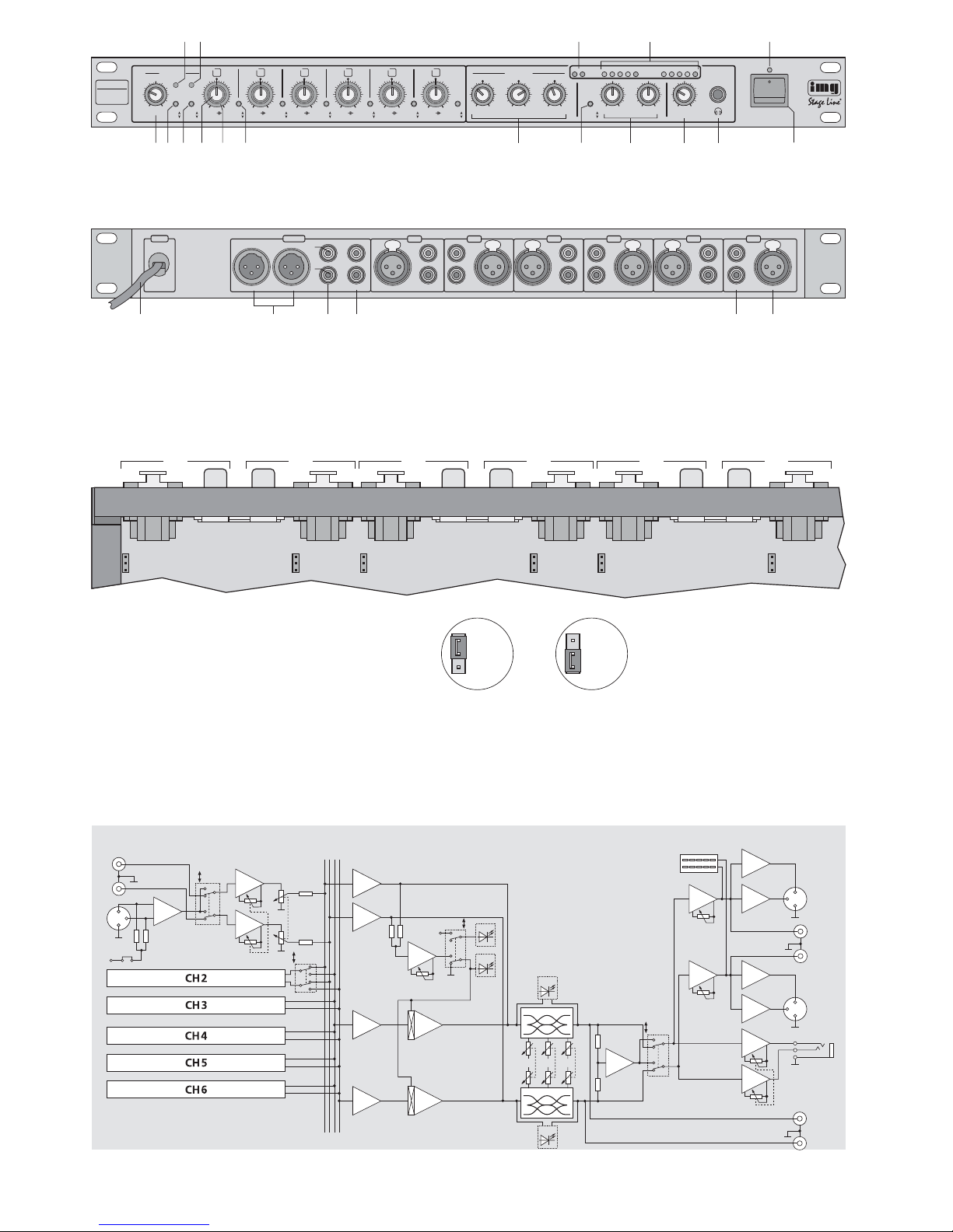
1.1 Frontseite (Abb. 1)
1 Anzeige ON
leuchtet bei eingeschalteter Talkover-Funktion,
siehe Position 7 Taste OFF/ON
2 Anzeige ACTIVE
leuchtet, wenn über die Talkover-Funktion die
Kanäle CH 2 – CH 6 bzw. CH 3 – CH 6 automatisch in der Lautstärke um 12dB abgesenkt sind
3 Übersteuerungsanzeige PEAK
bei Aufleuchten den entsprechenden Kanalpegelregler LEVEL (9) zurückdrehen
4 Pegelanzeige (2 x 5 LEDs) für die Ausgänge (19)
und (20)
5 Betriebsanzeige
6 Regler SENS für die Ansprechschwelle der Talk-
over-Funktion
7 Taste OFF/ON zum Ein-/Ausschalten der Talk-
over-Funktion
8 Umschalter CH 1+ 2/ CH1 zum Zuweisen der
Talkover-Funktion
Taste gedrückt: Liegt ein Line-Signal an Kanal
CH1 an oder erfolgt eine Mikrofondurchsage über Kanal CH 1,
werden zur besseren Verständlichkeit die Kanäle CH2 bis
CH6 in der Lautstärke um 12 dB
abgesenkt
nicht gedrückt: Liegt ein Line-Signal an Kanal
CH 1 oder CH 2 an oder erfolgt
eine Mikrofondurchsage über
CH1 oder CH 2, werden die Kanäle CH3 bis CH 6 abgesenkt
9 vorderer Drehknopf LEVEL, jeweils für die
Kanäle CH1 bis CH 6:
zum Einstellen des Kanalpegels
10 hinterer Drehring BAL, jeweils für die Kanäle
CH1 bis CH 6:
zur Balance-Einstellung der Line-Eingänge (22)
bzw. um ein Mikrofonsignal auf die gewünschte
Stelle in der Stereo-Basis zu legen
11 Eingangswahlschalter, jeweils für die Kanäle
CH1 bis CH 6
Taste gedrückt: Der Mikrofoneingang über die
XLR-Buchse (23) ist angewählt
nicht gedrückt: Der Line-Eingang über die Cinch-
Buchsen (22) ist angewählt
12 Klangregler für alle Ausgänge (19, 20, 21)
LOW = Bassregler
MID = Mittenregler
HIGH = Höhenregler
13 Umschalter STEREO / MONO für den Betriebs-
modus [nur für die Ausgänge (19) und (20) wirksam]
Taste gedrückt: Mono-Betrieb
nicht gedrückt: Stereo-Betrieb
14 Pegelregler für die Ausgänge (19) und (20)
15 Lautstärkeregler LEVEL für einen an der Buchse
PHONES (16) angeschlossenen Kopfhörer
16 6,3-mm-Klinkenbuchse PHONES zum Anschluss
eines Kopfhörers (Impedanz mindestens 2 x 8Ω)
17 Ein-/Ausschalter POWER
1.2 Rückseite (Abb. 2)
18 Netzkabel zum Anschluss an eine Steckdose
(230V~/50Hz)
19 XLR-Ausgang, symmetrisch, mono oder stereo
in Abhängigkeit vom Umschalter (13)
20 Cinch-Ausgang, asymmetrisch, mono oder
stereo in Abhängigkeit vom Umschalter (13)
21 Aufnahme-Ausgang REC (stereo, Cinch-Buch-
sen, asym.); die Aufnahmelautstärke ist von Stellung der Ausgangsregler (14) unabhängig
22 Stereo-Eingang LINE für Geräte mit Line-Aus-
gang, z. B. CD-Spieler, Tape-Deck, Tuner usw.,
jeweils für die Kanäle CH1 bis CH 6
(Cinch-Buchsen, asym.)
23 Mikrofon-Eingang MIC, jeweils für die Kanäle
CH1 bis CH 6 (XLR, symmetrisch)
1.3 Ausschnitt Innenansicht (Abb. 3)
Die Abbildung 3 zeigt die Lage der Steckbrücken
JP101 bis JP601 (Blick von oben, Geräteabdeckung
abgenommen). Mit den Brücken lässt sich eine 12-VPhantomspeisung für jeden Mikrofoneingang getrennt dazuschalten. Bei Auslieferung ab Werk ist
die Phantomspeisung ausgeschaltet. Detaillierte
Beschreibung siehe im Kapitel 4.1.
2 Hinweise für den sicheren Gebrauch
Dieses Gerät entspricht der Richtlinie für elektromagnetische Verträglichkeit 89/ 336/ EWG und der
Niederspannungsrichtlinie 73/23/EWG.
Beachten Sie auch unbedingt die folgenden Punkte:
●
Verwenden Sie das Gerät nur im Innenbereich.
Schützen Sie es vor Tropf- und Spritzwasser,
hoher Luftfeuchtigkeit und Hitze (zulässiger Einsatztemperaturbereich 0– 40°C).
●
Stellen Sie keine mit Flüssigkeit gefüllten Gefäße,
z.B. Trinkgläser, auf das Gerät.
Achtung! Das Gerät wird mit lebensgefährlicher
Netzspannung (230 V~) versorgt. Nehmen Sie deshalb nie selbst Eingriffe am
Gerät vor. Durch unsachgemäßes Vorgehen besteht die Gefahr eines elektrischen Schlages. Außerdem erlischt
beim Öffnen des Gerätes jeglicher
Garantieanspruch.
Achtung! Zum Zuschalten der Phantomspeisung
muss das Mischpult geöffnet werden.
Darum darf dies nur durch eine qualifizierte Fachkraft erfolgen.
Please unfold page 3. Then you can always see
the operating elements and connections described.
1 Operating Elements and Connections
1.1 Front panel (fig. 1)
1 Indication ON
lights up with the talkover function switched on,
see item 7 button OFF/ON
2 Indication ACTIVE
lights up if the volume of channels CH2 to CH 6
or CH3 to CH6 is automatically attenuated by
12dB via the talkover function
3 Overload indication PEAK
if it lights up, turn back the corresponding channel level control LEVEL (9)
4 Level indication (2 x 5 LEDs) for the outputs (19)
and (20)
5 Power indication
6 Control SENS for the threshold of the talkover
function
7 Button OFF/ON for switching the talkover func-
tion on and off
8 Selector switch CH1 +2/CH 1 to assign the talk-
over function
Button pressed: if a line signal is present at
channel CH1 or if a microphone
announcement is made via
channel CH1, the volume of
channels CH2 to CH 6 is
attenuated by 12 dB for better
audibility
not pressed: if a line signal is present at chan-
nel CH 1 or CH 2 or if a microphone announcement is made
via channel CH1 or CH 2, channels CH3 to CH 6 are attenuated
9 Front rotary knob LEVEL, each for channels
CH1 to CH 6:
to adjust the channel level
10 Rear rotary ring BAL, each for channels CH1 to
CH6:
to adjust the balance of the line inputs (22) or to
place a microphone signal to the desired spot in
the stereo basis
11 Input selector switch, each for channels CH 1 to
CH6
Button pressed: the microphone input is select-
ed via the XLR jack (23)
not pressed: the line input is selected via the
phono jacks (22)
12 Equalizer for all outputs (19, 20, 21)
LOW = bass range control
MID = midrange control
HIGH = high range control
13 Selector switch STEREO/MONO for the ope-
rating mode [only effective for the outputs (19)
and (20)]
Button pressed: mono operation
not pressed: stereo operation
14 Level controls for the outputs (19) and (20)
15 Volume control LEVEL for headphones con-
nected to the jack PHONES (16)
16 6.3 mm jack PHONES to connect headphones
(impedance 2 x 8Ω minimum)
17 POWER switch
1.2 Rear panel (fig. 2)
18 Mains cable for connection to a mains socket
(230V~/50 Hz)
19 XLR output, balanced, mono or stereo depend-
ing on the selector switch (13)
20 Phono output, unbalanced, mono or stereo
depending on the selector switch (13)
21 Recording output REC (stereo, phono jacks,
unbal.); the recording volume is independent of
the position of the output level controls (14)
22 Stereo input LINE for units with line output, e.g.
CD player, tape deck, tuner, etc., each for channels CH1 to CH 6 (phono jacks, unbal.)
23 Microphone input MIC, each for channels CH 1
to CH6 (XLR, balanced)
1.3 Cutout of interior view (fig. 3)
Fig. 3 shows the position of the jumpers JP101 to
JP601 (view from above, the cover of the unit is removed). With the jumpers it is possible to switch on a
12V phantom power separately for each microphone
input. Upon delivery ex factory, the phantom power is
switched off. For detailed description see chapter 4.1.
2 Safety Notes
The unit corresponds to the directive for electromagnetic compatibility 89/ 336 /EEC and to the low
voltage directive 73/23/EEC.
The following items must be observed in any case:
●
The unit is suitable for indoor use only. Protect it
against dripping water and splash water, high
humidity, and heat (ambient temperature range
0–40°C).
●
Do not place any vessels filled with liquid,
e.g. drinking glasses, on the unit.
Attention! The unit is supplied with hazardous
mains voltage (230V~). Leave servicing to skilled personnel only. Inexpert handling may cause an electric
shock hazard. Furthermore, any guarantee claim will expire if the unit has
been opened.
Attention!To switch on the phantom power, the
mixer must be opened. For this reason
this must only be done by qualified personnel.
4
GB
D
A
CH
●
Nehmen Sie das Gerät nicht in Betrieb bzw. ziehen Sie sofort den Netzstecker aus der Steckdose, wenn:
1. sichtbare Schäden am Gerät oder an der Netzanschlussleitung vorhanden sind,
2. nach einem Sturz oder Ähnlichem der Verdacht
auf einen Defekt besteht,
3. Funktionsstörungen auftreten.
Lassen Sie das Gerät in jedem Fall in einer Fachwerkstatt reparieren.
●
Eine beschädigte Netzanschlussleitung darf nur
durch den Hersteller oder eine autorisierte Fachwerkstatt ersetzt werden.
●
Ziehen Sie den Netzstecker nie am Kabel aus der
Steckdose, fassen Sie immer am Stecker an.
●
Für die Reinigung nur ein trockenes, weiches
Tuch verwenden, auf keinen Fall Chemikalien
oder Wasser.
●
Wird das Gerät zweckentfremdet, falsch angeschlossen bzw. bedient oder nicht fachgerecht repariert, kann keine Haftung für daraus resultierende Sach- oder Personenschäden und keine
Garantie für das Gerät übernommen werden.
3Einsatz- und Aufstellmöglichkeiten
Mit diesem 6-Kanal-Mischpult lassen sich Geräte
mit Line-Ausgang (z.B. CD-Spieler, Tape-Deck,
Tuner) und Mikrofone (auch phantomgespeiste) auf
einen Stereo- oder Mono-Ausgangskanal mischen.
Der MMX-602/SW eignet sich dadurch z. B. als Vormischer für eine Mikrofongruppe (Chor, Schlagzeug
usw.) oder als Mischpult in Beschallungsanlagen.
Das Gerät ist für die Montage in ein Rack
(482mm/19") vorgesehen, kann aber auch als freistehendes Tischgerät verwendet werden. Für den
Einbau in ein Rack wird 1HE (Höheneinheit) =
44,45mm benötigt.
Hinweis: Werden phantomgespeiste Mikrofone angeschlossen, muss vor dem Einbau in ein Rack die
Phantomspeisung dazugeschaltet werden (siehe
Kapitel 4.1).
4Gerät anschließen
Vor dem Anschluss bzw . vor dem V erändern von Anschlüssen das Mischpult und die anzuschließenden
Geräte ausschalten.
Soll die Talkover-Funktion (siehe Kapitel 5.3) genutzt werden, bei der Belegung der Kanäle beachten, dass ein Signal auf Kanal CH 1 oder CH 2 die
Lautstärke der Kanäle CH2 –CH 6 bzw. CH3– CH6
verringern kann. Beispiel: Kanäle CH1 und CH 2 für
die Mikrofone der Sprecher oder Akteure, die übrigen Kanäle für das Begleitprogramm oder die
Hintergrundmusik.
1) Geräte mit Line-Pegel (z. B. CD-Spieler, TapeDeck, Tuner usw.) an die sechs Cinch-Buchsenpaare LINE (22) anschließen:
weiße Buchse LEFT = linker Kanal
rote Buchse RICHT = rechter Kanal
2) Mikrofone (symmetrisch oder asymmetrisch) an
die sechs XLR-Buchsen MIC (23) anschließen.
Für phantomgespeiste Mikrofone die Phantomspeisung dazuschalten – siehe Kapitel 4.1.
Soll ein Mikrofonstecker wieder aus dem Mischpult herausgezogen werden, zur Entriegelung die
Taste PUSH der XLR-Buchse drücken.
3) Den Endverstärker für die Lautsprecher oder
ein nachfolgendes Gerät mit Line-Eingang
(Hauptmischpult, Effektgerät etc.) an die passenden Ausgangsbuchsen anschließen:
ein Gerät mit XLR-Eingang an die XLR-Buchsen
L/Aund R/B (19) und/oder
ein Gerät mit Cinch-Eingang an die Cinch-Buchsen L/A und R/B (20)
4) Ein Aufnahmegerät für Tonaufnahmen kann an
die Cinch-Buchsen REC (21) angeschlossen werden. Die Aufnahmelautstärke ist unabhängig von
der Einstellung der Ausgangspegelregler (14).
Die Aufzeichnung erfolgt unabhängig von der
Stellung des Schalters STEREO/MONO (13),
d.h. immer stereofon.
5) Über einen Kopfhörer lässt sich das Ausgangssignal des Mischpultes abhören. Dazu einen Kopfhörer (Impedanz minimal 2 x 8Ω) an die 6,3-mmKlinkenbuchse PHONES (16) anschließen.
6) Zuletzt den Netzstecker des Anschlusskabels (18)
in eine Steckdose (230V~/50Hz) stecken.
4.1 Mikrofon-Phantomspeisung dazuschalten
Um auch phantomgespeiste Mikrofone betreiben zu
können, lässt sich für jeden Mikrofoneingang getrennt eine 12-V-Phantomspeisung dazuschalten.
1) Den Netzstecker aus der Steckdose ziehen.
2) Den Gehäusedeckel abschrauben.
3) Für die gewünschten Mikrofoneingänge die entsprechenden Steckbrücken JP101 (für Kanal
CH 1) bis JP601 (für Kanal CH 6) von Aus nach
Ein, wie in Abb. 3 dargestellt, umstecken.
4) Den Gehäusedeckel wieder festschrauben.
Achtung! Zum Zuschalten der Phantomspeisung
muss das Mischpult geöffnet werden.
Darum darf dies nur durch eine qualifizierte Fachkraft erfolgen.
Vorsicht! Ist die Phantomspeisung dazuge-
schaltet, dürfen keine asymmetrischen Mikrofone an den entsprechenden Kanälen angeschlossen
werden. Anderenfalls können diese
Mikrofone beschädigt werden.
Soll das Gerät endgültig aus dem Betrieb genommen werden, übergeben Sie
es zur umweltgerechten Entsorgung
einem örtlichen Recyclingbetrieb.
●
Do not operate unit or immediately disconnect the
plug from the mains socket
1. if there is visible damage to the unit or to the
mains cable,
2. if a defect might have occurred after the unit
was dropped or suffered a similar accident,
3. if malfunctions occur.
In any case the unit must be repaired by skilled
personnel.
●
A damaged mains cable must only be repaired by
the manufacturer or authorized skilled personnel.
●
Never pull the mains cable to disconnect the mains
plug from the mains socket, always seize the plug.
●
Use a dry dust cloth only for cleaning, by no
means chemicals or water.
●
No guarantee claims for the unit and no liability for
any resulting personal damage or material damage will be accepted if the unit is used for other
purposes than originally intended, if it is not correctly connected, operated, or not repaired in an
expert way.
●
Important for U.K. Customers!
The wires in this mains lead are coloured in accordance with the following code:
blue = neutral
brown = live
As the colours of the wires in the mains lead of this
appliance may not correspond with the coloured
markings identifying the terminals in your plug,
proceed as follows:
1. The wire which is coloured blue must be connected to the terminal which is marked with the
letter N or coloured black.
2. The wire which is coloured brown must be connected to the terminal which is marked with the
letter L or coloured red.
3 Applications and Setting-up
With this 6-channel mixer it is possible to mix units
with line output (e. g. CD player, tape deck, tuner)
and microphones (also phantom-powered) to a stereo or mono output channel. Thus, the MMX-602/SW
is suitable e.g. as pre-mixer for a microphone group
(chorus, drums, etc.) or as mixer in PAsystems.
The unit is provided for mounting into a rack
(482mm/19"), but it can also be used as a table top
unit. For the installation into a rack 1 rack space =
44.45mm is required.
Note: if phantom-powered microphones are con-
nected, the phantom power must be switched on
prior to the rack installation (see chapter 4.1).
4 Connection of the Unit
Prior to the connection or changing of connections,
switch off the mixer and the units to be connected.
For using the talkover function (see chapter 5.3),
when connecting the channels observe that a signal
on channel CH1 or CH 2 can change the volume of
channels CH 2 to CH 6 or CH 3 to CH 6. Example:
CH1 and CH 2 for the microphones of speaking or
acting persons, the remaining channels for the
accompanying programme or the background
music.
1) Connect units with line level (e. g. CD player,
tape deck, tuner, etc.) to the six pairs of phono
jacks LINE (22):
white jack LEFT = left channel
red jack RIGHT = right channel
2) Connect microphones (balanced or unbalanced)
to the six XLR jacks MIC (23). For phantom-
powered microphones switch on the phantom
power – see chapter 4.1.
For disconnecting a microphone plug from the
mixer, press the button PUSH of the XLR jack for
unlocking.
3) Connect the power amplifier for the speakers or
a subsequent unit with line input (main mixer,
effect unit, etc.) to the matching output jacks:
a unit with XLR input to the XLR jacks L/A and
R/B (19) and/or
a unit with phono input to the phono jacks L/A
and R/B (20)
4) A recording unit for audio recordings can be
connected to the phono jacks REC (21). The recording volume is independent of the adjustment
of the output level controls (14). The recording is
made independent of the position of switch
STEREO/ MONO (13), i. e. it is always stereophonic.
5) Via headphones it is possible to monitor the out-
put signal of the mixer. For this purpose connect
headphones (minimum impedance 2 x 8Ω) to the
6.3 mm jack PHONES (16).
6) Finally connect the mains plug of the cable (18)
to a mains socket (230V~/50 Hz).
4.1 Switching on the microphone phantom
power
To be able to operate phantom-powered microphones
as well, it is possible to switch on a 12 V phantom
power separately for each microphone input.
1) Disconnect the mains plug from the mains socket.
2) Screw off the housing cover.
3) For the desired microphone inputs rearrange the
corresponding jumpers JP101 (for channel CH1)
to JP601 (for channel CH 6) from Off to On, as
shown in fig. 3.
4) Tightly screw on the housing cover again.
Attention! To switch on the phantom power, the
mixer must be opened. For this reason
this must only be done by qualified personnel.
Caution! If the phantom power is switched on,
no unbalanced microphones must
be connected to the corresponding
channels. Otherwise these microphones may be damaged.
If the unit is to be put out of operation
definitively, take it to a local recycling
plant for disposal which is not harmful to
the environment.
5
GB
D
A
CH
 Loading...