

IMG STAGE LINE PMX-122FX Instruction Manual
PMX-122FX Bestellnummer 20.2870
BEDIENUNGSANLEITUNG • INSTRUCTION MANUAL • MODE D’EMPLOI
ISTRUZIONI PER L’USO • GEBRUIKSAANWIJZING • MANUAL DE INSTRUCCIONES • INSTRUKCJA OBSŁUGI
SIKKERHEDSOPLYSNINGER • SÄKERHETSFÖRESKRIFTER • TURVALLISUUDESTA
POWERED MIXER
TABLE DE MIXAGE AMPLIFIÉE
MIXER AMPLIFICATO

2
wwwwww..iimmggssttaaggeelliinnee..ccoomm
Bevor Sie einschalten …
Wir wünschen Ihnen viel Spaß mit Ihrem neuen Gerät
von „img Stage Line“. Bitte lesen Sie diese Bedienungsanleitung vor dem Betrieb gründlich durch. Nur so lernen
Sie alle Funktionsmöglichkeiten kennen, vermeiden
Fehlbedienungen und schützen sich und Ihr Gerät vor
eventuellen Schäden durch unsachgemäßen Gebrauch.
Heben Sie die Anleitung für ein späteres Nachlesen auf.
Der deutsche Text beginnt auf der Seite 4.
Before switching on …
We wish you much pleasure with your new “img Stage
Line” unit. Please read these operating instructions carefully prior to operating the unit. Thus, you will get to know
all functions of the unit, operating errors will be prevented, and yourself and the unit will be protected
against any damage caused by improper use. Please
keep the oper ating instructions for later use.
The English text starts on page 12.
Avant toute installation …
Nous vous souhaitons beaucoup de plaisir à utiliser cet
appareil “img Stage Line”. Lisez ce mode dʼemploi entièrement avant toute utilisation. Uniquement ainsi, vous
pourrez apprendre lʼensemble des possibilités de fonctionnement de lʼappareil, éviter toute manipulation erronée
et vous protéger, ainsi que lʼappareil, de dommages éventuels engendrés par une utilisation inadaptée. Conservez la notice pour pouvoir vous y reporter ultérieurement.
La version française se trouve page 20.
Prima di accendere …
Vi auguriamo buon divertimento con il vostro nuovo
apparecchio di “img Stage Line”. Leggete attentamente
le istruzioni prima di mettere in funzione lʼapparecchio.
Solo così potete conoscere tutte le funzionalità, evitare
comandi sbagliati e proteggere voi stessi e lʼapparecchio
da eventuali danni in seguito ad un uso improprio. Conservate le istruzioni per poterle consultare anche in
futuro.
Il testo italiano inizia a pagina 28.
D
A
CH
GB
Antes de la utilización …
Le deseamos una buena utilización para su nue vo aparato “img Stage Line”. Por favor, lea estas in s trucciones
de uso atentamente antes de ha cer funcionar el aparato.
De esta manera conocerá todas las funciones de la unidad, se pre vendrán errores de operación, usted y el apa rato estarán protegidos en contra de todo daño cau sado
por un uso inadecuado. Por favor, guarde las instrucciones para una futura utilización.
La versión española comienza en la página 44.
Voor u inschakelt …
Wij wensen u veel plezier met uw nieuwe apparaat van
“img Stage Line”. Lees deze gebruikershandleiding grondig door, alvorens het apparaat in gebruik te nemen.
Alleen zo leert u alle functies kennen, vermijdt u foutieve
bediening en behoedt u zichzelf en het apparaat voor
eventuele schade door ondeskundig gebruik. Bewaar de
handleiding voor latere raadpleging.
De Nederlandstalige tekst vindt u op pagina 36.
Przed uruchomieniem …
Życzymy zadowolenia z nowego produktu “img Stage
Line”. Dzięki tej instrukcji obsługi będą państwo w stanie
poznać wszystkie funkcje tego urządzenia. Stosując się
do instrukcji unikną państwo błędów i ewentualnego
uszkodzenia urządzenia na skutek nieprawidłowego
użytkowania. Prosimy zachować instrukcję.
Tekst polski zaczyna się na stronie 51.
Før du tænder …
Tillykke med dit nye “img Stage Line” produkt. Læs sikkerhedsanvisningerne nøje før ibrugtagning, for at
beskytte Dem og enheden mod skader, der skyldes forkert brug. Gem venligst denne betjeningsvejledning til
senere brug.
Sikkerhedsanvisningerne findes på side 58.
Innan du slår på enheten …
Vi önskar dig mycket glädje med din nya “img Stage
Line” produkt. Läs igenom säkerhetsföre skrifterna innan
en heten tas i bruk för att undvika skador till följd av
felaktig hantering. Behåll instruktionerna för framtida
bruk.
Säkerhetsföreskrifterna återfinns på sidan 58.
Ennen kytkemistä …
Toivomme Sinulle paljon miellyttäviä hetkiä uuden “img
Stage Line” laitteen kanssa. Ennen laitteen käyttöä pyydämme Sinua huolellisesti tutustumaan turvallisuusohjeisiin. Näin vältyt vahingoilta, joita virheellinen laitteen
käyttö saattaa aiheuttaa. Ole hyvä ja säilytä käyttöohjeet
myöhempää tarvetta varten.
Turvallisuusohjeet löytyvät sivulta 59.
I
ENL
PL DK
S
FIN
B
F
B
CH
3
54 55 56 57 58

4
D
A
CH
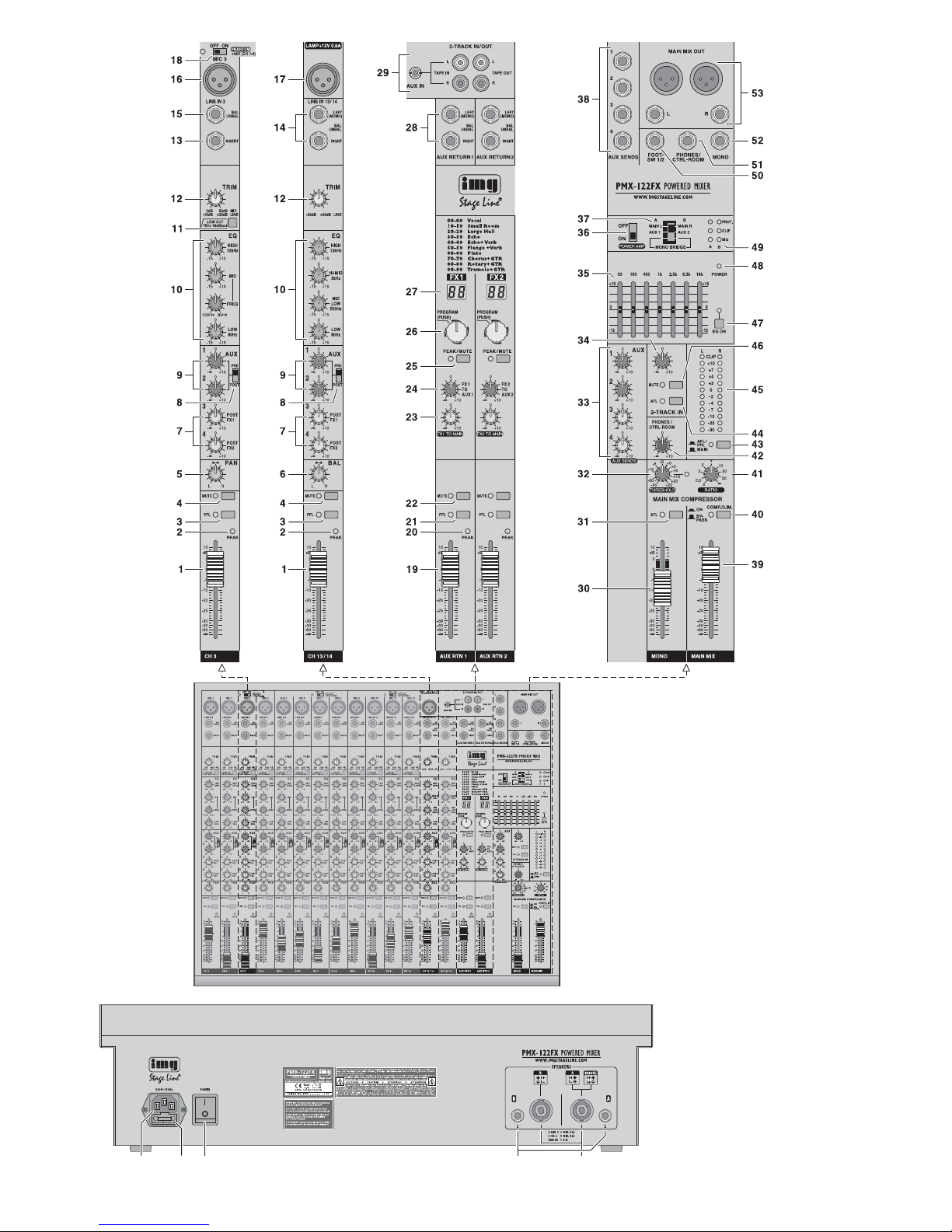
Auf der ausklappbaren Seite 3 finden Sie
alle beschriebenen Bedienelemente und An schlüsse.
Inhalt
1 Übersicht der Bedienelemente
und Anschlüsse . . . . . . . . . . . . . . . . . . 4
1.1 Eingangskanäle . . . . . . . . . . . . . . . . . . . 4
1.2 Effektprozessoren,
AUX RETURN und TAPE IN / OUT . . . . 4
1.3 Ausgangsfeld . . . . . . . . . . . . . . . . . . . . . 5
1.4 Rückseite . . . . . . . . . . . . . . . . . . . . . . . . 5
2 Hinweise für den sicheren Gebrauch .5
3 Einsatzmöglichkeiten . . . . . . . . . . . . . . 5
4 Geräte anschließen . . . . . . . . . . . . . . . . . 6
4.1 Tonquellen . . . . . . . . . . . . . . . . . . . . . . . 6
4.1.1 Mikrofone . . . . . . . . . . . . . . . . . . . . . . . 6
4.1.2 Line-Tonquellen . . . . . . . . . . . . . . . . . . 6
4.2 Effektgeräte . . . . . . . . . . . . . . . . . . . . . . 6
4.2.1 Effektgeräte einschleifen . . . . . . . . . . . 6
4.2.2 Ausspielwege verwenden . . . . . . . . . . 6
4.3 Aufnahmegerät . . . . . . . . . . . . . . . . . . . 6
4.4 Regie-Monitoranlage oder
Kopfhörer anschließen . . . . . . . . . . . . . . 6
4.5 Monitoranlage für die Musiker . . . . . . . . 6
4.6 Zusätzliche Verstärker
für das Summensignal . . . . . . . . . . . . . . 6
4.7 Lautsprecher . . . . . . . . . . . . . . . . . . . . . . 6
4.8 Pultleuchte . . . . . . . . . . . . . . . . . . . . . . . 7
4.9 Fußtaster für die Effektprozessoren . . . . 7
4.10 Stromversorgung . . . . . . . . . . . . . . . . . . 7
5 Bedienung . . . . . . . . . . . . . . . . . . . . . . . 7
5.1 Ein- und Ausschalten . . . . . . . . . . . . . . . 7
5.2 Aussteuerung der Eingangskanäle . . . . 7
5.3 Eingangssignale mischen . . . . . . . . . . . . 7
5.4 Signalkompressor verwenden . . . . . . . . 8
5.5 Monitor-Ausspielwege einstellen . . . . . . 8
5.6 Effekte zumischen . . . . . . . . . . . . . . . . . 8
5.6.1 Verwendung der
internen Effektprozessoren . . . . . . . . . 8
5.6.2 Externe Effektgeräte . . . . . . . . . . . . . . 9
5.7 Abhören über einen Kopfhörer
oder eine Regie-Monitoranlage . . . . . . . 9
6 Technische Daten . . . . . . . . . . . . . . . . 10
6.1 Steckerbelegung . . . . . . . . . . . . . . . . . . 10
Blockschaltbild . . . . . . . . . . . . . . . . . . . 61
1 Übersicht der Bedienelemente
und Anschlüsse
1.1 Eingangskanäle
Abb. 1 Mono-Eingangskanal CH 3
Alle Mono-Eingangskanäle
(CH 1 … CH 12) sind identisch.
Abb. 2 Stereo-Eingangskanal CH 13/14
Der zweite Stereo-Eingangskanal
(CH 15/16) ist bis auf den Pultleuchtenanschluss (17) identisch.
1 Kanalfader für die Kanallautstärke und zum
Ein- und Ausblenden des Kanalsignals
2 LED PEAK zeigt durch kurzes Aufleuchten
an, dass der maximale unverzerrte Signalpegel erreicht ist. Leuchtet sie länger, wird der
Kanal übersteuert. Dann den Regler TRIM
(12) entsprechend zurückdrehen.
3 Taste PFL mit Kontroll-LED zum Vorhören
des zugehörigen Kanals über einen an der
Buchse PHONES / CTRL-ROOM (51) angeschlossenen Kopfhörer oder über eine an
dieser Buchse angeschlossene Monitoranlage. Zum Anzeigen des Kanalsignals durch
die Pegelanzeige (45) muss auch die Taste
(43) unter der Anzeige hineingedrückt sein.
4 Taste MUTE mit Kontroll-LED zum Stumm-
schalten des Kanals
5 Panoramaregler PAN zum Platzieren des
Mono-Signals im Stereo-Klangbild
6 Balanceregler BAL für die Stereokanäle
7 Regler AUX 3 und AUX 4 zum Mischen des
Kanalsignals auf die Ausspielwege AUX 3
und AUX 4 (post-fader)
Diese Ausspielwege dienen als Effektwege
für die internen Effektprozessoren und für
externe Effektgeräte.
8 Umschalter PRE / POST gemeinsam für die
Ausspielwege AUX 1 und AUX 2
Position POST: Signalabgriff post-fader
Das Kanalsignal wird nach dem Fader (1)
auf den Ausspielweg gegeben.
Position PRE: Signalabgriff pre-fader
Das Kanalsignal wird vor dem Fader auf
den Ausspielweg gegeben.
9 Regler AUX 1 und AUX 2 zum Mischen des
Kanalsignals auf die Ausspielwege AUX 1
und AUX 2 (umschaltbar pre-fader / post-fader)
Diese Ausspielwege können als Monitorwege zur Beschallung der Musiker genutzt
werden oder als Effektwege für externe
Effektgeräte.
10 Klangregler
LOW für die Bässe: ±15 dB bei 80 Hz
MID FREQ
1
zum Einstellen der Filterfre-
quenz (100 Hz – 8 kHz) im Mittenbereich
MID
1
für die Mitten:
±15 dB bei 100 Hz–8kHz
MID LOW
2
für die unteren Mitten:
±15 dB bei 500 Hz
HI-MID
2
für die oberen Mitten:
±15 dB bei 3 kHz
HIGH für die Höhen: ±15 dB bei 12 kHz
1
nur bei den Monokanälen
2
nur bei den Stereokanälen
11 Taste LOW CUT für den Hochpass
Bei hineingedrückter Taste werden unerwünschte Signalanteile unter 75 Hz unterdrückt, z. B. Trittschall.
12 Regler TRIM zum Einstellen der Eingangs-
verstärkung
13 Buchse INSERT (6,3-mm-Klinkenbuchse)
zum Einschleifen von Effektgeräten (z. B.
Kompressoren) in die Mono-Eingangskanäle
Steckeranschlüsse:
Spitze = Send (Ausgang)
Ring = Return (Eingang)
Schaft = Masse
14 Stereo-Eingang LINE IN (6,3-mm-Klinken -
buchsen, sym.) für den Anschluss einer Signalquelle mit Line-Ausgangspegel (z. B.
Musikinstrument, CD/ MP3-Spieler)
Hinweis: Beim Anschluss eines Mono-Geräts nur
die Buchse LEFT (MONO) verwenden. Das Signal
wird dann intern auf den rechten und linken Kanal
geleitet.
15 Mono-Eingang LINE IN (6,3-mm-Klinkenbuch -
se, sym.) für den Anschluss einer Signalquelle mit Line-Ausgangspegel
16 Eingang MIC für den Anschluss eines Mikro-
fons (XLR-Buchse, sym.)
Für die Mikrofoneingänge lässt sich die Phantomspeisung zuschalten,
Position 18.
17 XLR-Buchse LAMP zum Hineinstecken einer
Schwanenhalslampe für die Pultbeleuchtung
(12 V /500 mA max.)
18 Ein- /Ausschalter PHANTOM mit Kontroll-
LED für die 48-V-Phantomspeisung von je weils vier Mikrofoneingängen
Beachten Sie bitte die Vorsichtshinweise zur
Phantomspeisung in Kapitel 4.1.1.
1.2 Effektprozessoren,
AUX RETURN und TAPE IN / OUT
19 Fader AUX RTN 1 und 2 zum Mischen der
Signale an den Eingängen AUX RETURN 1
und 2 (28) auf das Summensignal
20 LED PEAK zeigt durch kurzes Aufleuchten
an, dass der maximale unverzerrte Signal pegel erreicht ist. Leuchtet sie länger, wird
der Kanal übersteuert. Dann den Fader AUX
RTN (19) entsprechend zurückziehen.
21 Taste PFL mit Kontroll-LED zum Vorhören des
zugehörigen RETURN-Eingangs über einen
an der Buchse PHONES / CTRL-ROOM (51)
angeschlossenen Kopfhörer oder über eine
an dieser Buchse angeschlossene Monitoranlage. Zum Anzeigen des RETURN-Signals
durch die Pegelanzeige (45) muss auch die
Taste (43) unter der Anzeige hineingedrückt
sein.
22 Taste MUTE mit Kontroll-LED zum Stumm-
schalten des RETURN-Signals
23 Regler FX 1 TO MAIN und FX 2 TO MAIN
zum Mischen der internen Effektsignale auf
das Summensignal
24 Regler FX 1 TO AUX 1 und FX 2 TO AUX 2
zum Mischen der internen Effektsignale auf
die Ausspielwege AUX 1 und AUX 2
25 Tasten MUTE zum Stummschalten der inter-
nen Effektprozessoren
Bei stummgeschaltetem Effektprozessor
leuchtet zur Kontrolle die LED neben der
Taste kontinuierlich. Bei eingeschaltetem
Effektprozessor zeigt die LED Übersteuerungen des Prozessors an.
26 Knöpfe PROGRAM zur Effektauswahl: Den
Knopf drehen, bis im Display (27) die Effektnummer blinkend angezeigt wird, dann zur
Bestätigung den Knopf kurz drücken.
27 Displays zur Anzeige der gewählten Effekt-
nummer
28 Eingänge AUX RETURN 1 und 2 (6,3-mm-
Klinkenbuchsen, sym.), können als Eingänge
für Effektgeräte oder für zusätzliche LineTonquellen verwendet werden

5
D
A
CH
Die Eingangssignale werden mit den Fadern
AUX RTN 1 und 2 (19) auf das Summensignal gemischt.
Hinweis: Beim Anschluss eines Mono-Geräts nur
die Buchse LEFT (MONO) verwenden. Das Signal
wird dann intern auf den rechten und linken Kanal
ge leitet.
29 Ein- und Ausgangsbuchsen (Cinch) für ein
Aufnahmegerät; als Eingang ist auch eine
3,5-mm-Klinkenbuchse vorhanden
An den Buchsen TAPE OUT liegt das Summensignal nach dem Fader MAIN MIX (39)
an.
Das Signal der Buchsen AUX IN / TAPE IN
lässt sich mit dem Regler 2-TRACK IN (34)
auf das Summensignal mischen.
1.3 Ausgangsfeld
30 Fader MONO für den Pegel des Mono-Sum-
mensignals an der Buchse MONO (52) und
für die Lautstärke des Mono-Summensignals, wenn es auf die Endstufe gegeben wird
[Schiebeschalter (37) in der Position MONO
BRIDGE]
31 Taste AFL mit Kontroll-LED zum Abhören
des Mono-Summensignals nach dem Fader
MONO (30) über einen an der Buchse
PHONES / CTRL-ROOM (51) angeschlossenen Kopfhörer oder über eine an dieser
Buchse angeschlossene Monitoranlage. Zum
Anzeigen des Signals durch die Pegelanzeige (45) muss auch die Taste (43) unter der
Anzeige hineingedrückt sein.
32 Regler THRESHOLD zum Einstellen des Ein-
satzpunktes (Schwellwert), ab dem das Stereo-Summensignal komprimiert werden soll
33 Pegelregler AUX 1 – 4 für die Gesamtsignale
der vier Ausspielwege, die an den Ausgängen AUX SENDS (38) zur Verfügung stehen;
die Signale der Wege AUX 3 und 4 werden
auch auf die internen Effektprozessoren ge leitet
34 Regler 2-TRACK IN zum Mischen des Sig-
nals der Buchsen AUX IN / TAPE IN (29) auf
das Summensignal
35 7-Band-Equalizer für das Summensignal
36 Ein- /Ausschalter POWER AMP für die End-
stufe
37 Betriebsartenschalter für die Endstufe
obere Position = Die Endstufe arbeitet im
Stereo-Betrieb und verstärkt das linke und
rechte Summensignal.
mittlere Position = Die Endstufe arbeitet im
2-Kanal-Betrieb und verstärkt im Kanal A
das Signal des Ausspielwegs AUX 1 und
im Kanal B das Signal des Ausspielwegs
AUX 2
untere Position = Die Endstufe arbeitet im
Brückenbetrieb (doppelte Ausgangsleistung an einem 8-Ω-Lautsprecher) und verstärkt das Mono-Summensignal.
38 Ausgänge AUX SENDS 1 – 4 (6,3-mm-
Klinkenbuchsen, asym.) für die vier Ausspielwege
39 Fader MAIN MIX für den Pegel des Stereo-
Summensignals am Ausgang MAIN MIX
OUT (53) und für die Lautstärke des StereoSummensignals, wenn es auf die Endstufe
gegeben wird [Schiebeschalter (37) in der
Position MAIN L / MAIN R]
40 Taste COMP/ LIM mit Kontroll-LED zum Ein-
schalten des Kompressors für das StereoSummensignal
41 Regler RATIO zum Einstellen des Kompres-
sionsverhältnisses
42 Lautstärkeregler PHONES / CTRL-ROOM für
den Ausgang PHONES / CTRL-ROOM (51)
43 Taste AFL / PFL – MAIN mit Kontroll-LED zur
Auswahl des Signals, das die Pegelanzeige
(45) anzeigen soll und das auf den Ausgang
PHONES / CTRL-ROOM (51) gegeben werden soll
Taste ausgerastet:
Das Stereo-Summensignal nach dem
Fader MAIN MIX (39) wird angezeigt und
auf den Ausgang PHONES / CTRL-ROOM
gegeben.
Taste hineingedrückt:
Das Signal eines Kanals, dessen Taste
PFL (3, 21) oder AFL (31, 44) gedrückt ist,
wird angezeigt und auf den Ausgang
PHONES / CTRL-ROOM gegeben.
44 Taste AFL mit Kontroll-LED zum Abhören
des Signals der Buchsen AUX IN / TAPE IN
(29) nach dem Regler 2-TRACK IN (34) über
einen an der Buchse PHONES / CTRLROOM (51) angeschlossenen Kopfhörer
oder über eine an dieser Buchse angeschlossene Monitoranlage. Zum Anzeigen
des Signals durch die Pegelanzeige (45)
muss auch die Taste (43) unter der Anzeige
hineingedrückt sein.
45 Pegelanzeige; zeigt den Pegel des Signals
an, das zum Abhören über den Ausgang
PHONES / CTRL-ROOM (51) angewählt ist,
siehe Position 43
46 Taste MUTE mit Kontroll-LED zum Stumm-
schalten des Signals am Eingang AUX IN /
TAPE IN (29)
47 Taste EQ ON mit Kontroll-LED zum Einschal-
ten des Equalizers für das Summensignal
48 Betriebsanzeige POWER
49 Kontrollanzeigen A für den linken Kanal der
Endstufe und B für den rechten Kanal
SIG = Signalanzeige
CLIP = Übersteuerungsanzeige
PROT. = Die Schutzschaltung hat die Endstufe
abgeschaltet, z. B. bei Überhitzung
oder bei einem Kurzschluss an einer
der Buchsen SPEAKERS (57, 58).
50 Anschluss FOOT-SW 1/ 2 (6,3-mm-Klinken -
buchse, 3-polig) für zwei Fußtaster zum Ein-/
Ausschalten der internen Effektprozessoren
(Anschluss siehe Kapitel 4.9)
51 Ausgang PHONES / CTRL-ROOM (6,3-mm-
Klinkenbuchse, asym.) für den Anschluss
eines Stereo-Kopfhörers (Impedanz min. 8 Ω)
oder einer Regie-Monitoranlage
52 Line-Ausgang MONO (6,3-mm-Klinken buch -
se, asym.) für das Mono-Summensignal
53 Line-Ausgang MAIN MIX OUT für das Ste-
reo-Summensignal (XLR, sym. und 6,3-mmKlinkenbuchsen, asym.)
1.4 Rückseite
54 Netzbuchse zum Anschluss an eine Steck-
dose (230 V~ / 50 Hz) über das beiliegende
Netzkabel
55 Halterung für die Netzsicherung
Eine geschmolzene Sicherung nur durch
eine gleichen Typs ersetzen.
56 Ein- /Ausschalter POWER
57 Lautsprecherbuchsen (6,3-mm-Klinke)
alternativ zu den Anschlüssen (58)
58 Lautsprecherbuchsen (SPEAKON
®
-kompatibel) alternativ zu den 6,3-mm-Klinken buch sen (57)
2 Hinweise für den
sicheren Gebrauch
Das Gerät entspricht allen relevanten Richtlinien
der EU und ist deshalb mit
gekennzeichnet.
Beachten Sie auch unbedingt folgende Punkte:
G
Verwenden Sie das Gerät nur im Innenbereich
und schützen Sie es vor Tropf- und Spritzwasser, hoher Luftfeuchtigkeit und Hitze (zulässiger Einsatztemperaturbereich 0 – 40 °C).
G
Stellen Sie keine mit Flüssigkeit gefüllten Ge fäße z. B. Trinkgläser, auf das Gerät.
G
Die in dem Gerät entstehende Wärme muss
durch Luftzirkulation abgegeben werden.
Decken Sie darum die Lüftungsöffnungen des
Gehäuses nicht ab.
G
Nehmen Sie das Gerät nicht in Betrieb und
ziehen Sie sofort den Netzstecker aus der
Steckdose,
1. wenn sichtbare Schäden am Gerät oder am
Netzkabel vorhanden sind,
2. wenn nach einem Sturz oder Ähnlichem der
Verdacht auf einen Defekt besteht,
3. wenn Funktionsstörungen auftreten.
Geben Sie das Gerät in jedem Fall zur Reparatur in eine Fachwerkstatt.
G
Ziehen Sie den Netzstecker nie am Kabel aus
der Steckdose, fassen Sie immer am Stecker
an.
G
Verwenden Sie für die Reinigung nur ein trockenes, weiches Tuch, niemals Wasser oder
Chemikalien.
G
Wird das Gerät zweckentfremdet, nicht richtig
angeschlossen, falsch be dient oder nicht fachgerecht repariert, kann keine Haftung für
daraus resultierende Sach- oder Personenschäden und keine Garantie für das Gerät
übernommen werden.
3 Einsatzmöglichkeiten
Dieses Audio-Mischpult mit integrierter StereoEndstufe (Klasse D, 2 × 400 WRMS an 4-Ω-Laut sprechern) ist für vielfältige Beschallungs- und
Aufnahmezwecke geeignet. Es ist als Tischgerät
ausgelegt und verfügt über 12 Mono- und 2 Stereo-Eingangskanäle zum Anschluss von Mikrofonen (auch phantomgespeisten) und Tonquellen mit Line-Ausgangspegel (z. B. Instrumente,
Abspielgeräte).
Die Eingangssignale lassen sich auf einen
Stereo-Summenkanal, einen Mono-Summenkanal und auf vier Ausspielwege mischen. Zum
Zumischen von Effekten sind zwei digitale
Effektprozessoren vorhanden. Zum Abhören der
Tonmischung oder zum Vorhören einzelne
Kanalsignale lässt sich ein Kopfhörer oder eine
Monitoranlage anschließen.
Soll das Gerät endgültig aus dem
Betrieb genommen werden, übergeben
Sie es zur umweltgerechten Entsorgung einem örtlichen Recyclingbetrieb.
WARNUNG Dieses Gerät wird mit lebensge-
fährlicher Netzspannung versorgt.
Nehmen Sie deshalb nie selbst
Eingriffe am Gerät vor und stecken
Sie nichts durch die Lüftungsöffnungen. Es besteht die Gefahr
eines elektrischen Schlages.
6
D
A
CH
4 Geräte anschließen
Um Störgeräusche zu vermeiden, vor dem Herstellen / Trennen von Verbindungen das Mischpult ausschalten oder in den entsprechenden
Kanälen die zugehörigen Regler zudrehen / die
zugehörigen Fader zuziehen.
4.1 Tonquellen
In den Mono-Eingangskanälen kann nicht zwischen dem Mikrofoneingang (16) und dem LineEingang (15) umgeschaltet werden. Darum pro
Mono-Kanal nur einen von beiden Eingängen
anschließen.
4.1.1 Mikrofone
Mikrofone an die symmetrisch beschalteten
XLR-Buchsen MIC (16) anschließen. Für phantomgespeiste Mikrofone lässt sich für jeweils
vier Mikrofoneingänge mit den Schaltern PHANTOM (18) eine 48-V-Phantomspeisung einschalten. Bei aktivierter Phantomspeisung leuchtet
die LED neben dem Schalter.
4.1.2 Line-Tonquellen
Tonquellen mit Line-Signalpegel (z. B. Empfänger von drahtlosen Mikrofonsystemen, Effektgeräte, Instrumente, Abspielgeräte) an die 6,3-mmKlinkenbuchsen LINE IN (14, 15) der Eingangskanäle anschließen. Die Buchsen sind symmetrisch be schaltet. Es lassen sich aber auch Geräte mit asymmetrisch beschaltetem Ausgang über
zweipolige Klinkenstecker anschließen.
— Mono-Geräte an die Buchsen (15) der Mono-
Kanäle CH 1 bis CH 12 anschließen. Soll an
einen Stereo-Kanal ein Mono-Gerät angeschlossen werden, nur die obere Buchse
LEFT (MONO) verwenden. Das Mono-Signal
wird dann intern auf den rechten und linken
Kanal geleitet.
— Stereo-Geräte an die Buchsen (14) der Ste-
reo-Kanäle CH 13 /14 und CH 15 /16 anschließen.
Stereo-Geräte können aber auch an zwei
Mono-Kanäle angeschlossen werden. Bei
dem Mono-Kanal, an dem der linke Kanal
des Stereo-Gerätes angeschlossen ist, den
Regler PAN (5) ganz nach links in die Position „L“ drehen und bei dem Mono-Kanal, an
dem der rechte Kanal angeschlossen ist, den
Regler PAN ganz nach rechts in die Position
„R“ drehen.
Zum Anschluss von zusätzlichen Line-Quellen
können auch folgende Stereo-Eingänge genutzt
werden:
1. die Eingänge AUX RETURN 1 und 2 (28)
Beim Anschluss eines Mono-Geräts nur die
Buchse LEFT (MONO) verwenden, das
Mono-Signal wird dann intern auf den linken
und rechten Kanal geleitet.
2. der Eingang AUX IN/TAPE IN (29)
z. B. zum Anschluss eines CD-Spielers für
Hintergrundmusik in den Spielpausen
4.2 Effektgeräte
4.2.1 Effektgeräte einschleifen
Effektgeräte (z. B. Geräte zur Klangbearbeitung
wie Kompressoren, Equalizer, Noise-Gates) lassen sich direkt in die Mono-Kanäle einschleifen:
Das Kanalsignal wird nach dem Regler TRIM
(12) und dem Low-Cut-Filter (11) ausgekoppelt,
läuft komplett über das Effektgerät und wird an
der gleichen Stelle des Signalwegs wieder in
den Kanal zurückgeführt.
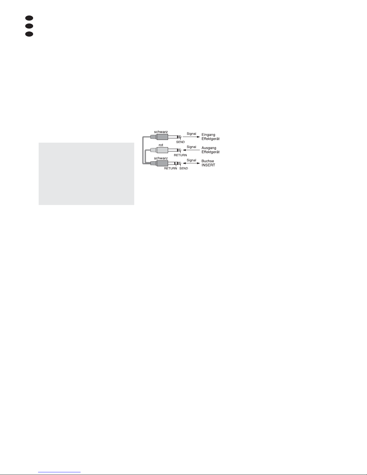
Das Effektgerät an die 6,3-mm-Klinkenbuch se
INSERT (13) des jeweiligen Kanals anschließen.
Die Stecker müssen wie folgt angeschlossen sein:
Spitze = Send (Ausgang)
Ring = Return (Eingang)
Schaft = Masse
Zum Anschluss von Effektgeräten mit getrennten Ein- und Ausgangsbuchsen werden Y-Kabel
benötigt, z. B. MCA-202 von MONACOR:
Abb. 7 Anschluss über das Y-Kabel MCA-202
4.2.2 Ausspielwege verwenden
Über die Ausspielwege AUX 1 –4 können Signalanteile aus den Eingangskanälen ausgekoppelt,
über Effektgeräte (z. B. Hallgeräte) bearbeitet und
über die Return-Eingänge wieder in das Mischpult
zurückgeführt werden. Der Signal abgriff für einen
als Effektweg genutzten Ausspielweg ist üblicherweise post-fader, d. h. das Kanalsignal wird nach
dem Fader (1) auf den Ausspielweg gemischt. Auf
diese Weise ist der Effektanteil eines Kanals
immer proportional zum eingestellten Kanalpegel.
Die Ausspielwege AUX 1 und AUX 2 sind für
jeden Kanal mit dem Schalter PRE / POST (8)
umschaltbar zwischen post-fader und pre-fader.
Die Ausspielwege AUX 3 und AUX 4 sind fest auf
post-fader eingestellt und dienen gleichzeitig als
Effektwege für die internen Effektprozessoren.
1) Je nachdem welcher Ausspielweg genutzt
wird, den Eingang des Effektgerätes an den
zugehörigen Mono-Ausgang AUX SENDS 1,
2, 3 oder 4 (38) anschließen.
2) Das vom Effektgerät kommende Signal auf
einen der Eingänge AUX RETURN (28) zu rückführen.
Hinweis: Beim Anschluss eines Mono-Geräts nur
die Buchse LEFT (MONO) verwenden. Das Signal
wird dann intern auf den rechten und linken Kanal
ge leitet.
3) Alternativ kann das Signal vom Effektgerät
auch auf den Line-Eingang eines freien Eingangskanals CH 1 – 16 gegeben werden.
Tipp: Soll ein Effektsignal auch auf einen Ausspielweg gemischt werden, muss unbedingt ein freier
Eingangskanal benutzt werden, weil dieses nur mit
den Reglern AUX 1 – 4 (7, 9) erfolgen kann.
4.3 Aufnahmegerät
Ein Aufnahmegerät kann an die Buchsen AUX
IN / TAPE IN und TAPE OUT (29) angeschlossen
werden (L = linker Kanal, R = rechter Kanal):
1) Für Aufnahmen den Eingang des Gerätes an
die Cinch-Buchsen TAPE OUT anschließen.
Hier liegt das mit dem Fader MAIN MIX (39)
eingestellte Summensignal an.
2)
Soll die Aufnahme über das Mischpult abgehört
werden (Kap. 5.7), den Ausgang des Gerätes
an die Cinch-Buchsen TAPE IN oder an die
3,5-mm-Klinkenbuchse AUX IN anschließen.
4.4 Regie-Monitoranlage oder
Kopfhörer anschließen
Über einen Kopfhörer oder eine Regie-Monitoranlage lassen sich folgende Signale abhören:
– die Signale der einzelnen Eingangskanäle
– das Stereo-Summensignal
– das Mono-Summensignal
– die Eingangssignale der Buchsen AUX RE -
TURN 1 und 2 (38)
– das Signal der Eingänge AUX IN / TAPE IN (29)
Den Kopfhörer (Mindestimpedanz 8 Ω) oder die
Regie-Monitoranalage an die Buchse PHONES /
CTRL-ROOM (51) anschließen.
4.5 Monitoranlage für die Musiker
Beim Einsatz einer Monitoranlage für die Bühnenbeschallung lassen sich die Ausspielwege
AUX 1 und AUX 2 als Monitorwege nutzen, so
dass die Musiker speziell für sie abgemischte
Musiksignale erhalten.
Die Signale für die Monitoranlage können an
den Buchsen AUX SENDS 1 und 2 (38) abgenommen werden. Alternativ kann auch ein Kanal
der internen Endstufe das Signal AUX 1 für die
Monitorlautsprecher verstärken und der andere
Kanal das Signal AUX 2. Dazu den Zuordnungsschalter (37) in die mittlere Position schieben.
Zum Anschluss der Lautsprecher siehe Kap. 4.7.
4.6 Zusätzliche Verstärker
für das Summensignal
Für die Beschallung des Publikums kann die
interne Endstufe verwendet werden. Reicht
diese nicht aus oder wird die Endstufe für die
Bühnenbeschallung genutzt oder soll das Summensignal z. B. in einem weiteren Raum zu
hören sein, einen zusätzlichen Verstärker an
den Ausgang MAIN MIX OUT (53) anschließen.
Hier liegt das mit dem Fader MAIN MIX (39) eingestellte Stereo-Summensignal an. Alternativ
oder zusätzlich können hierfür auch die CinchBuchsen TAPE OUT (29) verwendet werden.
Reicht auch eine monofone Beschallung
aus, kann auch der Ausgang MONO (52) genutzt
werden. Hier liegt das mit dem Fader MONO
(30) eingestellte Mono-Summensignal an. Die
interne Endstufe lässt sich ebenfalls zur mono fonen Beschallung nutzen (siehe Kap. 4.7).
4.7 Lautsprecher
Für den Anschluss der Lautsprecher können die
Klinkenbuchsen (57) oder die SPEAKON
®
-kompatiblen Buchsen (58) verwendet werden. Werden die SPEAKON®-kompatiblen Buchsen ge nutzt, den jeweiligen Lautsprecherstecker nach
dem Einstecken in die Buchse nach rechts drehen, bis er einrastet. Zum späteren Herausziehen den Sicherungsriegel am Stecker zurückziehen und den Stecker nach links drehen.
Der korrekte Anschluss der Lautsprecher
richtet sich nach der gewünschten Betriebsart
für die Endstufe, die mit dem Schiebeschalter
(37) eingestellt wird:
Stereobetrieb (obere Schalterposition)
Die Endstufe verstärkt das Stereo-Summensignal. Die Lautsprecher (Impedanz min. 4 Ω) an
die Buchse A (linker Kanal) und an die Buchse B
(rechter Kanal) anschließen.
2-Kanal-Betrieb (mittlere Schalterposition)
Die Endstufe verstärkt im Kanal A das Signal
des Ausspielwegs AUX 1 und im Kanal B das
Signal des Ausspielwegs AUX 2. Den Lautsprecher (Impedanz min. 4 Ω) für das Signal AUX 1
an die Buchse A anschließen und den Lautsprecher (Impedanz min. 4 Ω) für das Signal AUX 2
an die Buchse B.
Brückenbetrieb (untere Schalterposition)
Die Endstufe verstärkt das Mono-Summensignal
Vorsicht: Bei eingeschalteter Phantomspeisung darf kein Mikrofon mit asymmetrischem
Ausgang angeschlossen sein, da dieses be schädigt werden kann.
Um Schaltgeräusche in den Lautsprechern und
im Kopfhörer zu vermeiden, die Phantomspeisung nur ein- oder ausschalten, wenn das
Mischpult ausgeschaltet ist oder die zugehörigen Tasten MUTE (4) hineingedrückt sind und
der Regler PHONES / CTRL-ROOM (42) zugedreht ist.
7
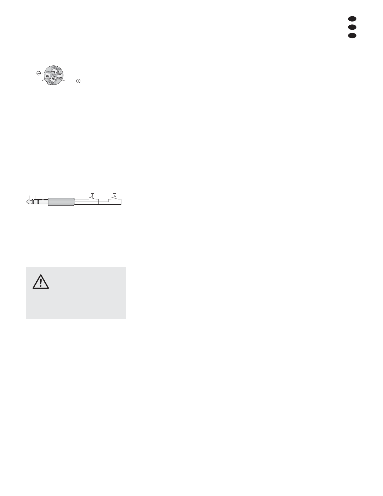
und gibt ihre gesamte Leistung an einen Lautsprecher ab. Der Lautsprecher (Impedanz min.
8Ω!) oder eine Lautsprechergruppe mit einer
Gesamtimpedanz von 8 Ω kann nur an die
SPEAKON
®-
kompatible Buchse A wie folgt an -
geschlossen werden:
Kontakt 1+ für den Pluspol
Kontakt 2+ für den Minuspol
Abb. 8 SPEAKON®-kompatibler Stecker
Anschluss für den Brückenbetrieb
4.8 Pultleuchte
Um das Mischpult zu beleuchten, lässt sich in
die XLR-Buchse LAMP (17) eine Schwanenhalsleuchte (12 V /500 mA max.) stecken, z. B. das
Modell GNL-304, GNL-305 oder GNL-314 von
„img Stage Line“. Die Leuchte wird zusammen
mit dem Mischpult ein- und ausgeschaltet.
4.9 Fußtaster für die Effektprozessoren
Um die internen Effektprozessoren FX 1 und FX 2
z. B. von der Bühne aus ein- und ausschalten zu
können, lassen sich zwei Fußtaster (z. B. FS-60
von MONACOR) an die dreipolige 6,3-mmKlinkenbuchse FOOT SW 1/ 2 (50) anschließen.
Abb. 9 Anschluss der Fußtaster
4.10 Stromversorgung
Das Mischpult über die Netzbuchse (54) mit
dem beiliegenden Netzkabel an eine Steckdose
(230 V~ / 50 Hz) anschließen.
5 Bedienung
5.1 Ein- und Ausschalten
1) Um Einschaltgeräusche und eine zu hohe
Lautstärke zu vermeiden, vor der Inbetriebnahme folgende Ausgangsregler auf Minimum stellen:
– MONO (30)
– MAIN MIX (39)
– PHONES / CRTL-ROOM (42)
– AUX 1 und 2 (33), wenn die Ausspielwege
1 und 2 als Monitorwege genutzt werden.
2) Je nachdem welcher Mikrofontyp angeschlossen ist, die 48-V-Phantomspeisung mit
den Schaltern PHANTOM (18) entweder einoder ausschalten (
Kapitel 4.1.1).
3) Wird die interne Endstufe verwendet, die korrekte Stellung des Betriebsartenschalters
(37) überprüfen (
Kapitel 4.7) und die Endstufe mit dem Schalter POWER AMP (36)
einschalten. Wird die Endstufe nicht verwendet, die Endstufe ausschalten.
4) Zum Ein- und Ausschalten des Mischpults
den Netzschalter POWER (56) betätigen. Bei
eingeschaltetem Gerät leuchten die Betriebsanzeige POWER (48) und die Displays (27).
5.2 Aussteuerung der Eingangskanäle
Die folgenden Bedienschritte dienen nur als
Hilfestellung, es sind auch andere Vorgehensweisen möglich.
1) Zuerst folgende Grundeinstellung vornehmen.
a) Alle Tasten LOW CUT (11) ausrasten.
b) Alle Regler TRIM (12), alle Klangregler
EQ (10) und alle Schieberegler des Equalizers (35) in die Mittelposition stellen.
c) Alle Regler AUX 1 bis AUX 4 (7, 9) für die
Ausspielwege ganz zudrehen.
d) Alle Panoramaregler PAN (5) und alle
Balanceregler BAL (6) in die Mitte drehen.
e) Alle Tasten MUTE (4, 22, 46), PFL (3, 21),
AFL (31, 44) und die Taste COMP/ LIM (40)
ausrasten.
f) Alle Kanalfader (1) sowie die Fader AUX
RTN 1 und 2 (19), MONO (30) und MAIN
MIX (39) zuziehen.
g) Die folgende Regler zudrehen:
– FX 1 TO MAIN, FX 2 TO MAIN (23)
– FX 1 TO AUX 1, FX 2 TO AUX 2 (24)
– AUX 1 bis AUX 4 (33) im Ausgangsfeld
– 2-TRACK IN (34)
2) Auf den ersten verwendeten Kanal ein Tonsignal geben (z. B. in ein Mikrofon singen, ein
Instrument spielen).
3) Soll das Signal über die angeschlossenen
Lautsprecher zu hören sein, den Fader (1)
des Kanals bis zur Position „0 dB“ aufziehen
und den Fader MONO (30) oder MAIN MIX
(39) so weit aufziehen, dass das Signal gut
zu hören ist. Das Signal lässt sich aber auch
bei zugezogenen Fadern über einen Kopfhörer oder eine Regie-Monitoranlage abhören,
Kap. 5.7.
4) Die Taste PFL (3) des Kanals drücken. Damit
ist die Vorhörfunktion für den Kanal eingeschaltet; zur Kontrolle leuchtet die LED
neben der Taste.
5) Die Taste AFL / PFL – MAIN (43) hineindrücken, damit die Pegelanzeige (45) das Kanalsignal anzeigt. Das Signal wird vor dem
Fader (1) und dem Regler PAN (5) bzw. BAL
(6) und der Taste MUTE (4) angezeigt.
6) Anhand der Pegelanzeige die Eingangsverstärkung mit dem Regler TRIM optimal einstellen, sodass ein Pegel im Bereich um 0 dB
angezeigt wird.
7) Den Klang mit den Reglern EQ (10) einstellen:
LOW für die Bässe: ±15 dB bei 80 Hz
MID FREQ
1
zum Einstellen der Filterfre-
quenz (100 Hz – 8 kHz) im Mittenbereich
MID
1
für die Mitten:
±15 dB bei 100 Hz–8kHz
MID LOW
2
für die unteren Mitten:
±15 dB bei 500 Hz
HI-MID
2
für die oberen Mitten:
±15 dB bei 3 kHz
HIGH für die Höhen: ±15 dB bei 12 kHz
1
nur bei den Monokanälen
2
nur bei den Stereokanälen
Bei Bedarf die Taste LOW CUT (11) zum
Unterdrücken tieffrequenter Störgeräusche
(z. B. Trittschall, Brummen) drücken.
Anschließend die Aussteuerung des Ka nals überprüfen und ggf. die Eingangsverstärkung mit dem Regler TRIM korrigieren.
8) Die Taste PLF wieder ausrasten, um die Vorhörfunktion für den Kanal auszuschalten. Die
Aussteuerung des Kanals lässt sich aber weiterhin mit der LED PEAK (2) grob kontrollieren. Leuchtet sie auf, wird der Kanal übersteuert. Dann die Eingangsverstärkung mit
dem Regler TRIM reduzieren.
9) Damit bei der Wiedergabe des Signals über
die Lautsprecher immer nur der Kanal zu
hören ist, der gerade eingestellt wird, nach der
Aussteuerung eines Kanals seinen Fader (1)
zurück auf Minimum stellen oder zum Stummschalten seine Taste MUTE (4) drücken.
10) Für alle weiteren Eingangskanäle die Bedienschritte 2) bis 9) wiederholen.
5.3 Eingangssignale mischen
1) Den Fader MONO (30) oder MAIN MIX (39)
so weit aufziehen, dass das Mischen der Eingangssignale gut über die Lautsprecher zu
hören ist. Das Mischsignal lässt sich aber
auch über einen Kopfhörer oder eine RegieMonitoranlage abhören,
Kap. 5.7.
2) Die Signale der Eingangskanäle mit den
Fadern (1) im gewünschten Lautstärkeverhältnis mischen. Die Fader nicht benutzter
Kanäle immer ganz zuziehen.
3) Für die Mono-Kanäle mit den Panoramareglern PAN (5) die Mono-Signale im StereoKlangbild platzieren und für die StereoKanäle mit den Reglern BAL (6) die Balance
der Stereo-Signale einstellen.
4) Zum Zumischen von Effekten siehe Kap. 5.6.
5) Das Eingangssignal der Buchsen AUX IN /
TAPE IN (29) lässt sich mit dem Regler
2-TRACK IN (34) auf die Signalsumme
mischen.
Hinweis: Wird während einer Aufnahme über die
Buchsen TAPE OUT das Aufnahmesignal als Eingangssignal auf die Buchsen AUX IN /TAPE IN ge geben, die Taste MUTE (46) hineindrücken, damit
keine Rückkopplung auftritt.
6) Die endgültige Lautstärke des Stereo-Summensignals mit dem Fader MAIN MIX einstellen und / oder die des Mono-Summensignals mit dem Fader MONO.
7) Die Summensignale können mit der Pegelanzeige (45) kontrolliert werden:
a) Für das Stereo-Summensignal die Taste
AFL / PFL – MAIN unter der Anzeige ausrasten.
b) Für das Mono-Summensignal die Taste
AFL / PFL – MAIN und die Taste AFL (31)
hineindrücken. Alle Tasten PFL (3, 21)
und die Taste AFL (44) im Bedienfeld
2-TRACK IN müssen ausgerastet sein.
Bei Übersteuerung leuchten die roten LEDs
CLIP auf; den Fader MAIN MIX bzw. MONO
dann entsprechend zurückziehen. Wird die
interne Endstufe genutzt, leuchten auch entsprechend die LEDs (49) auf:
SIG = Signalanzeige
CLIP = Übersteuerungsanzeige
PROT.= Die Schutzschaltung hat die End-
stufe abgeschaltet, z. B. bei Überhitzung oder bei einem Kurzschluss
an einer der Buchsen SPEAKERS
(57, 58).
8) Der Klang des Summensignals lässt sich mit
dem 7-Band-Equalizer an die Raumakustik
anpassen. Dazu den Equalizer mit der Taste
EQ ON (47) einschalten und den Klang mit
den Schiebereglern (35) einstellen.
Hinweis: Das Signal am Ausgang TAPE OUT (29)
wird ebenfalls durch den Equalizer beeinflusst. Bei
einer Aufnahme den Equalizer mit der Taste EQ ON
ggf. ausschalten.
9) Zum Stummschalten eines Kanals, z. B. während einer Spielpause, die zugehörige Taste
MUTE drücken.
TRS
FX1
T
S
FX2
R
1+ =2
-
1
-
2+ =
VORSICHT Stellen Sie die Lautstärke der
Lautsprecher und des Kopfhörers
nie sehr hoch ein. Hohe Lautstär-
ken können auf Dauer das Gehör
schädigen! Das Ohr gewöhnt sich an hohe
Lautstärken und empfindet sie nach einiger Zeit
als nicht mehr so hoch. Erhöhen Sie darum
eine hohe Lautstärke nach der Gewöhnung
nicht weiter.
D
A
CH
D
A
CH
8
5.4 Signalkompressor verwenden
Die Dynamik des Summensignals lässt sich
durch den integrierten Kompressor reduzieren.
Er schwächt den Pegel oberhalb einer einstellbaren Schwelle ab. Dies ist z. B. erforderlich,
wenn die Dynamik des Audiosignals größer ist
als das Aufnahme- oder Verstärkersystem
erlaubt oder eine geringe Dynamik (z. B. für Hintergrundmusik) erwünscht ist. Auch lassen sich
Signalspitzen ab schwächen, um eine höhere
Aussteuerbarkeit und damit eine höhere Durchschnittslautstärke zu erreichen.
1) Den Kompressor mit der Taste COMP/ LIM
(40) einschalten. Die LED neben der Taste
leuchtet.
2) Den Einsatzpunkt (Schwellwert) der Kompression mit dem Regler THRESHOLD (32)
einstellen. Das Kompressionsverhältnis mit
dem Regler RATIO (41) einstellen:
Position „4“:
Das Verhältnis beträgt 4 : 1; eine Eingangspegeländerung von 8 dB oberhalb des Thresh old-Wertes bewirkt eine Ausgangspegeländerung von 2 dB.
Position „∞“:
Der Kompressor arbeitet als Signalbegrenzer
(Limiter); das Ausgangssignal wird etwa auf
den mit dem Regler THRESHOLD eingestellten Wert begrenzt.
Tipp: Je höher der Schwellwert und je niedriger das
Kompressionsverhältnis eingestellt wird, desto
mehr bleibt die natürliche Dynamik erhalten.
3) Die LED neben dem Regler THRESHOLD
leuchtet auf, wenn das Eingangssignal des
Kompressors den eingestellten Schwellwert
überschreitet und das Ausgangssignal komprimiert wird. Die Pegelanzeige (45) kann
ebenfalls als Einstellhilfe dienen. Um den
Ausgangspegel ablesen zu können, die
Taste AFL / PFL – MAIN (43) unter der An zeige ausrasten.
Die Abbildung 10 zeigt als Beispiel den Ausgangspegel in Abhängigkeit vom Eingangspegel bei einem Schwellwert von
-
10 dB und
verschiedenen Kompressionsverhältnissen.
Abb. 10 Steuerkennlinien des Kompressors
bei einem Schwellwert von
-
10 dB
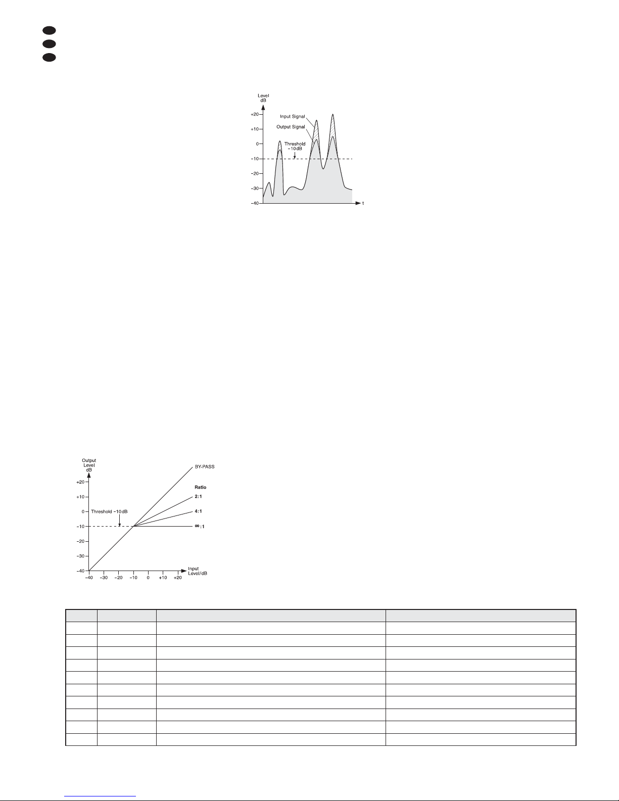
Die Abbildung 11 zeigt ein Eingangssignal
und das resultierende Ausgangssignal bei
einem Schwellwert von
-
10 dB und einem
Kompressionsverhältnis von 2 : 1. Unterhalb
des Schwellwertes bleibt das Signal unverändert und oberhalb wird es um den Faktor 2
komprimiert.
Abb. 11 Ein- und Ausgangssignal des Kompressors
bei einem Schwellwert von
-
10 dB und
einem Kompressionsverhältnis von 2 :1
5.5 Monitor-Ausspielwege einstellen
Beim Einsatz einer Monitoranlage für die Bühnenbeschallung lassen sich die Ausspielwege
AUX 1 und AUX 2 als Monitorwege nutzen.
1) In jedem Eingangskanal, dessen Signal für
die Bühnenbeschallung genutzt wird, den
Schalter PRE / POST (8) in die Position PRE
stellen.
2) Den Regler AUX 1 und / oder AUX 2 (33) für
die Lautstärke der Monitormischung so weit
aufdrehen, dass das Monitorsignal für die folgenden Einstellungen gut über die Monitoranlage zu hören ist.
3) Mit den Reglern AUX 1 und / oder AUX 2 (9) die
Kanalsignale auf die Monitorwege mischen:
Die Regler je nach gewünschtem Lautstärkeverhältnis der Kanäle aufdrehen. In den zu gehörigen Eingangskanälen muss die Taste
MUTE (4) ausgerastet sein.
4) Mit dem Regler FX 1 TO AUX 1 (24) lässt sich
das Effektsignal des internen Effektprozessors FX 1 (
Kap. 5.6.1) auf den Monitorweg AUX 1 mischen und mit dem Regler FX2
TO AUX 2 des Prozessors FX 2 auf den
Monitorweg AUX 2.
5) Die endgültige Lautstärke des Monitorsignals
mit dem Regler AUX 1 und / oder AUX 2 (33)
einstellen.
5.6 Effekte zumischen
5.6.1 Verwendung der internen
Effektprozessoren
Mit den zwei internen Effektprozessoren FX 1
und FX 2 lassen sich 100 verschiedene Effekte
erzeugen, die auf das Summensignal und auf
die Monitor-Ausspielwege AUX 1 und AUX 2 ge mischt werden können. Als Effektwege für die
Effektprozessoren dienen die Ausspielwege
AUX 3 und AUX 4. Im Folgenden wird die Einstellung des Effektwegs AUX 3 für den Prozessor FX 1 beschrieben, die Bedienung des Effektwegs AUX 4 für den Prozessor FX 2 ist identisch.
1) Damit die Effekteinstellungen zu hören sind,
die Regler FX 1 TO MAIN (23) und AUX 3
(33) vorerst ungefähr in die Mittelposition drehen.
2) Den Drehknopf PROGRAM (26) links- oder
rechtsherum drehen, bis die Nummer des
gewünschten Effekts (
Abb. 12 Effektübersicht) blinkend im Display (27) angezeigt
wird. Die Wahl durch Drücken des Knopfes
bestätigen: Die Nummer hört auf zu blinken,
der Effekt ist eingeschaltet.
3) Mit den Reglern AUX 3 (7) die Signale der
Eingangskanäle auf den Effektweg AUX 3
mischen. Mit diesen Reglern lässt sich für
jeden Kanal getrennt die gewünschte Effektintensität einstellen. Der Signalabgriff ist
nach dem Fader (1), d. h. der Effektanteil
eines Kanals ist immer proportional zum eingestellten Kanalpegel.
4) Die LED neben der Taste PEAK / MUTE (25)
dient bei eingeschaltetem Effektprozessor
als Übersteuerungsanzeige. Mit ihr lässt sich
die Aussteuerung grob kontrollieren. Leuchtet sie auf, den Regler AUX 3 (33) entsprechend zu rückdrehen.
5) Die Effektintensität für das Summensignal
mit dem Regler FX 1 TO MAIN einstellen.
6) Das Effektsignal lässt sich mit dem Regler
FX 1 TO AUX 1 (24) auch auf den Ausspielweg AUX 1 mischen.
7) Der Effektprozessor lässt sich mit einem an
der Buchse FOOT-SW 1/ 2 (50) angeschlossenen Fußtaster (Kap. 4.9) und mit der Taste
PEAK / MUTE (25) aus- und wieder einschalten (die Taste rastet nicht ein). Ist er ausgeschaltet, leuchtet zur Kontrolle die LED
neben der Taste PEAK / MUTE.
Nummer Name Effekt Parameter
00 – 09 Vocal Nachhalleffekt, besonders für Gesangsanwendungen geeignet Abklingzeit 0,8 – 0,9 s, Pre-Delay-Zeit 10 – 45 ms
10 – 19 Small Room Nachhalleffekt: Simulation eines kleinen bis mittelgroßen Raums Abklingzeit 0,7 – 2,1 s, Pre-Delay-Zeit 20 – 45 ms
20 – 29 Large Hall Nachhalleffekt: Simulation eines großen Saals Abklingzeit 3,6 – 5,4 s, Pre-Delay-Zeit 23 – 55 ms
30 – 39 Echo Echo-Effekt Delay-Zeit 145 – 205 ms
40 – 49 Echo + Verb Kombination von Echo-Effekt und Nachhalleffekt Delay-Zeit 208 – 650 ms, Abklingzeit 1,7 – 2,7s
50 – 59 Flange + Verb Kombination von Flanger-Effekt und Nachhalleffekt Geschwindigkeit 0,8 – 2,52Hz, Abklingzeit 1,5 – 2,9 ms
60 – 69 Plate Simulation einer klassischen, hell klingenden Hallplatte Abklingzeit 0,9 – 3,6s
70 – 79 Chorus + GTR Gitarreneffekt: Chorus Geschwindigkeit 0,92 – 1,72Hz
80 – 89 Rotary + GTR Gitarreneffekt: Rotary (Leslie-Effekt) Modulationstiefe 20 – 80%
90 – 99 Tremolo + GTR Gitarreneffekt: Tremolo Geschwindigkeit 0,6 – 5Hz
Abb. 12 Effektübersicht

9
D
A
CH
5.6.2 Externe Effektgeräte
Externe Effektgeräte können sowohl über die
Buchsen INSERT (13) in die Eingangskanäle
eingeschleift als auch an den Ausspielwegen
AUX 1 – 4 angeschlossen sein. Bei den über die
INSERT-Buchsen angeschlossenen Geräten
sind am Mischpult keine weiteren Einstellungen
möglich. Wichtig ist jedoch, dass die Geräte korrekt angeschlossen, eingeschaltet und richtig
eingestellt sind. Anderenfalls ist in dem zugehörigen Eingangskanal der Signalweg unterbrochen und das Kanalsignal kann weder abgehört
noch auf das Summensignal gemischt werden.
Für die an den Ausspielwegen AUX 1 – 4
angeschlossenen Geräte jeweils folgende Einstellungen vornehmen:
1) Damit die nachfolgenden Effekteinstellungen
zu hören sind, den zugehörigen Ausgangsund Eingangsregler vorerst ungefähr in die
Mittelposition stellen:
entsprechend dem verwendeten Ausspielweg
den zugehörigen Regler AUX 1, 2, 3 oder
4 (33)
entsprechend dem verwendeten Eingang
den Fader AUX RTN 1 oder 2 (19)
oder
den Fader (1) des zugehörigen Eingangskanals
2) Am Effektgerät den gewünschten Effekt ein-
schalten und als Ausgangssignal das reine
Effektsignal einstellen.
3) Je nachdem welcher Ausspielweg als Effekt-
weg genutzt wird, mit dem Regler AUX 1, 2, 3
oder 4 (7, 9) die Kanalsignale auf den Effektweg mischen. Mit diesen Reglern lässt sich
für jeden Kanal getrennt die gewünschte
Effektintensität ein stellen.
Werden die Ausspielwege 1 und 2 als Ef fektweg genutzt, müssen zuvor die Schalter
PRE/ POST (8) in die Position POST geschoben werden. Damit ist der Signalabgriff wie
bei den Wegen 3 und 4 nach dem Fader (1),
d. h. der Effektanteil eines Kanals ist immer
proportional zum eingestellten Kanalpegel.
Hinweise
1. Ist der Ausgang des Effektgeräts am Line-Ein-
gang eines Eingangskanals angeschlossen, den
entsprechenden Regler AUX … (7, 9) des Kanals
ganz zudrehen, sonst tritt eine Rückkopplung
auf: Wird z. B. der Ausspielweg 3 für das Effektgerät benutzt, den Regler AUX 3 zudrehen!
2. Die Signale der Effektwege 3 und 4 werden auch
auf die Eingänge der internen Effektprozessoren
gegeben (
Kap. 5.6.1). Deshalb je nach
Bedarf die Intensität der internen Effekte separat
mit den Reglern FX… TO MAIN (23) einstellen
oder die internen Effekte mit den Tasten MUTE
(25) stummschalten.
4) Mit den Reglern AUX … (33) den Pegel des
Gesamtsignal eines Ausspielweges so einstellen, dass das Effektgerät nicht übersteuert wird.
5) Das vom Effektgerät kommende Signal mit
dem jeweiligen Eingangsregler zumischen;
mit ihm lässt sich die Effektintensität für alle
Kanäle gemeinsam einstellen:
— Ist das Effektgerät am Eingang AUX RE -
TURN 1 oder 2 (28) angeschlossen, das
Effektsignal mit dem Fader AUX RTN 1
bzw. 2 (19) auf das Summensignal
mischen.
— Ist das Effektgerät am Line-Eingang (14,
15) eines Eingangskanals angeschlossen,
das Effektsignal mit dem entsprechenden
Kanalfader (1) auf das Summensignal
mischen. Zusätzlich kann das Effektsignal
mit dem Regler AUX 1 und / oder AUX 2 (9)
auf den Ausspielweg 1 und / oder 2 ge mischt werden (z. B. wenn diese als Monitorwege genutzt werden).
6) Um das Effektsignal zeitweise stummzuschalten, die Taste MUTE (4, 22) des Kanals
drücken, an dessen Eingang das Effektgerät
angeschlossen ist.
5.7 Abhören über einen Kopfhörer
oder eine Regie-Monitoranlage
Folgende Signale lassen sich über einen Kopfhörer oder eine Regie-Monitoranlage an der
Buchse PHONES / CTRL-ROOM (51) abhören:
1. Das Stereo-Summensignal post-fader, d.h.
nach dem Fader MAIN MIX (39)
Die Taste AFL / PFL – MAIN (43) unter der
Pegelanzeige ausrasten. Die LED neben der
Taste darf nicht leuchten.
2. Die Signale der einzelnen Eingangskanäle
pre-fader, d. h. vor dem Kanalfader (1), der
Taste MUTE (4) und dem Regler PAN (5)
oder BAL (6)
Die Taste PFL (3) des gewünschten Kanals
hineindrücken. Zur Kontrolle leuchtet die LED
neben der Taste. Zusätzlich die Taste AFL /
PFL – MAIN (43) unter der Pegelanzeige
hineindrücken. Die LED neben der Taste
leuchtet.
3. Das Mono-Summensignal post-fader, d. h.
nach dem Fader MONO (30)
Die Taste AFL (31) über dem Fader MONO
hineindrücken. Zusätzlich die Taste AFL / PFL
– MAIN (43) unter der Pegelanzeige hineindrücken.
4. Die Eingangssignale der Buchsen AUX
RETURN 1 und 2 (28) pre-fader, d. h. vor
den Fadern AUX RTN 1 und 2 (19)
Die Taste PFL (21) über dem Fader AUX
RTN 1 bzw. 2 hineindrücken. Zusätzlich die
Taste AFL / PFL – MAIN (43) unter der Pegelanzeige hineindrücken.
5. Das Eingangssignal der Buchsen AUX IN /
TAPE IN (29) post-fader, d. h. nach dem
Regler 2-TRACK IN (34)
Die Taste AFL (44) unter dem Regler
2-TRACK IN (34) hineindrücken. Zusätzlich
die Taste AFL / PFL – MAIN (43) unter der
Pegelanzeige hineindrücken. Den Regler
2-TRACK IN aufdrehen, damit das Signal zu
hören ist. Soll das Eingangssignal dabei nicht
auf das Summensignal gelangen, zuvor die
Taste MUTE (46) drücken.
Hinweise
1. Die Pegelanzeige (45) zeigt immer das Signal an,
welches zum Abhören ausgewählt ist.
2. Die Taste AFL / PFL – MAIN (43) unter der Pegelan-
zeige hat Vorrang vor den Tasten PFL (3, 21) und
den Tasten AFL (31, 44). Wenn die Taste AFL / PFL –
MAIN ausgerastet ist, wird stets das Stereo-Summensignal abgehört und angezeigt.
Die Tasten PFL und AFL sind dagegen untereinander gleichrangig. Sind einige dieser Tasten gleichzeitig hineingedrückt und ist auch die Taste AFL / PFL
– MAIN hineingedrückt, wird das Mischsignal der
zugehörigen Quellen abgehört und angezeigt.
6 Technische Daten
Blockschaltbild siehe Seite 61.
Ausgangsleistung
Sinusleistung
an 4-Ω-Lautsprecher:2 × 400W
an 8-Ω-Lautsprecher:2 × 300W
Brückenbetrieb: . . . . 1 × 700 W an 8Ω
Maximale Leistung: . . 2 × 600 W an 4 Ω
Eingänge
(Empfindlichkeit / Impedanz; Anschluss)
Mic: . . . . . . . . . . . . . . 0,5 mV/ 3 kΩ;
XLR, symmetrisch
Line (Mono-Kanal): . . 2 mV/10kΩ;
6,3-mm-Klinke, sym.
Line (Stereo-Kanal): . . 8 mV/10kΩ;
6,3-mm-Klinke, sym.
Tape In: . . . . . . . . . . . 60 mV/ 8 kΩ; Cinch,
3,5-mm-Klinke, asym.
Aux Return: . . . . . . . . 80 mV/10 kΩ;
6,3-mm-Klinke, sym.
Insert (Return): . . . . . . 80 mV/ 9 kΩ;
6,3-mm-Klinke, asym.
Ausgänge
(Pegel / Impedanz; Anschluss)
Main Mix Out, stereo: . 1,5 V (bei Anzeige
0 dB) /120 Ω;
XLR, sym. und
6,3-mm-Klinke, asym.
Mono Out: . . . . . . . . . 500 mV/120Ω;
6,3-mm-Klinke, asym.
Tape Out, stereo: . . . . 680 mV/1 kΩ; Cinch
Aux Sends, mono: . . . 10 V/120Ω;
6,3-mm-Klinke, asym.
Kopfhörerimpedanz: . . . ≥ 8 Ω
Frequenzbereich: . . . . . 20 – 20 000Hz
Klirrfaktor: . . . . . . . . . . . < 0,04 %
Störabstand: . . . . . . . . . 89 dB
Übersprechen: . . . . . . .
-
63 dB
Klangregler
Bässe: . . . . . . . . . . . . ±15 dB/80 Hz
Höhen: . . . . . . . . . . . . ±15 dB /12 kHz
Mitten Mono-Kanal: . . ±15 dB/ 100 – 8000 Hz
Mitten Stereo-Kanal: . ±15 dB/ 500Hz
±15 dB /3 kHz
Equalizer: . . . . . . . . . . . ±15 dB bei
63 / 160 / 400 Hz /
1/ 2,5 / 6,3 /16 kHz
Low-Cut-Filter: . . . . . . . 75 Hz /18 dB pro Okt.
Kompressor
Schwellwert
(Threshold)
:-40 dB bis +22 dB
Ratio: . . . . . . . . . . . . . 2 :1 bis ∞:1
Ansprechzeit
(Attack)
: .1ms
Rückstellzeit
(Release)
:2s
Phantomspeisung
für Mic 1 – 12: . . . . . . . . +48 V
Spannung für Pultleuchte: 12 V /500 mA
Netzspannung: . . . . . . . 230 V~/ 50 Hz
Leistungsaufnahme
im Leerlauf: . . . . . . . . 60 VA
bei maximaler
Ausgangsleistung: . . . 1250 VA
Einsatztemperatur: . . . . 0 – 40 °C
Maße (B × H × T): . . . . . 545 × 145 × 465 mm
Gewicht: . . . . . . . . . . . . 12,5 kg
6.1 Steckerbelegung
Lautsprecheranschlüsse
für den Stereo- oder 2-Kanalbetrieb
2-poliger 6,3-mm-Klinkenstecker
SPEAKON
®
-kompatibler Stecker
Lautsprecheranschluss an der Buchse „A“
für den Brückenbetrieb
SPEAKON
®
-kompatibler Stecker
Mikrofonanschlüsse
XLR-Stecker für symmetrischen Anschluss
Line-Signal-Anschlüsse
XLR-Kupplung für symmetrischen Anschluss
3-poliger 6,3-mm-Klinkenstecker
für symmetrischen Anschluss
2-poliger 6,3-mm-Klinkenstecker
für asymmetrischen Anschluss
6,3-mm-Stereo-Klinkenstecker
für Stereo-Signale (Phones / CTRL-Room)
3-poliger 3,5-mm-Klinkenstecker
für Stereosignale (Aux In)
3-poliger 6,3-mm-Klinkenstecker
für die INSERT-Buchsen
Anschluss für zwei Fußtaster
3-poliger 6,3-mm-Klinkenstecker
FX 1, FX 2 = Taster für die Effektprozessoren
FX 1 und FX 2
Anschluss für eine Pultleuchte
XLR-Stecker
Änderungen vorbehalten.
T = Pluspol
S = Minuspol
1+2
-
1
-
2+
1+ = Pluspol
1
-
= Minuspol
1 = Masse
2 = Signal +
3 = Signal
-
21
3
T = Send (Ausgang)
R = Return (Eingang)
S = Masse
TRS
FX1
T
S
FX2
R
1+ = Pluspol
2+ = Minuspol
1+2
-
1
-
2+
T = linker Kanal
R = rechter Kanal
S = Masse
1 = Minuspol 12 V
2 = Pluspol 12 V
3 = frei
1 = Masse
2 = Signal +
3 = Signal
-
T = linker Kanal
R = rechter Kanal
S = Masse
T = Signal
S = Masse
T = Signal +
R = Signal
-
S = Masse
D
A
CH
10
Diese Bedienungsanleitung ist urheberrechtlich für MONACOR
®
INTERNATIONAL GmbH & Co. KG
geschützt. Eine Reproduktion für eigene kommerzielle Zwecke – auch auszugsweise – ist untersagt.

11

All operating elements and connections de scribed can be found on the fold-out page 3.
Contents
1 Operating Elements
and Connections . . . . . . . . . . . . . . . . 12
1.1 Input channels . . . . . . . . . . . . . . . . . . . 12
1.2 Effect processors,
AUX RETURN and TAPE IN / OUT . . . . 12
1.3 Output panel . . . . . . . . . . . . . . . . . . . . . 13
1.4 Rear panel . . . . . . . . . . . . . . . . . . . . . . 13
2 Safety Notes . . . . . . . . . . . . . . . . . . . . 13
3 Applications . . . . . . . . . . . . . . . . . . . . 13
4 Connecting the Units . . . . . . . . . . . . . 14
4.1 Audio sources . . . . . . . . . . . . . . . . . . . . 14
4.1.1 Microphones . . . . . . . . . . . . . . . . . . . 14
4.1.2 Line audio sources . . . . . . . . . . . . . . 14
4.2 Effect units . . . . . . . . . . . . . . . . . . . . . . 14
4.2.1 Inserting effect units . . . . . . . . . . . . . 14
4.2.2 Using send ways . . . . . . . . . . . . . . . . 14
4.3 Recorder . . . . . . . . . . . . . . . . . . . . . . . . 14
4.4 Connecting a control monitor system
or headphones . . . . . . . . . . . . . . . . . . . 14
4.5 Monitor system for the musicians . . . . . 14
4.6 Additional amplifiers for the sum signal 14
4.7 Speaker systems . . . . . . . . . . . . . . . . . 14
4.8 Console light . . . . . . . . . . . . . . . . . . . . . 15
4.9 Foot pedal for the effect processors . . . 15
4.10 Power supply . . . . . . . . . . . . . . . . . . . . 15
5 Operation . . . . . . . . . . . . . . . . . . . . . . . 15
5.1 Switching on and off . . . . . . . . . . . . . . . 15
5.2 Level control of the input channels . . . . 15
5.3 Mixing input signals . . . . . . . . . . . . . . . 15
5.4 Using the signal compressor . . . . . . . . 16
5.5 Adjusting monitor send ways . . . . . . . . 16
5.6 Adding effects . . . . . . . . . . . . . . . . . . . . 16
5.6.1 Using internal effect processors . . . . 16
5.6.2 External effect units . . . . . . . . . . . . . . 17
5.7 Monitoring via headphones
or a control monitor system . . . . . . . . . 17
6 Specifications . . . . . . . . . . . . . . . . . . . 18
6.1 Plug configuration . . . . . . . . . . . . . . . . . 18
Block diagram . . . . . . . . . . . . . . . . . . . . 61
1 Operating Elements
and Connections
1.1 Input channels
Fig. 1 Mono input channel CH 3
All mono input channels (CH 1 … CH 12)
are identical.
Fig. 2 Stereo input channel CH 13/14
With the exception of the connection for
the console light (17), the second stereo
input channel (CH 15/16) is identical.
1 Channel fader to adjust the volume of the
channel and to fade in / fade out the channel
signal
2 LED PEAK lights up shortly when the maxi-
mum undistorted signal level has been
reached. If it lights up for a longer period of
time, the channel is overloaded. Then turn
back the control TRIM (12) accordingly.
3 Button PFL (with LED indicator) for pre-fader
listening to the corresponding channel via
headphones or a monitor system connected
to the jack PHONES / CTRL-ROOM (51). To
have the level indicators (45) indicate the
channel signal, make sure that the button
(43) beneath the indicators is pressed.
4 Button MUTE (with LED indicator) to mute
the channel
5 Panorama control PAN to place the mono
signal in the stereo sound
6 Balance control BAL for the stereo channels
7 Controls AUX 3 and AUX 4 to add the chan-
nel signal to the send ways AUX 3 and AUX 4
(post-fader)
The send ways AUX 3 and AUX 4 are used as
effect ways for the internal effect processors
and for the external effect units.
8 Selector switch PRE / POST for the send
ways AUX 1 and AUX 2
Position POST: signal is picked up post-fader
The channel signal is fed to the send way
after the fader (1).
Position PRE: signal is picked up pre-fader
The channel signal is fed to the send way
ahead of the fader.
9 Controls AUX 1 and AUX 2 to add the chan-
nel signal to the send ways AUX 1 and AUX 2
(switchable: pre-fader / post-fader)
The send ways AUX 1 and AUX 2 can be
used as monitor ways for on-stage monitoring by the musicians or as effect ways for
external effect units.
10 Equalizer control
LOW for the bass frequencies: ±15 dB at 80Hz
MID FREQ¹ to adjust the filter frequency
(100 Hz – 8 kHz) in the midrange
MID¹ for the mid-frequencies:
±15 dB at 100 Hz – 8 kHz
MID LOW² for the lower mid-frequencies:
±15 dB at 500 Hz
HI-MID² for the upper mid-frequencies:
±15 dB at 3 kHz
HIGH for the high frequencies:
±15 dB at 12 kHz
1
for mono channels only
2
for stereo channels only
11 Button LOW CUT for the high pass filter
When the button is pressed, unwanted signal
parts below 75 Hz will be suppressed (e. g.
impact noise)
12 Control TRIM to adjust the input amplification
13 Jack INSERT (6.3 mm jack) to insert effect
units (e. g. compressors) into the mono input
channels
Plug connections:
tip = Send (output)
ring = Return (input)
sleeve = Ground
14 Stereo input LINE IN (6.3 mm jacks, bal.) to
connect a signal source with line output level
(e. g. musical instrument, CD / MP3 player)
Note: When connecting a mono unit, only use the
jack LEFT (MONO). The signal will then be internally sent to the right and left channels.
15 Mono input LINE IN (6.3 mm jack, bal.) to
connect a signal source with line output level
16 Input MIC to connect a microphone (XLR
jack, bal.)
The phantom power supply can be switched
on for the microphone inputs,
item 18.
17 XLR jack LAMP to connect a gooseneck light
to illuminate the console (12 V /500 mA max.)
18 Switch PHANTOM (with LED indicator) to
switch on / off the 48 V phantom power supply
for four microphone inputs
Please observe the warning notes with
regard to the phantom power supply in chapter 4.1.1.
1.2 Effect processors,
AUX RETURN and TAPE IN/OUT
19 Faders AUX RTN 1 and 2 to add the signals
at the inputs AUX RETURN 1 and 2 (28) to
the sum signal
20 LED PEAK lights up shortly when the maxi-
mum undistorted signal level has been
reached. If it lights up for a longer period of
time, the channel is overloaded. Then close
the fader AUX RTN (19) accordingly.
21 Button PFL (with LED indicator) for pre-fader
listening to the corresponding RETURN input
via headphones or a monitor system connected to the jack PHONES / CTRL-ROOM
(51). To have the level indicators (45) indicate the RETURN signal, make sure that the
button (43) beneath the indicators is pressed.
22 Button MUTE (with LED indicator) to mute
the RETURN signal
23 Controls FX 1 TO MAIN and FX 2 TO MAIN to
add the internal effect signals to the sum signal
24 Controls FX 1 TO AUX 1 and FX 2 TO AUX 2
to add the internal effect signals to the send
ways AUX 1 and AUX 2
25 Buttons MUTE to mute the internal effect
processors
When the effect processor is muted, the LED
next to the button will light permanently as an
indication. When the effect processor is
switched on, the LED will indicate any overload of the processor that might occur.
26 Knobs PROGRAM to select the effect: Turn
the knob, until the effect number starts flashing on the display (27), then briefly press the
knob to confirm.
27 Displays to indicate the effect number se -
lected
28 Inputs AUX RETURN 1 and 2 (6.3 mm jacks,
bal.), can be used as inputs for effect units or
for additional line audio sources
12
GB

To add the input signals to the sum signal,
use the faders AUX RTN 1 and 2 (19).
Note: When connecting a mono unit, only use the
jack LEFT (MONO). The signal will then be internally sent to the right and left channels.
29 Input jacks and output jacks (RCA) for a
recorder; a 3.5 mm jack is also provided as
an input
The sum signal after the fader MAIN MIX (39)
is available at the jacks TAPE OUT.
To add the signal of the jacks AUX IN / TAPE
IN to the sum signal, use the control
2-TRACK IN (34).
1.3 Output panel
30 Fader MONO to adjust the level of the mono
sum signal at the jack MONO (52) and to
adjust the volume of the mono sum signal
when it is sent to the power amplifier [assignment switch (37) in the position MONO
BRIDGE]
31 Button AFL (with LED indicator) to monitor
the mono sum signal after the fader MONO
(30) via headphones or a monitor system
connected to the jack PHONES / CTRLROOM (51). To have the level indicators (45)
indicate the signal, make sure that the button
(43) beneath the indicators is pressed.
32 Control THRESHOLD to adjust the threshold
value; when this value is exceeded, the
stereo sum signal will be compressed
33 Level controls AUX 1 – 4 for the total signals
of the four send ways that are available at the
outputs AUX SENDS (38); the signals of the
send ways AUX 3 and 4 will also be sent to
the internal effect processors
34 Control 2-TRACK IN to add the signal of the
jacks AUX IN / TAPE IN (29) to the sum signal
35 7-band equalizer for the sum signal
36 Switch POWER AMP to switch on / off the
power amplifier
37 Switch to assign the operation mode to the
power amplifier
upper position = The power amplifier oper-
ates in stereo mode and amplifies the left
and the right sum signals.
mid position = The power amplifier operates
in 2-channel mode: In the channel A, it
amplifies the signal of the send way AUX 1;
in the channel B, it amplifies the signal of
the send way AUX 2
lower position = The power amplifier oper-
ates in bridged mode (double output power
at an 8 Ω speaker) and amplifies the mono
sum signal.
38 Outputs AUX SENDS 1 – 4 (6.3 mm jacks,
unbal.) for the four send ways
39 Fader MAIN MIX to adjust the level of the
stereo sum signal at the output MAIN MIX
OUT (53) and to adjust the volume of the
stereo sum signal when it is sent to the power
amplifier [assignment switch (37) in the position MAIN L / MAIN R]
40 Button COMP/ LIM (with LED indicator) to
switch on the compressor for the stereo sum
signal
41 Control RATIO to adjust the compression
ratio
42 Volume control PHONES / CTRL-ROOM for
the output PHONES / CTRL-ROOM (51)
43 Button AFL / PFL – MAIN (with LED indicator)
to select the signal that is to be indicated by
the level indicators (45) and to be sent to the
output PHONES / CTRL-ROOM (51)
Button disengaged:
The stereo sum signal after the fader MAIN
MIX (39) will be indicated and sent to the
output PHONES / CTRL-ROOM.
Button pressed:
The signal of a channel whose button PFL
(3, 21) or AFL (31, 44) is pressed will be
indicated and sent to the output PHONES /
CTRL-ROOM.
44 Button AFL (with LED indicator) to monitor
the signal of the jacks AUX IN /TAPE IN (29)
after the control 2-TRACK IN (34) via headphones or a monitor system connected to the
jack PHONES / CTRL-ROOM (51). To have
the level indicators (45) indicate the signal,
make sure that the button (43) beneath the
indicators is pressed.
45 Level indicators; indicate the level of the sig-
nal that has been selected to be monitored by
means of the output PHONES / CTRL-ROOM
(51), see item 43
46 Button MUTE (with LED indicator) to mute
the signal at the input AUX IN / TAPE IN (29)
47 Button EQ ON (with LED indicator) to switch
on the equalizer for the sum signal
48 LED POWER
49 LED indicators A (for the left channel of the
power amplifier) and B (for the right channel
of the power amplifier)
SIG = Signal indication
CLIP = Overload indication
PROT.= The protective circuit has switched
off the power amplifier, e. g. in case
of overheating or in case of short circuit at one of the jacks SPEAKERS
(57, 58).
50 Connection FOOT-SW 1/ 2 (6.3 mm jack, 3
poles) for two foot pedals to switch on / off the
internal effect processors (connection see
chapter 4.9)
51 Output PHONES / CTRL-ROOM (6.3 mm jack,
unbal.) to connect stereo headphones (minimum impedance: 8 Ω) or a control monitor
system
52 Line output MONO (6.3 mm jack, unbal.) for
the mono sum signal
53 Line output MAIN MIX OUT for the stereo sum
signal (XLR, bal. and 6.3 mm jacks, unbal.)
1.4 Rear panel
54 Mains jack for connection to a mains socket
(230 V~ / 50 Hz) via the mains cable supplied
55 Support for the mains fuse
Always replace a blown fuse by a fuse of the
same type.
56 POWER switch
57 Speaker jacks (6.3 mm jacks)
alternative to the jacks (58)
58 Speaker jacks (SPEAKON
®
compatible)
alternative to the 6.3 mm jacks (57)
2 Safety Notes
The unit corresponds to all relevant directives of
the EU and is therefore marked with
.
Please observe the following items in any case:
G
The unit is suitable for indoor use only. Protect
it against dripping water and splash water,
high air humidity and heat (admissible ambient
temperature range: 0 – 40 °C).
G
Do not place any vessel filled with liquid on the
unit, e. g. a drinking glass.
G
The heat generated inside the unit must be
dissipated by air circulation; never cover the
air vents of the housing.
G
Do not operate the unit and immediately disconnect the mains plug from the socket
1. if the unit or the mains cable is visibly damaged,
2. if a defect might have occurred after the unit
was dropped or suffered a similar accident,
3. if malfunctions occur.
In any case the unit must be repaired by skilled
personnel.
G
Never pull the mains cable to disconnect the
mains plug from the socket; always seize the
plug.
G
For cleaning only use a dry, soft cloth; never
use water or chemicals.
G
No guarantee claims for the unit and no liability for any resulting personal damage or material damage will be accepted if the unit is used
for other purposes than originally intended, if it
is not correctly connected or operated, or if it is
not repaired in an expert way.
3 Applications
This audio mixer with integrated stereo power
amplifier (class D, 2 × 400 W
RMS at 4 Ω speak-
ers) is suited for various PA and recording applications. It is designed as a table-top unit and
provides 12 mono input channels and 2 stereo
input channels for connecting microphones (also
phantom-powered) and audio sources with line
output level (e. g. instruments, players).
The input signals can be added to a stereo
sum channel, a mono sum channel and four
send ways. Two digital effect processors are
available for adding effects. Headphones or a
monitor system may be connected for monitoring the audio mix or for pre-fader listening to individual channel signals.
If the unit is to be put out of operation
definitively, take it to a local recycling
plant for a disposal which is not harmful
to the environment.
WARNING The unit uses dangerous mains
voltage. Leave servicing to skilled
personnel only and do not insert
anything into the air vents! Inexpert handling of the unit may result
in electric shock.
13
GB

4 Connecting the Units
To avoid interfering noise, switch off the mixer or
close the appropriate faders / set the appropriate
controls to minimum in the corresponding channels prior to connecting / disconnecting.
4.1 Audio sources
In the mono input channels, it is not possible to
switch between the microphone input (16) and
the line input (15). Therefore, only connect one
of these two inputs per channel.
4.1.1 Microphones
Connect microphones to the balanced XLR
jacks MIC (16). For phantom-powered microphones, the switches PHANTOM (18) are available: With each of these switches, a phantom
power supply of 48 V for four microphone inputs
can be switched on. When a phantom power
supply is switched on, the LED next to the corresponding switch will light up.
4.1.2 Line audio sources
Connect audio sources with line signal level
(e. g. receivers of wireless microphone systems,
effect units, instruments, players) to the 6.3 mm
jacks LINE IN (14, 15) of the input channels. The
jacks are balanced. To connect units with unbalanced output, use 2-pole 6.3 mm plugs.
— Connect mono units to the jacks (15) of the
mono channels CH 1 to CH 12. To connect a
mono unit to a stereo channel, only use the
upper jack LEFT (MONO); the mono signal
will then be internally sent to the right and left
channels.
— Connect stereo units to the jacks (14) of the
stereo channels CH 13/14 and CH 15/16.
It is also possible to connect stereo units to
two mono channels: For the mono channel to
which the left channel of the stereo unit is
connected, turn the control PAN (5) to the left
stop to the position “L”; for the mono channel
to which the right channel is connected, turn
the control PAN to the right stop to the position “R”.
The following stereo inputs can be used to connect additional line sources:
1. inputs AUX RETURN 1 and 2 (28)
To connect a mono unit, only use the jack
LEFT (MONO); the mono signal will then be
internally sent to the right and left channels.
2. input AUX IN/TAPE IN (29)
e. g. to connect a CD player for background
music during intervals
4.2 Effect units
4.2.1 Inserting effect units
Effect units (e. g. units for audio processing such
as compressors, equalizers and noise gates)
may be directly inserted into the mono channels:
The channel signal is decoupled after the control
TRIM (12) and the low cut filter (11), is routed via
the effect unit and is then returned to the channel at the same position in the signal way.
Connect the effect unit to the 6.3 mm jack
INSERT (13) of the respective channel. The
plugs must be connected as follows:
tip = Send (output)
ring = Return (input)
sleeve = Ground
To connect effect units with separate input and
output jacks, Y cables are required, e. g. MCA202 from MONACOR:
Fig. 7 Connection via Y cable MCA-202
4.2.2 Using send ways
Via the send ways AUX 1 – 4, signal parts can be
decoupled from the input channels, processed
by means of effect units (e. g. reverb units) and
returned to the mixer via the Return inputs. Normally, the signal for a send way used as an effect
way is picked up post-fader, i. e. the channel signal is added to the send way after the fader (1).
Thus, the effect part of a channel is always in
proportion to the channel level adjusted.
For each channel, the switch PRE / POST (8)
can be used to switch the send ways AUX 1 and
AUX 2 over between post-fader and pre-fader.
The send ways AUX 3 and AUX 4 are preset to
post-fader; this cannot be changed. The send
ways AUX 3 and AUX 4 also serve as effect
ways for the internal effect processors.
1) Depending on the send way used, connect
the input of the effect unit to the correspond ing mono output AUX SENDS 1, 2, 3 or 4
(38).
2) Return the signal coming from the effect unit
to one of the inputs AUX RETURN (28).
Note: To connect a mono unit, only use the jack
LEFT (MONO); the signal will then be internally sent
to the right and left channels.
3) Alternatively, feed the signal from the effect
unit to the line input of an available input
channel CH 1 – 16.
Hint: For adding an effect signal to a send way, an
unused input channel must be available, because
this addition can only be carried out with the controls AUX 1 – 4 (7, 9).
4.3 Recorder
A recorder can be connected to the jacks AUX
IN/ TAPE IN and TAPE OUT (29) [L= left channel, R = right channel]:
1) For recording, connect the input of the
recorder to the RCA jacks TAPE OUT. At
these jacks, the sum signal adjusted by
means of the fader MAIN MIX (39) is available.
2) For monitoring the recording via the mixer
(chapter 5.7), connect the output of the
recorder to the RCA jacks TAPE IN or to the
3.5 mm jack AUX IN.
4.4 Connecting a control monitor
system or headphones
The following signals can be monitored via headphones or via a control monitor system:
– the signals of the individual input channels
– the stereo sum signal
– the mono sum signal
– the input signals of the jacks AUX RETURN 1
and 2 (38)
– the signals of the inputs AUX IN /TAPE IN (29)
Connect the headphones (minimum impedance:
8 Ω) or the control monitor system to the jack
PHONES / CTRL-ROOM (51).
4.5 Monitor system for the musicians
When a monitor system is used for stage PA
applications, the send ways AUX 1 and AUX 2
can be used as monitor ways to provide the
musicians with music signals that have been
especially mixed for them.
The signals for the monitor system can be
picked up at the jacks AUX SENDS 1 and 2 (38).
Alternatively, one channel of the internal power
amplifier can amplify the signal AUX 1 for the
monitor speakers and the other channel can
amplify the signal AUX 2: Set the assignment
switch (37) to mid-position. Please refer to chapter 4.7 for information on how to connect the
speaker systems.
4.6 Additional amplifiers
for the sum signal
The internal power amplifier can be used to produce the sound for the audience. If the internal
power amplifier does not suffice or if it is used to
provide the musicians with sound for on-stage
monitoring or if the sum signal shall be audible in
an additional room, connect an additional amplifier to the output MAIN MIX OUT (53). At this output, the sum signal adjusted by means of the
fader MAIN MIX (39) is available. The RCA jacks
TAPE OUT (29) can be used as an alternative or
in addition.
For monophonic PA applications, the output
MONO (52) can be used. At this output, the
mono sum signal adjusted by means of the fader
MONO (30) is available. The internal power
amplifier may be used for monophonic PA applications as well (see chapter 4.7).
4.7 Speaker systems
For connecting the speaker systems, the
speaker jacks (57) or the SPEAKON
®
compati-
ble jacks (58) are available. If the SPEAKON
®
compatible jacks are used, insert the appropriate
speaker plug into the jack and then turn the
plug clockwise until it engages. To remove the
speaker plug, retract the latch of the plug and
turn the plug counterclockwise.
The correct connection of the speaker systems depends on the desired operation mode for
the power amplifier. This mode is adjusted by
means of the assignment switch (37):
Stereo operation (switch in upper position)
The power amplifier amplifies the stereo sum
signal. Connect the speaker systems (minimum
impedance: 4 Ω) to the jack A (left channel) and
to the jack B (right channel).
2-channel operation (switch in mid-position)
In the channel A, the power amplifier amplifies the
signal of the send way AUX 1; in the channel B,
it amplifies the signal of the send way AUX 2.
Connect the speaker system (minimum impedance: 4 Ω) for the signal AUX 1 to the jack A, and
connect the speaker system (minimum impedance: 4 Ω) for the signal AUX 2 to the jack B.
Caution: When the phantom power supply is
switched on, do not connect any microphone
with unbalanced output; it may be damaged.
To prevent switching noise in the speakers and
the headphones, only switch the phantom
power supply on or off when the mixer has been
switched off or when the corresponding buttons
MUTE (4) have been pressed and the control
PHONES / CTRL-ROOM (42) has been set to
minimum.
14
GB
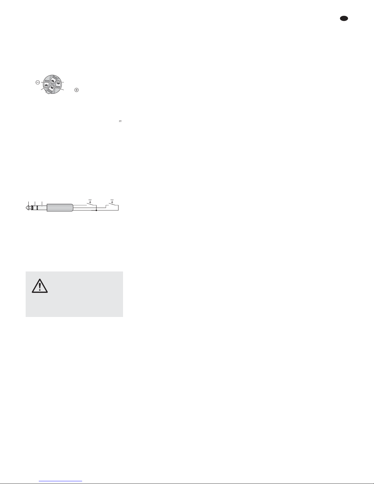
Bridged operation (switch in lower position)
The power amplifier amplifies the mono sum signal and provides its total power to a speaker system. The speaker system (minimum imped-
ance: 8 Ω!) or a speaker system group with a
total impedance of 8 Ω can only be connected
to the SPEAKON
®
compatible jack A in the fol-
lowing way:
Contact 1+ for the positive pole
Contact 2+ for the negative pole
Fig. 8 SPEAKON®compatible plug
Connection for bridged operation
4.8 Console light
To illuminate the mixer, a gooseneck light (12 V /
500 mA max.), e. g. model GNL-304, GNL-305
or GNL-314 from “img Stage Line”, can be connected to the XLR jack LAMP (17). The light is
switched on and off together with the mixer.
4.9 Foot pedal
for the effect processors
To be able to switch on / off the internal effect
processors FX 1 and FX 2 from the stage, for
example, two foot pedals (e. g. FS-60 from
MONACOR) can be connected to the 3-pole
6.3 mm jack FOOT SW 1/ 2 (50).
Fig. 9 Connection of the foot pedals
4.10 Power supply
Use the mains cable supplied to connect the
mains jack (54) of the mixer to a socket (230 V~/
50 Hz).
5 Operation
5.1 Switching on and off
1) To prevent switching noise and an excessive
volume, set the following output controls to
minimum prior to switching on the mixer:
– MONO (30)
– MAIN MIX (39)
– PHONES / CTRL-ROOM (42)
– AUX 1 and AUX 2 (33) when the send ways
1 and 2 are used as monitor ways.
2) Depending on the microphone type con-
nected, switch the 48 V phantom power supply on or off, using the switches PHANTOM
(18) [
chapter 4.1.1].
3) If the internal power amplifier is used, check
whether the assignment switch (37) has been
set to the correct position (
chapter 4.7)
and then switch on the power amplifier, using
the switch POWER AMP (36). If the power
amplifier is not used, switch it off.
4) To switch the mixer on and off, use the
POWER switch (56). When the mixer is
switched on, the LED POWER (48) and the
displays (27) light up.
5.2 Level control of the input channels
The following steps merely serve as an aid; other
procedures are possible.
1) First, make the following basic adjustment.
a) Disengage all buttons LOW CUT (11).
b) Set all controls TRIM (12), all equalizer
controls EQ (10) and all sliders of the
equalizer (35) to mid-position.
c) Set all controls AUX 1 to AUX 4 (7, 9) for
the send ways to minimum.
d) Set all panorama controls PAN (5) and all
balance controls BAL (6) to mid-position.
e) Disengage all buttons MUTE (4, 22, 46),
PFL (3, 21), AFL (31, 44) and the button
COMP/LIM (40).
f) Close all channels faders (1) and the
faders AUX RTN 1 and 2 (19), MONO (30)
and MAIN MIX (39).
g) Set the following controls to minimum:
– FX 1 TO MAIN, FX 2 TO MAIN (23)
– FX 1 TO AUX 1, FX 2 TO AUX 2 (24)
– AUX 1 to AUX 4 (33) on the output panel
– 2-TRACK IN (34)
2) Feed an audio signal to the channel first used
(e. g. sing into a microphone, play a musical
instrument).
3) If the signal is to be made audible via the
speaker systems connected, advance the
fader (1) of the channel to the position “0 dB”
and then advance the fader MONO (30) or
MAIN MIX (39) until the signal can be heard
well. However, it is also possible to monitor
the signal via headphones or via a control
monitor system when the faders are closed,
chapter 5.7.
4) Press the button PFL (3) of the channel to
switch on the pre-fader listening function for
the channel; the LED next to the button will
light up as an indication.
5) Press the button AFL / PFL – MAIN (43) so
that the level indicators (45) indicate the
channel signal. The signal is indicated ahead
of the fader (1), the control PAN (5) or BAL
(6) and the button MUTE (4).
6) Use the level indicators for an optimum
adjustment of the input amplification (approx.
0 dB) by means of the control TRIM
7) Use the controls EQ (10) to adjust the sound:
LOW for the bass frequencies: ±15 dB at 80 Hz
MID FREQ¹ to adjust the filter frequency
(100 Hz – 8 kHz) in the midrange
MID¹ for the mid-frequencies:
±15 dB at 100 Hz – 8 kHz
MID LOW² for the lower mid-frequencies:
±15 dB at 500 Hz
HI-MID² for the upper mid-frequencies:
±15 dB at 3 kHz
HIGH for the high frequencies: ±15 dB at
12 kHz
¹ for mono channels only
² for stereo channels only
If required, press the button LOW CUT
(11) to suppress low-frequency interference
(e. g. impact noise, hum).
Then check the level of the channel and, if
necessary, use the control TRIM to readjust
the input amplification.
8) Disengage the button PFL to switch off the
pre-fader listening function for the channel.
The level of the channel can still be roughly
checked by means of the LED PEAK (2):
When the LED lights up, the channel is overloaded; in this case, use the control TRIM to
attenuate the input amplification.
9) To make sure that only the channel being
adjusted is audible while the signal is being
reproduced via the speaker systems: After
controlling the level of the channel, set its
fader (1) to minimum or press the button
MUTE (4) to mute the channel.
10) Repeat steps 2) to 9) for all the other input
channels.
5.3 Mixing input signals
1) Advance the fader MONO (30) or MAIN MIX
(39) until the mixed input signals can be
heard well via the speaker systems. However, it is also possible to monitor the mixed
signal via headphones or via a control monitor system,
chapter 5.7.
2) Use the faders (1) to mix the signals of the
input channels in the volume ratio desired.
Always close the faders of the unused channels.
3) For the mono channels, use the panorama
controls PAN (5) to place the mono signals in
the stereo sound. For the stereo channels,
use the controls BAL (6) to adjust the balance
of the stereo signals.
4) Please refer to chapter 5.6 for information on
adding effects.
5) To add the input signal of the jacks AUX IN /
TAPE IN (29) to the signal sum, use the control 2-TRACK IN (34).
Note: If, during recording via the jacks TAPE OUT,
the recording signal is fed as an input signal to the
jacks AUX IN / TAPE IN, press the button MUTE
(46); otherwise, there will be feedback.
6) Use the fader MAIN MIX to adjust the definite
volume of the stereo sum signal, and / or use
the fader MONO to adjust the definite volume
of the mono sum signal.
7) The sum signals can be monitored by means
of the level indicators (45):
a) For the stereo sum signal, disengage the
button AFL / PFL – MAIN beneath the indicators.
b) For the mono sum signal, press the button
AFL / PFL – MAIN and the button AFL (31).
All buttons PFL (3, 21) and the button AFL
(44) on the operating panel 2-TRACK IN
must be disengaged.
The red LEDs CLIP light up in case of an
overload; close the fader MAIN MIX or
MONO accordingly. If the internal power
amplifier is used, the corresponding LEDs
(49) will light up as well:
SIG = Signal indication
CLIP = Overload indication
PROT.= The protective circuit has switched
off the power amplifier, e. g. in case
of overheating or in case of short circuit at one of the jacks SPEAKERS
(57, 58).
8) To adapt the sound of the sum signal to the
room acoustics, use the 7-band equalizer:
Switch on the equalizer by means of the button EQ ON (47) and then adjust the sound
with the sliders (35).
Note: The equalizer has also an influence on the
signal at the output TAPE OUT (29). If required, use
the button EQ ON to switch off the equalizer during
recording.
9) To mute a channel, e. g. during an interval,
press the corresponding button MUTE.
CAUTION Never adjust the speaker systems
and the headphones to a very high
volume. Permanent high volumes
may damage your hearing! Your
ear will get accustomed to high volumes which
do not seem to be that high any more after
some time. Therefore, do not further increase a
high volume after getting used to it.
TRS
FX1
T
S
FX2
R
1+ =2
-
1
-
2+ =
15
GB
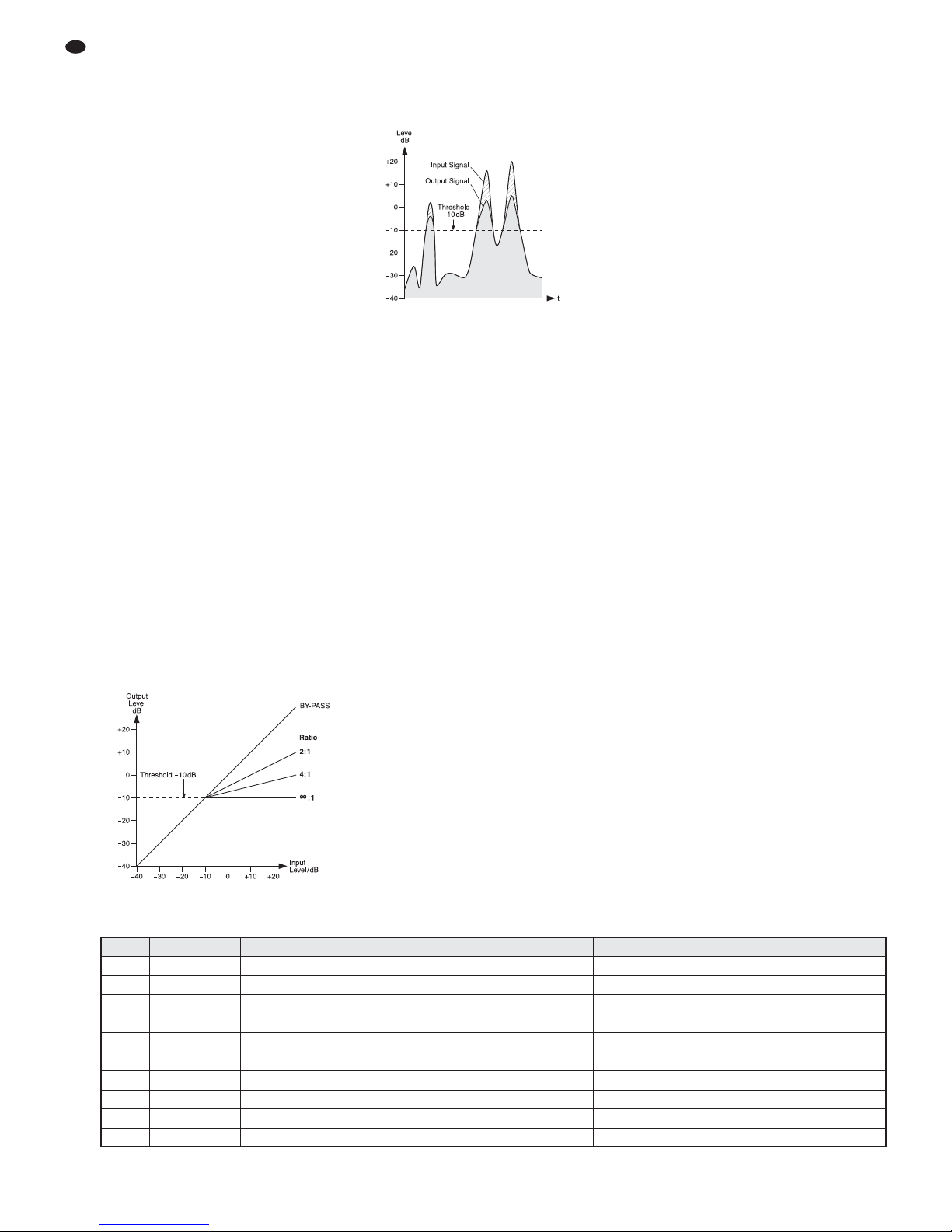
5.4 Using the signal compressor
The dynamic range of the sum signal can be
reduced by means of the integrated compressor
which attenuates the level above an adjustable
threshold. This is necessary when, for example,
the dynamic range of the audio signal is higher
than permitted by the recording system or amplifier system or when a small dynamic range is
desired (e. g. for background music). It is also
possible to attenuate signal peaks in order to
allow for a higher gain setting and thus obtain a
higher average volume.
1) Use the button COMP/ LIM (40) to switch on
the compressor. The LED next to the button
lights up.
2) Use the control THRESHOLD (32) to adjust
the threshold value at which the compressor
is to be switched on. Adjust the compression
ratio by means of the control RATIO (41):
Position “4”:
The ratio is 4 : 1; changing the input level by
8 dB above the threshold value will change
the output level by 2 dB.
Position “∞”:
The compressor operates as a signal limiter;
the output signal is approximately limited to
the value that has been adjusted by means of
the control THRESHOLD.
Hint: The higher the threshold value and the lower
the compression ratio, the more natural the dynamic
range.
3) The LED next to the control THRESHOLD
will light up when the input signal of the compressor exceeds the threshold value adjusted
and the output signal is compressed. The
level indicators (45) can also be used as an
adjustment aid. To make sure that the level
indicators indicate the output level, disengage
the button AFL / PFL – MAIN (43) beneath the
indicators.
As an example, figure 10 shows the output
level depending on the input level at a threshold value of
-
10 dB and at various compres-
sion ratios.
Fig. 10 Control characteristic lines of the compres-
sor at a threshold value of
-
10 dB
Figure 11 shows an input signal and the
resulting output signal at a threshold value of
-
10 dB and at a compression ratio of 2 : 1.
Below the threshold value, the signal remains
unchanged; above the threshold value, the
signal is compressed by a factor of 2.
Fig. 11 Input signal and output signal of the com-
pressor at a threshold value of
-
10 dB
and at a compression ratio of 2 : 1
5.5 Adjusting monitor send ways
When a monitor system is used to provide the
musicians with sound for on-stage monitoring,
the send ways AUX 1 and AUX 2 may serve as
monitor ways.
1) In each channel whose signal is to be used to
provide sound for on-stage monitoring, set
the switch PRE / POST (8) to the position
PRE.
2) Turn the control AUX 1 and / or AUX 2 (33) for
the volume of the monitor mix to the right until
the monitor signal can be easily heard via the
monitor system when the subsequent adjustments are made.
3) Use the controls AUX 1 and / or AUX 2 (9) to
add the channel signals to the monitor ways:
Turn the controls to the right, depending on
the desired volume ratio of the channels.
Make sure that the button MUTE (4) in the
corresponding input channels is disengaged.
4) Use the control FX 1 TO AUX 1 (24) to add the
effect signal of the internal effect processor
FX 1 (
chapter 5.6.1) to the monitor way
AUX 1, and use the control FX 2 TO AUX 2 of
the processor FX 2 to add the effect signal to
the monitor way AUX 2.
5) Use the control AUX 1 and / or AUX 2 (33) to
adjust the definite volume of the monitor signal.
5.6 Adding effects
5.6.1 Using internal effect processors
The two internal effect processors FX 1 and FX 2
allow for the generation of 100 different effects
that can be added to the sum signal and to the
monitor send ways AUX 1 and AUX 2. The send
ways AUX 3 and AUX 4 are used as effect ways
for the effect processors. The following de scribes how to adjust the effect way AUX 3 for
the processor FX 1; the procedure for adjusting
the effect way AUX 4 for the processor FX 2 is
identical.
1) To make sure that the effect adjustments are
audible, first set the controls FX 1 TO MAIN
(23) and AUX 3 (33) approximately to midposition.
2) Turn the knob PROGRAM (26) clockwise or
counterclockwise until the number of the
desired effect (
figure 12 Effect overview)
starts flashing on the display (27). Press the
knob to confirm the number: The number
stops flashing; the effect is switched on.
3) Use the controls AUX 3 (7) to add the signals
of the input channels to the effect way AUX 3.
With these controls, the desired effect intensity can be separately adjusted for each
channel. The signal is picked up after the
fader (1), i. e. the effect part of a channel is
always in proportion to the channel level
adjusted.
4) When the effect processor is switched on, the
LED next to the button PEAK / MUTE (25)
serves as an overload indicator with which
the level can be roughly checked. If the LED
lights up, turn back the control AUX 3 (33)
accordingly.
5) Use the control FX 1 TO MAIN to adjust the
effect intensity for the sum signal.
6) Use the control FX 1 TO AUX 1 (24) to add
the effect signal to the send way AUX 1 as
well.
7) Use a foot pedal connected to the jack
FOOT-SW 1/ 2 (50) [chapter 4.9] and the button PEAK / MUTE (25) to switch the effect
processor off and on (the button will not
engage). When the effect processor is
switched off, the LED next to the button
PEAK / MUTE will light up as an indication.
16
GB
Number Name Effect Parameter
00 – 09 Vocal reverb effect, ideally suited for vocals decay time 0.8 – 0.9 s, pre-delay time 10 – 45 ms
10 – 19 Small Room reverb effect: simulation of a small to medium-sized room decay time 0.7 – 2.1 s, pre-delay time 20 – 45 ms
20 – 29 Large Hall reverb effect: simulation of a large hall decay time 3.6 – 5.4 s, pre-delay time 23 – 55 ms
30 – 39 Echo echo effect delay time 145 – 205 ms
40 – 49 Echo + Verb combination of echo effect and reverb effect delay time 208 – 650 ms, decay time 1.7 – 2.7 s
50 – 59 Flange + Verb combination of flanger effect and reverb effect rate 0.8 – 2.52Hz, decay time 1.5 – 2.9 ms
60 – 69 Plate simulation of a classic reverberation plate with bright sound decay time 0.9 – 3.6s
70 – 79 Chorus + GTR guitar effect: Chorus rate 0.92 – 1.72Hz
80 – 89 Rotary + GTR guitar effect: Rotary (Leslie effect) modulation depth 20 – 80%
90 – 99 Tremolo + GTR guitar effect: Tremolo rate 0.6 – 5Hz
Fig. 12 Effect overview

5.6.2 External effect units
External effect units can be inserted into the
input channels via the jacks INSERT (13) or be
connected to the send ways AUX 1 – 4. For the
external effect units connected via the jacks
INSERT, no additional adjustments can be
made on the mixer; however, make sure that the
units are connected correctly and switched on
and that the correct adjustments have been
made. Otherwise, the signal way in the corresponding input channel will be interrupted and it
will not be possible to monitor the channel signal
or to add it to the sum signal.
Make the following adjustments for each of
the units connected to the send ways AUX 1 – 4:
1) To make sure that the subsequent effect
adjustments are audible, first set the corresponding output controls and input controls
approximately to mid-position:
according to the send way used
the corresponding control AUX 1, 2, 3 or 4
(33)
according to the input used
the fader AUX RTN 1 or 2 (19)
or
the fader (1) of the corresponding input
channel
2) Switch on the desired effect at the effect unit
and adjust the processed effect signal as the
output signal.
3) Depending on the send way used as the
effect way, use the control AUX 1, 2, 3 or 4 (7,
9) to add the channel signals to the effect
way. With these controls, the desired effect
intensity can be separately adjusted for each
channel.
Before the send ways 1 and 2 are used as
effect ways, set the switch PRE / POST (8) to
the position POST. Thus, the signal is picked
up after the fader (1) [as it is for the send
ways 3 and 4]; i. e. the effect part of a channel is always in proportion to the channel
level adjusted.
Notes
1. If the output of the effect unit is connected to the
line input of an input channel, set the corresponding control AUX … (7, 9) of the channel to minimum; otherwise, there will be feedback: If, for
example, the send way 3 is used for the effect
unit, set the control AUX 3 to minimum!
2. The signals of the effect ways 3 and 4 are also
sent to the inputs of the internal effect processors
(
chapter 5.6.1). Therefore, use the controls
FX … TO MAIN (23) to separately adjust the
intensity of the internal effects as required or
mute the internal effects by means of the button
MUTE (25).
4) Use the controls AUX … (33) to adjust the
level of the total signal of a send way so that
the effect unit is not overloaded.
5) Use the appropriate input control to add the
signal coming from the effect unit; with the
input control, the effect intensity for all channels can be jointly adjusted:
— If the effect unit is connected to the input
AUX RETURN 1 or 2 (28), use the fader
AUX RTN 1 or 2 (19) to add the effect signal to the sum signal.
— If the effect unit is connected to the line
input (14, 15) of an input channel, use the
appropriate channel fader (1) to add the
effect signal to the sum signal. Additionally, the appropriate controls AUX 1 and/
or AUX 2 (9) can be used to add the effect
signal to the send ways 1 and / or 2 (e. g.
when these send ways are used as monitor send ways).
6) To temporarily mute the effect signal, press
the button MUTE (4, 22) of the channel to
whose input the effect unit is connected.
5.7 Monitoring via headphones
or a control monitor system
For monitoring via headphones or a control monitor system connected to the jack PHONES /
CTRL-ROOM (51), the following signals can be
selected:
1. The stereo sum signal post-fader, i.e. after
the fader MAIN MIX (39)
Disengage the button AFL / PFL – MAIN (43)
beneath the level indicators. The LED next to
the button must not light up.
2. The signals of the individual input chan-
nels pre-fader, i. e. ahead of the channel
fader (1), the button MUTE (4) and the control
PAN (5) or BAL (6)
Press the button PFL (3) of the desired channel. The LED next to the button lights up as
an indication. Additionally, press the button
AFL / PFL – MAIN (43) beneath the level indicators. The LED next to the button lights up.
3. The mono sum signal post-fader, i. e. after
the fader MONO (30)
Press the button AFL (31) above the fader
MONO. Additionally, press the button AFL /
PFL – MAIN (43) beneath the level indicators.
4. The input signals of the jacks AUX RE -
TURN 1 and 2 (28) pre-fader, i. e. ahead of
the faders AUX RTN 1 and 2 (19)
Press the button PFL (21) above the fader
AUX RTN 1 or 2. Additionally, press the button AFL/PFL – MAIN (43) beneath the level
indicators.
5. The input signal of the jacks AUX IN /
TAPE IN (29) post-fader, i.e. after the control
2-TRACK IN (34)
Press the button AFL (44) beneath the control 2-TRACK IN (34). Additionally, press the
button AFL / PFL – MAIN (43) beneath the
level indicators. Turn the control 2-TRACK IN
to the right so that the signal is audible. If the
input signal is not to be added to the sum signal, press the button MUTE (46) beforehand.
Notes
1. The level indicators (45) always indicate the sig-
nal that has been selected for monitoring.
2. The button AFL / PFL – MAIN (43) beneath the
level indicators takes priority over the buttons
PFL (3, 21) and the buttons AFL (31, 44). When
the button AFL / PFL – MAIN is disengaged, the
stereo sum signal will be monitored and indicated.
The buttons PFL and AFL, however, have the
same priority. If some of these buttons are
pressed at the same time and if the button AFL /
PFL – MAIN is pressed as well, the mixed signal
of the corresponding sources will be monitored
and indicated.
17
GB
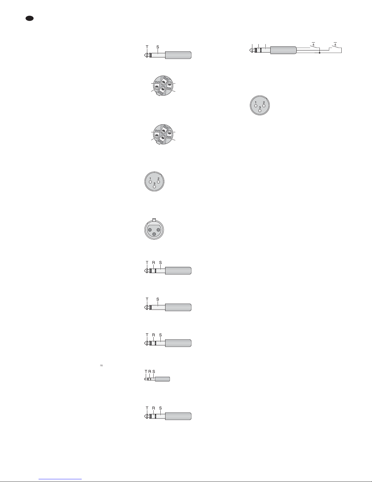
6 Specifications
Block diagram see page 61
Output power
rms power
at 4 Ω speaker: . . . . 2 × 400 W
at 8 Ω speaker: . . . . 2 × 300 W
bridged operation: . . 1 × 700 W at 8 Ω
Maximum power: . . . . 2 × 600 W at 4Ω
Inputs
(sensitivity/ impedance; connection)
Mic: . . . . . . . . . . . . . . 0.5 mV/3kΩ; XLR,
balanced
Line (mono channel): . 2 mV/10kΩ;
6.3 mm jack, bal.
Line (stereo channel): 8 mV/10 kΩ;
6.3 mm jack, bal.
Tape In: . . . . . . . . . . . 60 mV/8kΩ; RCA,
3.5 mm jack, unbal.
Aux Return: . . . . . . . . 80 mV/10 kΩ;
6.3 mm jack, bal.
Insert (Return): . . . . . . 80 mV/9kΩ;
6.3 mm jack, unbal.
Outputs
(level / impedance; connection)
Main Mix Out, stereo: . 1.5 V (at indication
0 dB) / 120 Ω;
XLR, bal. and
6.3 mm jack, unbal.
Mono Out: . . . . . . . . . 500 mV/ 120 Ω;
6.3 mm jack, unbal.
Tape Out, stereo: . . . . 680 mV/ 1 kΩ; RCA
Aux Sends, mono: . . . 10 V/ 120 Ω;
6.3 mm jack, unbal.
Headphone impedance: ≥ 8 Ω
Frequency range: . . . . . 20 – 20 000Hz
THD: . . . . . . . . . . . . . . . < 0.04 %
S/N ratio: . . . . . . . . . . . . 89 dB
Crosstalk: . . . . . . . . . . .
-
63 dB
Equalizer controls
bass frequencies: . . . . ±15 dB / 80 Hz
high frequencies: . . . . ±15 dB / 12 kHz
mid-frequencies
mono channel: . . . . . . ±15 dB / 100 – 8000 Hz
mid-frequencies
stereo channel: . . . . . ±15 dB / 500 Hz
±15 dB / 3 kHz
Equalizer: . . . . . . . . . . . ±15 dB at
63 / 160 / 400 Hz /
1/ 2.5 / 6.3 /16 kHz
Low cut filter: . . . . . . . . . 75 Hz / 18 dB per oct.
Compressor
threshold: . . . . . . . . . .
-
40 dB to +22 dB
ratio: . . . . . . . . . . . . . . 2 : 1 to ∞ : 1
attack time: . . . . . . . . 1 ms
release time: . . . . . . . 2 s
Phantom power
for Mic 1 – 12: . . . . . . . . +48 V
Voltage for console light: 12 V /500 mA
Mains voltage: . . . . . . . . 230 V~ / 50 Hz
Power consumption
at no-load operation: . 60 VA
at maximum output
power: . . . . . . . . . . . . 1250 VA
Ambient temperature: . . 0 – 40 °C
Dimensions (W×H×D): 545 × 145 × 465 mm
Weight: . . . . . . . . . . . . . 12.5 kg
6.1 Plug configuration
Speaker connections
for stereo operation or 2-channel operation
2-pole 6.3 mm plug
SPEAKON
®
compatible plug
Speaker connection at jack “A”
for bridged operation
SPEAKON
®
compatible plug
Microphone connections
XLR plug for balanced connection
Line signal connections
XLR inline jack for balanced connection
3-pole 6.3 mm plug
for balanced connection
2-pole 6.3 mm plug
for unbalanced connection
6.3 mm stereo plug
for stereo signals (Phones / CTRL-Room)
3-pole 3.5 mm plug
for stereo signals (Aux In)
3-pole 6.3 mm plug
for jacks INSERT
Connection for two foot pedals
3-pole 6.3 mm plug
FX 1, FX 2 = momentary pushbuttons for the
effect processors FX 1 and FX 2
Connection for a console light
XLR plug
Subject to technical modification.
1 = negative pole 12 V
2 = positive pole 12 V
3 = free
TRS
FX1
T
S
FX2
R
T = send (output)
R = return (input)
S = ground
T = left channel
R = right channel
S = ground
T = left channel
R = right channel
S = ground
T = signal
S = ground
T = signal +
R = signal
-
S = ground
1 = ground
2 = signal +
3 = signal
-
21
3
1 = ground
2 = signal +
3 = signal
-
1+ = positive pole
2+ = negative pole
1+2
-
1
-
2+
1+ = positive pole
1
-
= negative pole
1+2
-
1
-
2+
T = positive pole
S = negative pole
18
GB
All rights reserved by MONACOR®INTERNATIONAL GmbH & Co. KG. No part of this instruction
manual may be reproduced in any form or by any means for any commercial use.

19
 Loading...