

IMG STAGE LINE PARL-30SPOT Instruction Manual

ELECTRONICS FOR SPECIALISTS ELECTRONICS FOR SPECIALISTS ELECTRONICS FOR SPECIALISTS ELECTRONICS FOR SPECIALISTS
BEDIENUNGSANLEITUNG
INSTRUCTION MANUAL
MODE D’EMPLOI
ISTRUZIONI PER L’USO
GEBRUIKSAANWIJZING
MANUAL DE INSTRUCCIONES
INSTRUKCJA OBSŁUGI
SIKKERHEDSOPLYSNINGER
SÄKERHETSFÖRESKRIFTER
TURVALLISUUDESTA
PARL-30SPOT
Bestell-Nr. • Order No. 38.3100
DMX-LED-Scheinwerfer
DMX LED Spotlight
2
DMX OUT
3
12
DMX IN
ONLY FOR
REMOTE
CONTROL
DMX
ADDRESS
SETTING
1 2
6 7 8 9
3 4 5 1
10 11 12
13
14
15
➀
➁ ➂

3
ELECTRONICS FOR SPECIALISTS ELECTRONICS FOR SPECIALISTS ELECTRONICS FOR SPECIALISTS ELECTRONICS FOR SPECIALISTS
Deutsch ..........Seite 4
English ...........Page 8
Français ..........Page 12
Italiano...........Pagina 16
Nederlands .......Pagina 20
Español ..........Página 24
Polski ............Strona 28
Dansk ............Sida 32
Svenska ..........Sidan 33
Suomi............Sivulta 34
4
Deutsch
DMX-LED-Scheinwerfer
Diese Anleitung richtet sich an den Installateur des
Geräts und an den Bediener mit Grundkenntnissen in
der DMX-Steuerung. Bitte lesen Sie die Anleitung vor
dem Betrieb gründlich durch und heben Sie sie für ein
späteres Nachlesen auf.
Auf der Seite 2 finden Sie alle beschriebenen
Bedienelemente und Anschlüsse.
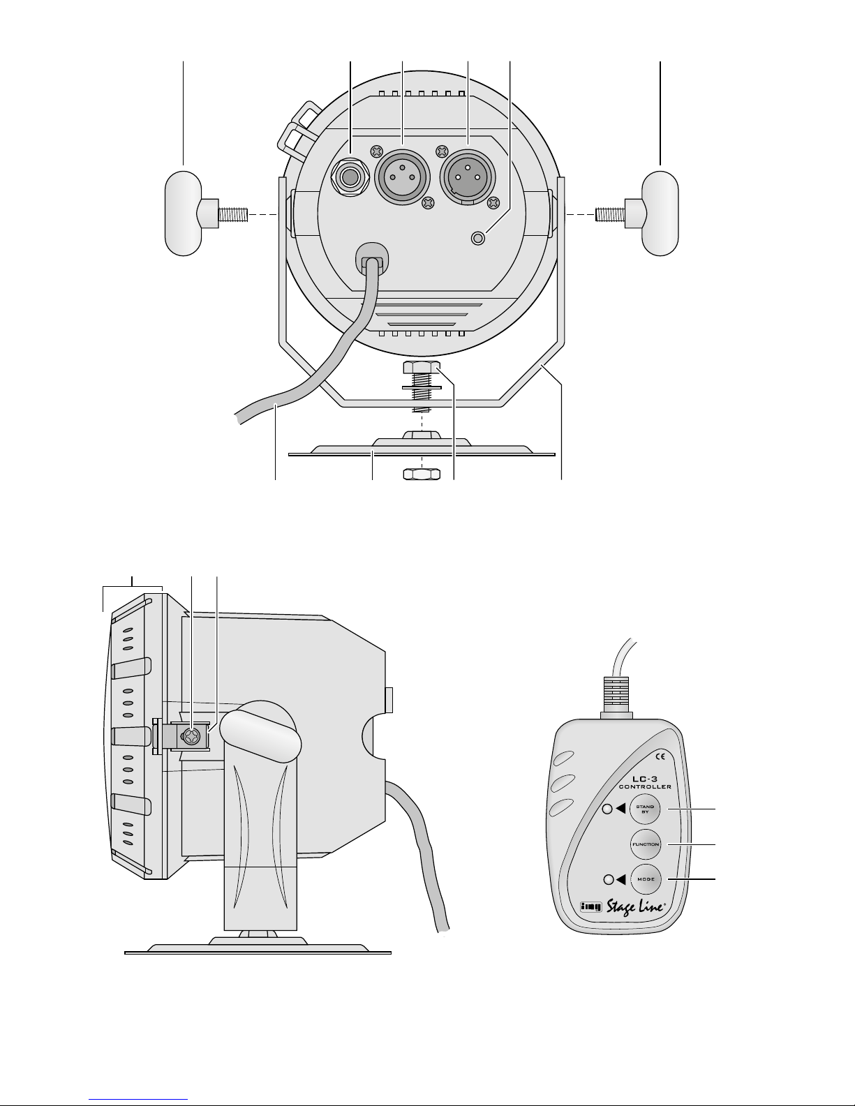
1 Übersicht der Bedienelemente
und Anschlüsse
1.1 Scheinwerfer
1 Feststellschrauben für den Montagebügel (9)
2 Anschlussbuchse für die Fernbedienung LC-3
3
DMX-Signal-Ausgang (3-pol. XLR) zum Anschluss
an den DMX-Eingang eines weiteren DMXLichteffektgeräts;
1 = Masse, 2 = DMX−, 3 = DMX+
4 DMX-Signal-Eingang (3-pol. XLR);
1 = Masse, 2 = DMX−, 3 = DMX+
5 Taste für die DMX-Adresseneinstellung
(siehe Kapitel 7.2)
6 Netzkabel zum Anschluss an eine Steckdose
(230 V/ 50 Hz)
7
Montageplatte zur Befestigung an einer Wand
oder Decke
8 Schraube für die Montageplatte
9 Montagebügel
10 Gehäusedeckel mit Kunststoffscheibe
11 Feststellschraube für die Verriegelung (12)
12 Verriegelung für den Gehäusedeckel
1.2 Fernbedienung LC-3
Die Fernbedienung ist als Zubehör erhältlich und
gehört nicht zum Lieferumfang des Scheinwerfers.
13 Taste STAND BY für die Funktion Blackout
(Licht aus)
14
Taste FUNCTION zur Auswahl verschiedener Lichtwechselfunktionen in Abhängigkeit von dem mit
der Taste MODE gewählten Betriebsmodus
15 Taste MODE zum Umschalten zwischen
Sound-Modus 1 (LED leuchtet nicht)
Manual-Modus (LED leuchtet)
Sound-Modus 2 (LED blinkt langsam)
Auto-Modus (LED blinkt schnell)
Hinweis: Zur Steuerung über die Fernbedienung darf am
Eingang DMX IN (4) kein DMX-Signal anliegen.
2 Hinweise für
densicherenGebrauch
Der Scheinwerfer entspricht allen relevanten Richtlinien der EU und trägt deshalb das -Zeichen.
WARNUNG Das Gerät wird mit lebensgefährlicher
Netzspannung versorgt. Nehmen Sie
deshalb niemals selbst Eingriffe am
Gerät vor und stecken Sie nichts in die
Lüftungsöffnungen. Es besteht die Gefahr eines elektrischen Schlags.
•
Verwenden Sie den Scheinwerfer nur im Innenbereich und schützen Sie ihn vor Tropf- und Spritzwasser sowie vor hoher Luftfeuchtigkeit. Der zulässige
Einsatztemperaturbereich beträgt 0 – 40 °C.
•
Zie hen Sie sofort den Netzstecker aus der Steckdose,
1. wenn sichtbare Schäden am Gerät oder an der
Netzanschlussleitung vorhanden sind,
2.
wenn nach einem Sturz oder Ähnlichem der Verdacht auf einen Defekt besteht,
3. wenn Funktionsstörungen auftreten.
Geben Sie das Gerät in jedem Fall zur Reparatur in
eine Fachwerkstatt.
•
Ein beschädigtes Netzkabel darf nur durch eine
Fachwerkstatt ersetzt werden.
•
Ziehen Sie den Netzstecker nie am Kabel aus der
Steckdose, fassen Sie immer am Stecker an.
•
Verwenden Sie für die Reinigung nur ein trockenes,
weiches Tuch, niemals Wasser oder Chemikalien.
•
Wird der Scheinwerfer zweckentfremdet, nicht
sicher montiert, falsch be dient oder nicht fachgerecht repariert, kann keine Haftung für daraus
resultierende Sach- oder Personenschäden und
keine Garantie für den Scheinwerfer übernommen
werden.
Soll der Scheinwerfer endgültig aus dem
Betrieb genommen werden, übergeben Sie
ihn zur umweltgerechten Entsorgung einem
örtlichen Recyclingbetrieb.
3 Einsatzmöglichkeiten
Der Scheinwerfer ist für den Einsatz auf Bühnen, in
Diskotheken und Partyräumen oder zu Dekorationszwecken geeignet. Er erzeugt far bi ges Licht über
superhelle 5-mm-LEDs, die in Blau, Rot und Grün
leuchten. Es sind auch musikgesteuerte Farbwechsel, langsame Farbüberblendungen und StroboskopEffekte möglich.
Der Scheinwerfer ist für die Steuerung über ein
DMX-Lichtsteuergerät ausgelegt (4 DMX-Steuerkanäle), kann aber auch ohne Steuergerät oder mit
der als Zubehör erhältlichen Fernbedienung LC-3
betrieben werden.
5
Deutsch
4 Montage
•
Platzieren Sie das Gerät immer so, dass im Betrieb
eine ausreichende Luftzirkulation gewährleistet ist.
Die Lüftungsöffnungen am Gehäuse dürfen auf kei
-
nen Fall abgedeckt werden (z. B. durch Vorhänge).
•
Der Abstand zum angestrahlten Objekt sollte mindestens 10 cm betragen.
1)
Den Montagebügel (9) mit den beiden Knebelschrauben (1) am Scheinwerfergehäuse festschrauben.
2)
Den Scheinwerfer über den Montagebügel (9)
befestigen, z. B. mit einer stabilen Montageschraube oder einer Lichtstrahler-Halterung
(C- Haken) an einer Traverse.
Soll der Scheinwerfer an einer Decke oder
Wand befestigt werden, die Montageplatte (7)
an den Montagebügel nach der Abbildung 1 festschrauben. Die Montageplatte mit dem Scheinwerfer an geeignerter Stelle der Decke bzw. Wand
festschrauben.
WARNUNG
Der Scheinwerfer muss fachgerecht
und sicher montiert werden. Wird er
an einer Stelle installiert, unter der sich
Personen aufhalten können, muss er
zusätzlich gesichert werden (z. B. durch ein Fang
seil am Montagebügel; das Fangseil so befestigen,
dass der Fallweg des Gerätes nicht mehr als 20 cm
betragen kann).
3) Zum Ausrichten des Scheinwerfers die zwei Feststellschrauben (1) am Montagebügel lösen. Die
ge wünschte Neigung des Scheinwerfers einstellen
und die Schrauben wieder fest anziehen.
Ist der Scheinwerfer an der Montageplatte (7)
festgeschraubt, ggf. die Schraube (8) etwas lösen,
den Montagebügel (9) wie gewünscht drehen und
die Schraube wieder festziehen.
5 Inbetriebnahme
WARNUNG
Blicken Sie nicht direkt in die LEDs, das
kann zu Augenschäden führen.
Beachten Sie, dass sehr schnelle Lichtwechsel bei fotosensiblen Menschen
und Epilep tikern epileptische Anfälle
aus lösen können!
Zum Einschalten des Scheinwerfers den Ste cker des
Netzkabels (6) in eine Steckdose (230 V/ 50 Hz) ste cken,
zum Ausschalten ihn wieder herausziehen.
Um einen besseren Bedienkomfort zu erhalten, ist
es empfehlenswert, den Scheinwerfer an eine Steckdose an zu schließen, die sich über einen Lichtschalter
ein- und ausschalten lässt.
Vorsicht: Der Scheinwerfer darf nicht über einen
Dimmer an die Netzspannung angeschlossen werden!
6 Betrieb ohne Steuergerät
Empfängt der Scheinwerfer kein DMX-Steuersignal,
wechselt er selbstständig mit langsamen Überblendungen die Farben.
Läuft Musik mit deutlichem Rhythmus im Bassbereich in ausreichender Lautstärke, wechselt der
Scheinwerfer, gesteuert über ein internes Mikrofon,
die Farbe im Takt der Musik. Sollte die Musiksteuerung
nicht optimal funktionieren, die Lautstärke erhöhen
oder den Abstand zwischen Schallquelle und Scheinwerfer verringern.
6.1 Zusammenschalten mehrerer Scheinwerfer
Es lassen sich mehrere PARL-30SPOT zusammenschalten, um so synchron die Farben zu wechseln oder über
das interne Mikrofon des Hauptgerätes alle weiteren
Nebengeräte im gleichen Rhythmus zu steuern.
Dazu den Anschluss DMX OUT (3) des Hauptgerätes über ein 3-poliges XLR-Kabel (z. B. Serie
CDMXN-... aus dem Sortiment von IMG STAGELINE)
mit dem Anschluss DMX IN (4) des ersten Nebengerätes verbinden. Den Anschluss DMX OUT des ersten
Nebengerätes mit dem Anschluss DMX IN des zweiten
Nebengerätes verbinden usw.
6.2 Fernbedienung über LC-3
Über die als Zubehör erhältliche Fernbedienung LC-3
können zusätzlich zu der Musiksteuerung verschiedene Funktionen gesteuert werden.
1) Die Fernbedienung an die Buchse REMOTE CONT-
ROL (2) anschließen.
2)
Am Eingang DMX IN (4) darf kein DMX-Signal
anliegen.
3) Über den Ausgang DMX OUT (3) können weitere
PARL-30SPOT angeschlossen werden (☞Kapitel6.1), um diese über die Fernbedienung gemeinsam mit dem Hauptgerät zu steuern.
4) Mit der Taste STAND BY (13) lässt sich die Funktion
Blackout ein- und ausschalten. Bei eingeschalteter
Funktion wird das Licht abgeblendet und die LED
neben der Taste leuchtet.
5)
Mit der Taste MODE (15) den Betriebsmodus
wählen:
a) Nach dem Einschalten des Scheinwerfers ist der
Modus SOUND 1 aktiviert. Die LED neben der
Taste MODE leuchtet nicht. Bei gedrückt gehaltener Taste FUNCTION (14) wird ein musikabhängiger Stroboskop-Effekt erzeugt. Bei
jedem neuen Drücken der Taste wechselt dieser
zwischen weißem Licht, wechselndem farbigem
Licht (bei mehreren Scheinwerfern als kurze
Sequenz mit nur einem Blitz pro Scheinwerfer;
die Farbe ist bei allen Scheinwerfern gleich) und
wechselndem farbigem Licht mit unterschiedlichen Farben bei mehreren Scheinwerfern.

6
Deutsch
b) Zum Umschalten auf den Modus MANUAL die
Taste MODE einmal drücken. Die LED neben der
Taste leuchtet. Mit der Taste FUNCTION kann
jetzt eine der folgenden Farben ausgewählt
werden:
Weiß, Rot, Blau, Violett, Orange, Grün, Gelb,
Magenta, Cyan
c) Zum Umschalten auf den Modus SOUND 2 die
Taste MODE ein weiteres Mal drücken. Die LED
neben der Taste blinkt langsam. Mit der Taste
FUNCTION kann durch wiederholtes Drücken
zwischen fünf verschiedenen musikgesteuerten
Farbwechseloptionen und Sequenzen gewählt
werden. Diese Optionen sind nur mit mehreren
zusammengeschalteten Scheinwerfern sinnvoll.
d)
Zum Umschalten auf den Modus AUTO die Taste
MODE ein weiteres Mal drücken. Die LED neben
der Taste blinkt schnell. In dieser Betriebsart werden die Farben automatisch durch Überblenden
gewechselt. Laufende Musik hat hierauf keinen
Einfluss. Mit der Taste FUNCTION kann durch
wiederholtes Drücken zwischen drei verschiedenen Überblendgeschwindigkeiten gewählt
werden.
Zum Zurückschalten auf den Modus SOUND 1 die
Taste MODE erneut drücken.
7 Bedienung über ein
Lichtsteuergerät
Zur Bedienung über ein Lichtsteuergerät mit DMX512Protokoll (z. B. DMX-1440 oder DMX-510USB von
IMG STAGELINE) verfügt der Scheinwerfer über vier
Steuer ka näle. Die Funktionen der Kanäle und die
DMX-Werte finden Sie im Kapitel 9.1.
7.1 Anschluss
Für die DMX-Signalübertragung sollten spezielle Kabel
verwendet werden (z. B. Kabel der CDMXN-Serie von
IMG STAGELINE). Bei Leitungslängen ab 150 m oder
bei der Steuerung von mehr als 32 Geräten über einen
DMX-Ausgang wird grundsätzlich das Zwischenschalten eines DMX-Aufholverstärkers empfohlen
(z. B. SR-103DMX).
1) Den DMX-Eingang (4) mit dem DMX-Ausgang des
Lichtsteuergerätes verbinden.
2) Den DMX-Ausgang (3) mit dem DMX-Eingang des
nächsten Lichteffektgerätes verbinden. Dessen Ausgang wieder mit dem Eingang des nachfolgenden
Gerätes verbinden usw., bis alle Licht effektgeräte
in einer Kette angeschlossen sind.
3)
Den DMX-Ausgang des letzten DMX-Geräts der
Kette mit einem 120-Ω-Widerstand (> 0,3 W) abschließen: An die Pins 2 und 3 eines XLR-Steckers
den Widerstand anlöten und den Ste cker in den
DMX-Ausgang stecken oder einen entsprechenden
Abschlussstecker (z. B. DLT-123 von IMG STAGELINE) verwenden.
7.2 Startadresse einstellen
Um den Scheinwerfer mit einem Lichtsteuergerät bedienen zu können, muss die DMX-Startadres se für
den 1. DMX-Kanal eingestellt werden. Ist z. B. am
Steuergerät die Adresse 17 zum Steuern der Farbe
Rot vorge sehen, am Scheinwerfer die Start adresse
17 einstellen. Die anderen Funktionen des Scheinwerfers (Grün, Blau, Dimmer) sind dann automatisch
den drei folgenden Kanälen (in diesem Beispiel 18 –
20) zugeordnet. Als nächstmögliche Startadresse für
das folgende DMX-gesteuerte Gerät könnte dann bei
diesem Beispiel die Adresse 21 verwendet werden.
Zum Einstellen der Adresse stehen die folgenden zwei
Methoden zur Verfügung:
7.2.1 Automatische Adresseneinstellung
Diese Methode ist sinnvoll, wenn mehrere PARL30SPOT verwendet werden und deren Adressen im
unteren Bereich liegen sollen:
1)
Den DMX-Eingang (4) des ersten Scheinwerfers
vom Steuergerät trennen oder das Steuergerät ausschalten, sodass kein DMX-Signal am Eingang des
Scheinwerfers anliegt.
2)
Die Taste DMX ADDRESS SETTING (5) am ersten
Scheinwerfer fünf Sekunden lang drücken. Der
Scheinwerfer und die an ihm angeschlossenen
Scheinwerfer werden dann dunkel.
3) Die Verbindung zum Steuergerät wiederherstellen
bzw. das Steuergerät wiedereinschalten.
Die Startadresse des ersten Scheinwerfers ist nun auf
1 eingestellt, die Startadressen der folgenden Scheinwerfer auf 5, 9, 13 usw.
7
Deutsch
7.2.2 Adresseneinstellung über das Steuergerät
Mit dieser Methode kann einem Scheinwerfer auf
einfache Weise eine beliebige Startadresse zugewiesen werden:
1)
Am Steuergerät den DMX-Wert des Kanals, der
der einzustellenden Startadresse entspricht, auf das
Maximum (255) stellen. Die Werte aller anderen
DMX-Kanäle auf Null stellen. Soll z. B. die Startadresse 17 eingestellt werden, den Kanal 17 am
Steuerpult voll aufziehen und alle anderen Kanäle
auf Null stellen.
2) Bei allen Scheinwerfern, die diese Startadresse erhalten sollen, kurz die Taste DMX ADDRESS SETTING (5) drücken.
Diese Bedienschritte wiederholen, bis jeder Scheinwerfer seine Adresse erhalten hat.
7.3 Steuerung mit dem LED-4C
Das Gerät LED-4C von IMG STAGELINE ist ein einfach zu bedienendes Steuerpult speziell für diese
LED-Scheinwerfer. Es verfügt über 4 Kanäle, sodass
alle daran angeschlossenen Scheinwerfer nur synchron
gesteuert werden können.
Die Startadresse der Scheinwerfer auf 1 oder auf
ein Vielfaches von 4 + 1 (5, 9, 13, … max. 61) einstellen, ☞Kapitel 7.2.1. Genaueres zur Bedienung
entnehmen Sie bitte der Anleitung zum LED-4C.
8 Scheinwerfer säubern
Die Kunststoffscheibe des Scheinwerferdeckels (10)
sollte in regelmäßigen Abständen, je nach Verschmutzung durch Staub, Rauch oder andere Schmutzpartikel, von außen und ggf. auch von innen gereinigt
werden. Nur dann kann das Licht in maximaler Helligkeit abgestrahlt werden.
1) Zum Säubern ein weiches, sauberes Tuch und ein
mildes Reinigungsmittel verwenden. Anschließend
die Kunststoffscheibe trocken wischen.
2)
Um die Scheibe von innen reinigen zu können, muss
der Scheinwerferdeckel (10) abgenommen werden.
VORSICHT! Vor dem Öffnen des Scheinwerfers un-
bedingt den Netzstecker aus der Steckdose ziehen.
a) Die Feststellschraube (11) lösen und den Riegel
(12) nach hinten schieben.
b)
Den Scheinwerferdeckel ein Stück gegen den
Uhrzeigersinn drehen, sodass er ausrastet und
abgenommen werden kann.
c) Die Scheibe von innen reinigen und den Schein-
werfer in umgekehrter Reihenfolge wieder zusammensetzen.
9 Technische Daten
Stromversorgung: . . . . . .230 V/ 50 Hz
Leistungsaufnahme: . . . .10 VA
Leuchtmittel: . . . . . . . . . .superhelle 5-mm-LEDs
Anzahl: . . . . . . . . . . . .90
24 rote
33 grüne
33 blaue
Abstrahlwinkel: . . . . . .20°
Einsatztemperatur:
. . . . .0 – 40 °C
Abmessungen: . . . . . . . .⌀ 120 mm × 120 mm
Gewicht: . . . . . . . . . . . . .1 kg
Kabellänge: . . . . . . . . . . .1,2 m
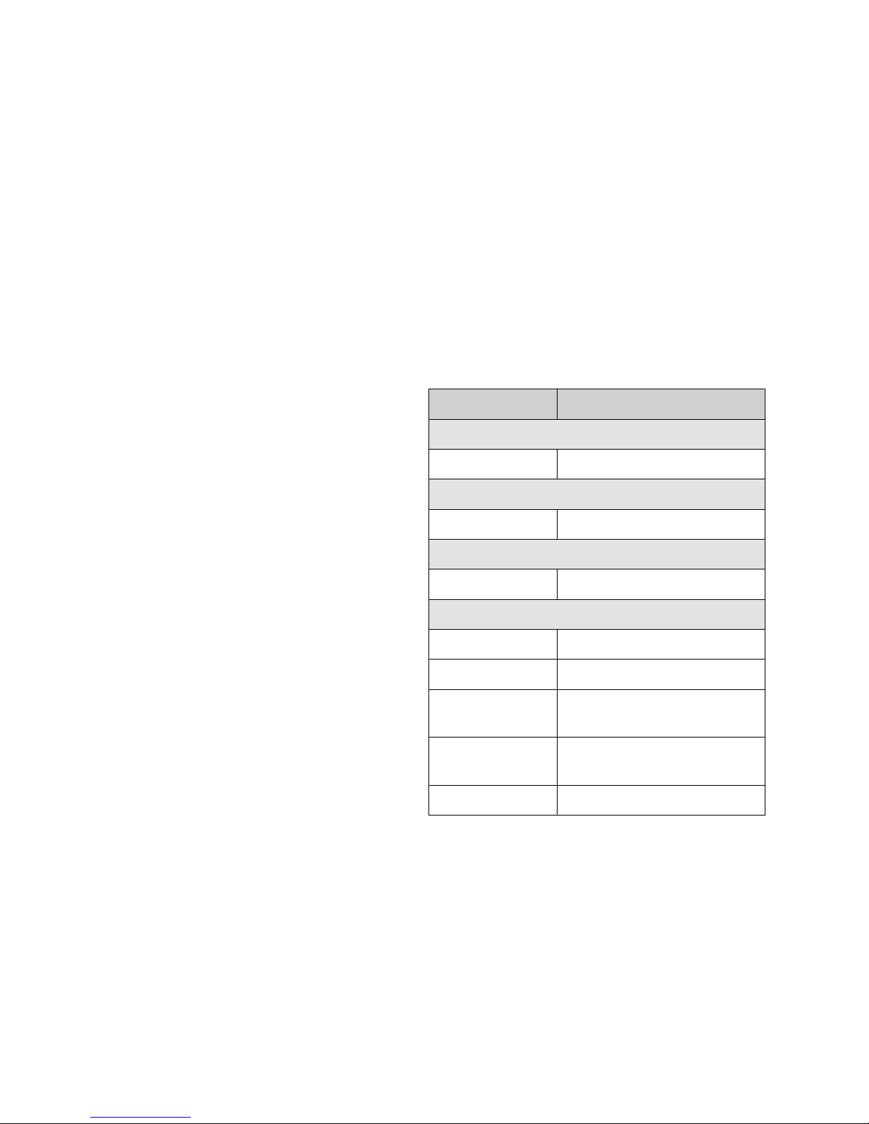
9.1 DMX-Kanäle
DMX Wert Funktion
Kanal 1: Rot-Anteil
0 – 255 Helligkeit Rot
Kanal 2: Grün-Anteil
0 – 255 Helligkeit Grün
Kanal 3: Blau-Anteil
0 – 255 Helligkeit Blau
Kanal 4: Dimmer / Stroboskop/ Musik
0 – 7 LEDs aus
8 – 190 Dimmer
191 – 200
musikgesteuerter Farbwechsel
über das integrierte Mikrofon
201 – 247
Stroboskop-Effekt:
langsam
schnell
248 – 255 volle Helligkeit
Änderungen vorbehalten.
Diese Bedienungsanleitung ist urheberrechtlich für MONACOR ® INTERNATIONAL GmbH & Co. KG geschützt. Eine
Reproduktion für eigene kommerzielle Zwecke – auch auszugsweise – ist untersagt.
8
English
DMX LED Spotlight
These instructions are intended for installers of the unit
and for users with basic knowledge in DMX control.
Please read the instructions carefully prior to operation
and keep them for later reference.
All operating elements and connections described
can be found on page 2.
1 Operating Elements
andConnections
1.1 Spotlight
1 Locking screws for the mounting bracket (9)
2 Connection jack for the remote control LC-3
3 DMX signal output (3-pole, XLR) for connection
to the DMX input of another DMX light effect
unit;
1 = ground, 2 = DMX−, 3 = DMX+
4 DMX signal input (3-pole, XLR);
1 = ground, 2 = DMX−, 3 = DMX+
5 Button for adjusting the DMX address
(see chapter 7.2)
6 Mains cable for connection to a socket
(230 V/ 50 Hz)
7 Mounting plate for fixing the spotlight to a wall
or ceiling
8 Screw for the mounting plate
9 Mounting bracket
10 Housing cover with plastic pane
11 Locking screw for the latch (12)
12 Latch for the housing cover
1.2 Remote control LC-3
The remote control is available as an accessory and
not supplied with the LED spotlight.
13 Button STAND BY for the function Blackout
(light off)
14
Button FUNCTION for selecting various light
changing functions depending on the operating
mode selected with the button MODE
15 Button MODE for switching over between
Sound mode 1 (LED off)
Manual mode (LED on)
Sound mode 2 (LED flashing slowly)
Auto mode (LED flashing rapidly)
Note: For control via the remote control, there must be
no DMX signal at the input DMX IN (4).
2 Safety Notes
The spotlight corresponds to all relevant directives of
the EU and is therefore marked with
.
WARNING
The spotlight is supplied with hazardous mains voltage. Leave servic ing to
skilled personnel only and do not insert
anything into the air vents, otherwise
you will risk an electric shock!
•
The spotlight is suitable for indoor use only. Protect
it against dripping water, splash water and high
humidity. The admissible ambient temperature
range is 0 – 40 °C.
•
Immediately disconnect the mains plug from the
mains socket
1. in case of visible damage to the unit or to the
mains cable,
2.
if a defect might have occurred after the unit was
dropped or suffered a similar accident,
3. if malfunctions occur.
In any case the unit must be repaired by skilled
personnel.
•
A damaged mains cable must be replaced by skilled
personnel only.
•
Never pull the mains cable for disconnecting the mains
plug from the mains socket, always seize the plug.
•
For cleaning only use a dry, soft cloth, never use
chemicals or water.
•
No guarantee claims for the spotlight and no liability for any resulting personal damage or material
damage will be accepted if the spotlight is used for
other purposes than originally intended, if it is not
safely mounted or correctly operated, or if it is not
repaired in an expert way.
•
Important for U. K. Customers!
The wires in this mains lead are coloured in accordance with the following code:
green / yellow = earth
blue = neutral
brown = live
As the colours of the wires in the mains lead of this
appliance may not correspond with the coloured
markings identifying the terminals in your plug,
proceed as follows:
1. The wire which is coloured green and yellow must
be connected to the terminal in the plug which is
marked with the letter E or by the earth symbol
, or coloured green or green and yellow.
2. The wire which is coloured blue must be con
nected to the terminal which is marked with the
letter N or coloured black.
3. The wire which is coloured brown must be connected to the terminal which is marked with the
letter L or coloured red.
Warning – This appliance must be earthed.
9
English
If the spotlight is to be put out of operation
definitively, take it to a local recycling plant
for a disposal which is not harmful to the
environment.
3 Applications
This spotlight is suited for applications on stage, in
discothèques and party rooms or for decoration purposes. It creates coloured light via extra bright 5 mm
LEDs in blue, red, and green. Music-controlled colour
changes, gradual transitions from one colour to another, and stroboscopic effects will be possible.
The spotlight is designed for control via a DMX
light controller (4 DMX control channels), however, it
can also be operated without a controller or with the
remote control LC-3 available as an accessory.
4 Mounting
•
Always place the spotlight in such a way that a
sufficient air circulation will be ensured during operation. Never cover the air vents of the housing
(e. g. by curtains).
•
The minimum distance to the illuminated object
should be 10 cm.
1) Fasten the mounting bracket (9) to the housing of
the spotlight by means of the two knob screws (1).
2) Fasten the spotlight via the mounting bracket (9),
e. g. with a stable mounting screw or a support for
lighting units (C-hook) on a cross bar.
For mounting the spotlight on a ceiling or a
wall, screw the mounting plate (7) to the mounting
brack et according to figure 1. Find a suitable place
on the ceiling or wall and screw on the mounting
plate with the spotlight.
WARNING
Mount the spotlight safely and expertly. If the spotlight is installed at
a place where people may walk or sit
under it, additionally secure it (e. g. by
a safety rope fixed to the mount ing bracket; fasten
the safety rope in such a way that, even in the event
of a fall, the maximum falling distance of the spotlight will not exceed 20 cm).
3)
To adjust the spotlight, release the two locking
screws (1) at the mounting bracket. Adjust the desired inclination of the spotlight, then retighten
the screws.
If the spotlight is screwed to the mounting
plate (7), slightly release the screw (8), if necessary, turn the mounting bracket (9) as desired, then
retighten the screw.
5 Setting the Spotlight into
Operation
WARNING Never look directly into the LEDs; this
may cause eye damage.
Please note that fast changes in lighting, e. g. flashing light, may trigger
epileptic seizures with photosensitive
persons or persons with epilepsy!
To switch on the spotlight, connect the plug of the
mains cable (6) to a socket (230 V/ 50 Hz); to switch it
off, disconnect it.
For a more convenient operation, it is recommended to connect the spotlight to a mains socket
which is switched on and off via a light switch.
Caution: Do not connect the spotlight to the mains
voltage via a dimmer!
6 Operation without Controller
If the spotlight does not receive any DMX control signal, it will automatically change colours by gradual
transition from one colour to another.
If music is played at sufficient volume with a clear
rhythm in the bass range, the spotlight will change
colours to the beat of the music, controlled via an
internal microphone. If the music control should fail to
operate optimally, increase the volume or reduce the
distance between the sound source and the spotlight.
6.1 Interconnecting several spotlights
Several PARL-30SPOT may be interconnected in order
to change colours in sync or to control all slave units
to the same rhythm via the internal microphone of
the master unit.
For this purpose, connect the output DMX OUT
(3) of the master unit via a 3-pole XLR cable (e. g.
series CDMXN-… from the product range of IMG
STAGE LINE) to the input DMX IN (4) of the first slave
unit. Connect the output DMX OUT of the first slave
unit to the input DMX IN of the second slave unit, etc.
6.2 Remote control via LC-3
The remote control LC-3 available as an accessory
allows to control various functions in addition to the
music control.
1) Connect the remote control to the jack REMOTE
CONTROL (2).
2) There must be no DMX signal at the input DMX
IN (4).
3)
Via the output DMX OUT (3), further PARL-30SPOT
units may be connected (☞chap ter 6.1) in order
to control them together with the master unit via
the remote control.

10
English
4)
The button STAND BY (13) allows to activate /
deactivate the function Blackout. With the function
activated, the light will be off and the LED next to
the button will light up.
5) Select the operating mode with the button MODE
(15).
a)
After switching on the spotlight, the mode
SOUND 1 will be activated. The LED next to
the button MODE will not light up. When the
button FUNCTION (14) is kept pressed, a musicdependent stroboscopic effect will be created.
Each time the button is pressed again, this effect
will change between white light, changing
coloured light (in case of several spotlights as a
short sequence of only one flash per spotlight;
with the same colour for all spotlights), and
changing coloured light with different colours
in case of several spotlights.
b)
To switch to the mode MANUAL, press the but
ton MODE once. The LED next to the button will
light up. Use the button FUNCTION to select one
of the following colours:
white, red, blue, purple, orange, green, yellow,
magenta, cyan
c)
To switch to the mode SOUND 2, press the
button MODE once again. The LED next to
the button will flash slowly. A selection of five
music-controlled colour change options and sequences is available when the button FUNCTION
is pressed repeatedly. These options, however,
only make sense when several spotlights have
been interconnected.
d) To switch to the mode AUTO, press the button
MODE once again. The LED next to the button
will flash rapidly. In this operating mode, the
colours will change automatically by transition
from one colour to another. Any music played at
this stage will not affect this mode. A selection
of three transition speeds is available when the
button FUNCTION is pressed repeatedly.
To return to the mode SOUND 1, press the button
MODE once again.
7 Operation via a Light Controller
For operation via a light controller with DMX512
protocol (e. g. DMX-1440 or DMX-510USB by IMG
STAGELINE), the spotlight is equipped with four control channels. The functions of the channels and the
DMX values can be found in chapter 9.1.
7.1 Connection
For DMX signal transmission, special cables should
be used (e. g. cables of the CDMXN series from IMG
STAGELINE). For cable lengths exceeding 150 m or
when controlling more than 32 units via a single DMX
output, it is generally recommended to insert a DMX
level matching amplifier (e. g. SR-103DMX).
1) Connect the DMX input (4) to the DMX output of
the light controller.
2) Connect the DMX output (3) to the DMX input of
the following light effect unit; connect its output
again to the input of the following unit, etc. until
all light effect units have been connected in a chain.
3) Terminate the DMX output of the last DMX unit in
the chain with a 120 Ω resistor (> 0.3 W): Solder
the resistor to the pins 2 and 3 of an XLR plug
and connect the plug to the DMX output or use a
corre sponding terminating plug (e. g. DLT-123 by
IMG STAGELINE).
7.2 Adjusting the start address
For operation of the spotlight with a light controller,
adjust the DMX start address for the first DMX channel. If e. g. address 17 on the controller is provided for
controlling the colour red, adjust the start address17
on the spotlight. The other functions of the spotlight
(green, blue, dimmer) will then automatically be assigned to the three following channels (in this example
18 to 20). As the next possible start address for the
following DMX-controlled unit, address 21 could be
used in this example.
There are two methods for adjusting the address:
7.2.1 Automatic address adjustment
This method makes sense when several PARL-30SPOT
units are used for which addresses of low range are
desired:
1)
Disconnect the input DMX input (4) of the first
spotlight from the controller or switch off the controller so that there is no DMX signal at the input
of the spotlight.
2)
Press the button DMX ADDRESS SETTING (5) on
the first spotlight for five seconds. The spotlight
and the spotlights connected to it will then be dark.
3)
Reconnect the controller or switch on the controller
again.
The start address of the first spotlight is now set to1;
the start addresses of the following spotlights to5,
9, 13, etc.

11
English
7.2.2 Address adjustment via the controller
With this method, any start address desired can easily
be assigned to a spotlight:
1)
At the controller, set the DMX value of the channel
corresponding to the start address to be adjusted to
the maximum (255). Set the values of all other DMX
channels to zero. For adjusting, e. g. start address
17, fully advance channel 17 on the controller and
set all other channels to zero.
2) On all spotlights to which this start address is to be
assigned, shortly press the button DMX ADDRESS
SETTING (5).
Repeat these operating steps until an address has been
assigned to each spotlight.
7.3 Control with LED-4C
The unit LED-4C by IMG STAGELINE is an easy-to-use
controller specially designed for these LED spotlights.
It is equipped with 4 channels so that all spotlights
connected to it can only be controlled in sync.
Set the start address of the spotlights to 1 or to
a multiple of 4 + 1 (5, 9, 13, … 61 max.), ☞chapter7.2.1. Detailed information for operation can be
found in the manual of LED-4C.
8 Cleaning the Spotlight
The plastic pane of the spotlight cover (10) should be
cleaned at regular intervals from the outside, and if
necessary, also from the inside, depending on impurities caused by dust, smoke, or other dirt particles. Only
this will ensure that the light is emitted at maximum
brightness.
1)
For cleaning use a soft, clean cloth and a mild
detergent. Then wipe the plastic plane dry.
2) For cleaning the pane from the inside, remove the
spotlight cover (10).
CAUTION! Always disconnect the mains plug from
the socket before opening the spotlight.
a)
Release the locking screw (11) and slide the latch
(12) to the rear.
b) Slightly turn the spotlight cover counter-clock-
wise so that it will unlock and can be removed.
c) Clean the pane from the inside and reassemble
the spotlight in reverse order.
9 Specifications
Power supply: . . . . . . . . .230 V/ 50 Hz
Power consumption: . . . .10 VA
Light source: . . . . . . . . . .extra bright 5 mm LEDs
Number: . . . . . . . . . . .90
red: 24
green: 33
blue: 33
Beam angle:
. . . . . . . . . .20°
Ambient temperature:
. . .0 – 40 °C
Dimensions. . . . . . . . . . .⌀ 120 mm × 120 mm
Weight: . . . . . . . . . . . . .1 kg
Cable length: . . . . . . . . .1.2 m
9.1 DMX channels
DMX value Function
Channel 1: proportion of red
0 – 255 brightness of red
Channel 2: proportion of green
0 – 255 brightness of green
Channel 3: proportion of blue
0 – 255 brightness of blue
Channel 4: dimmer / stroboscope/ music
0 – 7 LEDs off
8 – 190 dimmer
191 – 200
music-controlled change of
colour via integrated microphone
201 – 247
stroboscopic effect:
slow
fast
248 – 255 full brightness
Subject to technical modification.
All rights reserved by MONACOR ® INTERNATIONAL GmbH & Co. KG. No part of this instruction manual may be
reproduced in any form or by any means for any commercial use.
 Loading...