

IMG STAGE LINE PARL-174DMX Instruction Manual
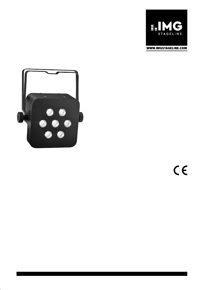
DMX-LED-Scheinwerfer
DMX LED Spotlight
PARL-174DMX
Bestell-Nr. • Order No. 38.6310
BEDIENUNGSANLEITUNG
INSTRUCTION MANUAL
MODE D’EMPLOI
ISTRUZIONI PER L’USO
MANUAL DE INSTRUCCIONES
VEILIGHEIDSVOORSCHRIFTEN
ŚRODKI BEZPIECZEŃSTWA
SIKKERHEDSOPLYSNINGER
SÄKERHETSFÖRESKRIFTER
TURVALLISUUDESTA
ELECTRONICS FOR SPECIALISTS ELECTRONICS FOR SPECIALISTS ELECTRONICS FOR SPECIALISTS ELECTRONICS FOR SPECIALISTS

Deutsch ..........Seite 4
English ...........Page 12
Français ..........Page 20
Italiano...........Pagina 28
Español ..........Página 36
Polski ............Strona 44
Nederlands .......Pagina 52
Dansk ............Sida 53
Svenska ..........Sidan 54
Suomi............Sivulta 55
ELECTRONICS FOR SPECIALISTS ELECTRONICS FOR SPECIALISTS ELECTRONICS FOR SPECIALISTS ELECTRONICS FOR SPECIALISTS
2
1
➀
➂
2
➁
DMX-512
3
21
MENU
ESC
ENTER
DMX OUT DMX IN
3 4 5 6 7 8 9
3
12
MIC
230V~/50 Hz
2
3
Inhalt
1 Übersicht . . . . . . . . . . . . . . . 4
2 Hinweise für den sicherenGebrauch . 4
Deutsch
3 Einsatzmöglichkeiten . . . . . . . . . 5
4 Montage . . . . . . . . . . . . . . . 5
5 Inbetriebnahme . . . . . . . . . . . .5
6 Bedienung. . . . . . . . . . . . . . . 6
7 Betrieb ohne DMX-Steuergerät . . . . 6
7.1 Automatikmodus . . . . . . . . . . . . 6
7.2 Musiksteuerung. . . . . . . . . . . . . 6
7.3 Farbstrahlerbetrieb . . . . . . . . . . . 6
7.4 Master / Slave-Betrieb . . . . . . . . . . 6
8 DMX-Steuerung . . . . . . . . . . . .7
8.1 Anschluss. . . . . . . . . . . . . . . . 7
8.2 Anzahl der DMX-Kanäle einstellen . . . . 7
8.3 Startadresse einstellen. . . . . . . . . . 7
8.4 Unteradressen verwenden . . . . . . . .8
9 Weitere Funktionen . . . . . . . . . .8
9.1 Display-Abschaltung. . . . . . . . . . .8
9.2 Farbbalance / Weißabgleich. . . . . . . .8
9.3 Tastensperre . . . . . . . . . . . . . . 9
9.4 Anzeige der Firmware-Version . . . . . . 9
10 Technische Daten . . . . . . . . . . . 9
10.1 DMX-Funktionen . . . . . . . . . . . . 9
10.1.1 3-Kanal-Modus (HSV) . . . . . . . . . 9
10.1.2 4-Kanal-Modus . . . . . . . . . . . .9
10.1.3 5-Kanal-Modus . . . . . . . . . . . .9
10.1.4 6-Kanal-Modus . . . . . . . . . . . 10
10.1.5 8-Kanal-Modus . . . . . . . . . . . 10
10.2 Menüstruktur . . . . . . . . . . . . . 11
4
DMX-LED-Scheinwerfer
Diese Anleitung richtet sich an den Installateur des
Geräts und an den Bediener mit Grundkenntnissen
in der DMX-Steuerung. Bitte lesen Sie die Anleitung
vor dem Betrieb gründlich durch und heben Sie sie
für ein späteres Nachlesen auf.
Auf der ausklappbaren Seite 3 finden Sie alle
beschriebenen Bedienelemente und Anschlüsse.
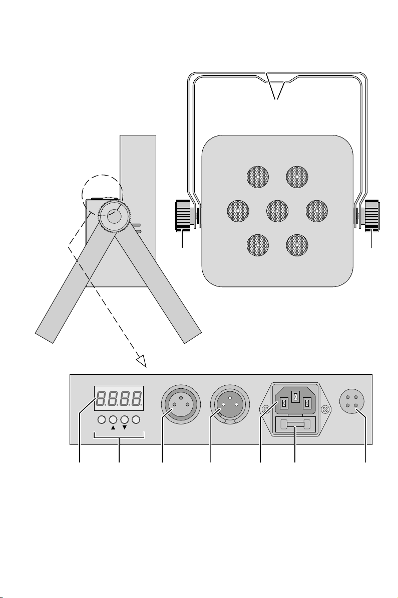
1 Übersicht
1 Montagebügel
2 Feststellschrauben für die Montagebügel
3 Display
4 Bedientasten
Taste MENU / ESC zum Verlassen eines Untermenüs
Tasten und zur Wahl eines Menüpunktes und
zum Ändern einer Einstellung im Menü
Taste ENTER zum Aufruf des Menüpunktes und
für den Weitersprung zum nächsten Parameter
5
DMX-Signal-Ausgang (3-pol. XLR) zum Anschluss
an den DMX-Eingang eines weiteren DMX-Lichteffektgerätes
Pin 1 = Masse, 2 = DMX−, 3 = DMX+
6 DMX-Signal-Eingang (3-pol. XLR) zum Anschluss
eines Lichtsteuergerätes
Pin 1 = Masse, 2 = DMX−, 3 = DMX+
7
Netzbuchse zum Anschluss an eine Steckdose
(230 V/ 50 Hz) über das beiliegende Netzkabel
8 Halterung für die Netzsicherung
Eine geschmolzene Sicherung nur durch eine gleichen Typs ersetzen.
9 Mikrofon zur Musiksteuerung
2 Hinweise für den
sicherenGebrauch
Der Scheinwerfer entspricht allen relevanten Richtlinien der EU und trägt deshalb das -Zeichen.
WARNUNG
Verwenden Sie den Scheinwerfer nur im Innen-
•
bereich und schützen Sie ihn vor Tropf- und
Spritzwasser sowie vor hoher Luftfeuchtigkeit.
Der zulässige Einsatztemperaturbereich beträgt
0 – 40 °C.
Der Scheinwerfer wird mit lebensgefährlicher Netzspannung versorgt.
Nehmen Sie deshalb niemals selbst
Eingriffe am Gerät vor und stecken
Sie nichts in die Lüftungsöffnungen.
Es besteht die Gefahr eines elektrischen Schlags.
Stellen Sie keine mit Flüssigkeit gefüllten Gefäße,
•
z. B. Trinkgläser, auf den Scheinwerfer.
Die im Scheinwerfer entstehende Wärme muss
•
durch Luftzirkulation abgegeben werden. Decken
Sie die Lüftungsöffnungen am Gehäuse nicht ab.
Nehmen Sie den Scheinwerfer nicht in Betrieb
•
oder ziehen Sie sofort den Netzstecker aus der
Steckdose,
1.
wenn sichtbare Schäden am Scheinwerfer oder
am Netzkabel vorhanden sind,
2. wenn nach einem Sturz oder Ähnlichem der
Verdacht auf einen Defekt besteht,
3. wenn Funktionsstörungen auftreten.
Geben Sie den Scheinwerfer in jedem Fall zur
Reparatur in eine Fachwerkstatt.
Ziehen Sie den Netzstecker nie am Kabel aus der
•
Steckdose, fassen Sie immer am Stecker an.
Verwenden Sie für die Reinigung nur ein trocke-
•
nes, weiches Tuch, niemals Wasser oder Chemikalien.
Wird der Scheinwerfer zweckentfremdet, nicht
•
sicher montiert, nicht richtig angeschlossen,
falsch bedient oder nicht fachgerecht repariert,
kann keine Haftung für daraus resultierende
Sach- oder Personenschäden und keine Garantie
für das Gerät übernommen werden.
Soll der Scheinwerfer endgültig aus dem
Betrieb genommen werden, übergeben Sie
ihn zur umweltgerechten Entsorgung einem
örtlichen Recyclingbetrieb.
3 Einsatzmöglichkeiten
Dieser flache LED-Scheinwerfer dient zur Beleuchtung z. B. auf Bühnen, in Diskotheken und Festsälen.
Als Lichtquelle sind 7 superhelle 8-W-RGBW-LEDs
eingesetzt. Diese haben im Vergleich zu Glühlampen einen niedrigen Stromverbrauch, eine geringe
Wärmeentwicklung und eine lange Lebensdauer.
Mit den LEDs kann farbiges Licht in den drei Grundfarben (Rot, Grün und Blau) und Weiß abgestrahlt
werden sowie daraus generierte Mischfarben.
Außerdem sind Farbüberblendungen und Stroboskop-Effekte möglich.
Der Scheinwerfer ist für die Steuerung über ein
DMX-Lichtsteuergerät ausgelegt (3, 4, 5, 6 oder 8
DMX- Steuerkanäle wählbar). Er kann aber auch
allein oder im Verbund mehrerer PARL-174DMX
(Master- /Slave-Modus) betrieben werden. Zusätzlich
sorgt das integrierte Mikrofon für musiksynchrone
Effekte.
4 Montage
Platzieren Sie das Gerät immer so, dass im Betrieb
eine ausreichende Luftzirkulation gewährleistet ist.
Die Lüftungsöffnungen am Gehäuse dürfen auf
keinen Fall abgedeckt werden.
WARNUNG Der Scheinwerfer muss fachgerecht
und sicher montiert werden. Wird
er an einer Stelle installiert, unter
der sich Personen aufhalten können,
muss er zusätzlich gesichert werden (z. B. durch ein
Fangseil am Montagebügel; das Fangseil so befestigen, dass der Fallweg des Gerätes nicht mehr als
20 cm betragen kann).
1. Den Scheinwerfer über einen Montagebügel
(1) befestigen, z. B. mit einer stabilen Monta
geschraube oder einer Lichtstrahler-Halterung
(C-Haken) an einer Traverse.
Zum Ausrichten des Scheinwerfers die zwei
Feststellschrauben (2) am Montagebügel lösen.
Die gewünschte Neigung des Scheinwerfers einstellen und die Schrauben wieder fest anziehen.
2. Alternativ lässt sich der Scheinwerfer auch frei
aufstellen (Abb. 1). Dazu die Montagebügel so
unter dem Scheinwerfer spreizen, dass sie als
Ständer dienen. Die Feststellschrauben anschließend fest anziehen.
5 Inbetriebnahme
WARNUNG
Blicken Sie nicht für längere Zeit
direkt in die Lichtquelle, das kann
zu Augenschäden führen.
Beachten Sie, dass sehr schnelle Lichtwechsel bei
Epileptikern und bei fotosensiblen Menschen epileptische Anfälle auslösen können!
Das beiliegende Netzkabel zuerst in die Netzbuchse
(7) stecken und dann in eine Steckdose (230 V/ 50 Hz).
Danach ist das Gerät betriebsbereit und lässt sich
über ein DMX-Lichtsteuergerät bedienen (☞ Kap.8)
oder führt eigenständig das eingestellte Steuerungsprogramm aus (☞ Kap. 7). Zum Ausschalten den
Netzstecker aus der Steckdose ziehen.
Um einen besseren Bedienkomfort zu erhalten,
ist es empfehlenswert, das Gerät an eine Steckdose
anzuschließen, die sich über einen Lichtschalter einund ausschalten lässt.
Vorsicht: Das Gerät darf nicht über einen Dimmer
an die Netzspannung angeschlossen werden!
Das Gerät verfügt über einen Überhitzungsschutz.
Dadurch schaltet es sich bei zu hoher Temperatur ab
und nach dem Abkühlen automatisch wieder ein.
Deutsch
-
5
6 Bedienung
Die Geräteeinstellungen werden über ein Systemmenü durchgeführt, das sich mithilfe der Tasten
(4) und des Displays (3) bedienen lässt. Nach dem
Deutsch
Einschalten der Stromversorgung zeigt das Display
jeweils die zuletzt vorgenommene Einstellung.
Die Tasten haben folgende Funktionen:
– Taste MENU / ESC für den Rücksprung auf die über-
geordnete Menüebene
– Tasten und für die Auswahl eines Menü-
punktes und zum Einstellen von Werten oder
Menüoptionen
– Taste ENTER zum Aufruf des Menüpunktes und
für den Weitersprung zum nächsten Parameter
Die Menüstruktur ist auf der Seite 11
Anhand der Kapitel 7 bis 9 mit den Tasten die
gewünschten Einstellungen für den jeweiligen
Betriebsmodus vornehmen.
Wichtig: Damit eine Einstellung im Gerät gespeichert wird, sodass sie auch nach dem Wiedereinschalten der Stromversorgung bestehen bleibt,
ein Untermenü erst 10 s nach der Änderung einer
Einstellung verlassen. (Beim Speichern flackert das
Display kurz. Ist die Display-Abschaltung eingeschaltet [☞ Kap. 9.1], erlischt es.)
dargestellt.
7 Betrieb ohne DMX-Steuergerät
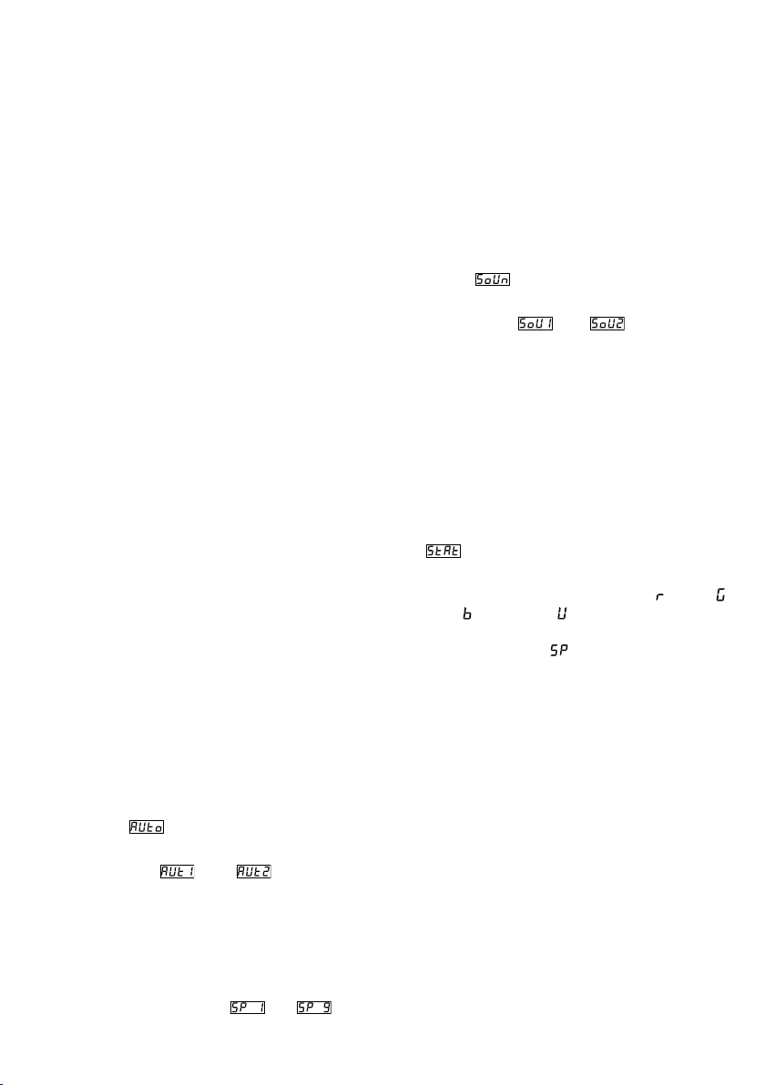
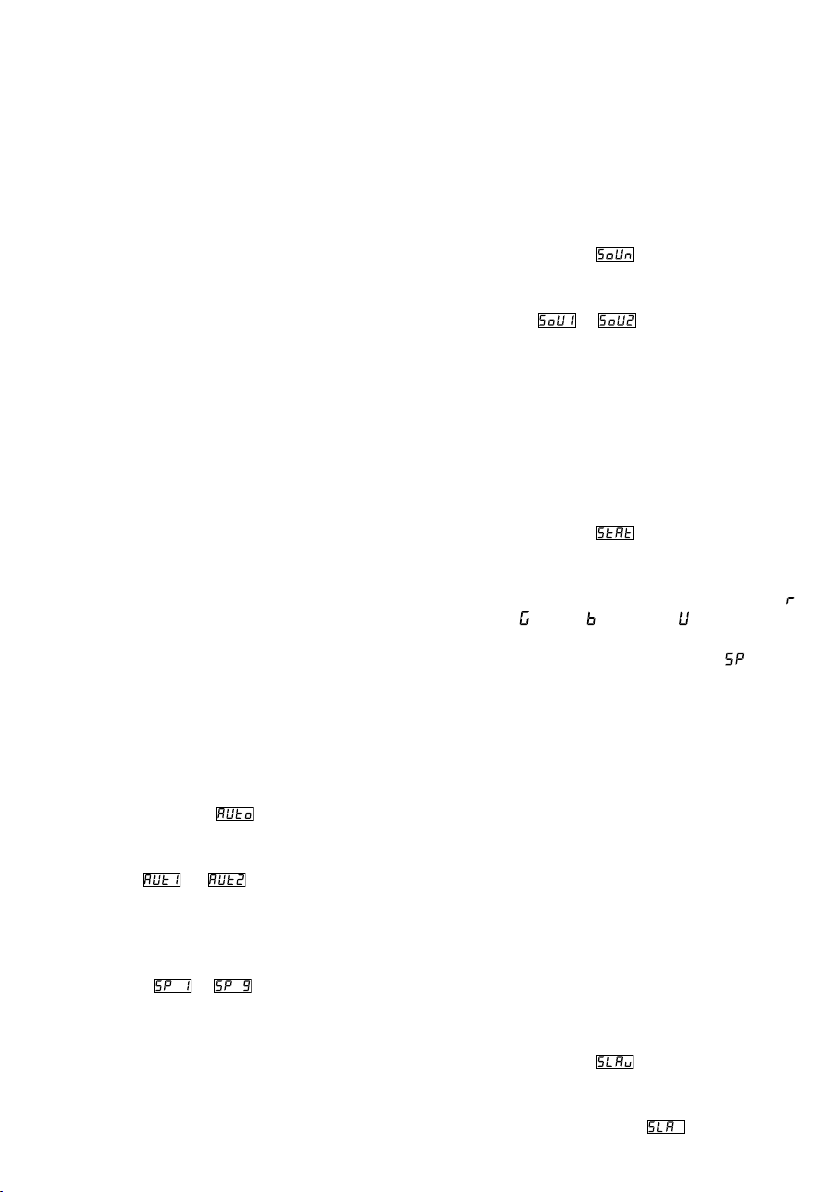
7.1 Automatikmodus
Das Gerät verfügt über zwei automatisch ablaufende Show-Programme.
„Auto 1“: Farbfolge mit Überblendungen
„Auto 2“: Stroboskop
Zum Aufruf eines dieser Programme:
1)
Die Taste MENU / ESC so oft drücken, bis das
Hauptmenü erreicht ist.
2)
Mit der Taste oder im Hauptmenü die
Option wählen.
3)
Die Taste ENTER drücken: Das zuletzt eingestellte
Programm ( oder ) ist aktiviert und
wird im Display angezeigt. Mit der Taste oder
aus den beiden Programmen das gewünschte
auswählen.
4)
Um die Geschwindigkeit zu ändern, die Taste
ENTER drücken: Die aktuelle Geschwindigkeit
wird angezeigt. Mit der Taste oder aus den
9 Geschwindigkeiten bis die gewünschte auswählen.
6
7.2 Musiksteuerung
Soll der Scheinwerfer über sein Mikrofon (9) auf
Musik reagieren, kann zwischen zwei Musikmodi
gewählt werden:
„Sound 1“: schallgesteuertes, gleichzeitiges Auf-
blitzen aller LEDs
„Sound 2“: schallgesteuertes Aufblitzen mit wech-
selnden Farben
1)
Die Taste MENU / ESC so oft drücken, bis das
Hauptmenü erreicht ist.
2)
Mit der Taste oder im Hauptmenü die
Option wählen.
3)
Die Taste ENTER drücken: Der zuletzt eingestellte
Musikmodus ( oder ) ist aktiviert und
wird im Display angezeigt. Mit der Taste oder
aus den beiden Modi den gewünschten aus-
wählen.
7.3 Farbstrahlerbetrieb
Soll konstant eine Farbe abgestrahlt werden oder
diese als Stroboskop regelmäßig aufblitzen:
1)
Die Taste MENU / ESC so oft drücken, bis das
Hauptmenü erreicht ist.
2)
Mit der Taste oder im Hauptmenü die Option
wählen.
3)
Die Taste ENTER drücken. Das Display zeigt die
zuletzt eingestellte Grundfarbe Rot ( ), Grün ( ),
Blau ( ) oder Weiß ( ) und den dazugehörigen
Helligkeitswert. Die Blitzfrequenz für den Stroboskopbetrieb ist mit gekennzeichnet.
4) Mit der Taste oder die Helligkeit der angewählten Farbe oder Weiß für die gewünschte
Farbmischung einstellen (Anzeige 0 – 255). Die
Blitzfrequenz ist einstellbar zwischen 0 Hz (Dauerlicht) und ca. 20 Hz.
5)
Mit der Taste ENTER zwischen den Einstellungen
wechseln.
7.4 Master / Slave-Betrieb
Mehrere Geräte PARL-174DMX können synchron
betrieben werden. Dabei übernimmt das erste Gerät
(Master-Gerät) die Steuerung der übrigen Geräte
(Slave-Geräte). Die Geräte miteinander zu einer
Kette verbinden. Siehe dazu Kapitel 8.1, jedoch
ohne den Bedienschritt 1 zu beachten.
Das Master-Gerät auf Automatikmodus, Musiksteuerung oder Farbstrahlerbetrieb einstellen
(☞Kap. 7.1 – 7.3). Die Slave-Geräte folgendermaßen auf den Slave-Betrieb einstellen:
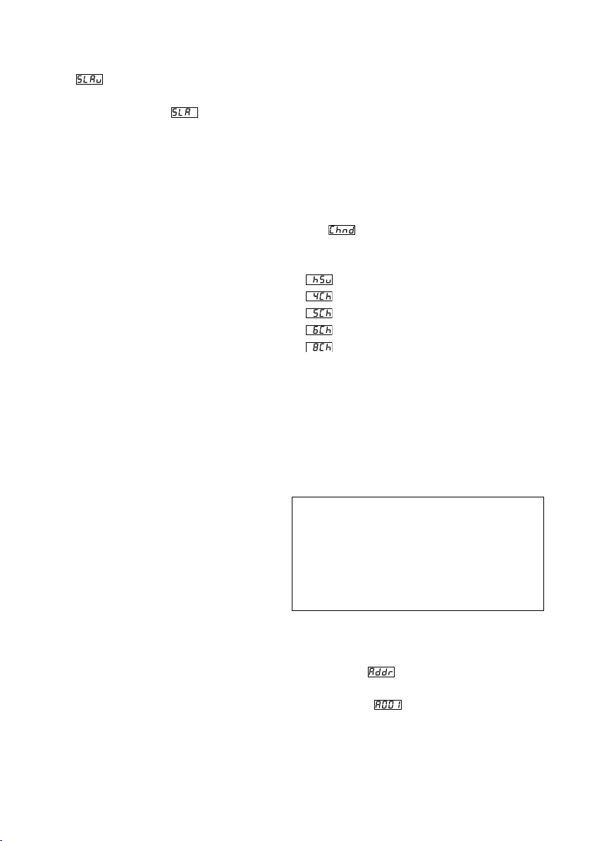
1)
Die Taste MENU / ESC so oft drücken, bis das
Hauptmenü erreicht ist.
2)
Mit der Taste oder im Hauptmenü die
Option wählen.
3)
Die Taste ENTER drücken: Der Slave-Betrieb ist
aktiviert, das Display zeigt .
8 DMX-Steuerung
DMX ist die Abkürzung für Digital Multiplex und
ermöglicht die digitale Steuerung von mehreren
DMX-Geräten über eine gemeinsame Steuerleitung.
Zur Bedienung über ein DMX-Lichtsteuergerät (z. B.
DMX-1440 oder DMX-510USB von IMG STAGELINE)
verfügt der LED-Scheinwerfer über 8 DMX-Steuerkanäle. Er lässt sich bei Bedarf aber auch über nur
6, 5, 4 oder 3 Kanäle steuern. Die Funktionen der
Kanäle und die entsprechenden DMX-Werte finden
Sie in Kapitel 10.1.
8.1 Anschluss
Als DMX-Schnittstelle besitzt das Gerät 3-polige
XLR-Anschlüsse mit folgender Kontaktbelegung:
Pin 1 = Masse, Pin 2 = DMX−, Pin 3 = DMX+
Für die DMX-Signalübertragung sollten spezielle
Kabel verwendet werden (z. B. Kabel der CDMXNSerie von IMG STAGELINE). Bei Leitungslängen ab
150 m oder bei der Steuerung von mehr als 32 Geräten über einen DMX-Ausgang wird grundsätzlich
das Zwischenschalten eines DMX-Aufholverstärkers
empfohlen (z. B. SR-103DMX).
1)
Den Steuereingang DMX IN (6) mit dem
DMX-Ausgang des Lichtsteuergerätes verbinden.
2)
Den Steuerausgang DMX OUT (5) mit dem Steuereingang DMX IN des nächsten DMX-gesteuerten
Gerätes verbinden. Dessen Ausgang wieder mit
dem Eingang des nachfolgenden Gerätes verbinden usw., bis alle DMX-gesteuerten Geräte
in einer Kette angeschlossen sind.
3)
Um Störungen bei der Signalübertragung auszuschließen, sollte bei langen Leitungen oder bei
einer Vielzahl von hintereinandergeschalteten
Geräten der Steuerausgang des letzten DMXGerätes der Kette mit einem 120-Ω-Widerstand
(>0,3 W) abgeschlossen werden: In die Ausgangsbuchse einen entsprechenden Abschlussstecker (z. B. DLT-123) stecken.
8.2 Anzahl der DMX-Kanäle einstellen
Die Anzahl der DMX-Kanäle hängt von den benötigten Funktionen ab und eventuell auch von
der Anzahl der verfügbaren Steuerkanäle am
Lichtsteuergerät. Im 8-Kanal-Betrieb lassen sich
verschiedene interne Show-Programme abrufen.
Zudem ist es mithilfe von Unteradressen möglich,
über nur 8 DMX-Kanäle bis zu 66 PARL-174DMX
individuell zu steuern. Zum Auswählen der Anzahl
der DMX-Kanäle:
1)
Die Taste MENU / ESC so oft drücken, bis das
Hauptmenü erreicht ist.
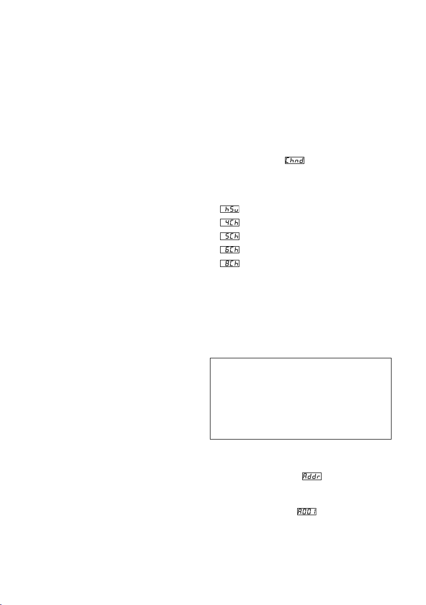
2) Mit der Taste oder im Hauptmenü die Option wählen.
3)
Die Taste ENTER drücken: Der aktuell eingestellte
Kanalmodus wird angezeigt:
= 3-Kanal-Betrieb (HSV-Farbraum)
= 4-Kanal-Betrieb
= 5-Kanal-Betrieb
= 6-Kanal-Betrieb
= 8-Kanal-Betrieb
4) Mit der Taste oder die gewünschte Option
auswählen.
8.3 Startadresse einstellen
Damit der Scheinwerfer angesteuert werden kann,
muss eine DMX-Startadresse für den 1. DMX- Kanal
eingestellt werden. Die folgenden DMX-Kanäle sind
dann automatisch den folgenden Adressen zugeordnet.
Beispiel: Bei Startadresse 5 für den Kanal 1
– sind im 4-Kanal-Modus die Kanäle 2 bis 4 den
Adressen 6 bis 8 zugeordnet; die Adresse 9 ist die
nächstmögliche freie Startadresse für das folgende
DMX-gesteuerte Gerät.
– sind im 8-Kanal-Modus die Kanäle 2 bis 8 den Ad-
ressen 6 bis 12 zugeordnet; die Adresse 13 ist die
nächstmögliche freie Startadresse für das folgende
DMX-gesteuerte Gerät.
1)
Die Taste MENU / ESC so oft drücken, bis das
Hauptmenü erreicht ist.
2)
Mit der Taste oder im Hauptmenü den
Menüpunkt wählen.
3)
Die Taste ENTER drücken: Die aktuell eingestellte
Adresse, z. B. , wird angezeigt.
4) Mit der Taste oder die gewünschte Adresse
einstellen.
Nach dem Einstellen der Startadresse lässt sich der
Scheinwerfer über das DMX-Steuergerät bedienen.
Der Empfang von Steuersignalen wird durch einen
blinkenden Punkt im Display angezeigt.
Deutsch
7
8.4 Unteradressen verwenden
Durch die Verwendung von Unteradressen lassen
sich über eine einzige DMX-Startadresse bis zu
66 Scheinwerfer(gruppen) unabhängig voneinan-
Deutsch
der steuern. Die maximal mögliche Anzahl DMXgesteuerter Geräte wird dadurch erheblich erhöht.
Die Anwahl von Scheinwerfern mit einer Unteradresse erfolgt über den DMX-Kanal 8 (☞Tabelle
„Unteradressen für den 8-Kanal-Modus“, Kapitel
10.1.5). Alle Scheinwerfer mit einer Unteradresse
lassen sich auch synchron steuern, wenn der
DMX-Kanal 8 auf einen DMX-Wert von kleiner als
10 eingestellt wird.
1)
Die Taste MENU / ESC so oft drücken, bis das
Hauptmenü erreicht ist.
2)
Mit der Taste oder im Hauptmenü den
Menüpunkt wählen.
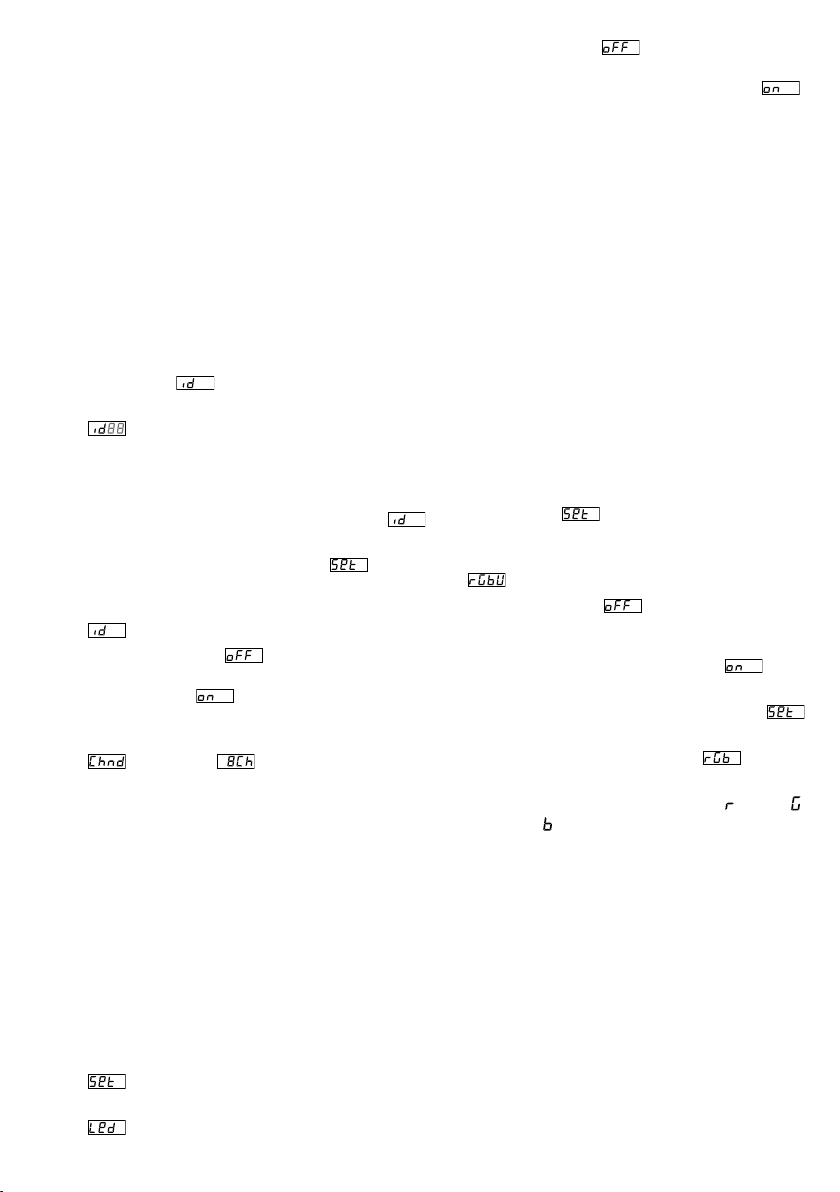
3) Die Taste ENTER drücken. Das Display zeigt jetzt
und eine Zahl zwischen 01 und 66.
4) Mit der Taste oder die gewünschte Unter-
adresse einstellen.
5)
Über die Taste MENU / ESC ins Hauptmenü zurückkehren, sodass das Display wieder nur
anzeigt.
6) Mit der Taste den Menüpunkt wählen
und mit der Taste ENTER aufrufen.
7)
Mit der Taste oder den Untermenüpunkt
wählen und mit der Taste ENTER aufrufen.
8)
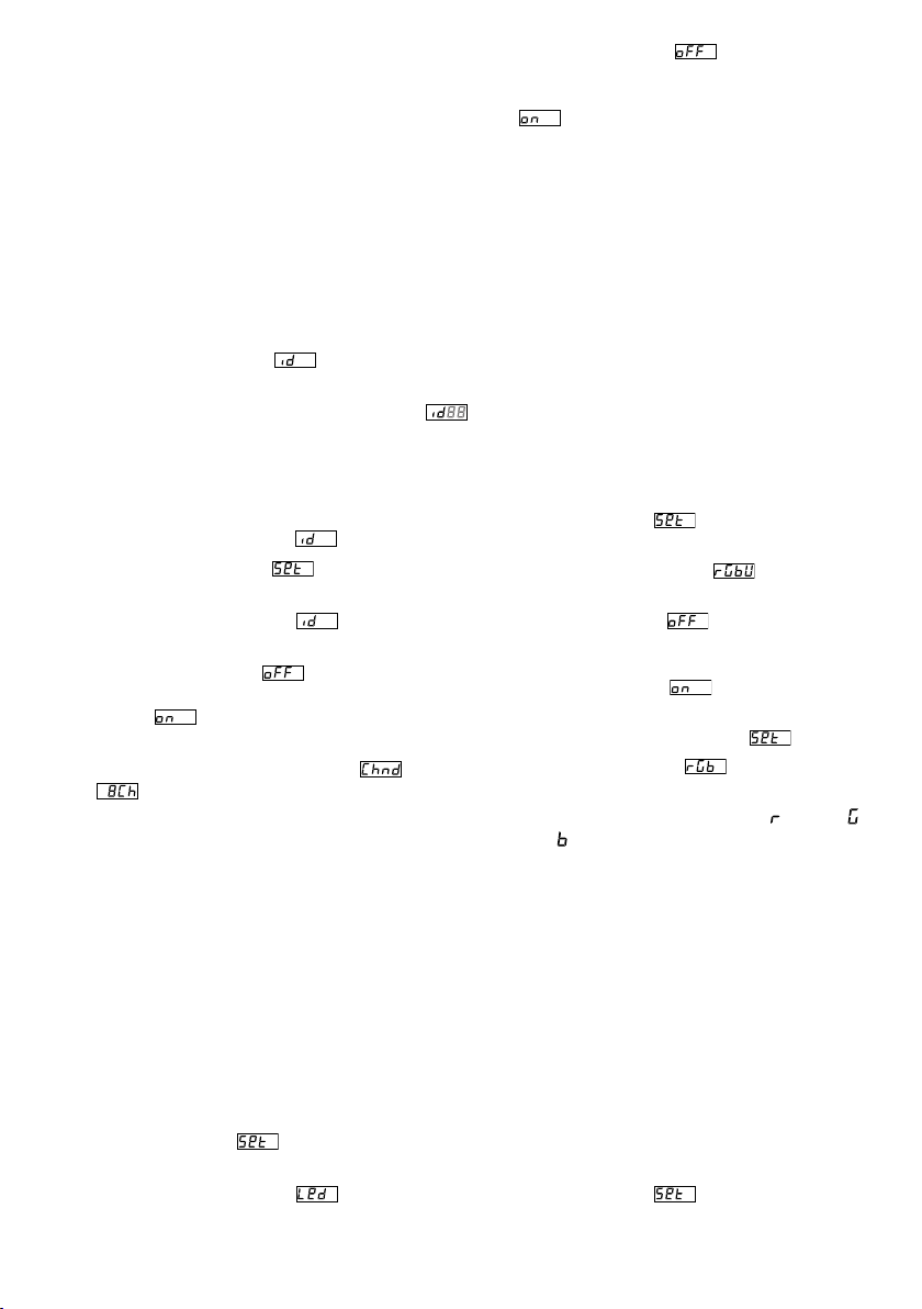
Wenn das Display zeigt, d. h. die Unteradressierung ausgeschaltet ist, diese mit der Taste
einschalten ( ).
9)
Den Scheinwerfer für die Steuerung über 8 DMXKanäle einstellen, ☞ Kapitel 8.2 (Menüpunkt
, Einstellung ).
Um den Scheinwerfer bedienen zu können, am
Lichtsteuergerät den DMX-Kanal 8 auf den DMXWert stellen, welcher der Unteradresse des Scheinwerfers entspricht (☞ Tabelle „Unteradressen für
den 8-Kanal-Modus“, Kapitel 10.1.5).
9 Weitere Funktionen
9.1 Display-Abschaltung
Soll das Display (3) im Betrieb dunkel sein, die automatische Display-Abschaltung einschalten:
1)
Die Taste MENU / ESC so oft drücken, bis das
Hauptmenü erreicht ist.
2)
Mit der Taste oder im Hauptmenü die Option
wählen und mit der Taste ENTER aufrufen.
3)
Mit der Taste oder den Untermenüpunkt
wählen und mit der Taste ENTER aufrufen.
8
4) Wenn das Display zeigt, ist die Abschaltfunktion ausgeschaltet, d. h. das Display leuchtet immer. Bei eingeschalteter Funktion ( )
erlischt das Display einige Sekunden nach dem
letzten Tastendruck und wird beim nächsten
Tasten druck wieder eingeschaltet. Mit der Taste
oder die gewünschte Option wählen.
9.2 Farbbalance / Weißabgleich
Die Balance zwischen den drei Grundfarben Rot,
Grün und Blau kann verschoben werden, wodurch
sich auch die Lichtfarbe bei kombiniertem weißen
Licht ändert (wenn die drei Farben zusätzlich zu den
weißen LEDs verwendet werden). Damit lassen sich
z. B. Unterschiede zu anderen Scheinwerfern ausgleichen, wenn der LED-Scheinwerfer gemeinsam
mit diesen gesteuert wird.
Zum Einschalten der Farbbalance-Funktion und Einstellen der Korrekturwerte:
1)
Die Taste MENU / ESC so oft drücken, bis das
Hauptmenü erreicht ist.
2)
Mit der Taste oder im Hauptmenü den
Menüpunkt
ENTER aufrufen.
3)
Mit der Taste oder den Untermenüpunkt
wählen und mit der Taste ENTER aufrufen.
4)
Wenn das Display zeigt, ist die Funktion
ausgeschaltet, d. h. die eingestellten Korrekturwerte werden nicht berücksichtigt. Mit der Taste
oder die Funktion einschalten ( ).
5)
Über die Taste MENU / ESC ins Hauptmenü zurückkehren, sodass das Display wieder
anzeigt.
6) Mit der Taste den Menüpunkt wählen.
7) Die Taste ENTER drücken. Das Display zeigt die
zuletzt eingestellte Grundfarbe, Rot ( ), Grün ( )
oder Blau ( ) und den dazugehörigen Korrekturwert (0 – 255). Dieser stellt die maximale Helligkeit
dar, die diese Farbe erreichen soll.
8) Mit der Taste oder den Wert für die angewählte Farbe einstellen.
9)
Mit der Taste ENTER zwischen den Farben wechseln.
wählen und mit der Taste
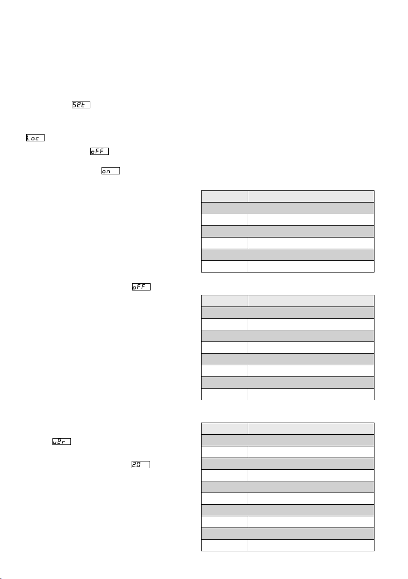
9.3 Tastensperre
Gegen eine unbeabsichtigte Bedienung kann die
Tastensperre eingeschaltet werden.
Tastensperre einschalten:
1)
Die Taste MENU / ESC so oft drücken, bis das
Hauptmenü erreicht ist.
2)
Mit der Taste oder im Hauptmenü den
Menüpunkt wählen und mit der Taste
ENTER aufrufen.
3)
Mit der Taste oder den Untermenüpunkt
wählen und mit der Taste ENTER aufrufen.
4)
Das Display zeigt , d. h. die Tastensperre
ist ausgeschaltet. Mit der Taste oder die
Funktion einschalten ( ). Nach ca. 10 s kann
der Scheinwerfer nicht mehr über die Tasten
MENU / ESC, und bedient werden.
Tastensperre ausschalten:
1) Die Taste ENTER zweimal drücken.
2)
Die Tastenfolge
drücken. Bei
jedem Tastendruck erscheint ein waagerechter
Strich auf dem Display.
3) Die Eingabe mit der Taste ENTER abschließen.
4)
Innerhalb von ca. 8 s mit der Taste oder
die Sperrfunktion ausschalten ( ). Wurde zu
lange gewartet, ist die Tastensperre wieder aktiv.
In diesem Fall die Bedienschritte wiederholen.
Hinweis: Bitte beachten Sie, dass bei aktiver Tastensperre
nach dem Aus- und Wiedereinschalten der Stromversorgung nicht automatisch die zuletzt gewählte Betriebsart
fortgesetzt wird.
9.4 Anzeige der Firmware-Version
Um die Versionsnummer der Firmware (Betriebssystem des Geräts) anzuzeigen:
1)
Die Taste MENU / ESC so oft drücken, bis das
Hauptmenü erreicht ist.
2)
Mit der Taste oder im Hauptmenü die
Option wählen.
3)
Die Taste ENTER drücken: Im Display wird die
aktuelle Versionsnummer (z. B. ) angezeigt.
10 Technische Daten
Datenprotokoll: . . . . . . . . . DMX 512
Anzahl der DMX-Kanäle:
Stromversorgung:
Leistungsaufnahme: . . . . . max. 70 VA
Leuchtmittel: . . . . . . . . . . . 7 × 8-W-RGBW-LEDs
Abstrahlwinkel:
. . . . . . . . . 40°
Einsatztemperatur:
Abmessungen: . . . . . . . . . 240 × 190 × 80 mm
Gewicht: . . . . . . . . . . . . . . 2 kg
10.1 DMX-Funktionen
10.1.1 3-Kanal-Modus (HSV)
DMX-Wert Funktion
Kanal 1: Farbton (Hue)
0 – 255 Farbton
Kanal 2: Farbsättigung (Saturation)
0 – 255 Farbsättigung
Kanal 3: Helligkeitswert (Value)
0 – 255 Helligkeit
10.1.2 4-Kanal-Modus
DMX-Wert Funktion
Kanal 1: Rot-Anteil
0 – 255 Helligkeit Rot
Kanal 2: Grün-Anteil
0 – 255 Helligkeit Grün
Kanal 3: Blau-Anteil
0 – 255 Helligkeit Blau
Kanal 4: Weiß-Anteil
0 – 255 Helligkeit Weiß
10.1.3 5-Kanal-Modus
DMX-Wert Funktion
Kanal 1: Dimmer
0 – 255 Gesamthelligkeit
Kanal 2: Rot-Anteil
0 – 255 Helligkeit Rot
Kanal 3: Grün-Anteil
0 – 255 Helligkeit Grün
Kanal 4: Blau-Anteil
0 – 255 Helligkeit Blau
Kanal 5: Weiß-Anteil
0 – 255 Helligkeit Weiß
. . 3, 4, 5, 6 oder 8
. . . . . . . 230 V/ 50 Hz
. . . . . . 0 – 40 °C
Deutsch
9
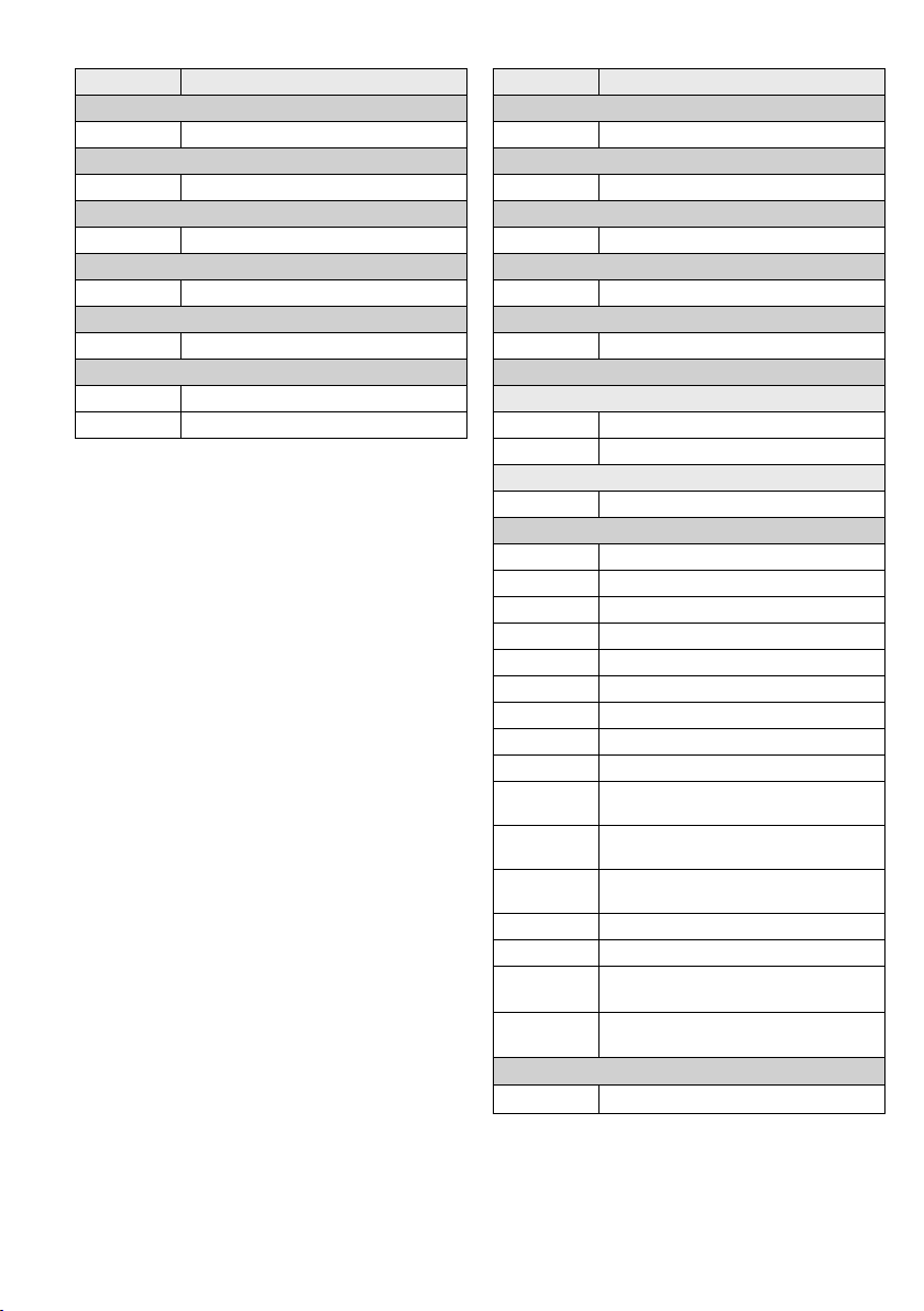
10.1.4 6-Kanal-Modus
DMX-Wert Funktion
Kanal 1: Dimmer
Deutsch
0 – 255 Gesamthelligkeit
Kanal 2: Rot-Anteil
0 – 255 Helligkeit Rot
Kanal 3: Grün-Anteil
0 – 255 Helligkeit Grün
Kanal 4: Blau-Anteil
0 – 255 Helligkeit Blau
Kanal 5: Weiß-Anteil
0 – 255 Helligkeit Weiß
Kanal 6: Stroboskop
0 – 9 kein Stroboskop
10 – 255 Stroboskop langsam schnell
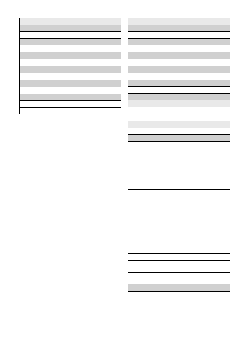
10.1.5 8-Kanal-Modus
DMX-Wert Funktion
Kanal 1: Dimmer
0 – 255 Gesamthelligkeit
Kanal 2: Rot-Anteil
0 – 255 Helligkeit Rot
Kanal 3: Grün-Anteil
0 – 255 Helligkeit Grün
Kanal 4: Blau-Anteil
0 – 255 Helligkeit Blau
Kanal 5: Weiß-Anteil
0 – 255 Helligkeit Weiß
Kanal 6: Stroboskop, Ablaufgeschwindigkeit
wenn Kanal 7 = 0 – 15:
0 – 9 kein Stroboskop
10 – 255 Stroboskop langsam schnell
wenn Kanal 7 = 16 – 223:
0 – 255 Programmablauf: langsam schnell
Kanal 7: Show-Programme
0 – 15 kein Programm
16 – 31 Farbfolge mit Überblendungen 1
32 – 47 Farbfolge mit Überblendungen 2
48 – 63 Farbfolge mit Überblendungen 3
64 – 79 Farbfolge mit Überblendungen 4
80 – 95 Farbfolge mit Überblendungen 5
96 – 111 Stroboskop Weiß + Rot + Grün + Blau
112 – 127 Farbfolge mit Ein- und Ausblenden 1
128 – 143 Farbfolge mit abrupten Wechseln
144 – 159
160 – 175
176 – 191
192 – 207 Farbfolge mit Ein- und Ausblenden 2
208 – 223 Farbfolge mit Überblendungen 6
224 – 239
240 – 255
Kanal 8: Unteradressierung wenn ID = ON
0 – 255
Farbfolge mit abrupten Wechseln
und Dunkelphasen
Farbfolge mit Einschalten
und Ausblenden
Farbfolge mit Einblenden
und Ausschalten
musiksynchrones Blitzen
Weiß + Rot + Grün + Blau
musiksynchrones Blitzen
mit wechselnden Farben
Unteradressen (☞ nächste Seite)
10
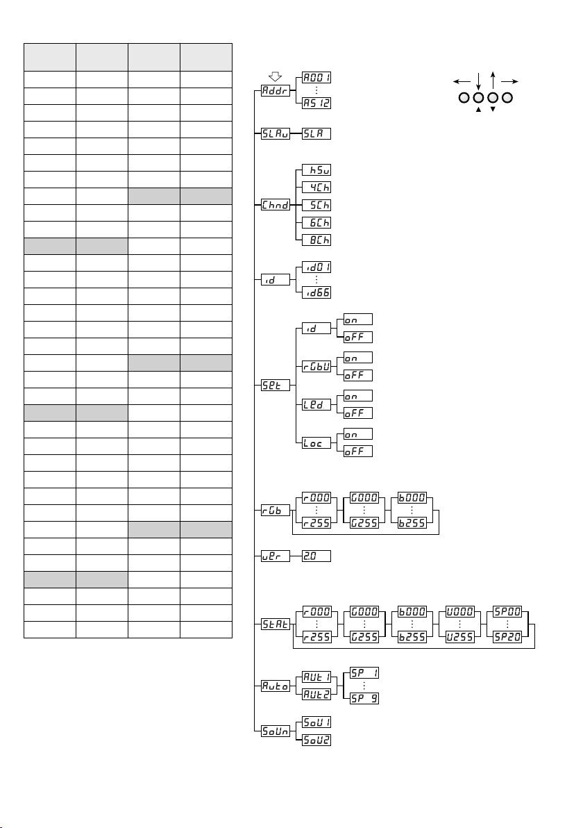
Unteradressen für den 8-Kanal-Modus
Unter-
adresse
alle
10
11
12
13
14
15
16
17
18
19
20
21 210 54 243
22 211 55 244
23 212 56 245
24 213 57 246
25 214 58 247
26 215 59 248
27 216 60 249
28 217 61 250
29 218 62 251
30 219 63 252
31 220 64 253
32 221 65 254
33 222 66 255
DMX-
Wert
000 – 009
1 010 – 019 34 223
2
020 – 029 35 224
3
020 – 039 36 225
4
040 – 049 37 226
5
050 – 059 38 227
6
060 – 069 39 228
7
070 – 079 40 229
8
080 – 089 41 230
9
090 – 099 42 231
100 – 109 43 232
110 – 119 44 233
120 – 129 45 234
130 – 139 46 235
140 – 149 47 236
150 – 159 48 237
160 – 169 49 238
170 – 179 50 239
180 – 189 51 240
190 – 199 52 241
200 – 209 53 242
Unter-
adresse
DMX-
Wert
10.2 Menüstruktur
Hauptmenü
DMX-Adresse
1 – 512
Slave-Betrieb
Anzahl der DMX-Kanäle
3 Kanäle (HSV)
4 Kanäle
5 Kanäle
6 Kanäle
8 Kanäle
Unteradressen (ID)
ID 1 – ID 66
Farbbalance
Rot
Rot Grün Blau Weiß
Grün Blau
Firmware-Version
Farbstrahlerbetrieb
MENU
− ein
Unteradressen (ID)
− aus
− ein
Farbbalance
− aus
− ein
Display-Abschaltung
− aus
− ein
Tastensperre
− aus
(max. Helligkeit)
ESC
Deutsch
ENTER
Blitz-
frequenz
Automatikbetrieb
Auto 1 / Auto 2
Geschwindigkeit 1 – 9
Änderungen vorbehalten.
Musiksteuerung
Sound 1 / Sound 2
Diese Bedienungsanleitung ist urheberrechtlich für MONACOR ® INTERNATIONAL GmbH & Co. KG geschützt.
Eine Reproduktion für eigene kommerzielle Zwecke – auch auszugsweise – ist untersagt.
11
Contents
1 Operating Elements and Connections 12
English
2 Safety Notes. . . . . . . . . . . . . 12
3 Applications . . . . . . . . . . . . . 13
4 Installation . . . . . . . . . . . . . 13
5 Setting the Spotlight intoOperation 13
6 Operation . . . . . . . . . . . . . . 14
7 Operation withoutDMXController . 14
7.1 Automatic mode . . . . . . . . . . . 14
7.2 Music control . . . . . . . . . . . . . 14
7.3 Floodlight mode . . . . . . . . . . . 14
7.4 Master / Slave mode . . . . . . . . . . 14
8 DMX Control . . . . . . . . . . . . 15
8.1 Connection . . . . . . . . . . . . . . 15
8.2 Setting the number of DMXchannels . 15
8.3 Setting the start address . . . . . . . . 15
8.4 Using sub-addresses. . . . . . . . . . 16
9 Additional Functions . . . . . . . . 16
9.1 Auto-off feature for the display . . . . 16
9.2 Colour balance / white balance . . . . . 16
9.3 Key lock . . . . . . . . . . . . . . . 16
9.4 Indication of firmware version . . . . . 17
10 Specifications . . . . . . . . . . . . 17
10.1 DMX functions . . . . . . . . . . . . 17
10.1.1 3-channel mode (HSV) . . . . . . . 17
10.1.2 4-channel mode . . . . . . . . . . 17
10.1.3 5-channel mode . . . . . . . . . . 17
10.1.4 6-channel mode . . . . . . . . . . 18
10.1.5 8-channel mode . . . . . . . . . . 18
10.2 Menu structure . . . . . . . . . . . . 19
DMX LED Spotlight
These instructions are intended for installers of the
unit and for users with basic knowledge in DMX
control. Please read the instructions carefully prior
to operation and keep them for later reference.
All operating elements and connections
described can be found on the fold-out page3.
1 Operating Elements and
Connections
1 Mounting brackets
2 Locking screws for the mounting brackets
3 Display
4 Control buttons
Button MENU / ESC to exit a submenu
Buttons and to select a menu item and to
change a setting in the menu
Button ENTER to activate the menu item and to
go to the next parameter
5 DMX signal output (3-pole, XLR) to connect the
DMX input of another DMX light effect unit;
Pin 1 = ground, 2 = DMX−, 3 = DMX+
6 DMX signal input (3-pole, XLR) to connect a light
controller;
Pin 1 = ground, 2 = DMX−, 3 = DMX+
7
Mains jack for connection to a socket (230 V/ 50 Hz)
via the mains cable provided
8 Support for the mains fuse
Always replace a blown fuse by one of the same
type.
9 Microphone for music control
2 Safety Notes
The spotlight corresponds to all relevant directives
of the EU and is therefore marked with
WARNING
The spotlight is suitable for indoor use only. Pro-
•
tect it against dripping water and splash water,
high air humidity and heat (admissible ambient
temperature range: 0 – 40 °C).
Do not place any vessel filled with liquid on the
•
unit, e. g. a drinking glass.
The spotlight uses dangerous mains
voltage. Leave servicing to skilled personnel only and do not insert anything
into the air vents; inexpert handling
may result in electric shock.
.
12
The heat generated inside the spotlight must be
•
dissipated by air circulation; never cover the air
vents of the housing.
Do not operate the spotlight or immediately dis-
•
connect the mains plug from the socket
1.
if the spotlight or the mains cable is visibly
damaged,
2.
if a defect might have occurred after the
spotlight was dropped or suffered a similar
accident,
3. if malfunctions occur.
In any case the spotlight must be repaired by
skilled personnel.
Never pull the mains cable to disconnect the
•
mains plug from the socket, always seize the
plug.
For cleaning only use a dry, soft cloth; never use
•
water or chemicals.
No guarantee claims for the spotlight and no
•
liability for any resulting personal damage or material damage will be accepted if the spotlight is
used for other purposes than originally intended,
if it is not safely installed or not correctly connected or operated, or if it is not repaired in an
expert way.
If the spotlight is to be put out of operation
definitively, take it to a local recycling plant
for a disposal which is not harmful to the
environment.
3 Applications
This flat LED spotlight is used for illumination, e. g.
on stage, in clubs and ballrooms. As a light source,
seven extra bright 8 W RGBW LEDs are used. Compared to incandescence lamps, they feature a low
power consumption, a low heat generation and a
long life. The LEDs are able to emit coloured light in
the three primary colours (red, green and blue) and
white light, but also light created by additive colour
mixing. Crossfading from one colour to another and
stroboscope effects are also possible.
The unit is designed for control via a DMX light
controller (3, 4, 5, 6 or 8 DMX control channels
available), but it is also possible to operate it on its
own or in combination with several PARL-174DMX
spotlights (master / slave mode). In addition, the integrated microphone provides effects in sync with
the music.
4 Installation
When placing the unit, always ensure a sufficient
air circulation during operation. Never cover the air
vents of the housing.
WARNING
rope at the mounting bracket; fix the safety rope so
that the maximum falling distance of the unit will
not exceed 20 cm).
1. Fasten the spotlight via a mounting bracket (1),
e. g. with a stable mounting screw or a support
for lighting units (C-hook) on a crossbar.
ing screws (2) on the mounting bracket, adjust
the desired inclination of the spotlight, then
retighten the screws.
2. Alternatively, place the spotlight as desired
(fig.1). Use the mounting brackets as a stand;
position them under the spotlight so that they
will support it. Then fasten the locking screws.
Install the spotlight safely and expertly. If it is installed at a place where
people may walk or sit under, it must
additionally be secured (e. g. by a safty
To adjust the spotlight, release the two lock-
5 Setting the Spotlight
intoOperation
WARNING
Never look directly into the light
source for a longer time, this may
cause eye damage.
Please note that fast changes in lighting may trigger epileptic seizures with photosensitive persons
or persons with epilepsy!
Connect the mains cable provided to the mains jack
(7) first, then connect it to a socket (230 V/ 50 Hz).
Thus, the spotlight is ready for operation. Operate
it via a DMX light controller (☞ chapter 8) or on its
own using the automatic control program adjusted
(☞ chapter 7). To switch off, disconnect the mains
plug from the socket.
For a more convenient operation, it is recommended to connect the unit to a mains socket which
is switched on and off via a light switch.
Caution: Never connect the unit to the mains volt-
age via a dimmer!
The unit is protected against overheating; it will
automatically switch off when the temperature is
too high and switch on again after cooling down.
English
13
6 Operation
The settings of the spotlight are made via a system
menu to be operated via the buttons (4) and the
English
display (3). After switching on the power supply,
the display shows the last setting made.
The buttons have the following functions:
– Button MENU / ESC to return to the higher menu
level
– Buttons and to select a menu item and to
set values or menu options
– Button ENTER to activate the menu item and to
go to the next parameter
The menu structure can be found on page 19
Use the buttons to make the desired settings for
the corresponding operating mode according to
chapters 7 to 9.
Important: To make sure that a setting has been
saved and is available when the power supply is
switched on again, wait for 10 seconds after making
the setting before exiting the submenu. (When the
setting is being saved, the display will briefly flicker.
If the auto-off feature for the display has been activated [☞ chapter9.1], it will go dark.)
7 Operation
withoutDMXController
7.1 Automatic mode
The unit offers two automatic show programs.
“Auto 1”: colour sequence with crossfading
“Auto 2”: stroboscope
To activate one of these programs:
1)
Press the button MENU / ESC repeatedly until you
enter the main menu.
2) Select the option in the main menu with
the button or .
3)
Press the button ENTER: The last program adjusted ( or ) is activated and shown
on the display. Select one of the two programs
with the button or .
4) To change the speed, press the button ENTER:
The current speed is shown. Select one of the
9speeds to with the button or .
14
7.2 Music control
For music control of the spotlight via its microphone
(9) two music modes are available:
“Sound 1”: all LEDs lighting up at the same time
by music control
“Sound 2”: LEDs lighting up with changing colours
by music control
1)
Press the button MENU / ESC repeatedly until you
enter the main menu.
2) Select the option in the main menu with
the button or .
3)
Press the button ENTER: The last music mode
.
adjusted ( or ) is activated and shown
on the display. Select one of the two modes with
the button or .
7.3 Floodlight mode
For radiating a single colour continuously or for
flashes of this colour at regular intervals (stroboscope):
1)
Press the button MENU / ESC repeatedly until you
enter the main menu.
2) Select the option in the main menu with
the button or .
Press the button ENTER: The display shows
the last primary colour adjusted, red ( ),
green ( ), blue ( ) or white ( ) and the corresponding brightness value. The flash rate for the
stroboscope mode is indicated with .
3)
Set the brightness of the selected colour or white
for the desired colour mixture (indication 0 – 255)
with the button or . The flash rate is adjustable between 0 Hz (permanent light) and
approx. 20 Hz.
4) To switch between different settings, press the
button ENTER.
7.4 Master / Slave mode
It is possible to operate several PARL-174DMX spotlights in sync. The first unit (master) will control the
other units (slaves). Connect the units in a chain;
see chapter 8.1, but skip step 1.
Set the master unit to automatic mode, music
control or floodlight mode (☞chapters 7.1 – 7.3).
Set the slave units to the slave mode as follows:
1)
Press the button MENU / ESC repeatedly until you
enter the main menu.
2) Select the option in the main menu with
the button or .
3) Press the button ENTER: The slave mode is acti-
vated; the display shows .
8 DMX Control
DMX is short for digital multiplex and allows digital
control of several DMX units via a common control
cable. For operation via a DMX light controller (e. g.
DMX-1440 or DMX-510USB from IMG STAGELINE)
the LED spotlight is provided with 8 DMX control
channels. If required, it can also be controlled via
6, 5, 4 or 3 channels only. The functions of the
channels and the corresponding DMX values can
be found in chapter 10.1.
8.1 Connection
As a DMX interface, 3-pole XLR connectors with the
following pin configuration are provided:
Pin 1 = ground, Pin 2 = DMX−, Pin 3 = DMX+
For DMX signal transmission, special cables are
recommended (e. g. cables of the CDMXN series
from IMG STAGELINE). For cable lengths exceeding 150 m or when controlling more than 32 units
via a single DMX output, it is generally recommended to insert a DMX level matching amplifier
(e. g. SR-103DMX).
1)
Connect the control input DMX IN (6) to the
DMX output of the light controller.
2)
Connect the control output DMX OUT (5)
to the control input DMX IN of the following
DMX- controlled unit; connect its output again
to the input of the following unit, etc. until all
DMX-controlled units have been connected in
a chain.
3)
To prevent interference in signal transmission,
in case of long cables or a multitude of units
connected in series, terminate the control output
of the last DMX unit in the chain with a 120 Ω
resistor (> 0.3 W): Connect a corresponding terminating plug (e. g. DLT-123) to the output jack.
8.2 Setting the number of
DMXchannels
The number of DMX channels depends on the required functions and may also depend on the number of control channels available on the light controller. In the 8-channel mode, various internal show
programs are available. In addition, sub- addresses
allow individual control of up to 66 PARL-174DMX
spotlights via 8 DMX channels only. To select the
number of DMX channels:
1)
Press the button MENU / ESC repeatedly until you
enter the main menu.
2) Select the option in the main menu with
the button or .
3) Press the button ENTER: The display shows the
current channel mode:
= 3-channel mode (HSV colour space)
= 4-channel mode
= 5-channel mode
= 6-channel mode
= 8-channel mode
4)
Select the desired option with the button or .
8.3 Setting the start address
For controlling the spotlight set a DMX start address
for the first DMX channel. The other DMX channels are automatically assigned to the following
addresses.
Example: Start address 5 for channel 1
– in the 4-channel mode, the channels 2 to 4 are
assigned to the addresses 6 to 8; address 9 is the
next possible free start address for the following
DMX-controlled unit.
– in the 8-channel mode, the channels 2 to 8 are
assigned to the addresses 6 to 12; address 13 is the
next possible free start address for the following
DMX-controlled unit.
English
1)
Press the button MENU / ESC repeatedly until you
enter the main menu.
2) Select the menu item in the main menu
with the button or .
3) Press the button ENTER: The display shows the
current address, e. g. .
4) Set the desired address with the button or .
After setting the start address, it is possible to
operate the spotlight via the DMX controller. When
control signals are received, a dot starts flashing on
the display.
15
8.4 Using sub-addresses
If you use sub-addresses, you will be able to control
up to 66 spotlights (spotlight groups) independently
English
of each other via a single DMX start address.
Thus, the maximum number of DMX-controlled
units can be considerably higher. The spotlights
with a sub-address are selected via DMX channel 8 (☞table “Sub-addresses for the 8-channel
mode”, chapter 10.1.5). To control all spotlights
with a sub-address in sync, set DMX channel 8 to
a DMX value less than 10.
1)
Press the button MENU / ESC repeatedly until you
enter the main menu.
2) Select the menu item in the main menu
with the button or .
3)
Press the button ENTER: The display shows
and a number between 01 and 66.
4) Set the desired sub-address with the button
or .
5)
Press the button MENU / ESC to return to the main
menu; the display shows again.
6) Select the menu item with the button
and press ENTER to confirm.
7) Select the submenu item with the button
or and press ENTER to confirm.
8)
If the display shows , i. e. sub-addressing
has been deactivated, activate it with the button ( ).
9) Adjust the spotlight for control via 8 DMX channels ☞ chapter 8.2 (menu item , setting
).
In order to operate the spotlight, set DMX channel8 on the light controller to the DMX value
corresponding to the sub-address of the spotlight
(☞ table “Sub-addresses for the 8-channel mode”,
chapter10.1.5).
9 Additional Functions
9.1 Auto-off feature for the display
If you prefer the display (3) to be dark during
operation, activate the auto-off feature:
1)
Press the button MENU / ESC repeatedly until you
enter the main menu.
2) Select the option in the main menu with
the button or and press ENTER to confirm
3) Select the submenu item with the button
or and press ENTER to confirm.
4) If the display shows , the auto-off feature
has been deactivated, i. e. the display is always
on. When the auto-off feature has been activated
( ), the display is switched off after a few
seconds when no button is pressed; it is switched
on again when a button is pressed. Select the
desired option with the button or .
9.2 Colour balance / white balance
It is possible to shift the balance between the three
primary colours red, green and blue. This will also
change the light colour for combined white light
(if the three colours are used in addition to the
white LEDs), e. g. to balance differences to other
spotlights when the LED spotlight is controlled together with them.
To activate the colour balance function and to set
the correction values:
1)
Press the button MENU / ESC repeatedly until you
enter the main menu.
2) Select the option in the main menu with
the button or and press ENTER to confirm.
3) Select the submenu item with the button
or and press ENTER to confirm.
4)
If the display shows , the function is deactivated, i. e. the correction values adjusted are not
taken into account. Activate the function with
the button or ( ).
5)
Press the button MENU / ESC to return to the main
menu; the display only shows again.
6) Select the menu item with the button .
7) Press the button ENTER. The display shows the
last primary colour adjusted, red ( ), green ( ) or
) and the corresponding correction value
blue (
(0 – 255). This is the maximum brightness to be
set for this colour.
8)
Set the value for the colour selected with the
button or .
9) To switch between the colours, press the button
ENTER.
9.3 Key lock
To prevent accidental operation, a key lock can be
activated.
Activating the key lock:
1)
Press the button MENU / ESC repeatedly until you
enter the main menu.
2) Select the option in the main menu with
the button
or and press ENTER to confirm.
16

3) Select the submenu item with the button
or and press ENTER to confirm.
4) The display shows , i. e. the key lock is deactivated. Activate the function ( ) with the
button or . After approx. 10 seconds it is no
longer possible to operate the spotlight via the
buttons MENU / ESC, and .
Deactivating the key lock
1) Press the button ENTER twice.
2)
Press the buttons in the following sequence:
. Each time you press a button, a
horizontal line appears on the display.
3) Press the button ENTER to terminate the input.
4) Deactivate the key lock function within approx.
8seconds with the button or ( ). If you
wait too long, the key lock is activated again. In
this case, repeat the steps above.
Note: When the key lock is activated and the power sup
ply is switched off and on again, the last operating mode
selected will not automatically be continued.
9.4 Indication of firmware version
To indicate the version number of the firmware
(operating system of the unit):
1)
Press the button MENU / ESC repeatedly until you
enter the main menu.
2) Select the option in the main menu with
the button
or .
3) Press the button ENTER: The display shows the
current version number (e. g. ).
10 Specifications
Data protocol: . . . . . . . . . . DMX 512
Number of DMX channels:
Power supply:
. . . . . . . . . . 230 V/ 50 Hz
Power consumption: . . . . . 70 VA max.
Light source: . . . . . . . . . . . 7 × 8 W RGBW LEDs
Beam angle: . . . . . . . . . . . 40°
Ambient temperature:
Dimensions: . . . . . . . . . . . 240 × 190 × 80 mm
Weight: . . . . . . . . . . . . . . 2 kg
3, 4, 5, 6 or 8
. . . 0 – 40 °C
10.1 DMX functions
10.1.1 3-channel mode (HSV)
DMX value Function
channel 1: Hue
0 – 255 hue
channel 2: Saturation
0 – 255 saturation
channel 3: brightness (Value)
0 – 255 brightness
10.1.2 4-channel mode
DMX value Function
channel 1: red component
0 – 255 brightness of red
channel 2: green component
0 – 255 brightness of green
channel 3: blue component
0 – 255 brightness of blue
channel 4: white component
0 – 255 brightness of white
10.1.3 5-channel mode
DMX value Function
channel 1: dimmer
0 – 255 total brightness
channel 2: red component
0 – 255 brightness of red
channel 3: green component
0 – 255 brightness of green
channel 4: blue component
0 – 255 brightness of blue
channel 5: white component
0 – 255 brightness of white
English
17
10.1.4 6-channel mode
DMX value Function
channel 1: dimmer
English
0 – 255 total brightness
channel 2: red component
0 – 255 brightness of red
channel 3: green component
0 – 255 brightness of green
channel 4: blue component
0 – 255 brightness of blue
channel 5: white component
0 – 255 brightness of white
channel 6: stroboscope
0 – 9 no stroboscope
10 – 255 stroboscope slow fast
10.1.5 8-channel mode
DMX value Function
channel 1: dimmer
0 – 255 total brightness
channel 2: red component
0 – 255 brightness of red
channel 3: green component
0 – 255 brightness of green
channel 4: blue component
0 – 255 brightness of blue
channel 5: white component
0 – 255 brightness of white
channel 6: stroboscope, program speed
if channel 7 = 0 – 15:
0 – 9 no stroboscope
10 – 255 stroboscope slow fast
if channel 7 = 16 – 223:
0 – 255 program speed: slow fast
channel 7: show programs
0 – 15 no program
16 – 31 colour sequence with crossfading 1
32 – 47 colour sequence with crossfading 2
48 – 63 colour sequence with crossfading 3
64 – 79 colour sequence with crossfading 4
80 – 95 colour sequence with crossfading 5
96 – 111 stroboscope white + red + green + blue
112 – 127
128 – 143 colour sequence with sudden changes 1
144 – 159
160 – 175
176 – 191
192 – 207
208 – 223 colour sequence with crossfading 6
224 – 239
240 – 255
channel 8: sub-addressing when ID = ON
0 – 255
colour sequence with fade-in and
fade-out 1
colour sequence with sudden changes
and black-out phases
colour sequence,
suddenly ON and fading out
colour sequence,
fading in and suddenly OFF
colour sequence with fade-in and
fade-out 2
flashing in sync with the music
white + red + green + blue
flashing in sync with the music
and change of colour
sub-addresses (☞ next page)
18
 Loading...