

IMG STAGE LINE PARC-64/RGB Instruction Manual
ELECTRONICS FOR SPECIALISTS ELECTRONICS FOR SPECIALISTS ELECTRONICS FOR SPECIALISTS ELECTRONICS FOR SPECIALISTS
BEDIENUNGSANLEITUNG
INSTRUCTION MANUAL
MODE D’EMPLOI
ISTRUZIONI PER L’USO
GEBRUIKSAANWIJZING
MANUAL DE INSTRUCCIONES
INSTRUKCJA OBSŁUGI
SIKKERHEDSOPLYSNINGER
SÄKERHETSFÖRESKRIFTER
TURVALLISUUDESTA
DMX-LED-Scheinwerfer
DMX LED Spotlight
PARC-56/RGB Bestell-Nr. • Order No. 38.6680
PARC-64/RGB Bestell-Nr. • Order No. 38.6760

2
PUSH
DMX OUTDMX IN 230 V~/50 Hz
ENTERMENU DOWNUP
2 3 4
5 56 7 8
1
➀

3
ELECTRONICS FOR SPECIALISTS ELECTRONICS FOR SPECIALISTS ELECTRONICS FOR SPECIALISTS ELECTRONICS FOR SPECIALISTS
Deutsch ..........Seite 4
English ...........Page 12
Français ..........Page 20
Italiano...........Pagina 28
Nederlands .......Pagina 36
Español ..........Página 44
Polski ............Strona 52
Dansk ............Sida 60
Svenska ..........Sidan 60
Suomi............Sivulta 61
4
Deutsch
DMX-LED-Scheinwerfer
Diese Anleitung richtet sich an den Installateur des
Geräts und an den Bediener mit Grundkenntnissen in
der DMX-Steuerung. Bitte lesen Sie die Anleitung vor
dem Betrieb gründlich durch und heben Sie sie für
ein späteres Nachlesen auf. Auf der Seite 2 finden Sie
alle beschriebenen Bedienelemente und Anschlüsse.
1 Übersicht der Anschlüsse und
Bedienelemente
1
XLR-Einbaustecker DMX INPUT: DMX-Signaleingang zum Anschluss eines Lichtsteuergerätes
oder an den DMX-Signalausgang eines anderen
Scheinwerfers
2 Klammer zum Sichern einer Torblende
3
XLR-Buchse DMX OUTPUT: DMX-Signalausgang
zum Anschluss an den DMX-Eingang eines weiteren DMX-gesteuerten Gerätes
4 Netzkabel zum Anschluss an eine Steckdose
(230 V/ 50 Hz)
5 Feststellschrauben für die Montagebügel
6 Montage- /Aufstellbügel
7 Tasten zur Auswahl des Betriebsmodus und zum
Ändern von Einstellungen über das Menü
8 Display
2 Hinweise für den
sicherenGebrauch
Der Scheinwerfer entspricht allen relevanten Richtlinien der EU und trägt deshalb das -Zeichen.
WARNUNG
Der Scheinwerfer wird mit lebensgefährlicher Netzspannung versorgt.
Nehmen Sie deshalb niemals selbst
Eingriffe an ihm vor und stecken Sie
nichts in die Lüftungsöffnungen. Es
besteht die Gefahr eines elektrischen
Schlags.
•
Verwenden Sie den Scheinwerfer nur im Innenbereich und schützen Sie es vor Tropf- und Spritzwasser, hoher Luftfeuchtigkeit und Hitze (zulässiger
Einsatztemperaturbereich 0 – 40 °C).
•
Nehmen Sie den Scheinwerfer nicht in Betrieb
oder ziehen Sie sofort den Netzstecker aus der
Steckdose,
1.
wenn sichtbare Schäden am Scheinwerfer oder
am Netzkabel vorhanden sind,
2.
wenn nach einem Sturz oder Ähnlichem der
Verdacht auf einen Defekt besteht,
3. wenn Funktionsstörungen auftreten.
Geben Sie den Scheinwerfer in jedem Fall zur Reparatur in eine Fachwerkstatt.
•
Ein beschädigtes Netzkabel darf nur durch eine
Fachwerkstatt ersetzt werden.
•
Ziehen Sie den Netzstecker nie am Kabel aus der
Steckdose, fassen Sie immer am Stecker an.
•
Wird der Scheinwerfer zweckentfremdet, nicht
sicher montiert, nicht richtig angeschlossen,
falsch bedient oder nicht fachgerecht repariert,
kann keine Haftung für daraus resultierende Sachoder Personenschäden und keine Garantie für den
Scheinwerfer übernommen werden.
Soll der Scheinwerfer endgültig aus dem
Betrieb genommen werden, übergeben Sie
ihn zur umweltgerechten Entsorgung einem
örtlichen Recyclingbetrieb.
3 Einsatzmöglichkeiten
Dieser LED-Scheinwerfer dient zur Beleuchtung
z. B. auf Bühnen, in Diskotheken und Festsälen. Als
Lichtquelle ist eine leistungsstarke RGB-COB-LED
eingesetzt (COB = Chip-on-Board Technologie): Viele
einzelne LEDs in den Farben Rot, Grün und Blau
sind eng zusammen auf einem Chip untergebracht.
Dadurch wird eine gleichmäßigere Lichtverteilung
erreicht.
Der Scheinwerfer ist für die Steuerung über ein
DMX-Lichtsteuergerät ausgelegt (wahlweise 3, 4,
5 oder 10 DMX-Steuerkanäle). Er kann aber auch
eigenständig ohne Steuergerät betrieben werden.
Als Besonderheit bietet der Scheinwerfer beim
DMX-Betrieb die Verwendung von 66 Unteradressen.
Dadurch lassen sich über eine einzige DMX-Startadresse bis zu 66 Scheinwerfer (-gruppen) unabhängig
voneinander steuern und die maximal mögliche Anzahl DMX-gesteuerter Geräte wird erheblich erhöht.
4 Inbetriebnahme
4.1 Montage
•
Platzieren Sie das Gerät immer so, dass im Betrieb
eine ausreichende Luftzirkulation gewährleistet ist.
Die Lüftungsöffnungen am Gehäuse dürfen auf
keinen Fall abgedeckt werden.
•
Der Abstand zum angestrahlten Objekt sollte mindestens 50 cm betragen.
WARNUNG
Der Scheinwerfer muss fachgerecht
und sicher montiert werden. Wird er
an einer Stelle installiert, unter der sich
Personen aufhalten können, muss er
zusätzlich gesichert werden (z. B. durch ein Fangseil am Montagebügel; das Fangseil so befestigen,
dass der Fallweg des Gerätes nicht mehr als 20 cm
betragen kann).
5
Deutsch
1.
Den Scheinwerfer über die Montagebügel (6) befestigen, z. B. mit einer stabilen Montageschraube
oder einer Lichtstrahler-Halterung (C-Haken) an
einer Traverse.
Zum Ausrichten des Scheinwerfers die zwei
Feststellschrauben (5) der Montagebügel lösen.
Die gewünschte Neigung des Scheinwerfers einstellen und die Schrauben wieder festziehen.
2.
Alternativ lässt sich der Scheinwerfer auch frei
aufstellen: Die Montagebügel so unter dem
Scheinwerfer spreizen, dass sie als Ständer dienen. Die Feststellschrauben danach festdrehen.
4.2 Torblende
Um den Lichtstrahlwinkel zu verkleinern, kann eine
Torblende (Zubehör) eingesetzt werden:
Torblende geeignet für
PARC-56B
PARC-56 / RGB
PARC-64B PARC-64 / RGB
Die Blende in die äußeren Schienen vorne am
Scheinwerfer hineinschieben und mit der Klammer(2) gegen Herausfallen sichern. Zur zusätzlichen Sicherung die beiliegenden 4 Schrauben in
die Gewindelöcher der Blendenhaltung schrauben.
4.3 Einschalten
WARNUNG
Blicken Sie nicht direkt in die Lichtquelle, das kann zu Augenschäden
führen.
Beachten Sie, dass sehr schnelle Lichtwechsel bei fotosensiblen Menschen
und Epileptikern epileptische Anfälle
auslösen können!
Den Stecker des Netzkabels (4) in eine Steckdose
(230 V/ 50 Hz) stecken. Der Scheinwerfer ist damit
eingeschaltet. Das Display (8) zeigt den zuletzt
gewählten Menüpunkt an und erlischt nach 30 s.
Sobald eine der Bedientasten (7) gedrückt wird,
leuchtet es wieder für 30 s.
5 Bedienung
Die Bedientasten MENU, ENTER, UP und DOWN(7)
dienen zum Auswählen des Betriebsmodus und verschiedener Funktionen. Die Menüstruktur auf den
Seiten 62 und 63 zeigt, wie die Modi und Funktionen angewählt werden.
5.1 Eigenständiger Betrieb
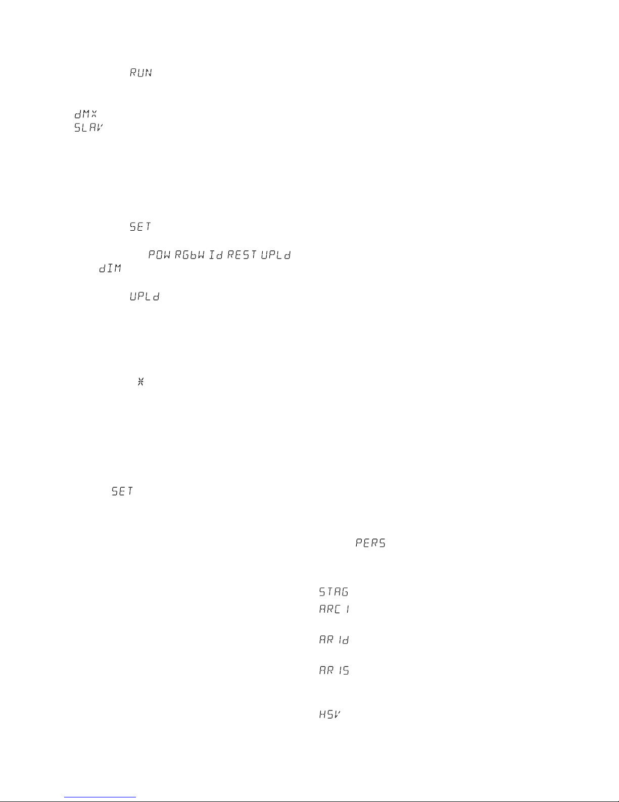
5.1.1 Farbstrahler und Stroboskop
In diesem Modus strahlt der Scheinwerfer konstant
in einer einstellbaren Farbe. Zusätzlich lässt sich die
Stroboskop-Funktion einschalten.
1) Die Taste MENU so oft drücken, bis die oberste
Menüebene erreicht ist (in der Menüstruktur auf
den Seiten 62 und 63 ganz links).
2) Die Taste UP oder DOWN so oft drücken, bis das
Display anzeigt.
3) Die Taste ENTER drücken. Das Display zeigt jetzt
, , oder und eine Zahl.
= Helligkeit Rot (0 – 255)
= Helligkeit Grün (0 – 255)
= Helligkeit Blau (0 – 255)
= Blitzfrequenz (0 – 20) des Stroboskops
4)
Mit der Taste ENTER die vier Einstellfunktionen
nacheinander anwählen und mit der Taste UP
oder DOWN jeweils die Helligkeit bzw. die Blitzfrequenz einstellen.
Tipp: Beim Einstellen der Helligkeit der Farben Rot, Grün
und Blau ändert sich nicht nur deren Helligkeit, sondern
bei einer Farbmischung auch der Farbton. Darum zuerst
die Farbe, die dominieren soll, auf die gewünschte Helligkeit einstellen und danach die anderen beiden Farben
dazumischen. Soll die Farbmischung Weiß ergeben, zuerst die Helligkeit der Farbe Grün einstellen, weil diese
dem Auge am hellsten erscheint. Dann mit Rot zu Gelb
mischen und zuletzt mit Blau zu Weiß mischen.
Wichtig: Vor dem Ausschalten des Scheinwerfers
den Menüpunkt für eine Farbe oder für die Blitzfrequenz nicht mit der Taste MENU verlassen. Ande
renfalls bleibt der Scheinwerfer nach dem Wiedereinschalten dunkel.
5.1.2 Verschiedene Weißtöne
Speichern von 11 Farbtönen
In diesem Modus strahlt der Scheinwerfer weißes
Licht ab. 11 verschiedene Weißtöne sind gespeichert, die jedoch geändert werden können. Für jeden
Weißton lässt sich die Helligkeit für die Farben Rot,
Grün und Blau unterschiedlich einstellen, sodass dieser Modus auch zum Speichern von 11 individuellen
Farbtönen genutzt werden kann.
1) Die Taste MENU so oft drücken, bis die oberste
Menüebene erreicht ist (in der Menüstruktur auf
den Seiten 62 und 63 ganz links).
2) Die Taste UP oder DOWN so oft drücken, bis das
Display anzeigt.
3)
Die Taste ENTER drücken. Das Display zeigt
jetzt einen der 11 Speicherplätze an ( …
) und der Scheinwerfer strahlt im zugehö-
rigen Weißton.
4) Mit der Taste UP oder DOWN den gewünschten
Weißton wählen oder den Speicherplatz, dessen
Einstellungen geändert werden sollen.
5)
Zum Ändern einer Einstellung nach dem Anwählen des Speicherplatzes die Taste ENTER
drücken. Das Display zeigt jetzt , , und eine
6
Deutsch
Zahl (0 – 255).
= Helligkeit Rot
= Helligkeit Grün
= Helligkeit Blau
6)
Mit der Taste ENTER die Farben nacheinander
anwählen und jeweils die Helligkeit mit der Taste
UP oder DOWN einstellen.
7)
Zum Aufrufen eines anderen Weißtons oder zum
Ändern der Einstellungen eines anderen Speicherplatzes die Taste MENU drücken, sodass wieder
die Speicherplatznummer angezeigt wird. Dann
die Bedienschritte 4 – 6 wiederholen.
Hinweis: Wird der Scheinwerfer in diesem Modus aus- und
wieder eingeschaltet, bleibt er dunkel. Der gewünschte
Weißton oder der individuelle Farbton muss erneut angewählt werden.
5.1.3 Musiksteuerung
Für einen musikgesteuerten Farbwechsel und für
die Funktion musikgesteuertes Stroboskop ist im
Scheinwerfer ein Mikrofon eingebaut.
1) Die Taste MENU so oft drücken, bis die oberste
Menüebene erreicht ist.
2) Die Taste UP oder DOWN so oft drücken, bis das
Display anzeigt.
3) Die Taste ENTER drücken. Das Display zeigt den
zuletzt gewählten Modus an:
= musikgesteuerter Farbwechsel
= musikgesteuertes Stroboskop
4) Mit der Taste UP oder DOWN den gewünschten
Modus wählen.
Wichtig: Soll der Scheinwerfer nach dem Aus- und
Einschalten wieder musikgesteuert arbeiten, den
Menüpunkt oder nicht mit der Taste
MENU verlassen.
5.1.4 Showprogramme und Szenenfolgen
10 Showprogramme ( … ) sind im
Scheinwerfer gespeichert. Außerdem können 10
Szenenfolgen ( … ) mit bis zu 30 Szenen selbst programmiert werden (☞ Kap. 5.1.5).
Die Showprogramme und Szenenfolgen lassen sich
wie folgt starten:
1) Die Taste MENU so oft drücken, bis die oberste
Menüebene erreicht ist.
2) Die Taste UP oder DOWN so oft drücken, bis das
Display anzeigt.
3)
Die Taste ENTER drücken. Das Display zeigt
jetzt das zuletzt aufgerufene Showprogramm
( … ) oder die zuletzt aufgerufene
Szenenfolge ( … ) an.
4)
Das Showprogramm oder die Szenenfolge mit
der Taste UP oder DOWN auswählen.
5.1.5 Szenenfolgen programmieren
Es lassen sich 10 Szenenfolgen auf einfache Weise
programmieren. Eine Szenenfolge kann aus max.
30 Szenen bestehen, die wiederholt abläuft. Für
jede Szene lässt sich die Farbe zusammen mit der
Helligkeit einstellen, die Stroboskop-Funktion mit
variabler Blitzfrequenz einschalten, die Szenendauer
und die Überblendzeit bestimmen.
1) Die Taste MENU so oft drücken, bis die oberste
Menüebene erreicht ist.
2) Die Taste UP oder DOWN so oft drücken, bis das
Display anzeigt.
3) Die Taste ENTER drücken. Das Display zeigt die
Nummer der Szenenfolge an, die zuletzt geändert
wurde ( … ).
4) Die Nummer, unter der die Szenenfolge gespeichert werden soll, mit der Taste UP oder DOWN
wählen und die Taste ENTER drücken. Das Display
zeigt die Nummer der ersten Szene an ( ).
5)
Durch weiteres Drücken der Taste ENTER werden nacheinander folgende Einstellfunktionen
aufgerufen:
= Helligkeit Rot
= Helligkeit Grün
= Helligkeit Blau
= Blitzfrequenz des Stroboskops
= Szenendauer (time) in Sekunden
= Überblendzeit (fade)
Mit der Taste UP oder DOWN jeweils den ge
-
wünschten Wert einstellen.
6)
Nachdem die erste Szene eingestellt ist, die Taste
MENU drücken. Das Display zeigt wieder die
Szenennummer an. Mit der Taste UP die zweite
Szene anwählen, die Taste ENTER drücken, die
Szene einstellen und den Vorgang für alle anschließenden Szenen wiederholen. Werden nicht
alle 30Szenennummern benötigt, bei den nicht
verwendeten Szenennummern die Szenendauer
auf Null einstellen.
5.2 Synchrone Steuerung mehrerer
Scheinwerfer (Master-Slave-Modus)
Es lassen sich mehrere PARC-56 / RGB oder PARC64 / RGB zusammenschließen. Das Hauptgerät (Master) kann dann alle Nebengeräte (Slave) synchron
steuern.
1) Die Scheinwerfer über die DMX-Anschlüsse mit-
einander zu einer Kette verbinden. Siehe dazu
Kapitel 5.3.1 „DMX-Anschluss“, jedoch ohne den
Bedienschritt 1 zu beachten.
2) Die Nebengeräte, die vom Hauptgerät gesteuert
werden sollen, müssen als Nebengerät eingestellt
werden.
7
Deutsch
a)
Die Taste MENU so oft drücken, bis die oberste
Menüebene erreicht ist.
b) Die Taste UP oder DOWN so oft drücken, bis
das Display anzeigt.
c) Die Taste ENTER drücken und mit der Taste UP
oder DOWN wählen:
= Hauptgerät
= Nebengerät
3) Wurden am Hauptgerät Szenenfolgen programmiert (Kap. 5.1.5), können diese auf die Nebengeräte kopiert werden:
a)
Am Hauptgerät die Taste MENU so oft drücken,
bis die oberste Menüebene erreicht ist.
b) Die Taste UP oder DOWN so oft drücken, bis
das Display anzeigt.
c) Die Taste ENTER drücken. Das Display springt
auf die Anzeige , , , ,
oder um.
d) Die Taste UP oder DOWN so oft drücken, bis
das Display anzeigt.
e)
Die Taste ENTER drücken, sodass das Display
vier Eingabestellen (. . . .) anzeigt. Dann fol-
gende Tasten drücken:
UP, DOWN, UP, DOWN.
Das Drücken dieser Tasten wird jeweils mit
einem Stern ( ) im Display quittiert.
f) Den Kopiervorgang mit der Taste ENTER star-
ten. Während des Kopiervorgangs leuchtet der
Scheinwerfer gelb, beim Auftreten eines Fehlers rot und nach einem erfolgreichen Kopieren
grün.
g) Zum Einschalten der gewünschten Betriebsart
die Taste MENU drücken, sodass das Display
wieder anzeigt. Mit der Taste UP oder
DOWN die Betriebsart auswählen und mit der
Taste ENTER aktivieren.
5.3 Betrieb mit einem DMX-Steuergerät
DMX ist die Abkürzung für Digital Multiplex und
bedeutet digitale Steuerung von mehreren DMXGeräten über eine gemeinsame Steuerleitung. Zur
Bedienung über ein DMX-Lichtsteuergerät (z. B.
DMX-1440 oder DMX-510USB von IMG STAGELINE)
verfügt der Scheinwerfer über 10 DMX-Steuerkanäle.
Er lässt sich je nach Bedarf aber auch über nur 5, 4
oder 3 Kanäle steuern. Die Funktionen der Kanäle
und die DMX-Werte sind im Kapitel 5.3.5 angegeben.
5.3.1 DMX-Anschluss
Für die DMX-Verbindung sind 3-polige XLR-Anschlüsse mit folgender Kontaktbelegung vorhanden:
Pin 1 = Masse, 2 = DMX−, 3 = DMX+
Zum Anschluss sollten spezielle Kabel für die DMX-
Signalübertragung verwendet werden (z. B. Kabel
der CDMXN-Serie). Bei Leitungslängen ab 150 m
wird grundsätzlich das Zwischenschalten eines DMXAufholverstärkers empfohlen (z. B. SR-103DMX).
1) Den Eingang DMX INPUT (1) mit dem DMX-Ausgang des Lichtsteuergerätes oder eines anderen
DMX-gesteuerten Gerätes verbinden.
2) Den Ausgang DMX OUTPUT (3) mit dem DMXEingang des nächsten DMX-Gerätes verbinden.
Dessen Ausgang wieder mit dem Eingang des
nachfolgenden DMX-Gerätes verbinden usw.,
bis alle DMX-gesteuerten Geräte in einer Kette
angeschlossen sind.
3)
Um Störungen bei der Signalübertragung auszuschließen, sollte bei langen Leitungen bzw.
bei einer Vielzahl von hintereinandergeschalteten Geräten der DMX-Ausgang des letzten
DMX-Gerätes der Kette mit einem 120-Ω-Widerstand (>0,3 W) abgeschlossen werden: In die
DMX-Ausgangsbuchse einen entsprechenden
Abschlussstecker (z. B. DLT-123) stecken.
5.3.2 Anzahl der DMX-Kanäle einstellen
Um den Scheinwerfer mit einem Lichtsteuergerät
bedienen zu können, müssen die DMX-Startadresse
(☞ Kap. 5.3.3) und die Anzahl der DMX-Kanäle eingestellt werden. Die Anzahl der DMX-Kanäle hängt
von den benötigten Funktionen ab und eventuell
auch von der Anzahl der verfügbaren Steuerkanäle
am Lichtsteuergerät. Informieren Sie sich im Kapitel
5.3.5 über die Funktionen, die jeweils im 3-, 4-, 5-
und 10-Kanal-Betrieb möglich sind und wählen Sie
danach die Anzahl der DMX-Kanäle aus:
1) Die Taste MENU so oft drücken, bis die oberste
Menüebene erreicht ist (in der Menüstruktur auf
den Seiten 62 und 63 ganz links).
2) Die Taste UP oder DOWN so oft drücken, bis das
Display anzeigt.
3) Die Taste ENTER drücken. Das Display zeigt die
momentane Einstellung an:
10 Kanäle (☞ Abb. 8, Seite 9)
3 Kanäle
1 = Rot, 2 = Grün, 3 = Blau
4 Kanäle
1 = Dimmer, 2 = Rot, 3 = Grün, 4 = Blau
5 Kanäle
1 = Dimmer, 2 = Rot, 3 = Grün,
4 = Blau, 5 = Stroboskop
3 Kanäle
1 = Farbe, 2 = Farbsättigung, 3 = Helligkeit
4)
Die Einstellung mit der Taste UP oder DOWN
auswählen.
8
Deutsch
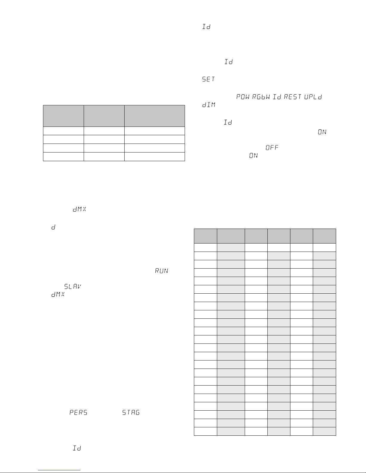
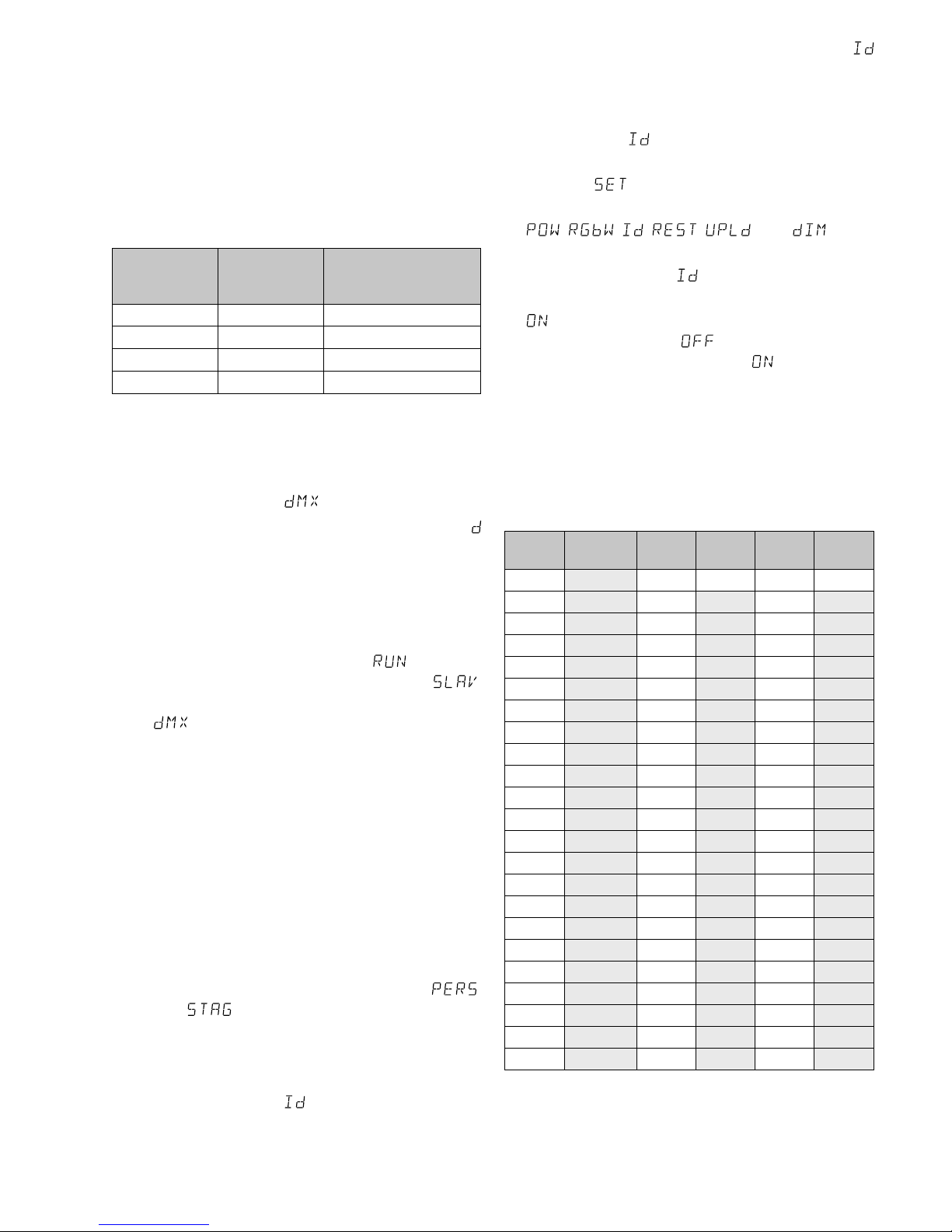
5.3.3 DMX-Startadresse einstellen
Um alle am Lichtsteuergerät angeschlossenen
DMX-Geräte separat bedienen zu können, muss
jedes Gerät eine eigene Startadresse erhalten. Soll
der erste DMX-Kanal des Scheinwerfers vom Lichtsteuergerät z. B. über die DMX-Adresse 17 gesteuert
werden, am Scheinwerfer die Startadresse 17 einstellen. Die weiteren DMX-Kanäle des des Scheinwerfers
sind dann automatisch den folgenden Adressen zugeordnet. Nachfolgend ist ein Beispiel mit der Startadresse 17 aufgeführt:
Anzahl der
DMX-Kanäle
belegte
DMX-Adressen
nächstmögliche Start-
adresse für das nachfolgende DMX-Gerät
3
17 – 19 20
4
17 – 20 21
5
17 – 21 22
10
17 – 26 27
Abb. 2 DMX-Adressenbelegung bei Verwendung der Start-
adresse 17
1) Die Taste MENU so oft drücken, bis die oberste
Menüebene erreicht ist.
2) Die Taste UP oder DOWN so oft drücken, bis das
Display anzeigt.
3) Die Taste ENTER drücken. Das Display zeigt jetzt
und eine Zahl zwischen 1 und 512.
4)
Die Startadresse mit der Taste UP oder DOWN
einstellen.
5) Der Scheinwerfer lässt sich jetzt mit einem Lichtsteuergerät bedienen.
Wenn nicht, auf den Menüpunkt springen und die Taste ENTER drücken. Zeigt das Display an, mit der Taste UP oder DOWN auf
umschalten.
5.3.4 Unteradressen verwenden
Durch die Verwendung von Unteradressen lassen
sich über eine einzige DMX-Startadresse bis zu 66
Scheinwerfer (-gruppen) unabhängig voneinander
steuern. Die maximal mögliche Anzahl DMX-gesteuerter Geräte wird dadurch erheblich erhöht.
Die Anwahl von Scheinwerfern mit einer Unteradresse erfolgt über den DMX-Kanal 10 (Abb. 8).
Alle Scheinwerfer mit einer Unteradresse lassen sich
auch synchron steuern, wenn der DMX-Kanal 10 auf
einen DMX-Wert von kleiner als 10 eingestellt wird.
1)
Den Scheinwerfer für die Steuerung über
10DMX- Kanäle einstellen, ☞ Kap. 5.3.2 (Menüpunkt , Einstellung ).
2) Die Taste MENU so oft drücken, bis die oberste
Menüebene erreicht ist.
3) Die Taste UP oder DOWN so oft drücken, bis das
Display
anzeigt.
4) Die Taste ENTER drücken. Das Display zeigt jetzt
und eine Zahl zwischen 01 und 66.
5) Die Unteradresse mit der Taste UP oder DOWN
einstellen.
6)
Die Taste MENU drücken, sodass das Display wieder nur anzeigt.
7) Die Taste UP dreimal drücken, sodass das Display
anzeigt.
8)
Die Taste ENTER drücken. Das Display springt auf
die Anzeige , , , , oder
um.
9) Die Taste UP oder DOWN so oft drücken, bis das
Display anzeigt.
10)
Die Taste ENTER drücken. Zeigt das Display an,
ist die Funktion für die Unteradressenselektion
eingeschaltet, zeigt es an, mit der Taste UP
oder DOWN auf umschalten.
11)
Damit der Scheinwerfer DMX-gesteuert werden
kann, muss durch zweimaliges Drücken der Taste
MENU zurück auf die oberste Menüebene gesprungen werden.
12)
Um den Scheinwerfer bedienen zu können, am
Lichtsteuergerät den DMX-Kanal 10 auf den
DMX-Wert stellen, welcher der Unteradresse des
Scheinwerfers entspricht:
Unter-
adresse
DMX-
Wert
Unter-
adresse
DMX-
Wert
Unter-
adresse
DMX-
Wert
alle
000 – 009
1 010 – 019 23 212 45 234
2
020 – 029 24 213 46 235
3
020 – 039 25 214 47 236
4
040 – 049 26 215 48 237
5
050 – 059 27 216 49 238
6
060 – 069 28 217 50 239
7
070 – 079 29 218 51 240
8
080 – 089 30 219 52 241
9
090 – 099 31 220 53 242
10
100 – 109 32 221 54 243
11
110 – 119 33 222 55 244
12
120 – 129 34 223 56 245
13
130 – 139 35 224 57 246
14
140 – 149 36 225 58 247
15
150 – 159 37 226 59 248
16
160 – 169 38 227 60 249
17
170 – 179 39 228 61 250
18
180 – 189 40 229 62 251
19
190 – 199 41 230 63 252
20
200 – 209 42 231 64 253
21 210 43 232 65 254
22 211 44 233 66 255
Abb. 3 Anwahl von Scheinwerfern mit einer Unteradresse
über den DMX-Kanal 10
9
Deutsch
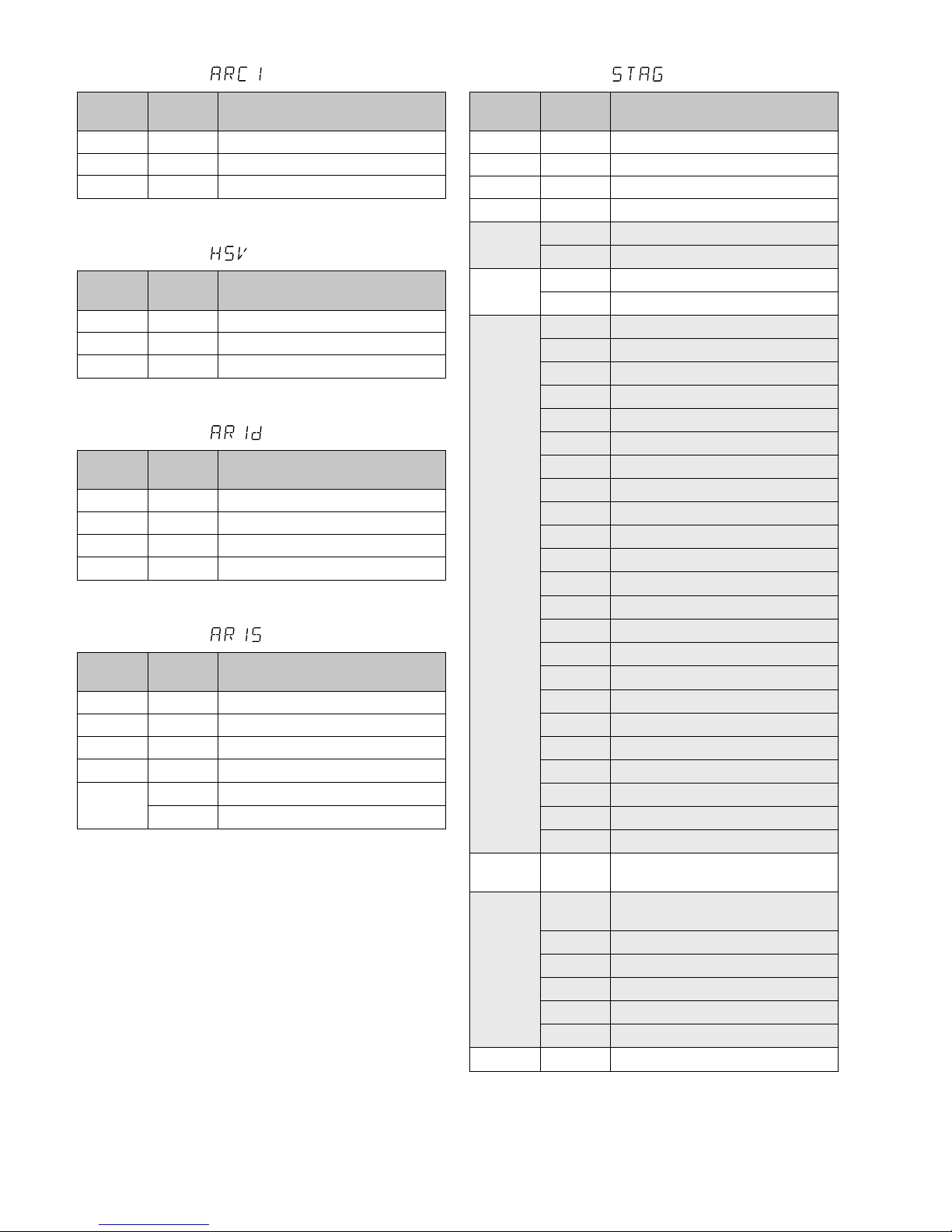
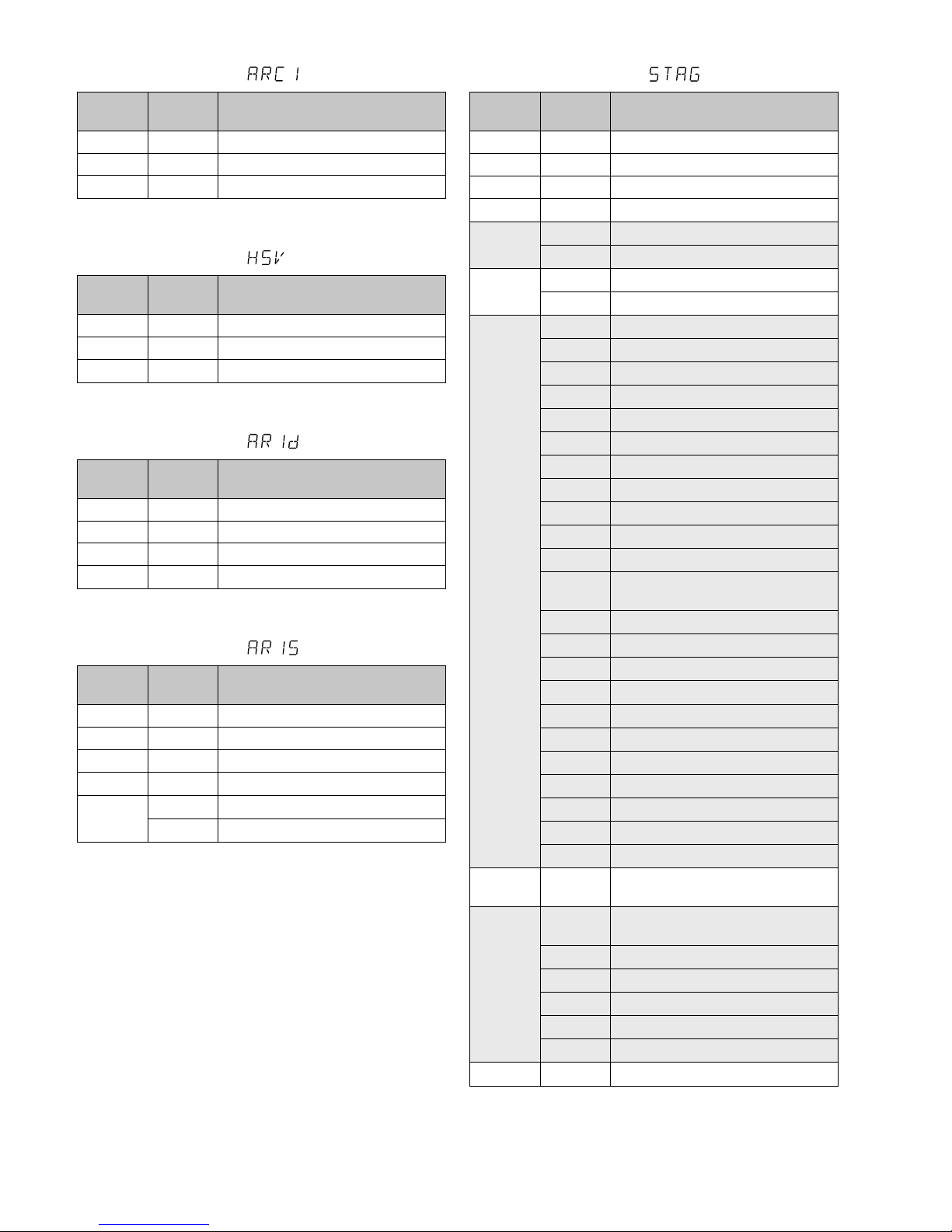
5.3.5 Funktionen der DMX-Kanäle
3-Kanal-Betrieb
DMXKanal
DMX-
Wert
Funktion
1
000 – 255 Helligkeit Rot
2
000 – 255 Helligkeit Grün
3
000 – 255 Helligkeit Blau
Abb. 4
3-Kanal-Betrieb
DMXKanal
DMX-
Wert
Funktion
1
000 – 255 Farbe
2
000 – 255 Farbsättigung
3
000 – 255 Helligkeit
Abb. 5
4-Kanal-Betrieb
DMXKanal
DMX-
Wert
Funktion
1
000 – 255
Dimmer 0 % 100 %
2 000 – 255 Grundhelligkeit Rot
3
000 – 255 Grundhelligkeit Grün
4
000 – 255 Grundhelligkeit Blau
Abb. 6
5-Kanal-Betrieb
DMXKanal
DMX-
Wert
Funktion
1
000 – 255
Dimmer 0 % 100 %
2 000 – 255 Grundhelligkeit Rot
3
000 – 255 Grundhelligkeit Grün
4
000 – 255 Grundhelligkeit Blau
5
000 – 010 kein Stroboskop
011 – 255
Stroboskop langsam schnell
Abb. 7
10-Kanal-Betrieb
DMXKanal
DMX-
Wert
Funktion
1
000 – 255
Dimmer 0 % 100 %
2 000 – 255 Grundhelligkeit Rot
3
000 – 255 Grundhelligkeit Grün
4
000 – 255 Grundhelligkeit Blau
5*
000 – 030 keine Funktion
031 – 255 verschiedene Farben
6
000 – 010 kein Stroboskop
011 – 255
Stroboskop langsam schnell
7*
000 – 020 keine Funktion
021 – 030 Showprogramm AT.01
031 – 040 Showprogramm AT.02
041 – 050 Showprogramm AT.03
051 – 060 Showprogramm AT.04
061 – 070 Showprogramm AT.05
071 – 080 Showprogramm AT.06
081 – 090 Showprogramm AT.07
091 – 100 Showprogramm AT.08
101 – 110 Showprogramm AT.09
111 – 120 Showprogramm AT.10
121 – 130
Szenenfolge PR.01, ☞ Kap. 5.1.5
131 – 140 Szenenfolge PR.02
141 – 150 Szenenfolge PR.03
151 – 160 Szenenfolge PR.04
161 – 170 Szenenfolge PR.05
171 – 180 Szenenfolge PR.06
181 – 190 Szenenfolge PR.07
191 – 200 Szenenfolge PR.08
201 – 210 Szenenfolge PR.09
211 – 220 Szenenfolge PR.10
221 – 240 musikgesteuerter Farbwechsel
241 – 255 musikgesteuertes Stroboskop
8
000 – 255
Geschwindigkeit für
die Showprogramme AT.01 – AT.10
9
000 – 009
leicht träge Reaktion der LED
☞
Kapitel 6.3
010 – 029 sofortige Reaktion der LED
030 – 069 leicht träge Reaktion 1
070 – 129 träge Reaktion 2
130 – 189 träge Reaktion 3
190 – 255 maximal träge Reaktion 4
10
000 – 255
Unteradressen, ☞ Abb. 4
Abb. 8 * Hinweis: Sollen die Funktionen des Kanals 5 oder
7 genutzt werden, den Kanal 1 auf einen DMXWert von größer als 0 einstellen, sonst bleibt der
Scheinwerfer dunkel.

10
Deutsch
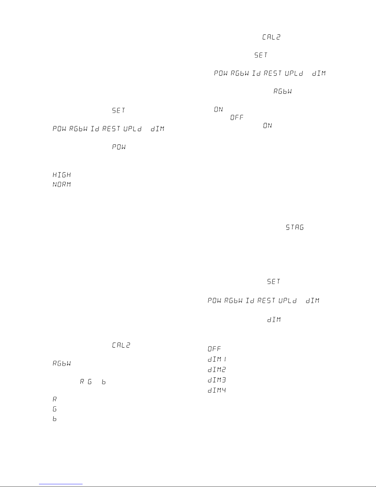
6 Zusätzliche Funktionen
6.1 Maximale Helligkeit des Scheinwerfers
Wird die maximale Helligkeit des Scheinwerfers nicht
benötigt, kann sie auf 33 % des Maximums reduziert
werden. Dadurch lässt sich die Helligkeit feinstufiger
einstellen, weil die 255 vorhandenen Helligkeitsstufen so für den reduzierten Helligkeitsbereich genutzt werden können.
1) Die Taste MENU so oft drücken, bis die oberste
Menüebene erreicht ist.
2) Die Taste UP oder DOWN so oft drücken, bis das
Display anzeigt.
3)
Die Taste ENTER drücken. Das Display springt auf
die Anzeige , , , , oder
um.
4) Die Taste UP oder DOWN so oft drücken, bis das
Display anzeigt.
5) Die Taste ENTER drücken. Das Display zeigt die
momentane Einstellung an:
= maximale Helligkeit
= auf 33 % reduzierte Helligkeit
6) Damit der Scheinwerfer DMX-gesteuert werden
kann, mit der Taste MENU zurück auf die oberste
Menüebene springen.
Für den eigenständigen Betrieb mit der Taste
MENU den Betriebsmodus wählen und mit der
Taste ENTER den Modus einschalten.
6.2 Weißabgleich
Der Scheinwerfer ist ab Werk so eingestellt, dass
bei maximaler Helligkeit der Farben Rot, Grün und
Blau ein bestimmter Weißton entsteht. Dieser Weißton kann aber auch wärmer oder kälter eingestellt
werden, z. B. um Unterschiede zu anderen Scheinwerfern auszugleichen, wenn diese gemeinsam mit dem
PARC-56 / RGB oder PARC-64 / RGB gesteuert werden.
1) Die Taste MENU so oft drücken, bis die oberste
Menüebene erreicht ist.
2) Die Taste UP oder DOWN so oft drücken, bis das
Display anzeigt.
3) Die Taste ENTER drücken. Das Display zeigt jetzt
an.
4)
Die Taste ENTER erneut drücken. Das Display
zeigt jetzt , oder und eine Zahl zwischen
000 und 255.
= Helligkeit Rot
= Helligkeit Grün
= Helligkeit Blau
5)
Mit der Taste ENTER die drei Einstellfunktionen
nacheinander anwählen und mit der Taste UP
oder DOWN jeweils die Helligkeit so einstellen,
dass sich der gewünschte Weißton ergibt.
6) Den eingestellten Weißton aktivieren:
a)
Die Taste MENU so oft drücken, bis das Display
wieder anzeigt.
b) Die Taste DOWN zweimal drücken, sodass das
Display anzeigt.
c) Die Taste ENTER drücken. Das Display springt
auf die Anzeige , , , ,
oder um.
d) Die Taste UP oder DOWN so oft drücken, bis
das Display anzeigt.
e) Die Taste ENTER drücken. Zeigt das Display
an, ist der eingestellte Weißton aktiviert; zeigt
es an, mit der Taste UP oder DOWN auf
umschalten.
7)
Damit der Scheinwerfer DMX-gesteuert werden kann, durch zweimaliges Drücken der Taste
MENU zurück auf die oberste Menüebene springen. Für den eigenständigen Betrieb mit der Taste
MENU den Betriebsmodus wählen und mit der
Taste ENTER den Modus einschalten.
6.3 Träge Reaktion der LED
LEDs reagieren auf eine Änderung der Helligkeitseinstellung sofort. Um die träge Reaktion
herkömmlicher Leuchtmittel zu simulieren, lässt
sich die Reaktion in 4 Stufen einstellen. Bei dem
10- Kanalbetrieb erfolgt diese Einstellung über
den DMX- Kanal9 (☞Abb. 8). Für den 3-, 4-, und
5-Kanal betrieb die Einstellung wie folgt vornehmen:
1) Die Taste MENU so oft drücken, bis die oberste
Menüebene erreicht ist.
2) Die Taste UP oder DOWN so oft drücken, bis das
Display anzeigt.
3)
Die Taste ENTER drücken. Das Display springt auf
die Anzeige , , , , oder
um.
4) Die Taste UP oder DOWN so oft drücken, bis das
Display
anzeigt.
5) Die Taste ENTER drücken. Das Display zeigt die
momentane Einstellung an:
= sofortige Reaktion
= leicht träge Reaktion
= träge Reaktion 2
= träge Reaktion 3
= maximal träge Reaktion
Die gewünschte Einstellung mit der Taste UP oder
DOWN wählen.
6) Damit der Scheinwerfer DMX-gesteuert werden
kann, mit der Taste MENU zurück auf die oberste
Menüebene springen.
Für den eigenständigen Betrieb mit der Taste
MENU den Betriebsmodus wählen und mit der
Taste ENTER den Modus einschalten.
11
Deutsch
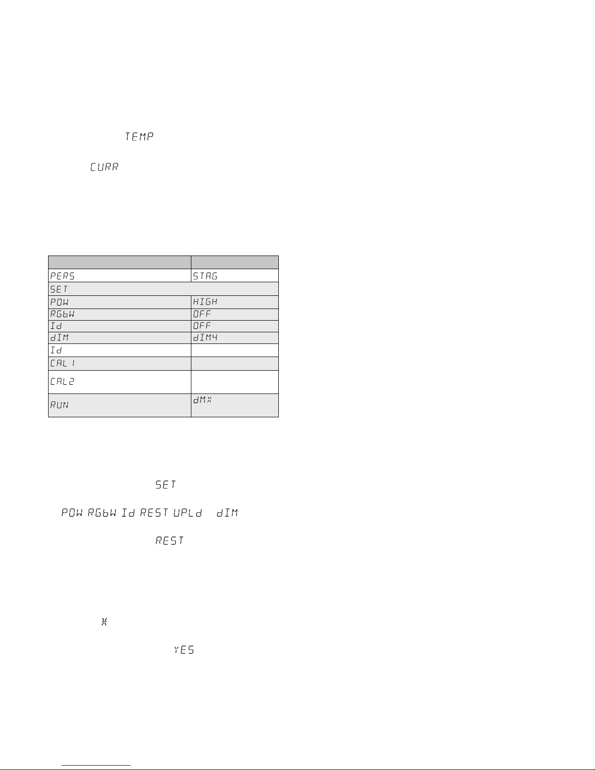
6.4 Temperaturanzeige und
Überhitzungsschutz
Der Scheinwerfer verfügt über einen Überhitzungsschutz. Dadurch schaltet er sich bei einer zu hohen
Temperatur im Inneren ab und nach dem Abkühlen
automatisch wieder ein. Zum Anzeigen der Innentemperatur:
1) Die Taste MENU so oft drücken, bis das Display
anzeigt.
2) Die Taste ENTER drücken.
3)
Wenn angezeigt wird, die Taste ENTER drücken: Die Innentemperatur wird in °C angezeigt.
4)
Mit der Taste MENU kann der Menüzweig wieder
verlassen werden.
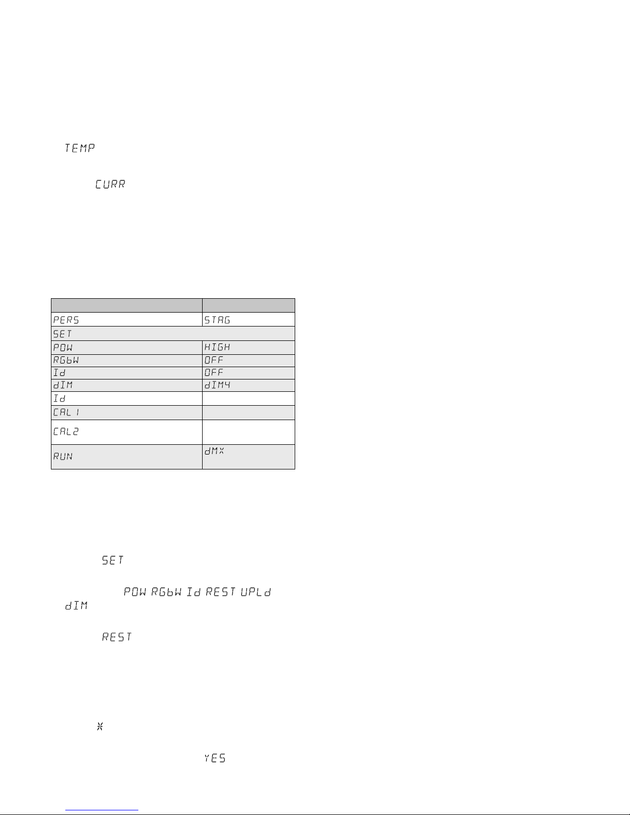
6.5 Scheinwerfer auf die Werkseinstellung
zurücksetzen
Ab Werk ist der Scheinwerfer wie folgt eingestellt:
Funktion Werkseinstellung
Anzahl der DMX-Kanäle
= 10 Kanäle
max. Helligkeit
= 100 %
Funktion Weißabgleich
= aus
Funktion Unteradresse
= aus
träge LED-Reaktion
= max. träge
Unteradresse 01
11 Weißtöne Werte ab Werk
Weißabgleich
R = 255, G = 255,
B= 255
DMX- / eigenständiger
Modus oder Slave-Modus
= DMX / eigen-
ständiger Betrieb
Zum Zurücksetzen des Scheinwerfers auf die Werkseinstellung:
1) Die Taste MENU so oft drücken, bis die oberste
Menüebene erreicht ist.
2) Die Taste UP oder DOWN so oft drücken, bis das
Display anzeigt.
3)
Die Taste ENTER drücken. Das Display springt auf
die Anzeige , , , , oder
um.
4) Die Taste UP oder DOWN so oft drücken, bis das
Display anzeigt.
5) Die Taste ENTER drücken, sodass das Display vier
Eingabestellen (. . . .) anzeigt. Dann folgende
Tasten drücken:
UP, DOWN, UP, DOWN.
Das Drücken dieser Tasten wird jeweils mit einem
Stern ( ) im Display quittiert
6) Zum Zurücksetzen die Taste ENTER drücken (das
Display quittiert dies kurz mit ) oder den Vorgang mit der Taste MENU abbrechen.
7) Damit der Scheinwerfer DMX-gesteuert werden
kann, mit der Taste MENU zurück auf die oberste
Menüebene springen.
Für den eigenständigen Betrieb mit der Taste
MENU den Betriebsmodus wählen und mit der
Taste ENTER den Modus einschalten.
7 Reinigung des Gerätes
Die Kunststoffscheibe vor der LED sollte je nach
Verschmutzung in regelmäßigen Abständen gereinigt werden. Nur dann kann das Licht in maximaler
Helligkeit abgestrahlt werden. Zum Säubern den
Netzstecker aus der Steckdose ziehen. Nur ein
weiches, sauberes Tuch und ein mildes Reinigungsmittel verwenden. Anschließend die Kunststoffscheibe trocken wischen.
Zum Reinigen der anderen Gehäuseteile nur
ein weiches, sauberes Tuch benutzen. Auf keinen
Fall eine Flüssigkeit verwenden, die könnte in das
Gerät laufen und es beschädigen.
8 Technische Daten
Datenprotokoll: . . . . . . . . . DMX 512
Anzahl der DMX-Kanäle:
. . wählbar zwischen
3, 4, 5 oder 10
Lichtquelle:
. . . . . . . . . . . . RGB-COB-LED
Leistungsaufnahme
PARC-56 / RGB: . . . . . . 50 W
PARC-64 / RGB: . . . . . . 100 W
Abstrahlwinkel: . . . . . . . 60°
Stromversorgung:
. . . . . . . 230 V/ 50 Hz
Leistungsaufnahme
PARC-56 / RGB:. . . . . . . . max. 60 VA
PARC-64 / RGB:. . . . . . . . max. 110 VA
Abmessungen
PARC-56 / RGB:. . . . . . . . ⌀ 185 mm × 210 mm
PARC-64 / RGB:. . . . . . . . ⌀ 220 mm × 260 mm
Gewicht
PARC-56 / RGB:. . . . . . . . 2,4 kg
PARC-64 / RGB:. . . . . . . . 2,9 kg
Änderungen vorbehalten.
Diese Bedienungsanleitung ist urheberrechtlich für
MONACOR ® INTERNATIONAL GmbH & Co. KG geschützt.
Eine Reproduktion für eigene kommerzielle Zwecke – auch
auszugsweise – ist untersagt.
12
English
DMX LED Spotlight
These instructions are intended for installers of the
unit and for users with basic knowledge in DMX
control. Please read the instructions carefully prior to
operation and keep them for later reference.
All operating elements and connections de-
scribed can be found on the page 2.
1 Overview
1 XLR chassis plug DMX INPUT: DMX signal input
for connecting a light controller or the DMX signal
output of another spotlight
2 Clip to secure the barn doors
3
XLR jack DMX OUTPUT: DMX signal output for
connecting the DMX input of another DMX-controlled unit
4
Mains cable for connection to a socket (230 V/ 50 Hz)
5 Locking screws for the mounting brackets
6 Mounting brackets / stand
7
Buttons to select the operating mode and to
change settings via the menu
8 Display
2 Safety Notes
The spotlight corresponds to all relevant directives of
the EU and is therefore marked with .
WARNING
The spotlight uses dangerous mains
voltage. Leave servicing to skilled personnel and do not insert anything into
the air vents; inexpert handling may
result in electric shock.
•
The spotlight is suitable for indoor use only. Protect
it against dripping water, splash water and high
air humidity. The admissible temperature range
is 0 – 40 °C.
•
Do not operate the spotlight or immediately disconnect the mains plug from the socket
1.
if the spotlight or the mains cable is visibly
damaged,
2.
if a defect might have occurred after a unit was
dropped or suffered a similar accident,
3. if malfunctions occur.
In any case the spotlight must be repaired by skilled
personnel.
•
A damaged mains cable must be replaced by
skilled personnel only.
•
Never pull the mains cable to disconnect the mains
plug from the socket, always seize the plug.
•
No guarantee claims for the spotlight and no liability for any resulting personal damage or material
damage will be accepted if the spotlight is used
for other purposes than originally intended, if it is
not safely installed or not correctly connected or
operated, or if it is not repaired in an expert way.
•
Important for U. K. Customers!
The wires in this mains lead are coloured in
ac cord ance with the following code:
green / yellow = earth
blue = neutral
brown = live
As the colours of the wires in the mains lead of this
appliance may not correspond with the coloured
markings identifying the terminals in your plug,
proceed as follows:
1. The wire which is coloured green and yellow
must be connected to the terminal in the plug
which is marked with the letter E or by the
earth symbol , or coloured green or green
and yellow.
2. The wire which is coloured blue must be connected to the terminal which is marked with
the letter N or coloured black.
3.
The wire which is coloured brown must be connected to the terminal which is marked with the
letter L or coloured red.
Warning – This appliance must be earthed.
If the spotlight is to be put out of operation
definitively, take it to a local recycling plant
for a disposal which is not harmful to the
environment.
3 Applications
This LED spotlight is used for illumination, e. g. on
stage, in discotheques and function rooms. The
light source is a high-power RGB COB LED (COB =
chip-on-board technology): Many individual LEDs in
the colours red, green and blue are mounted close
together on a chip, thus providing a uniform light
distribution. The spotlight is designed for control via
a DMX light controller (3, 4, 5 or 10 DMX control
channels), but it can also be operated independently
without a controller.
As a special feature, the spotlight supports 66
subaddresses for DMX operation. Thus, it is pos
sible to independently control up to 66 spotlights
(spotlight groups) via a single DMX start address
and the maximum number of DMX units that can
be controlled is substantially increased.
4 Setting the Spotlight into
Operation
4.1 Installation
•
Always position the spotlight in such a way that
sufficient air circulation is ensured during operation. Never cover the air vents of the housing.
13
English
•
Always keep a minimum distance of 50 cm to the
illuminated object.
WARNING
Install the spotlight safely and expertly. When installing it at a place
where people may walk or sit under it,
additionally secure it (e. g. via a safety
rope on the mounting bracket; fasten the safety
rope in such a way that the maximum falling distance of the unit will not exceed 20 cm).
1. Install the spotlight via its mounting brackets (6),
e. g. with a stable mounting screw or a support
for lighting units (C hook) to a crossbar.
To align the spotlight, release the two locking
screws (5) of the mounting brackets. Adjust the
desired inclination of the spotlight and fasten
the screws.
2.
Alternatively, set up the spotlight on its own:
Fold out the mounting brackets underneath the
spotlight and use them as a stand. Then fasten
the locking screws.
4.2 Barn doors
To reduce the light beam angle, barn doors (accessory) are available:
Barn doors Suitable for
PARC-56B
PARC-56 / RGB
PARC-64B PARC-64 / RGB
Insert the barn doors into the outer slot at the front of
the spotlight and secure them with the clip (2). To additionally secure the door barns, screw the 4screws
supplied into the threaded holes of the door barns.
4.3 Switching on
WARNING
To prevent damage to your eyes, never
look directly into the light source.
Please note that fast changes in lighting may trigger epileptic seizures with
photosensitive persons or persons
with epilepsy!
Connect the plug of the mains cable (4) to a mains
socket (230 V/ 50 Hz). Thus, the spotlight is switched
on, its display (8) will indicate the menu item most
recently selected and go out after 30 seconds. As
soon as you press one of the control buttons (7), the
display will light up again for 30 seconds.
5 Operation
To select the operating mode and the different functions, use the control buttons MENU, ENTER, UP and
DOWN (7). The menu structure on pages 62 and
63 shows how the modes and functions are selected.
5.1 Independent operation
5.1.1 Colour spotlight and stroboscope
In this mode, the spotlight constantly radiates light
of an adjustable colour. In addition, the stroboscope
function is available.
1)
Press the button MENU repeatedly until the highest menu level has been reached (on the very left
in the menu structure on pages 62 and 63).
2)
Press the button UP or DOWN repeatedly until
the display indicates .
3)
Press the button ENTER. The display now indicates
, , o and a number.
= brightness of the colour red (0 – 255)
= brightness of the colour green (0 – 255)
= brightness of the colour blue (0 – 255)
= flash rate (0 – 20) of the stroboscope
4) Use the button ENTER to select the four setting
options one after the other, and use the button
UP or DOWN to set the brightness or flash rate.
Note: Setting the brightness of the colours red, green
and blue will not only change their brightness but also
the shade of colour in case the colours are mixed. Therefore, first set the colour which is to dominate to the
desired brightness and then add the other two colours.
If the intended colour mixture is white, first set the
brightness of the green colour because it appears as
the brightest colour to the human eye. Then add red to
result in yellow and finally add blue to result in white.
Important: Do not exit the menu item for a colour
or the flash rate with the button MENU before switching off the spotlight. If you do, the spotlight will
remain dark when you switch it on again.
5.1.2 Different shades of white
Storing 11 shades of colour
In this mode, the spotlight radiates white light.
11different shades of white are stored which, however, can be changed. For each shade of white, the
colours red, green and blue can be set to a different
brightness so that this mode can also be used to
store 11 individual shades of colour.
1)
Press the button MENU repeatedly until the highest menu level has been reached (on the very left
in the menu structure on pages 62 and 63).
2)
Press the button UP or DOWN repeatedly until
the display indicates .
3)
Press the button ENTER. The display now indicates
one of the storage locations ( … ) and
the spotlight radiates the corresponding shade
of white.
4)
Press the button UP or DOWN to select the shade
of white desired or the storage locations whose
settings are to be changed.
14
English
5) To change a setting, press ENTER after you have
selected a storage location. The display now
indicates , , and a number (0 – 255).
= brightness of the colour red
= brightness of the colour green
= brightness of the colour blue
6) Use the button ENTER to select the colours one
after the other, and use the button UP or DOWN
to set their brightness.
7)
To select another shade of white or to change
the settings of another storage location, press the
button MENU so that the number of the storage
location is shown again. Then repeat steps 4 – 6.
Note: If the spotlight is switched off and on again in this
mode, the spotlight will remain dark and the shade of white
desired or the individual shade of colour will have to be
selected again.
5.1.3 Music control
The spotlight is equipped with a microphone to
support music-controlled colour changes and a
music-controlled stroboscope.
1)
Press the button MENU repeatedly until the highest menu level has been reached.
2)
Press the button UP or DOWN repeatedly until
the display indicates .
3)
Press the button ENTER. The display indicates the
mode most recently selected:
= music-controlled colour change
= music-controlled stroboscope
4) Use the button UP or DOWN to select the mode
desired.
Important: Do not exit the menu item or
via the button MENU if the spotlight is to
operate in a music-controlled mode after switch-off
and switch-on.
5.1.4 Show programmes and sequences of scenes
10 show programmes ( … ) are stored in
the spotlight. Furthermore, 10 se quences of scenes
( … ) with up to 30 scenes can be programmed (☞ chapter 5.1.5). The show programmes
and sequences of scenes can be started as follows:
1)
Press the button MENU repeatedly until the highest menu level has been reached.
2)
Press the button UP or DOWN repeatedly until
the display indicates .
3)
Press the button ENTER. The display now indicates the show programme most recently selected
( … ) or the sequence of scenes most
recently selected ( … ).
4) Use the button UP or DOWN to select the show
programme or sequence of scenes desired.
5.1.5 Programming sequences of scenes
10 sequences of scenes can be easily programmed.
A sequence may consist of up to 30 scenes which is
automatically repeated. For each scene, the colour
can be set along with its brightness, the stroboscope
function can be activated with a variable flash frequency, and the duration of the scene as well as the
fading time can be defined.
1)
Press the button MENU repeatedly until the highest menu level has been reached.
2)
Press the button UP or DOWN repeatedly until
the display indicates .
3)
Press the button ENTER. The display now indicates the number of the sequence most recently
changed ( … ).
4) Use the button UP or DOWN to select the number under which the sequence of scenes is to be
stored, and then press the button ENTER. The
display indicates the number of the first scene
( ).
5) Press the button ENTER to call up the following
setting functions:
= brightness of the colour red
= brightness of the colour green
= brightness of the colour blue
= flash frequency of the stroboscope
= duration of the scene in seconds
= fading time
Use the button UP or DOWN to set the value
desired.
6)
After setting the first scene, press the button
MENU. The display indicates the number of the
scene again. Use the button UP to select the
second scene, press ENTER and then select the
settings for this scene. Repeat this procedure for
the following scenes. If not all 30 scenes are required, enter 0 as the value for the numbers of
scenes that are not to be used.
5.2 Synchronous control of multiple
spotlights (master / slave mode)
Multiple PARC-56 / RGB or PARC-64 / RGB may be connected. The master unit can then control all slave
units in sync.
1) Connect the spotlights via their DMX jacks to a
chain. Please refer to chapter 5.3.1 “DMX connection”, ignoring step 1.
2) The units that are to be controlled by the master
unit must be defined as slave units:
a)
Press the button MENU repeatedly until the
highest menu level has been reached.
15
English
b) Press the button UP or DOWN repeatedly until
the display indicates .
c) Press the button ENTER and then use the but-
ton UP or DOWN to select:
= master unit
= slave unit
3) Any sequences of scenes that have been stored
on the master unit (chapter 5.1.5) may be copied
to the slave units:
a)
On the master unit, press the button MENU
repeatedly until the highest menu level has
been reached.
b) Press the button UP or DOWN repeatedly until
the display indicates .
c) Press the button ENTER. The display indicates
, , , , or .
d) Press the button UP or DOWN repeatedly until
the display indicates .
e)
Press the button ENTER so that the display
indicates four entry positions (. . . .). Then press
the following buttons:
UP, DOWN, UP, DOWN.
Each time one of these buttons is pressed, an
asterisk ( ) will appear on the display.
f) Press ENTER to start copying. During copying,
the spotlight lights up in yellow. If an error
occurs, the spotlight will light up in red. Upon
successful completion, the spotlight will light
up in green.
g)
To switch on the operation mode desired, press
the button MENU so that the display indicates
again. Use the buttons UP and DOWN
to select the operating mode and then press
ENTER to activate it.
5.3 Operation with a DMX controller
DMX is short for Digital Multiplex and means digital
control of multiple DMX units via a common control
line. For operation via a DMX controller (e. g. DMX1440 or DMX-510USB from IMG STAGELINE), the
spotlight is equipped with 10 DMX control channels. However, it can, if required, also be controlled
via 5, 4 or 3 channels only. Please refer to chapter
5.3.5 for more information on channel functions
and DMX values.
5.3.1 DMX connection
For DMX connection, 3-pole XLR jacks with the following pin configuration are provided:
Pin 1 = ground, 2 = DMX−, 3 = DMX+
For connection, use special cables for DMX signal
transmission (e. g. cables of the CDMXN series). For
cable lengths exceeding 150 m, it is generally recommended to insert a DMX level matching amplifier
(e. g. SR-103DMX).
1) Connect the DMX INPUT (1) to the DMX output
of the light controller or to the DMX output of
another DMX-controlled unit.
2) Connect the DMX OUTPUT (3) to the DMX input
of the following DMX unit. Connect the output of
this DMX unit to the input of the following DMX
unit etc. until all DMX-controlled units have been
connected in a chain.
3) To prevent interference in signal transmission, in
case of long cables or a multitude of units connected in series, terminate the DMX output of the
last DMX unit in the chain with a 120 Ω resistor
(> 0.3 W): Connect a corresponding terminating
plug (e. g. DLT-123) to the DMX output jack.
5.3.2 Setting the number of DMX channels
To operate the spotlight with a light controller, the
DMX start address (☞ chapter 5.3.3) and the number of DMX channels must be set. The number of
DMX channels depends on the functions required
and maybe on the number of control channels that
are available at the light controller. Please refer to
chapter 5.3.5 for more information on the functions that are provided for 3-, 4-, 5- and 10-channel
operation, and select the number of DMX channels
accordingly:
1)
Press the button MENU repeatedly until the highest menu level has been reached (on the very left
in the menu structure on pages 62 and 63).
2)
Press the button UP or DOWN repeatedly until
the display indicates .
3)
Press the button ENTER. The display now indicates
the current setting:
10 channels (☞ fig. 8; page 17)
3 channels
1 = red, 2 = green, 3 = blue
4 channels
1 = dimmer, 2 = red, 3 = green, 4 = blue
5 channels
1 = dimmer, 2 = red, 3 = green,
4 = blue, 5 = stroboscope
3 channels
1 = colour, 2 = saturation, 3 = brightness
4)
Use the button UP or DOWN to select the setting
desired.
16
English
5.3.3 Setting the DMX start address
For separate control of all DMX units connected to
the light controller, each unit must have its own start
address. If the first DMX channel of the spotlight
is to be controlled by the light controller via DMX
address 17, for example, set the start address on the
spotlight to 17. All other DMX channels of the spotlight will be automatically assigned to the following
addresses. The following table is an example with
the start address 17:
Number of
DMX channels
DMX addresses
assigned
Next possible start
address for the
succeeding DMX unit
3 17 – 19 20
4
17 – 20 21
5
17 – 21 22
10
17 – 26 27
Fig. 2 DMX address assignment for start address 17
1)
Press the button MENU repeatedly until the highest menu level has been reached.
2)
Press the button UP or DOWN repeatedly until
the display indicates .
3) Press the button ENTER. The display indicates
and a number between 1 and 512.
4) Use the button UP or DOWN to set the start address.
5)
Now the spotlight can be operated with the light
controller.
If not, go to the menu item and press
the button ENTER. If the display indicates ,
use the button UP or DOWN to set the indication
to .
5.3.4 Using subaddresses
With subaddresses, it is possible to independently
control up to 66 spotlights (spotlight groups) via
a single DMX start address. Thus, the maximum
number of DMX units that may be controlled is
substantially increased. The spotlights with a subaddress are selected via DMX channel 10 (fig. 8).
All spotlights with a subaddress may be controlled
in sync if DMX channel 10 is set to a DMX value
smaller than 10.
1)
Set the spotlight for the control via 10 DMX
channels, ☞ chapter 5.3.2 (menu item ,
setting ).
2)
Press the button MENU repeatedly until the highest menu level has been reached.
3)
Press the button UP or DOWN repeatedly until
the display indicates .
4) Press the button ENTER. The display indicates
and a number between 01 and 66.
5)
Use the button UP or DOWN to set the sub address.
6) Press the button MENU repeatedly until the display indicates
again.
7)
Press the button UP three times so that the display
indicates .
8)
Press the button ENTER. The display indicates
, , , , oder .
9)
Press the button UP or DOWN repeatedly until
the display indicates .
10)
Press the button ENTER. If the display indicates
, the function for subaddress selection is activated. If it indicates , use the button UP or
DOWN to set the indication to .
11)
To be able to control the spotlight by DMX, press
the button MENU twice to return to the highest
menu level.
12)
To be able to operate the spotlight, set the DMX
channel 10 at the light controller to the DMX
value that corresponds to the sub address of the
spotlight:
Sub-
address
DMX
value
Sub-
address
DMX
value
Sub-
address
DMX
value
all
000 – 009
1 010 – 019 23 212 45 234
2
020 – 029 24 213 46 235
3
020 – 039 25 214 47 236
4
040 – 049 26 215 48 237
5
050 – 059 27 216 49 238
6
060 – 069 28 217 50 239
7
070 – 079 29 218 51 240
8
080 – 089 30 219 52 241
9
090 – 099 31 220 53 242
10
100 – 109 32 221 54 243
11
110 – 119 33 222 55 244
12
120 – 129 34 223 56 245
13
130 – 139 35 224 57 246
14
140 – 149 36 225 58 247
15
150 – 159 37 226 59 248
16
160 – 169 38 227 60 249
17
170 – 179 39 228 61 250
18
180 – 189 40 229 62 251
19
190 – 199 41 230 63 252
20
200 – 209 42 231 64 253
21 210 43 232 65 254
22 211 44 233 66 255
Fig. 3 Selection of spotlights with a subaddress via DMX
channel 10
17
English
5.3.5 Functions of the DMX channels
3-channel operation
DMX
channel
DMX
value
Function
1
000 – 255 brightness red
2
000 – 255 brightness green
3
000 – 255 brightness blue
Fig. 4
3-channel operation
DMX
channel
DMX
value
Function
1
000 – 255 colour
2
000 – 255 saturation
3
000 – 255 brightness
Fig. 5
4-channel operation
DMX
channel
DMX
value
Function
1
000 – 255
dimmer 0 % 100 %
2 000 – 255 basic brightness red
3
000 – 255 basic brightness green
4
000 – 255 basic brightness blue
Fig. 6
5-channel operation
DMX
channel
DMX
value
Function
1
000 – 255
dimmer 0 % 100 %
2 000 – 255 basic brightness red
3
000 – 255 basic brightness green
4
000 – 255 basic brightness blue
5
000 – 010 no stroboscope
011 – 255
stroboscope slow fast
Fig. 7
10-channel operation
DMX
channel
DMX
value
Function
1
000 – 255
dimmer 0 % 100 %
2 000 – 255 basic brightness red
3
000 – 255 basic brightness green
4
000 – 255 basic brightness blue
5*
000 – 030 no function
031 – 255 different colours
6
000 – 010 no stroboscope
011 – 255
stroboscope slow fast
7*
000 – 020 no function
021 – 030 show programme AT.01
031 – 040 show programme AT.02
041 – 050 show programme AT.03
051 – 060 show programme AT.04
061 – 070 show programme AT.05
071 – 080 show programme AT.06
081 – 090 show programme AT.07
091 – 100 show programme AT.08
101 – 110 show programme AT.09
111 – 120 show programme AT.10
121 – 130
sequence of scenes PR.01,
☞
chapter 5.1.5
131 – 140 sequence of scenes PR.02
141 – 150 sequence of scenes PR.03
151 – 160 sequence of scenes PR.04
161 – 170 sequence of scenes PR.05
171 – 180 sequence of scenes PR.06
181 – 190 sequence of scenes PR.07
191 – 200 sequence of scenes PR.08
201 – 210 sequence of scenes PR.09
211 – 220 sequence of scenes PR.10
221 – 240 music-controlled colour change
241 – 255 music-controlled stroboscope
8
000 – 255
speed for
show programmes AT.01 – AT.10
9
000 – 009
slightly slow response of the LED,
☞
chapter 6.3
010 – 029 immediate response of the LED
030 – 069 slightly slow response 1
070 – 129 slow response 2
130 – 189 slow response 3
190 – 255 slowest response 4
10
000 – 255
subaddresses, ☞ fig. 4
Fig. 8 * Note: If the functions of channel 5 or 7 are to be
used, set channel 1 to a DMX value greater than 0;
otherwise, the spotlight will remain dark.
18
English
6 Additional Functions
6.1 Maximum brightness of the spotlight
If the maximum brightness of the spotlight is not
required, the brightness may be reduced to 33 % of
its maximum value. Thus, the brightness can be set
more precisely, because the 255 brightness levels are
available for a smaller brightness range.
1)
Press the button MENU repeatedly until the highest menu level has been reached.
2)
Press the button UP or DOWN repeatedly until
the display indicates .
3)
Press the button ENTER. The display indicates
, , , , or .
4)
Press the button UP or DOWN repeatedly until
the display indicates .
5)
Press the button ENTER. The display indicates the
current setting:
= maximum brightness
= brightness reduced to 33 %
6) To be able to control the spotlight by DMX, use
the button MENU to return to the highest menu
level.
For an independent operation, use the button
MENU to select the operating mode and then
press ENTER to activate the mode selected.
6.2 White balance
The factory setting of the spotlight is such that the
colours red, green and blue – when set to maximum
brightness – result in a specific shade of white. This
shade of white may be changed to appear warmer
or colder, e. g. to level out the differences to other
spotlights when they are controlled together with
the PARC-56 / RGB or PARC-64 / RGB.
1)
Press the button MENU repeatedly until the highest menu level has been reached.
2)
Press the button UP or DOWN repeatedly until
the display indicates
3)
Press the button ENTER. The display indicates
.
4) Press the button ENTER again. The display now
indicates , or and a number between 000
and 255.
= brightness of colour red
= brightness of colour green
= brightness of colour blue
5) Use the button ENTER to select the three setting
options one after the other; use the button UP
or DOWN to set the brightness for the individual
colours and thus to create the shade of white
desired.
6) To activate the shade of white that has been set:
a)
Press the button MENU repeatedly until the
display indicates again.
b) Press the button DOWN twice so that the dis-
play indicates
.
c)
Press the button ENTER. The display changes to
, , , , or .
d) Press the button UP or DOWN repeatedly until
the display indicates .
e)
Press the button ENTER. If the display indicates
, the shade of white is activated; if it indi-
cates
, use the button UP or DOWN to set
the indication to .
7) To be able to control the spotlight by DMX, press
the button MENU twice to return to the highest
menu level. For an independent operation, use
the button MENU to select the operating mode
and then press ENTER to activate the mode
selected.
6.3 Slow response of the LEDs
LEDs immediately respond to a change of the brightness setting. To simulate the slow response of stand
ard lamps, the response can be set in four steps.
For the 10-channel operation , the setting is
made via DMX channel 9 (☞ fig. 8). For 3-, 4- and
5-channel operation, make the setting as follows:
1)
Press the button MENU repeatedly until the highest menu level has been reached.
2)
Press the button UP or DOWN repeatedly until
the display indicates .
3) Press the button ENTER. The display changes to
, , , , or .
4)
Press the button UP or DOWN repeatedly until
the display indicates .
5)
Press the button ENTER. The display indicates the
current setting:
= immediate response
= slightly slow response
= slow response 2
= slow response 3
= slowest response
Use the button UP or DOWN to select the setting
desired.
6) To be able to control the spotlight by DMX, use
the button MENU to return to the highest menu
level.
For an independent operation, use the button
MENU to select the operating mode and then
press ENTER to activate the mode selected.
19
English
6.4 Temperature indication and
overheatcontrol
The spotlight is equipped with an overheat control.
When the temperature inside the spotlight is too
high, the spotlight will be switched off. After cooling down, the spotlight will be switched on again
automatically. To indicate the inside temperature:
1) Press the button MENU repeatedly until the dis-
play indicates .
2) Press the button ENTER.
3)
When is indicated, press the button ENTER.
The inside temperature will be indicated in °C.
4)
To exit the menu branch, press the button MENU.
6.5 Resetting the spotlight
toitsfactorysettings
The factory settings of the spotlight are as follows:
Function Factory setting
number of DMX channels
= 10 channels
max. brightness
= 100 %
white balance function
subaddress function
slow LED response
= slowest
subaddress 01
11 shades of white factory settings
white balance
R = 255, G = 255,
B= 255
DMX / independent mode or
slave mode
= DMX / inde-
pendent operation
To reset the spotlight to its factory settings:
1)
Press the button MENU repeatedly until the highest menu level has been reached.
2)
Press the button UP or DOWN repeatedly until
the display indicates .
3) Press the button ENTER. The display changes to
, , , , or .
4)
Press the button UP or DOWN repeatedly until
the display indicates .
5) Press the button ENTER so that the display indi-
cates four entry positions (. . . .). Then press the
following buttons:
UP, DOWN, UP, DOWN.
Each time one of these buttons is pressed, an
asterisk ( ) will appear on the display.
6)
To reset the settings, press the button ENTER (the
display briefly indicates ) or, to cancel the
procedure, press the button MENU.
7) To be able to control the spotlight by DMX, use
the button MENU to return to the highest menu
level. For an independent operation, use the but
ton MENU to select the operating mode and then
press ENTER to activate the mode selected.
7 Cleaning the Spotlight
Clean the plastic filter in front of the LEDs at regular
intervals or as required. This is the only way to ensure
that light will be radiated at maximum brightness.
Before cleaning, disconnect the mains plug from
the socket. Only use a dry, soft cloth and a mild
detergent. Then carefully wipe the plastic filter dry.
For cleaning the other parts of the housing, only
use a dry, clean cloth. Never use any fluid, it may
leak into the spotlight and damage it.
8 Specifications
Data protocol: . . . . . . . . . . DMX 512
Number of DMX channels:
selectable:
3, 4, 5 or 10
Light source:
. . . . . . . . . . . RGB COB LED
Power consumption
PARC-56 / RGB: . . . . . . 50 W
PARC-64 / RGB: . . . . . . 100 W
Beam angle: . . . . . . . . . 60°
Power supply:
. . . . . . . . . . 230 V/ 50 Hz
Power consumption
PARC-56 / RGB:. . . . . . . . 60 VA max.
PARC-64 / RGB:. . . . . . . . 110 VA max.
Dimensions
PARC-56 / RGB:. . . . . . . . ⌀ 185 mm × 210 mm
PARC-64 / RGB:. . . . . . . . ⌀ 220 mm × 260 mm
Weight
PARC-56 / RGB:. . . . . . . . 2.4 kg
PARC-64 / RGB:. . . . . . . . 2.9 kg
Subject to technical modification.
All rights reserved by MONACOR ® INTERNATIONAL GmbH &
Co. KG. No part of this instruction manual may be reproduced
in any form or by any means for any commercial use.
20
Français
Projecteur DMX à LEDs
Cette notice s’adresse à l’installateur de l‘appareil et
à l‘utilisateur avec des connaissances de base dans
la gestion DMX. Veuillez lire la présente notice avec
attention avant le fonctionnement et conservez-la
pour pouvoir, si besoin, vous y reporter ultérieurement. Vous trouverez sur la page 2, l’ensemble des
éléments et branchements.
1 Eléments et branchements
1
Fiche XLR châssis DMX INPUT: entrée signal DMX
pour brancher un contrôleur ou la sortie signal
DMX d’un autre projecteur
2 Clip pour assurer un volet
3
Fiche XLR femelle DMX OUTPUT: sortie signal
DMX pour brancher à l’entrée DMX d’un autre
appareil géré par DMX
4 Cordon secteur à relier à une prise secteur
230 V/ 50 Hz
5 Vis de fixation pour les étriers de montage
6 Etriers de montage / positionnement
7
Touches pour sélectionner le mode de fonctionnement et modifier les réglages via le menu
8 Affichage
2 Conseils d’utilisation et
desécurité
L’appareil répond à toutes les directives nécessaires
de l’Union européenne et porte donc le symbole .
AVERTISSEMENT
Le projecteur est alimenté par une
tension dangereuse. Ne touchez
jamais l’intérieur de l’appareil et
ne faites rien tomber dans les
ouïes de ventilation ! Risque de
décharge électrique.
•
L’appareil n’est conçu que pour une utilisation en
intérieur.Protégez-le de tout type de projections
d’eau, des éclaboussures, d’une humidité élevée
de l’air et de la chaleur (plage de température de
fonctionnement autorisée : 0 – 40 °C).
•
Ne faites pas fonctionner l’appareil ou débranchez-le immédiatement du secteur lorsque :
1. des dommages visibles apparaissent sur le projecteur ou sur le cordon secteur,
2. après une chute ou un cas similaire, vous avez
un doute sur l’état de l’appareil,
3. des dysfonctionnements apparaissent.
Dans tous les cas, les dommages doivent être réparés par un technicien spécialisé.
•
Tout cordon secteur endommagé ne doit être remplacé que par un technicien habilité.
•
Ne débranchez jamais l’appareil en tirant sur le
cordon secteur ; retirez toujours le cordon secteur
en tirant la fiche.
•
Nous déclinons toute responsabilité en cas de
dommages matériels ou corporels résultants si
l’appareil est utilisé dans un but autre que celui
pour lequel il a été conçu, s’il n’est pas monté
d’une manière sûre ou correctement utilisé ou s’il
n’est pas réparé par une personne habilitée, en
outre, la garantie deviendrait caduque.
Lorsque le projecteur est définitivement
retiré du service, vous devez le déposer
dans une usine de recyclage adaptée pour
contribuer à son élimination non polluante.
CARTONS ET EMBALLAGE
PAPIER À TRIER
3 Possibilités d’utilisation
Ce projecteur à LED permet un éclairage p. ex. sur
scène, dans des discothèques ou pour des salles des
fêtes. Comme source lumineuse, il possède 1 LED
RGB puissante COB (COB = chip-on-board): Beaucoup de LEDs individuelles en rouge, vert et bleu sont
montées ensemble sur une puce. On obtient ainsi
une répartition régulière de la lumière.
Le projecteur est configuré pour une gestion via
un contrôleur DMX (3, 4, 5 ou 10 canaux de commande DMX au choix). Il peut également fonctionner
seul sans contrôleur.
Particularité du projecteur: en mode DMX, l’utilisation de 66 sous-adresses. Ainsi, via une seule
adresse de démarrage DMX, on peut gérer jusqu’à
66 projecteurs (groupes de projecteurs) indépendamment les uns des autres et le nombre maximal d’appareils gérés par DMX augmente considérablement.
4 Fonctionnement
4.1 Montage
•
Placez l’appareil toujours de telle sorte que pendant le fonctionnement, une circulation d’air suffisante soit assurée. Les ouïes de ventilation du
boîtier ne doivent en aucun cas être obturées.
•
La distance avec l’objet à éclairer devrait être de
50 cm au moins.
AVERTISSEMENT Le projecteur doit être monté de
manière professionnelle et sûre.
Si l’appareil doit être installé
au-dessus de personnes, il doit
être en plus assuré (p. ex. avec
une corde de sécurité sur l’étrier de montage. Fixez
la corde de telle sorte que la distance de chute de
l’appareil ne puisse pas être supérieure à 20 cm).
 Loading...