

ELECTRONICS FOR SPECIALISTS ELECTRONICS FOR SPECIALISTS ELECTRONICS FOR SPECIALISTS ELECTRONICS FOR SPECIALISTS
BEDIENUNGSANLEITUNG
INSTRUCTION MANUAL
MODE D’EMPLOI
ISTRUZIONI PER L’USO
GEBRUIKSAANWIJZING
MANUAL DE INSTRUCCIONES
INSTRUKCJA OBSŁUGI
SIKKERHEDSOPLYSNINGER
SÄKERHETSFÖRESKRIFTER
TURVALLISUUDESTA
PARC-56 / WS Bestell-Nr. • Order No. 38.6690
PARC-64 / WS Bestell-Nr. • Order No. 38.6770
DMX-LED-Scheinwerfer
DMX LED Spotlight
2
PUSH
DMX OUTPUTDMX INPUT
ENTERMENU DOWNUP
230 V~ / 50 Hz
FUNCTION DISPLAY
1 2 3 4 5
6 7 8 9 6
MENU UP DOWNENTER
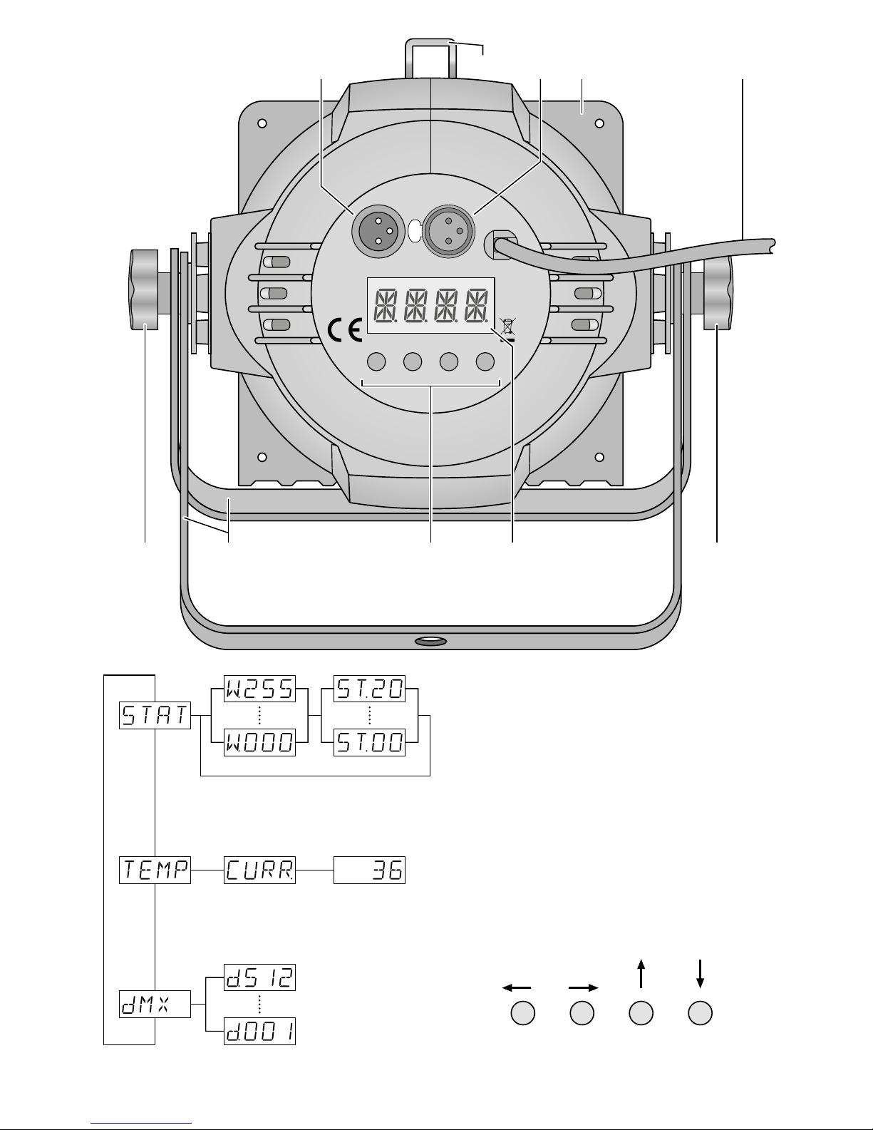
➀
Eigenständiger Betrieb: W = Helligkeit, ST= Blitzfrequenz
Independent operation: W = brightness, ST = flash rate
Fonctionnement indépendant : W = luminosité, ST = fréquence des éclairs
Funzionamento autonomo: W = luminosità, ST= frequenza lampi
DMX-Steuerung
DMX control
Gestion DMX
Comando DMX
Temperatur (°C) im Scheinwerfer
Temperature (°C) inside the spotlight
Température (°C) dans le projecteur
Temperatura (°C) nel proiettore
➁
Menüstruktur • Menu structure • Structure du menu • Struttura del menù

3
ELECTRONICS FOR SPECIALISTS ELECTRONICS FOR SPECIALISTS ELECTRONICS FOR SPECIALISTS ELECTRONICS FOR SPECIALISTS
Deutsch ..........Seite 4
English ...........Page 8
Français ..........Page 11
Italiano...........Pagina 14
Nederlands .......Pagina 17
Español ..........Página 20
Polski ............Strona 23
Dansk ............Sida 26
Svenska ..........Sidan 26
Suomi............Sivulta 27

4
Deutsch
DMX-LED-Scheinwerfer
Diese Anleitung richtet sich an den Installateur des
Geräts und an den Bediener mit Grundkenntnissen
in der DMX-Steuerung. Bitte lesen Sie die Anleitung
vor dem Betrieb gründlich durch und heben Sie sie für
ein späteres Nachlesen auf. Auf der Seite 2 finden Sie
alle beschriebenen Bedienelemente und Anschlüsse.
1 Übersicht der Anschlüsse und
Bedienelemente
1
XLR-Einbaustecker DMX INPUT: DMX-Signaleingang zum Anschluss eines Lichtsteuergerätes
oder an den DMX-Signalausgang eines anderen
Scheinwerfers
2 Klammer zum Sichern des beiliegenden Farbfilter-
rahmens (4) und einer Torblende (Zubehör)
3
XLR-Buchse DMX OUTPUT: DMX-Signalausgang
zum Anschluss an den DMX-Eingang eines weiteren DMX-gesteuerten Gerätes
4 Farbfilterrahmen
5 Netzkabel zum Anschluss an eine Steckdose
(230 V/ 50 Hz)
6 Feststellschrauben für die Montagebügel
7 Montage- /Aufstellbügel
8 Tasten zur Auswahl des Betriebsmodus und zum
Ändern von Einstellungen über das Menü
9 Display
2 Hinweise für den
sicherenGebrauch
Der Scheinwerfer entspricht allen relevanten Richtlinien der EU und trägt deshalb das -Zeichen.
WARNUNG
Das Gerät wird mit lebensgefährlicher
Netzspannung versorgt. Nehmen Sie
deshalb niemals selbst Eingriffe am
Gerät vor und stecken Sie nichts in
die Lüftungsöffnungen. Es besteht
die Gefahr eines elektrischen Schlags.
•
Verwenden Sie den Scheinwerfer nur im Innenbereich und schützen Sie ihn vor Tropf- und Spritzwasser sowie vor hoher Luftfeuchtigkeit. Der zulässige
Einsatztemperaturbereich beträgt 0 – 40 °C.
•
Nehmen Sie das Gerät nicht in Betrieb oder ziehen
Sie sofort den Netzstecker aus der Steckdose,
1.
wenn sichtbare Schäden am Gerät oder am
Netzkabel vorhanden sind,
2.
wenn nach einem Sturz oder Ähnlichem der
Verdacht auf einen Defekt besteht,
3. wenn Funktionsstörungen auftreten.
Geben Sie das Gerät in jedem Fall zur Reparatur in
eine Fachwerkstatt.
•
Ein beschädigtes Netzkabel darf nur durch eine
Fachwerkstatt ersetzt werden.
•
Ziehen Sie den Netzstecker nie am Kabel aus der
Steckdose, fassen Sie immer am Stecker an.
•
Wird das Gerät zweckentfremdet, nicht sicher
montiert, nicht richtig angeschlossen, falsch bedient oder nicht fachgerecht repariert, kann keine
Haftung für daraus resultierende Sach- oder Personenschäden und keine Garantie für das Gerät
übernommen werden.
Soll der Scheinwerfer endgültig aus dem
Betrieb genommen werden, übergeben Sie
ihn zur umweltgerechten Entsorgung einem
örtlichen Recyclingbetrieb.
3 Einsatzmöglichkeiten
Dieser LED-Scheinwerfer dient zur Beleuchtung
z. B. auf Bühnen, in Diskotheken und Festsälen. Als
Lichtquelle ist eine leistungsstarke weiße COB-LED
eingesetzt (COB = Chip-on-Board-Technologie): Viele
einzelne LEDs sind eng zusammen auf einem Chip
untergebracht. Dadurch wird eine gleichmäßige
Lichtverteilung erreicht.
Der Scheinwerfer ist für die Steuerung über ein
DMX-Lichtsteuergerät ausgelegt (3 DMX-Steuerkanäle). Er kann aber auch eigenständig ohne Steuergerät betrieben werden.
4 Inbetriebnahme
4.1 Montage
•
Platzieren Sie das Gerät immer so, dass im Betrieb
eine ausreichende Luftzirkulation gewährleistet ist.
Die Lüftungsöffnungen am Gehäuse dürfen auf
keinen Fall abgedeckt werden.
•
Der Abstand zum angestrahlten Objekt sollte mindestens 50 cm betragen.
WARNUNG
Der Scheinwerfer muss fachgerecht
und sicher montiert werden. Wird er
an einer Stelle installiert, unter der sich
Personen aufhalten können, muss er
zusätzlich gesichert werden (z. B. durch ein Fangseil am Montagebügel; das Fangseil so befestigen,
dass der Fallweg des Gerätes nicht mehr als 20 cm
betragen kann).
1. Den Scheinwerfer über die Montagebügel (7) befestigen, z. B. mit einer stabilen Montageschraube
oder einer Lichtstrahler-Halterung (C-Haken) an
einer Traverse.
Zum Ausrichten des Scheinwerfers die zwei
Feststellschrauben (6) der Montagebügel lösen.
Die gewünschte Neigung des Scheinwerfers einstellen und die Schrauben wieder festziehen.
5
Deutsch
2.
Alternativ lässt sich der Scheinwerfer auch frei aufstellen: Die Montagebügel so unter dem Scheinwerfer spreizen, dass sie als Ständer dienen. Die
Feststellschrauben danach festdrehen.
4.2 Farbfilter und Torblende
Zum Abstrahlen von farbigem Licht in den mitgelieferten Farbfilterrahmen (4) eine Farbfilterscheibe
oder eine Farbfolie (z. B. aus der Serie LCF-… von IMG
STAGELINE) einsetzen. Den Rahmen in die Schienen
vorne am Scheinwerfer schieben und mit der Klammer (2) gegen Herausfallen sichern.
Um den Lichtstrahlwinkel zu verkleinern, kann
eine Torblende eingesetzt werden:
Torblende geeignet für
PARC-56B
PARC-56 / WS
PARC-64B PARC-64 / WS
Die Blende in die äußeren Schienen vorne am Scheinwerfer hineinschieben und mit der Klammer (2)
gegen Herausfallen sichern. Zur zusätzlichen Sicherung die beiliegenden 4 Schrauben in die Gewindelöcher der Blendenhaltung schrauben.
4.3 Einschalten
WARNUNG
Blicken Sie nicht direkt in die Lichtquelle, das kann zu Augenschäden
führen.
Beachten Sie, dass sehr schnelle Lichtwechsel bei fotosensiblen Menschen
und Epileptikern epileptische Anfälle
auslösen können!
Den Stecker des Netzkabels (5) in eine Steckdose
(230 V/ 50 Hz) stecken. Der Scheinwerfer ist damit
eingeschaltet. Das Display (9) zeigt den zuletzt gewählten Menüpunkt an und erlischt nach 30 s. Sobald eine der Bedientasten (8) gedrückt wird, leuchtet
es wieder für 30 s.
5 Bedienung
Das Auswählen des Betriebsmodus und der verschiedenen Funktionen erfolgt über ein Menü mit
den Tasten MENU, ENTER, UP und DOWN (8). Die
Abbildung 2 auf der Seite 2 zeigt, wie die Modi und
Funktionen über das Menü angewählt und vom Display (9) angezeigt werden.
5.1 Eigenständiger Betrieb
Für den eigenständigen Betrieb lässt sich mit den
Bedientasten (8) die Helligkeit einstellen, die Stroboskop-Funktion einschalten und die Blitzfrequenz
einstellen.
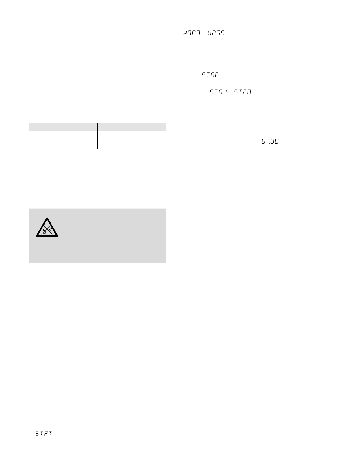
1)
Die Taste MENU so oft drücken, bis das Display
anzeigt.
2) Die Taste ENTER ein- oder zweimal drücken, sodass das Display die eingestellte Helligkeit anzeigt
( … ).
3)
Mit den Tasten UP und DOWN die gewüschte
Helligkeit einstellen.
4)
Soll die Stroboskop-Funktion eingeschaltet werden, die Taste ENTER erneut drücken, sodass das
Display anzeigt.
5) Mit den Tasten UP und DOWN die Blitzfrequenz
einstellen ( … ).
6)
Zum Ändern der Blitzhelligkeit mit der Taste ENTER
auf den Menüpunkt für die Helligkeit zurückschalten und den Wert mit der Taste UP oder DOWN
ändern.
7)
Soll die Stroboskop-Funktion wieder ausgeschaltet
werden, die Blitzfrequenz auf einstellen.
Wichtig: Vor dem Ausschalten des Scheinwerfers
den Menüpunkt für die Helligkeit oder Blitzfrequenz
nicht mit der Taste MENU verlassen. Anderenfalls
bleibt der Scheinwerfer nach dem Wiedereinschalten
dunkel.
5.2 Betrieb mit einem DMX-Steuergerät
Zur Bedienung über ein DMX-Lichtsteuergerät (z. B.
DMX-1440 oder DMX-510USB von IMG STAGELINE)
verfügt der Scheinwerfer über vier DMX-Steuerkanäle. DMX ist die Abkürzung für Digital Multiplex
und bedeutet digitale Steuerung von mehreren
DMX-Geräten über eine gemeinsame Steuerleitung.
Die Funktionen der Kanäle und die DMX-Werte sind
im Kapitel 5.2.3 angegeben.
5.2.1 DMX-Anschluss
Für die DMX-Verbindung sind 3-polige XLR-Anschlüsse mit folgender Kontaktbelegung vorhanden:
Pin 1 = Masse, 2 = DMX−, 3 = DMX+
Zum Anschluss sollten spezielle Kabel für die DMX-
Signalübertragung verwendet werden (z. B. Kabel der
CDMXN-Serie). Bei Leitungslängen ab 150 m wird
grundsätzlich das Zwischenschalten eines DMX-Aufholverstärkers empfohlen (z. B. SR-103DMX).
1) Den Eingang DMX INPUT (1) mit dem DMX-Ausgang des Lichtsteuergerätes oder eines anderen
DMX-gesteuerten Gerätes verbinden.
2)
Den Ausgang DMX OUTPUT (3) mit dem DMX-Eingang des nächsten DMX-Gerätes verbinden.
Dessen Ausgang wieder mit dem Eingang des
nachfolgenden DMX-Gerätes verbinden usw.,
bis alle DMX-gesteuerten Geräte in einer Kette
angeschlossen sind.
3) Um Störungen bei der Signalübertragung auszuschließen, sollte bei langen Leitungen bzw. bei
einer Vielzahl von hintereinandergeschalteten

6
Deutsch
Geräten der DMX-Ausgang des letzten DMX-Gerätes der Kette mit einem 120-Ω-Widerstand (>
0,3 W) abgeschlossen werden: In die DMX-Ausgangsbuchse einen entsprechenden Abschlussstecker (z. B. DLT-123) stecken.
5.2.2 DMX-Startadresse einstellen
Um alle am Lichtsteuergerät angeschlossenen
DMX-Geräte separat bedienen zu können, muss
jedes Gerät eine eigene Startadresse erhalten. Soll
der erste DMX-Kanal des Scheinwerfers vom Lichtsteuergerät z. B. über die DMX-Adresse 17 gesteuert
werden, am Scheinwerfer die Startadresse 17 einstellen. Alle weiteren DMX-Kanäle des Scheinwerfers sind dann automatisch den darauffolgenden
Adressen zugeordnet (z. B bei der Startadresse 17
die Adressen 18 und 19).
1)
Die Taste MENU so oft drücken, bis das Display
anzeigt.
2)
Die Taste ENTER drücken. Das Display zeigt die
eingestellte Startadresse an ( … ).
3)
Mit den Tasten UP und DOWN die gewünschte
Adresse einstellen. Der Scheinwerfer lässt sich jetzt
mit dem Lichtsteuergerät bedienen.
Hinweis: Zeigt das Display den Menüpunkt ,
oder , blinkt ganz rechts der Punkt, wenn DMXSignale am DMX-Eingang (1) anliegen.
5.2.3 DMX-Kanäle und -Funktionen
DMX- Kanal DMX-Wert Funktion
1
000 – 255
Helligkeit 0 % 100 %
2
Reaktion der Helligkeitssteuerung
000 leicht träge Reaktion
001 – 255
Reaktion sehr träge schnell
251 – 255 sofortige Reaktion
3
000 – 010 Stroboskop aus
011 – 255
Stroboskop langsam schnell
➂
DMX-Kanäle
5.3 Temperaturanzeige und
Überhitzungsschutz
Der Scheinwerfer verfügt über einen Überhitzungsschutz. Dadurch schaltet er sich bei einer zu hohen
Temperatur im Inneren ab und nach dem Abkühlen
automatisch wieder ein. Zum Anzeigen der Innentemperatur:
1)
Die Taste MENU so oft drücken, bis das Display
anzeigt.
2)
Die Taste ENTER drücken. Das Display zeigt
an.
3)
Die Taste ENTER erneut drücken: Die Innentemperatur wird in °C angezeigt.
4) Mit der Taste MENU kann der Menüzweig wieder
verlassen werden.
6 Reinigung des Gerätes
Die Kunststoffscheibe vor der LED sollte je nach
Verschmutzung in regelmäßigen Abständen gereinigt werden. Nur dann kann das Licht in maximaler
Helligkeit abgestrahlt werden. Zum Säubern den
Netzstecker aus der Steckdose ziehen. Nur ein
weiches, sauberes Tuch und ein mildes Reinigungsmittel verwenden. Anschließend die Kunststoffscheibe trocken wischen.
Zum Reinigen der anderen Gehäuseteile nur ein
weiches, sauberes Tuch benutzen. Auf keinen Fall
eine Flüssigkeit verwenden, die könnte in das Gerät
laufen und es beschädigen.
7 Technische Daten
Datenprotokoll: . . . . . . . . . DMX 512
Anzahl der DMX-Kanäle:
. . 3
Lichtquelle:
. . . . . . . . . . . . weiße COB-LED
Leistungsaufnahme
PARC-56 / WS: . . . . . . . . 50 W
PARC-64 / WS: . . . . . . . . 100 W
Abstrahlwinkel: . . . . . . . 60°
Farbtemperatur: . . . . . . 5600 K
Stromversorgung: . . . . . . . 230 V/ 50 Hz
Leistungsaufnahme
PARC-56 / WS: . . . . . . . . max. 60 VA
PARC-64 / WS: . . . . . . . . max. 110 VA
Abmessungen
PARC-56 / WS: . . . . . . . . ∅ 185 mm × 210 mm
PARC-64 / WS: . . . . . . . . ∅ 220 mm × 260 mm
Gewicht
PARC-56 / WS: . . . . . . . . 2,5 kg
PARC-64 / WS: . . . . . . . . 3,2 kg
Änderungen vorbehalten.
Diese Bedienungsanleitung ist urheberrechtlich für MONACOR ® INTERNATIONAL GmbH & Co. KG geschützt. Eine
Reproduktion für eigene kommerzielle Zwecke – auch auszugsweise – ist untersagt.

7
8
English
DMX LED Spotlight
These instructions are intended for installers of the
unit and for users with basic knowledge in DMX
control. Please read the instructions carefully prior to
operation and keep them for later reference.
All operating elements and connections de-
scribed can be found on page 2.
1 Operating Elements
andConnections
1
XLR chassis plug DMX INPUT: DMX signal input
for connecting a light controller or the DMX signal
output of another spotlight
2 Clip to secure the colour filter frame (4) provided
and the barn doors (optional)
3
XLR jack DMX OUTPUT: DMX signal output for
connecting the DMX input of another DMX-controlled unit
4 Colour filter frame
5 Mains cable for connection to a socket
(230 V/ 50 Hz)
6 Locking screws for the mounting brackets
7 Mounting brackets / stand
8
Buttons to select the operating mode and to
change settings via the menu
9 Display
2 Safety Notes
The spotlight corresponds to all relevant directives of
the EU and is therefore marked with .
WARNING
The spotlight uses dangerous mains
voltage. Leave servicing to skilled personnel and do not insert anything into
the air vents; inexpert handling may
result in electric shock.
•
The spotlight is suitable for indoor use only. Protect
it against dripping water, splash water and high
air humidity. The admissible temperature range
is 0 – 40 °C).
•
Do not operate the spotlight or immediately disconnect the mains plug from the socket
1.
if the spotlight or the mains cable is visibly
damaged,
2. if a defect might have occurred after a unit was
dropped or suffered a similar accident,
3. if malfunctions occur.
In any case the spotlight must be repaired by skilled
personnel.
•
A damaged mains cable must be replaced by skilled
personnel only.
•
Never pull the mains cable to disconnect the mains
plug from the socket, always seize the plug.
•
No guarantee claims for the spotlight and no liability for any resulting personal damage or material
damage will be accepted if the spotlight is used
for other purposes than originally intended, if it is
not safely installed or not correctly connected or
operated, or if it is not repaired in an expert way.
•
Important for UK Customers!
The wires in this mains lead are coloured in
ac cord ance with the following code:
green / yellow = earth
blue = neutral
brown = live
As the colours of the wires in the mains lead of this
appliance may not correspond with the coloured
markings identifying the terminals in your plug,
proceed as follows:
1.
The wire which is coloured green and yellow
must be connected to the terminal in the plug
which is marked with the letter E or by the
earth symbol , or coloured green or green
and yellow.
2. The wire which is coloured blue must be connected to the terminal which is marked with the
letter N or coloured black.
3.
The wire which is coloured brown must be connected to the terminal which is marked with the
letter L or coloured red.
Warning – This appliance must be earthed.
If the spotlight is to be put out of operation
definitively, take it to a local recycling plant
for a disposal which is not harmful to the
environment.
3 Applications
This LED spotlight is used for illumination, e. g. on
stage, in discotheques and function rooms. The
light source is a white high-power COB LED (COB =
chip-on-board technology): Many individual LEDs are
mounted close together on a chip, thus providing a
uniform light distribution.
The spotlight is designed for control via a DMX
light controller (3 DMX control channels), but it can
also be operated independently without a controller.
4 Setting the Spotlight into Operation
4.1 Installation
•
Always position the spotlight in such a way to
ensure sufficient air circulation during operation.
Never cover the air vents of the housing.

9
English
•
Always keep a minimum distance of 50 cm to the
illuminated object.
WARNING
Install the spotlight safely and expertly. When installing it at a place
where people may walk or sit under it,
additionally secure it (e. g. via a safety
rope on the mounting bracket; fasten the safety
rope in such a way that the maximum falling distance of the unit will not exceed 20 cm).
1. Install the spotlight via its mounting brackets (7),
e. g. with a stable mounting screw or a support
for lighting units (C hook) to a cross bar.
To align the spotlight, release the two locking
screws (6) of the mounting brackets. Adjust the
desired inclination of the spotlight and fasten the
screws.
2.
Alternatively, set up the spotlight on its own: Fold
out the mounting brackets underneath the spotlight and use them as a stand. Then fasten the
locking screws.
4.2 Colour filter and barn doors
For radiating coloured light, insert a colour filter or
a coloured filter foil (e. g. LCF-… series from IMG
STAGELINE) into the colour filter frame (4) provided.
Slide the frame into the slot at the front of the spotlight and secure it with the clip (2).
To reduce the light beam angle, barn doors (ac-
cessory) are available:
Barn doors Suitable for
PARC-56B
PARC-56 / WS
PARC-64B PARC-64 / WS
Insert the barn doors into the outer slot at the front of
the spotlight and secure them with the clip (2). To additionally secure the door barns, screw the 4 screws
supplied into the threaded holes of the door barns.
4.3 Switching on
WARNING
To prevent damage to your eyes, never
look directly into the light source.
Please note that fast changes in lighting may trigger epileptic seizures with
photosensitive persons or persons
with epilepsy!
Connect the plug of the mains cable (5) to a mains
socket (230 V/ 50 Hz). Thus, the spotlight is switched
on, its display (9) will indicate the menu item most
recently selected and go out after 30seconds. As
soon as you press one of the control buttons (8), the
display will light up again for 30 seconds.
5 Operation
To select the operating mode and the different functions, use the menu via the control buttons MENU,
ENTER, UP and DOWN (8). Figure 2 on page 2 shows
the selection of the modes and functions via the
menu and the indications on the display (9).
5.1 Independent operation
For independent operation, use the control buttons
(8) to set the brightness, to switch on the stroboscope
function and to set the flash rate.
1)
Press the button MENU repeatedly until
appears on the display.
2)
Press the button ENTER once or twice so that
the display will indicate the brightness adjusted
( … ).
3)
To set the desired brightness, press the buttons
UP and DOWN.
4)
To activate the stroboscope function, press the
button ENTER once again so that the display will
indicate
.
5)
To set the flash rate ( … ), press the
buttons UP and DOWN.
6) To change the brightness of the flash, press the
button ENTER to return to the menu item for the
brightness. To change the value, press the button
UP or DOWN.
7)
To deactivate the stroboscope function, set the
flash rate to .
Important: Do not exit the menu item for the brightness or the flash rate with the button MENU before
switching off the spotlight. If you do, the spotlight
will remain dark when you switch it on again.
5.2 Operation with a DMX controller
For operation via a DMX light controller (e. g. DMX1440 or DMX-510USB), the spotlight is equipped
with four DMX control channels. DMX is short for
digital multiplex and means digital control of several
DMX units via a common control cable. The functions
of the channels and the DMX values can be found
in chapter 5.2.3.
5.2.1 DMX connection
For DMX connection, 3-pole XLR connectors with the
following pin configuration are provided:
Pin 1 = ground, 2 = DMX−, 3 = DMX+
For connection, use special cables for DMX signal
transmission (e. g. cables of the CDMXN series from
IMG STAGELINE). For cable lengths exceeding 150 m,
it is generally recommended to insert a DMX level
matching amplifier (e. g. SR-103DMX).

10
English
1) Connect the DMX INPUT (1) to the DMX output
of the light controller or to the DMX output of
another DMX-controlled unit.
2) Connect the DMX OUTPUT (3) to the DMX input
of the following DMX unit. Connect the output of
this DMX unit to the input of the following DMX
unit etc. until all DMX-controlled units have been
connected in a chain.
3) To prevent interference in signal transmission, in
case of long cables or a multitude of units connected in series, terminate the DMX output of the
last DMX unit in the chain with a 120 Ω resistor
(>0.3 W): Connect a corresponding terminating
plug (e. g. DLT-123) to the DMX output jack.
5.2.2 Setting the DMX start address
For separate control of all DMX units connected to
the light controller, each unit must have its own start
address. Example: If the first DMX channel of the
spotlight is to be controlled by the controller via DMX
address 17, set the start address on the spotlight to
17. All other DMX channels of the spotlight will be
automatically assigned to the following addresses
(i. e. 18 and 19 in case of start address 17).
1)
Press the button MENU repeatedly until
appears on the display.
2)
Press the button ENTER. The start address adjusted
( … ) will be indicated.
3) To set the desired address, press the buttons UP
and DOWN. Now the spotlight can be operated
with the light controller.
Notes: When the menu item , or appears
on the display and DMX signals are available at the DMX
input (1), the dot at the right end of the display will flash.
5.2.3 DMX channels and functions
DMX
channel
DMX
value
Function
1
000 – 255
brightness 0 % 100 %
2
response of brightness control
000 slow response
001 – 255
response very slow fast
251 – 255 immediate response
3
000 – 010 stroboscope off
011 – 255
stroboscope slow fast
➂
DMX channels
5.3 Temperature indication and
overheatcontrol
The spotlight is equipped with an overheat control.
When the temperature inside the spotlight is too
high, the spotlight will be switched off. After cooling down, the spotlight will be switched on again
automatically. To indicate the inside temperature:
1)
Press the button MENU repeatedly until
appears on the display.
2) Press the button ENTER. will appear on the
display.
3) Press the button ENTER again. The inside temper-
ature (in °C) is indicated on the display.
4) To exit the menu branch, press the button MENU.
6 Cleaning the Spotlight
Clean the plastic pane in front of the LEDs at regular
intervals or as required. This is the only way to ensure
that light will be radiated at maximum brightness.
Before cleaning, disconnect the mains plug from
the socket. Only use a soft clean cloth and a mild
detergent. Then carefully wipe the plastic pane dry.
For cleaning the other parts of the housing, only
use a soft clean cloth. Never use any fluid; it may leak
into the spotlight and damage it.
7 Specifications
Data protocol: . . . . . . . . . . DMX 512
Number of DMX channels:
3
Light source:
. . . . . . . . . . . white COB LED
Power consumption
PARC-56 / WS: . . . . . . . . 50 W
PARC-64 / WS: . . . . . . . . 100 W
Beam angle: . . . . . . . . . 60°
Colour temperature: . . . 5600 K
Power supply: . . . . . . . . . . 230 V/ 50 Hz
Power consumption
PARC-56 / WS: . . . . . . . . 60 VA max.
PARC-64 / WS: . . . . . . . . 110 VA max.
Dimensions
PARC-56 / WS: . . . . . . . . ∅ 185 mm × 210 mm
PARC-64 / WS: . . . . . . . . ∅ 220 mm × 260 mm
Weight
PARC-56 / WS: . . . . . . . . 2.5 kg
PARC-64 / WS: . . . . . . . . 3.2 kg
Subject to technical modification.
All rights reserved by MONACOR ® INTERNATIONAL GmbH & Co. KG. No part of this instruction manual may be
reproduced in any form or by any means for any commercial use.

11
Français
Projecteur DMX à LEDs
Cette notice s’adresse à l’installateur de l‘appareil et
à l‘utilisateur avec des connaissances de base dans
la gestion DMX. Veuillez lire la présente notice avec
attention avant le fonctionnement et conservez-la
pour pouvoir, si besoin, vous y reporter ultérieurement. Vous trouverez sur la page 2, l’ensemble des
éléments et branchements.
1 Eléments et branchements
1 Fiche XLR châssis DMX INPUT: entrée signal DMX
pour brancher un contrôleur ou la sortie signal
DMX d’un autre projecteur
2
Clip pour sécuriser le cadre de filtre de couleur
livré(4) et des volets (disponibles en option)
3
Fiche XLR femelle DMX OUTPUT: sortie signal
DMX pour brancher à l’entrée DMX d’un autre
appareil géré par DMX
4 Cadre de filtre de couleur
5 Cordon secteur à relier à une prise secteur
230 V/ 50 Hz
6 Vis de fixation pour les étriers de montage
7 Etriers de montage / positionnement
8
Touches pour sélectionner le mode de fonctionnement et modifier les réglages via le menu
9 Affichage
2 Conseils d’utilisation
etdesécurité
L’appareil répond à toutes les directives nécessaires
de l’Union européenne et porte donc le symbole
.
AVERTISSEMENT Le projecteur est alimenté par une
tension dangereuse. Ne touchez
jamais l’intérieur de l’appareil et
ne faites rien tomber dans les ouïes
de ventilation ! Risque de décharge
électrique.
•
L’appareil n’est conçu que pour une utilisation en
intérieur. Protégez-le des éclaboussures, de tout
type de projections d‘eau et d’une humidité d‘air
élevée. La plage de température ambiante admissible est de 0 – 40 °C.
•
Ne faites pas fonctionner l’appareil ou débranchez-le immédiatement du secteur lorsque :
1. des dommages visibles apparaissent sur le projecteur ou sur le cordon secteur,
2. après une chute ou un cas similaire, vous avez
un doute sur l’état de l’appareil,
3. des dysfonctionnements apparaissent.
Dans tous les cas, les dommages doivent être
réparés par un technicien spécialisé.
•
Tout cordon secteur endommagé ne doit être remplacé que par un technicien habilité.
•
Ne débranchez jamais l’appareil en tirant sur le
cordon secteur ; retirez toujours le cordon secteur
en tirant la fiche.
•
Nous déclinons toute responsabilité en cas de dommages matériels ou corporels résultants si l’appareil
est utilisé dans un but autre que celui pour lequel
il a été conçu, s’il n’est pas monté d’une manière
sûre, correctement utilisé ou n’est pas réparé par
une personne habilitée, en outre, la garantie deviendrait caduque.
Lorsque le projecteur est définitivement
retiré du service, vous devez le déposer
dans une usine de recyclage adaptée pour
contribuer à son élimination non polluante.
CARTONS ET EMBALLAGE
PAPIER À TRIER
3 Possibilités d’utilisation
Ce projecteur à LED permet un éclairage par exemple
sur scène, dans des discothèques ou pour des salles
des fêtes. Comme source lumineuse, il possède 1LED
blanche puissante COB (COB = chip-on-board):
Beaucoup de LEDs individuelles sont montées ensemble sur une puce. On obtient ainsi une répartition
régulière de la lumière.
Le projecteur est configuré pour une gestion via
un contrôleur DMX (3 canaux de commande DMX).
Il peut également fonctionner seul sans contrôleur.
4 Fonctionnement
4.1 Montage
•
Placez l’appareil toujours de telle sorte que pendant
le fonctionnement, une circulation d’air suffisante
soit assurée. Les ouïes de ventilation du boîtier ne
doivent en aucun cas être obturées.
•
La distance avec l’objet à éclairer devrait être de
50 cm au moins.
AVERTISSEMENT
Le projecteur doit être monté de
manière professionnelle et sûre.
Si l’appareil est installé au-dessus
de personnes, il doit être en plus
assuré (par exemple avec une corde de sécurité sur
l’étrier de montage. Fixez la corde de telle sorte que
la distance de chute de l’appareil ne puisse pas être
supérieure à 20 cm).
1. Fixez le projecteur via les étriers de montage (7)
par exemple via une vis de montage solide ou un
support pour projecteur (crochet C) à une traverse.

12
Français
Pour orienter le projecteur, desserrez les deux
vis (6) sur les étriers de montage. Réglez l’inclinaison voulue puis revissez les vis.
2.
A la place, vous pouvez poser le projecteur librement. Pour ce faire, dépliez les étriers sous le
projecteur pour qu’ils servent de support. Revissez
ensuite les vis de fixation.
4.2 Filtre de couleur et volets
Pour diffuser une lumière de couleur, insérez un filtre
de couleur ou une feuille de gélatine (par exemple de
la série LCF-… de IMG STAGELINE) dans le cadre de
filtre de couleur livré (4). Faites glisser le cadre dans
les rails sur l’avant du projecteur et verrouillez-le avec
le clip (2) pour éviter qu’il ne tombe.
Pour réduire l’angle de diffusion, des volets (dis-
ponibles en option) peuvent être installés :
Volets Adapté pour
PARC-56B
PARC-56 / WS
PARC-64B PARC-64 / WS
Poussez les volets dans les rails extérieurs sur la face
avant du projecteur et sécurisez avec le clip (2) pour
éviter toute chute. Pour une sécurité supplémentaire,
vissez les 4 vis livrées dans les trous filetés du support
des volets.
4.3 Allumage
AVERTISSEMENT
Ne regardez jamais directement
la source de lumière, cela pourrait
causer des troubles de la vision.
N’oubliez pas que des changements très rapides de lumière peuvent déclencher
des crises d’épilepsie chez les personnes photosensibles et épileptiques.
Reliez la fiche du cordon secteur (5) à une prise
secteur 230 V/ 50 Hz, le projecteur est alors allumé.
L’affichage(9) indique le dernier point du menu sélectionné et s’éteint après 30 secondes. Dès qu’une
des touches de commande (8) est enfoncée, il brille
à nouveau pendant 30 secondes.
5 Utilisation
La sélection du mode de fonctionnement et des différentes fonctions s’effectue via un menu avec les
touches MENU, ENTER, UP et DOWN (8). Le schéma2,
page 2, indique comment les modes sont sélectionnés via le menu et indiqués sur l’affichage(9).
5.1 Fonctionnement indépendant
Pour le fonctionnement indépendant, vous pouvez
régler, avec les touches (8), la luminosité, activer
la fonction stroboscope et régler la fréquence des
éclairs.
1) Appuyez sur la touche MENU de manière répétée
jusqu’à ce que l’affichage indique .
2)
Appuyez sur la touche ENTER une ou deux fois
pour que l’affichage indique la luminosité réglée
( … ).
3)
Avec les touches UP et DOWN, réglez la luminosité
voulue.
4)
Si la fonction stroboscope doit être activée, appuyez à nouveau sur la touche ENTER pour que
l’affichage indique .
5)
Avec les touches UP et DOWN, réglez la fréquence
des éclairs ( … ).
6)
Pour modifier la luminosité des éclairs, revenez
avec la touche ENTER sur le point de menu pour
la luminosité et modifiez la valeur avec la touche
UP ou DOWN.
7) Pour désactiver la fonction stroboscope, réglez la
fréquence des éclairs sur .
Important: Ne quittez pas le point de menu pour la
luminosité ou la fréquence des éclairs avec la touche
MENU avant d’éteindre le projecteur. Sinon le projecteur reste sombre lorsque vous le rallumez.
5.2 Fonctionnement avec un contrôleur DMX
Pour une gestion via un contrôleur DMX (par exemple
DMX-1440 ou DMX-510USB de IMG STAGELINE), le
projecteur dispose de 4 canaux de commande DMX.
DMX est l’abréviation de Digital Multiplex et signifie
commande digitale de plusieurs appareils DMX via
un câble commun de commande. Vous trouverez
les fonctions des canaux et les valeurs DMX dans le
chapitre
5.2.3.
5.2.1 Branchement DMX
Pour la connexion DMX, des branchements XLR
3 pôles avec la configuration de contact suivante
sont prévus:
Pin 1 = masse, 2 = DMX−, 3 = DMX+
Pour le branchement, il est recommandé d’utiliser
des câbles spécifiques pour la transmission de signaux DMX (par exemple câbles des séries CDMXN).
Pour des longueurs de liaison à partir de 150 m, il est
recommandé d’insérer un amplificateur répétiteur
DMX(par exemple SR-103DMX).
1) Reliez l’entrée DMX INPUT (1) à la sortie DMX du
contrôleur ou d’un autre appareil géré par DMX.
2) Reliez la sortie DMX OUTPUT (3) à l’entrée DMX
du prochaine appareil DMX. Reliez sa sortie à l’entrée de l’appareil DMX suivant et ainsi de suite de
manière à ce que tous les appareils gérés par DMX
forment une chaîne.
3)
Pour éviter les perturbations lors de la transmission
du signal, il convient, pour de longs câbles ou pour
une multitude d’appareils branchés les uns derrière

13
Français
les autres, de terminer la sortie DMX du dernier
appareil DMX de la chaîne avec une résistance
120 Ω (> 0,3 W): mettez un bouchon (par exemple
DLT-123) dans la prise de sortie DMX.
5.2.2 Réglage de l’adresse de démarrage DMX
Pour pouvoir utiliser tous les appareils DMX reliés au
contrôleur séparément, il faut régler, pour chaque appareil, une adresse de démarrage propre. Exemple:
si le premier canal DMX du projecteur doit être géré
par le contrôleur via l’adresse DMX 17, réglez sur le
projecteur l’adresse de démarrage 17. Tous les autres
canaux DMX du projecteur sont automatiquement
attribués aux adresses suivantes (par exemple si on
utilise l’adresse de démarrage 17, les adresses 18
et19).
1) Appuyez sur la touche MENU jusqu’à ce que l’affichage indique .
2)
Appuyez sur la touche ENTER. L’affichage indique
l’adresse de démarrage réglée ( … ).
3)
Avec les touches UP et DOWN, réglez l’adresse de
démarrage voulue. Le projecteur peut être désormais utilisé avec le contrôleur.
Conseils: Si l’affichage indique le point de menu ,
ou et si des signaux DMX sont présents à
l’entrée DMX (1), le point à droite sur l’affichage clignote.
5.2.3 Canaux DMX et fonctions DMX
canal
DMX
valeur
DMX
fonction
1
000 – 255
luminosité 0 % 100 %
2
réponse du contrôle de luminosité
000 réponse lent
001 – 255
réponse très lent rapide
251 – 255 réponse immédiate
3
000 – 010 stroboscope éteint
011 – 255
stroboscope lent rapide
➂
canaux DMX
5.3 Affichage de la température et
protection contre les surchauffes
Le projecteur dispose d’une protection contre les
surchauffes. En cas de température trop élevée à
l’intérieur de l’appareil, il s’éteint; il se rallume automatiquement, dès qu’il est refroidi. Pour afficher
la température intérieure :
1) Appuyez sur la touche MENU de manière répétée
jusqu’à ce que l’affichage indique
.
2)
Appuyez sur la touche ENTER. L’affichage indique
.
3) Appuyez à nouveau sur la touche ENTER : la température intérieure est indiquée en °C.
4) Avec la touche MENU, vous pouvez quitter cette
branche de menu.
6 Nettoyage de l’appareil
La vitre plastique devant les LEDs devrait être nettoyée régulièrement de toute salissure. C’est à cette
condition que la lumière sera émise avec une luminosité maximale. Pour procéder au nettoyage,
débranchez la fiche secteur du secteur. Utilisez
un tissu propre et doux et un produit de nettoyage
doux. Essuyez avec précaution la vitre plastique.
Pour nettoyer les autres éléments du boîtier, utilisez exclusivement un tissu doux et propre. N’utilisez
en aucun cas de liquide, il pourrait couler dans l’appareil et créer des dégâts.
7 Caractéristiques techniques
Protocole données: . . . . . DMX 512
Nombre de canaux DMX:
. 3
Source de lumière:
. . . . . . LED COB blanche
Consommation
PARC-56 / WS : . . . . . . . . 50 W
PARC-64 / WS : . . . . . . . . 100 W
Angle de diffusion : . . . . 60°
Température de couleur : 5600 K
Alimentation: . . . . . . . . . . 230 V/ 50 Hz
Consommation
PARC-56 / WS : . . . . . . . . 60 VA max.
PARC-64 / WS : . . . . . . . . 110 VA max.
Dimensions
PARC-56 / WS : . . . . . . . . ∅ 185 mm × 210 mm
PARC-64 / WS : . . . . . . . . ∅ 220 mm × 260 mm
Poids
PARC-56 / WS : . . . . . . . . 2,5 kg
PARC-64 / WS : . . . . . . . . 3,2 kg
Tout droit de modification réservé.
Notice d’utilisation protégée par le copyright de MONACOR ® INTERNATIONAL GmbH & Co. KG. Toute reproduction
même partielle à des fins commerciales est interdite.

14
Italiano
Proiettore DMX a LED
Queste istruzioni sono rivolte all‘installatore dell‘apparecchio nonché all‘utente con conoscenze di base
dei comandi DMX. Vi preghiamo di leggerle attentamente prima della messa in funzione dell‘apparecchio
e di conservarle per un uso futuro.
A pagina 2 trovate tutti gli elementi di comando
e collegamenti descritti.
1 Elementi di comando
ecollegamenti
1
Connettore XLR da pannello DMX INPUT: in gresso
dei segnali DMX per il collegamento con un’altra
unità di comando luce o con l’uscita dei segnali
DMX di un altro proiettore
2 Graffa per assicurare il telaio (4) in dotazione per
filtri cromatici e di un paraluce a alette (accessorio)
3 Presa XLR DMX OUTPUT: uscita dei segnali DMX
per il collegamento con l’ingresso DMX di un’ulteriore unità con comando DMX
4 Telaio per filtri cromatici
5
Cavo per il collegamento con una presa di rete
(230 V/ 50 Hz)
6 Viti di bloccaggio per le staffe di montaggio
7 Staffe di montaggio /posizionamento
8 Tasti per scegliere il modo di funzionamento e per
cambiare le impostazioni tramite il menù
9 Display
2 Avvertenze di sicurezza
L’apparecchio è conforme a tutte le direttive rilevanti
dell’UE e pertanto porta la sigla .
AVVERTIMENTO
L’apparecchio è alimentato con
pericolosa tensione di rete. Non
intervenire mai personalmente al
suo interno e non inserire niente
nelle fessure di aerazione! Esiste
il pericolo di una scarica elettrica.
•
Usare l’apparecchio solo all’interno di locali e
proteggerlo dall‘acqua gocciolante e dagli spruzzi
d‘acqua nonché da alta umidità dell‘aria. La temperatura d’esercizio ammessa è 0 e 40 °C.
•
Non mettere in funzione l’apparecchio o staccare
subito la spina rete se:
1.
l’apparecchio o il cavo rete presentano dei danni
visibili;
2. dopo una caduta o dopo eventi simili sussiste il
sospetto di un difetto;
3. l’apparecchio non funziona correttamente.
Per la riparazione rivolgersi sempre ad un’officina
competente.
•
Il cavo rete, se danneggiato, deve essere sostituito
solo da un laboratorio specializzato.
•
Staccare il cavo rete afferrando la spina, senza tirare il cavo.
•
Nel caso d’uso improprio, di montaggio non sicuro,
di collegamenti sbagliati, d’impiego scorretto o di
riparazione non a regola d’arte dell’apparecchio,
non si assume nessuna responsabilità per eventuali
danni consequenziali a persone o a cose e non si
assume nessuna garanzia per l’apparecchio.
Se si desidera eliminare l’apparecchio definitivamente, consegnarlo per lo smaltimento ad
un’istituzione locale per il riciclaggio.
3 Possibilità d’impiego
Questo proiettore con LED serve per l’illuminazione,
per esempio sul palcoscenico, in discoteche o in
saloni. Come fonte di luce è presente un LED COB
bianco, potente (COB = tecnologia chip-on-board):
Molti LED singoli sono sistemati su un unico chip. In
questo modo si ottiene una distribuzione uniforme
della luce.
Il proiettore è previsto per il comando tramite
un’unità DMX di comando luce (3 canali di comando
DMX). Tuttavia, può essere gestito anche in modo
autonomo, senza unità di comando.
4 Messa in funzione
4.1 Montaggio
•
Posizionare l’apparecchio sempre in modo che
durante il funzionamento sia garantita una circolazione sufficiente dell’aria. Non coprire in nessun
caso le aperture di ventilazione dell’apparecchio.
•
La distanza dall’oggetto irradiato non dovrebbe
essere inferiore a 50 cm.
AVVERTIMENTO
Il proiettore deve essere montato a
regola d’arte e in modo sicuro. Se
viene installato in un punto sotto
il quale si possono trattenere delle
persone, occorre prevedere un sistema di sicurezza
supplementare (p. es. per mezzo di una fune di trattenuta sulla staffa di montaggio; fissare la fune in
modo tale che la caduta dell’apparecchio non possa
superare i 20 cm).
1.
Fissare il proiettore per mezzo delle staffe di montaggio (7), p. es. con una vite robusta di montaggio
o di un supporto per proiettori (gancio a C) su
una traversa.
Per orientare il proiettore, allentare le due
viti di bloccaggio (6) delle staffe di montaggio.

15
Italiano
Impostare l’inclinazione desiderata del proiettore
e stringere nuovamente le viti.
2.
In alternativa, il proiettore può essere collocato
anche liberamente. Allargare le due staffe sotto il
proiettore in modo che servano come supporto.
Quindi stringere nuovamente le viti di bloccaggio.
4.2 Filtri cromatici e paraluce a alette
Per irradiare della luce colorata, inserire un filtro
cromatico o una pellicola colorata (p. es. della serie
LCF-… di IMG STAGELINE) nel telaio per filtri (4) in
dotazione. Spingere il telaio nelle guide sul lato anteriore del proiettore e assicurarlo con la graffa (2)
perché non possa cadere.
Per ridurre l’angolo d’irradiazione si può usare
un paraluce a alette (accessorio):
Paraluce a alette adatto per
PARC-56B
PARC-56 / WS
PARC-64B PARC-64 / WS
Inserire il paraluce nelle guide esterne sul davanti del
proiettore e proteggerlo dalla caduta per mezzo della
graffa (2). Come protezione supplementare, avvitare
le 4 viti in dotazione nei fori filettati del paraluce.
4.3 Accensione
AVVERTIMENTO
Non guardare direttamente e a
lungo nella fonte di luce, per escludere possibili danni agli occhi.
Tenete presente che i veloci cambi
di luce possono provocare attacchi
d’epilessia presso persone fotosensibili o epilettici!
Inserire la spina del cavo rete (5) in una presa
(230 V/ 50 Hz). Il proiettore è acceso. Il display (9)
indica la voce del menù scelta per ultima e si spegne
dopo 30 sec. Se si preme uno dei tasti funzione (8),
il display si riaccende per 30 secondi.
5 Funzionamento
La scelta del modo di funzionamento e delle varie
funzioni avviene tramite un menù per mezzo dei
tasti MENU, ENTER, UP e DOWN (8). L’illustrazione2
a pagina 2 dimostra come si scelgono i modi e le
funzioni tramite il menù e come saranno visualizzati
dal display (9).
5.1 Funzionamento autonomo
Per il funzionamento autonomo è possibile, con i
tasti funzione (8), impostare la luminosità, attivare
la funzione stroboscopica e impostare la frequenza
dei lampi.
1)
Premere il tasto MENU tante volte finché il display
visualizza .
2) Premere una o due volte il tasto ENTER, in modo
che il display indichi la luminosità impostata (
… ).
3)
Con i tasti UP e DOWN impostare la luminosità
desiderata.
4)
Se si deve attivare la funzione di stroboscopio,
premere nuovamente il tasto ENTER, in modo che
il display indichi .
5)
Con i tasti UP e DOWN impostare la frequenza dei
lampi ( … ).
6)
6Per modificare la luminosità dei lampi, con il tasto
ENTER ritornare alla voce del menù per la luminosità e modificare il valore con il tasto UP o DOWN.
7)
Se si deve disattivare la funzione stroboscopica,
portare la frequenza dei lampi a .
Importante: Prima dello spegnimento del proiettore, per uscire dalle voci del menù per luminosità
o frequenza dei lampi, non premere il tasto MENU.
Altrimenti, il proiettore rimane buio dopo la nuova
accensione.
5.2 Funzionamento con
un’unitàdicomando DMX
Per il comando tramite un’unità DMX di comando
luce (p. es. DMX-1440 o DMX-510USB di IMG
STAGELINE), il proiettore dispone di quattro canali
di comando DMX. DMX è l’abbreviazione per Digital
Multiplex e significa comando digitale di più apparecchi tramite una sola linea di comando. Le funzioni dei
canali e i valori DMX sono indicati nel capitolo 5.2.3.
5.2.1 Collegamento DMX
Per il collegamento DMX, sono disponibili dei contatti
XLR a 3 poli con la seguente piedinatura:
pin 1 = massa, 2 = DMX−, 3 = DMX+
Per il collegamento si dovrebbero usare cavi speciali
per la trasmissione di segnali DMX (p. es. cavi della
serie CDMXN). Nel caso di lunghezze oltre i 150 m si
consiglia per principio l’impiego di un amplificatore
DMX (p. es. SR-103DMX).
1)
Collegare l’ingresso DMX INPUT (1) con l’uscita
DMX dell’unità di comando luce o di un altro
apparecchio con comando DMX.
2)
Collegare l’uscita DMX OUTPUT (3) con l’ingresso
DMX dell’apparecchio successivo e la sua uscita
con l’ingresso dell’apparecchio DMX seguente
ecc., finché tutti gli apparecchi con comando DMX
sono collegati formando una catena.
3)
Per escludere interferenze durante la trasmissione
dei segnali, nel caso di linee lunghe o di un gran
numero di apparecchi collegati in serie, l’uscita

16
Italiano
DMX dell’ultimo apparecchio DMX della catena
dovrebbe essere terminata con una resistenza di
120 Ω (>0,3 W): Inserire nella presa d’uscita DMX
un terminatore (p. es. DLT-123).
5.2.2 Impostare l’indirizzo di start DMX
Per poter comandare separatamente tutti gli apparecchi DMX collegati con l’unità per comando luce,
ogni apparecchio deve avere il suo indirizzo di start.
Se il primo canale DMX del proiettore deve essere
comandato dall’unità per comando luce p. es. tra
mite l’indirizzo DMX 17, impostare sul proiettore
l’indirizzo di start 17. Tutti gli ulteriori canali DMX
del proiettore saranno assegnati automaticamente
agli indirizzi successivi (p. es. con l’indirizzo di start17
gli indirizzi 18 e 19).
1)
Premere il tasto MENU tante volte finché il display
indica .
2) Premere il tasto ENTER. Il display indica l’indirizzo
di start impostato ( … ).
3) Con i tasti UP e DOWN impostare l’indirizzo de-
siderato. A questo punto, il proiettore può essere
comandato dall’unità di comando luce.
N. B.: Se il display visualizza la voce del menù , o
, tutto a destra lampeggia il punto quando all’ingresso
DMX (1) sono presenti dei segnali DMX.
5.2.3 Canali e funzioni DMX
Canale
DMX
Valore
DMX
Funzione
1
000 – 255
Luminosità 0 % 100 %
2
Reazione della regolazione
dellaluminosità
000 Reazione leggermente lenta
001 – 255
Reazione molto lenta veloce
251 – 255 Reazione immediata
3
000 – 010 Stroboscopio spento
011 – 255
Stroboscopio lento veloce
➂
Canali DMX
5.3 Indicazione della temperatura e
protezione contro il surriscaldamento
Il proiettore dispone di una protezione contro il surriscaldamento. Perciò si spegne in caso di temperatura
troppo alta nel suo interno, e dopo il raffreddamento
si riaccende automaticamente. Per l’indicazione della
temperatura interna:
1)
Premere il tasto MENU tante volte finché il display
indica .
2) Premere il tasto ENTER. Il display indica .
3) Premere nuovamente il tasto ENTER: La temperatura interna viene indicata in °C.
4) Con il tasto MENU si può uscire da questo ramo
del menù.
6 Pulizia dell’apparecchio
Ad intervalli regolari, a seconda della presenza di
sporco, conviene pulire il disco di plastica davanti ai
LED. Solo allora la luce può essere irradiata alla massima luminosità. Per la pulizia, staccare la spina
dalla presa. Usare solo un panno morbido, pulito
e un detergente delicato. Quindi asciugare il disco
di plastica.
Per pulire le altre parti del contenitore, usare solo
un panno morbido, pulito. Non usare in nessun caso
dei liquidi che potrebbero penetrare nell’apparecchio
danneggiandolo.
7 Dati tecnici
Protocollo dati: . . . . . . . . . DMX 512
Numero dei canali DMX:
. . 3
Fonte luminosa:
. . . . . . . . LED COB bianco
Potenza assorbita
PARC-56 / WS: . . . . . . . . 50 W
PARC-64 / WS: . . . . . . . . 100 W
Angolo d’irradiazione: . . 60°
Temperatura cromatica: . 5600 K
Alimentazione: . . . . . . . . . 230 V/ 50 Hz
Potenza assorbita
PARC-56 / WS: . . . . . . . . max. 60 VA
PARC-64 / WS: . . . . . . . . max. 110 VA
Dimensioni
PARC-56 / WS: . . . . . . . . ∅ 185 mm × 210 mm
PARC-64 / WS: . . . . . . . . ∅ 220 mm × 260 mm
Peso
PARC-56 / WS: . . . . . . . . 2,5 kg
PARC-64 / WS: . . . . . . . . 3,2 kg
Con riserva di modifiche tecniche.
La MONACOR ® INTERNATIONAL GmbH & Co. KG si riserva ogni diritto di elaborazione in qualsiasi forma delle
presenti istruzioni per l’uso. La riproduzione – anche parziale – per propri scopi commerciali è vietata.

17
Nederlands
DMX-ledschijnwerper
Deze handleiding is bedoeld voor de installateur van
het apparaat en voor de gebruiker met basiskennis
van de DMX-besturing. Lees de handleiding grondig
door, alvorens het apparaat in gebruik te nemen, en
bewaar ze voor latere raadpleging.
Op pagina 2 vindt u een overzicht van alle be-
dieningselementen en de aansluitingen.
1 Overzicht van de bedienings-
elementen en aansluitingen
1
XLR-inbouwstekker DMX INPUT: DMX-signaalingang voor aansluiting van een lichtregelaar of op
de DMX-signaaluitgang van een andere schijnwerper
2 Klem om het meegeleverde kleurenfilterframe (4)
en een afschermplaat (toebehoren) te bevestigen
3
XLR-jack DMX OUTPUT: DMX-signaaluitgang voor
aansluiting op de DMX-ingang van een andere
DMX-gestuurd apparaat
4 Kleurenfilterframe
5
Netsnoer voor aansluiting op een stopcontact
(230 V/ 50 Hz)
6 Vastzetschroeven voor de montagebeugels
7 Montage- /opstellingsbeugels
8 Toetsen voor selectie van de bedrijfsmodus en om
instellingen via het menu te wijzigen
9 Display
2 Veiligheidsvoorschriften
Het apparaat is in overeenstemming met alle relevante
EU-Richtlijnen en is daarom gekenmerkt met .
WAARSCHUWING
De netspanning van het apparaat
is levensgevaarlijk. Open het apparaat niet, en zorg dat u niets in
de ventilatieopeningen steekt! U
loopt het risico van een elektrische
schok.
•
Het apparaat is enkel geschikt voor gebruik binnenshuis; vermijd druip- en spatwater en plaatsen
met een hoge vochtigheid. Het toegestane omgevingstemperatuurbereik bedraagt 0 – 40 °C.
•
Schakel het apparaat niet in of trek onmiddellijk
de stekker uit het stopcontact,
1.
wanneer het apparaat of het netsnoer zichtbaar
beschadigd is,
2.
wanneer er een defect zou kunnen optreden
nadat het apparaat bijvoorbeeld is gevallen,
3. wanneer het apparaat slecht functioneert.
Het apparaat moet in elk geval worden hersteld
door een gekwalificeerd vakman.
•
Een beschadigd netsnoer mag alleen in een werkplaats worden vervangen.
•
Trek de stekker nooit met het snoer uit het stopcontact, maar met de stekker zelf.
•
In geval van ongeoorloofd of verkeerd gebruik,
onveilige montage, verkeerde aansluiting, foutieve
bediening of van herstelling door een niet-gekwalificeerd persoon vervalt de garantie en de verantwoordelijkheid voor hieruit resulterende materiële
of lichamelijke schade.
Wanneer het apparaat definitief uit bedrijf
wordt genomen, bezorg het dan voor milieuvriendelijke verwerking aan een plaatselijk
recyclagebedrijf.
3 Toepassingen
Deze led-schijnwerper wordt gebruikt voor verlichting bv. op podia, in discotheken en feestzalen. Als
lichtbron wordt een krachtige witte COB-led gebruikt
(COB = Chip-on-Board-technologie): veel individuele
led’s zijn dicht naast elkaar op een chip geplaatst. Dit
zorgt voor een gelijkmatige lichtverdeling.
De schijnwerper is ontworpen voor het besturen via een DMX-lichtregelaar (3 DMX-besturingskanalen). Hij werkt echter ook autonoom zonder
regelaar.
4 Ingebruikneming
4.1 Montage
•
Plaats het apparaat steeds zo, dat bij het gebruik
voldoende ventilatie is gegarandeerd. De ventilatieopeningen in de behuizing mogen in geen geval
zijn afgedekt.
•
De afstand tot het bestraalde voorwerp moet ten
minste 50 cm bedragen.
WAARSCHUWING
De schijnwerper moet deskundig en veilig worden gemonteerd. Als hij op een plek wordt
geïnstalleerd, waar personen
onder kunnen komen staan, moet hij extra worden beveiligd (bv. door een hijskabel aan de
montagebeugel; bevestig de hijskabel zo dat
het apparaat niet meer dan 20 cm kan vallen).
1. Bevestig de schijnwerper via de montagebeugels
(7), bv. met een stabiele montageschroef of een
spotlichthouder (C-haak) aan een traverse.
Voor het uitlijnen van de schijnwerper draait u
de twee bevestigingsschroeven (6) van de montagebeugels los. Stel de gewenste hellingshoek van
de schijnwerper in en draai de schroeven weer vast.

18
Nederlands
2. De schijnwerper kan ook vrij worden opgesteld:
Spreid de montagebeugels onder de schijnwerper
zodanig dat ze als steunen dienen. Haal de bevestigingsschroeven daarna aan.
4.2 Kleurenfilter en afschermplaat
Om gekleurd licht uit te stralen, plaatst u in het bijgeleverde kleurenfilterframe (4) een kleurenfilterschijf
of een gekleurde folie (bv. uit van de serie LCF-… van
IMG STAGELINE). Schuif het frame in de geleiderails
aan de voorzijde van de schijnwerper en bevestig met
de klem (2), zodat het er niet uit valt.
Om de lichtbundel te versmallen, kunt u de af-
schermplaat (toebehoren) gebruiken:
Afschermplaat geschikt voor
PARC-56B
PARC-56 / WS
PARC-64B PARC-64 / WS
Schuif de plaat in de buitenste rails vooraan op de
schijnwerper en bevestig met de klem (2), zodat ze
er niet uit valt. Als bijkomende bevestiging draait u
de vier meegeleverde schroeven in de draadgaten
van de plaathouder.
4.3 Inschakelen
OPGELET
Kijk niet rechtstreeks in de lichtbron
gedurende lange tijd, omdat dit de
ogen kan beschadigen.
Weet dat stroboscoopeffecten en zeer
snelle lichtwisselingen bij fotosensibele mensen en epileptici epileptische
aanvallen kunnen veroorzaken!
Plug de stekker van het netsnoer (5) in een stopcontact (230 V/ 50 Hz). De schijnwerper is hiermee ingeschakeld. Op het display (9) verschijnt het laatst geselecteerde menupunt dat na 30 seconden verdwijnt.
Zodra u op een van de bedieningstoetsen (8) drukt,
wordt het opnieuw 30 seconden lang weergegeven.
5 Bediening
De bedrijfsmodus en de verschillende functies selecteren gebeurt via een menu met de toetsen MENU,
ENTER, UP en DOWN (8). De figuur 2 op de pagina2
toont hoe de modussen en functies via het menu
geselecteerd en op het display (9) weergegeven
worden.
5.1 Autonoom bedrijf
Voor het autonome bedrijf kunt u met de bedieningstoetsen (8) de helderheid instellen, de stroboscoopfunctie inschakelen en de flitsfrequentie
instellen.
1) Druk enkele keren op de toets MENU tot op het
display verschijnt.
2) Druk een of twee keer op de toets ENTER zodat
op het display de ingestelde helderheid verschijnt
( … ).
3) Met de toetsen UP en DOWN stelt u de ge wenste
helderheid in.
4)
Als u de stroboscoopfunctie wilt inschakelen,
drukt u opnieuw op de toets ENTER, zodat op
het display het bericht verschijnt.
5)
Stel met de toetsen UP en DOWN de flitsfrequentie
in ( … ).
6) Om de flitshelderheid te wijzigen keert u met de
toets ENTER terug naar het menu-item voor de
helderheid; wijzig hier de waarde met de toets
UP of DOWN.
7)
Als u de stroboscoopfunctie opnieuw wilt uitschakelen, stelt u de flitsfrequentie in op .
Belangrijk: Vóór uitschakelen van de schijnwerper
verlaat u het menu-item voor de helderheid of flitsfrequentie niet met de toets MENU. Anders blijft de
schijnwerper donker na opnieuw inschakelen.
5.2 Gebruik met een DMX-regelaar
Voor de bediening via een DMX-lichtregelaar (bv.
DMX-1440 of DMX-510USB van IMG STAGELINE)
beschikt de schijnwerper over vier DMX-besturingskanalen. DMX is de afkorting van Digital Multiplex,
en staat voor digitale besturing van meerdere apparaten via één gemeenschappelijke besturingsleiding. De
functies van de kanalen en de DMX-waarden vindt
u terug in het hoofdstuk 5.2.3.
5.2.1 DMX-aansluiting
Voor het aansluiten van het DMX-apparaat zijn er
3-polige XLR-connectoren met volgende penconfiguratie beschikbaar:
pen 1 = massa, 2 = DMX−, 3 = DMX+
Voor het aansluiten moeten speciale kabels voor de
DMX-signaaloverdracht gebruikt worden (bv. kabels
van de CDMXN-serie). Bij kabellengten vanaf 150 m
wordt in principe aanbevolen om een DMX-ophaalversterker tussen te schakelen (bv. SR-103DMX).
1)
Verbind de ingang DMX INPUT (1) met de
DMX-uitgang van de lichtregelaar of van een
ander DMX-gestuurd apparaat.
2)
Verbind de uitgang DMX OUT (3) met de DMX-ingang van het volgende DMX-apparaat. Verbind
de uitgang hiervan opnieuw met de ingang van
het nageschakelde DMX-apparaat etc., tot alle
DMX-gestuurde apparaten in een kring zijn aangesloten.
3) Om storingen bij de signaaloverdracht te vermijden, moet u bij lange leidingen of bij een veelvoud
van aaneengesloten apparaten de DMX-uitgang
van het laatste DMX-apparaat in de ketting

19
Nederlands
afsluiten met een weerstand van 120 Ω (> 0,3 W):
steek een geschikte afsluitstekker (bv. DLT-123) in
de DMX-uitgangsbus.
5.2.2 Het DMX-startadres instellen
Om alle op de lichtregelaar aangesloten DMX-apparaten afzonderlijk te kunnen bedienen, moet elk
apparaat een eigen startadres krijgen. Als het eerste
DMX-kanaal van de schijnwerper vanaf de lichtregelaar bv. via het DMX-adres 17 gestuurd moet worden,
stel dan op de schijnwerper het startadres 17 in.
Alle andere DMX-kanalen van de schijnwerper zijn
dan automatisch aan de daaropvolgende adressen
toegewezen (bv. bij het startadres 17 de adressen
18 en 19).
1) Druk enkele keren op de toets MENU tot op het
display verschijnt.
2) Druk op de toets ENTER. Op het display verschijnt
het ingestelde startadres ( … ).
3)
Met de toetsen UP en DOWN kunt u het gewenste
adres instellen. De schijnwerper kan nu met de
lichtregelaar ingesteld worden.
Aanwijzingen: Als op het display het menu-item ,
of verschijnt, knippert helemaal rechts de
punt, als er DMX-signalen op de DMX-ingang (1) beschikbaar zijn.
5.2.3 DMX-kanalen en -functies
DMX-
kanaal
DMX-
waarde
Functie
1
000 – 255
helderheit 0 % 100 %
2
reactie van de helderheidsbesturing
000 licht vertraagde reactie
001 – 255
reactie erg traag snel
251 – 255 onmiddellijke reactie
3
000 – 010 stroboscoop uit
011 – 255
stroboscoop langzaam snel
➂
DMX-kanalen
5.3 Temperatuurweergave en
oververhittingbeveiliging
De schijnwerper is uitgerust met een oververhittingsbeveiliging. Hierdoor schakelt hij uit als de temperatuur in het apparaat te hoog is; na afkoelen schakelt
de schijnwerper opnieuw in. Om de binnentemperatuur weer te geven:
1) Druk enkele keren op de toets MENU tot op het
display verschijnt.
2) Druk op de toets ENTER. Op het display verschijnt
.
3)
Druk opnieuw op de toets ENTER: De binnentemperatuur wordt in °C weergegeven.
4)
Met de toets MENU kunt u het geselecteerde menu-item opnieuw verlaten.
6 Het apparaat reinigen
De kunststofschijf vóór de led moet na verontreiniging regelmatig gereinigd worden. Alleen dan kan
het licht met maximale helderheid worden uitgestraald. Trek de stekker uit het stopcontact voor
een reinigingsbeurt. Gebruik alleen een zachte,
schone doek en een mild reinigingsmiddel. Veeg de
kunststofschijf vervolgens droog.
Om de andere behuizingsonderdelen te reinigen,
gebruikt u alleen een zachte, schone doek. Gebruik in
geen geval vloeistof; dit kan immers in het apparaat
indringen en schade veroorzaken.
7 Technische gegevens
Gegevensprotocol: . . . . . . DMX 512
Aantal DMX-kanalen:
. . . . 3
Lichtbron:
. . . . . . . . . . . . . witte COB-led
Vermogensverbruik
PARC-56 / WS: . . . . . . . . 50 W
PARC-64 / WS: . . . . . . . . 100 W
Uitstralingshoek: . . . . . . 60°
Kleurtemperatuur: . . . . . 5600 K
Voedingsspanning: . . . . . . 230 V/ 50 Hz
Vermogensverbruik
PARC-56 / WS: . . . . . . . . max. 60 VA
PARC-64 / WS: . . . . . . . . max. 110 VA
Afmetingen
PARC-56 / WS: . . . . . . . . ∅ 185 mm × 210 mm
PARC-64 / WS: . . . . . . . . ∅ 220 mm × 260 mm
Gewicht
PARC-56 / WS: . . . . . . . . 2,5 kg
PARC-64 / WS: . . . . . . . . 3,2 kg
Wijzigingen voorbehouden.
Deze gebruiksaanwijzing is door de auteurswet be schermd eigendom van MONACOR ® INTERNATIONAL GmbH&
Co.KG. Een reproductie – ook gedeeltelijk – voor eigen commerciële doeleinden is verboden.

20
Español
Proyector LED DMX
Estas instrucciones van dirigidas al instalador del aparato y a usuarios con conocimientos básicos en control DMX. Lea atentamente estas instrucciones antes
de funcionamiento y guárdelas para usos posteriores.
Puede encontrar todos los elementos de funcionamiento y las conexiones que se describen en
la página 2.
1 Elementos de Funcionamiento
yConexiones
1
Conector chasis XLR DMX INPUT: Entrada de señal
DMX para conectar un controlador o para la salida
de señal DMX de otro proyector
2 Pinza para asegurar el marco del filtro de color (4)
entregado y para la visera (opcional)
3
Toma XLR DMX OUTPUT: Salida de señal DMX
para conectar la entrada DMX de otro aparato
controlado por DMX
4 Marco para filtro de color
5
Cable de corriente para conectar a una toma
(230 V/ 50 Hz)
6 Tornillos de cierre para los soportes de montaje
7 Soportes de montaje / pie
8
Botones para seleccionar el modo de funcionamiento y para cambiar ajustes mediante el menú
9 Visualizador
2 Notas de Seguridad
El proyector cumple con todas las directivas relevantes de la UE y por lo tanto está marcado con el
símbolo .
ADVERTENCIA
El proyector utiliza un voltaje de
corriente peligroso. Deje el mantenimiento para el personal cualificado y
no inserte nunca nada en las rejillas
de ventilación; el manejo inexperto
puede producir una descarga eléctrica.
•
El proyector está adecuado para utilizarlo sólo en
interiores. Protéjalo contra goteos, salpicaduras
y humedad elevada. Rango de temperatura ambiente admisible: 0 – 40 ºC.
•
No utilice el proyector y desconecte inmediatamente la toma de corriente del enchufe si:
1. El proyector o el cable de corriente están visiblemente dañados.
2.
El aparato ha sufrido daños después de una
caída o accidente similar.
3. No funciona correctamente.
Sólo el personal técnico puede reparar el proyector,
bajo cualquier circunstancia.
•
Un cable de corriente dañado sólo puede repararse
por el personal cualificado.
•
No tire nunca del cable de corriente para desconectarlo de la toma, tire siempre del enchufe.
•
No podrá reclamarse garantía o responsabilidad
alguna por cualquier daño personal o material resultante si el proyector se utiliza para otros fines
diferentes a los originalmente concebidos, si no
se instala, no se conecta o no se utiliza adecuadamente, o si no se repara por expertos.
Si va a poner el proyector definitivamente
fuera de servicio, llévelo a la planta de reciclaje
más cercana para que su eliminación no sea
perjudicial para el medioambiente.
3 Aplicaciones
Este proyector LED sirve para iluminación, p. ej en
escenarios, discotecas o salas de fiestas. La fuente
de luz es un LED blanco COB de gran potencia
(COB = tecnología chip on board): Se montan muchas LEDs junto a un chip, ofreciendo así una distribución uniforme de la luz.
El proyector está diseñado para controlarse mediante un controlador DMX (3 canales de control
DMX), pero también puede utilizarse independientemente sin controlador.
4 Puesta en Marcha del Proyector
4.1 Instalación
•
Coloque siempre el proyector de modo que exista
una ventilación suficiente durante el funcionamiento. No cubra nunca las rejillas de ventilación
de la carcasa.
•
Mantenga siempre una distancia mínima de 50 cm
hasta el objeto iluminado.
ADVERTENCIA
Instale el proyector de modo seguro y mediante un experto. Si se
instala en un lugar en el que la gente
puede pasar o sentarse bajo él, asegúrelo adicionalmente (p. ej. con un cable de seguridad en el soporte de montaje; fije el cable de
modo que la distancia máxima de caída del aparato
no supere los 20 cm).
1.
Instale el proyector mediante sus soportes de
montaje (7), p. ej. con un tornillo de montaje o
un soporte para juegos de luces (gancho C) en
una barra transversal.
Para alinear el proyector, afloje los dos tornillos
de cierre (6) de los soportes de montaje. Ajuste la

21
Español
inclinación deseada del proyector y apriete los tornillos.
2. Como alternativa, puede ajustar el proyector por
su cuenta: Despliegue los soportes de montaje por
debajo del proyector y utilícelos como pie. Luego
apriete los tornillos de cierre.
4.2 Filtro de color y visera
Para radiar luz coloreada, inserte un filtro de color
o una lámina de filtro coloreada (p. ej. de la gama
LCF-… de IMG STAGELINE) en el marco para filtro de
color (4) entregado. Deslice el marco por la ranura
del frontal del proyector y asegúrelo con la pinza (2).
Para reducir el ángulo del haz de luz, hay una
visera (opcional) disponible:
Visera Adecuada para
PARC-56B
PARC-56 / WS
PARC-64B PARC-64 / WS
Inserte la visera en la ranura exterior del frontal de
proyector y asegúrela con la pinza (2). Para asegurar adicionalmente la visera, atornille los 4 tornillos
entregados en los agujeros roscados de la visera.
4.3 Conexión
ADVERTENCIA
Para prevenir daños oculares, no
mire nunca directamente hacia la
fuente de luz.
¡Tenga en cuenta que los cambios
rápidos de iluminación pueden provocar ataques epilépticos en personas fotosensibles o con epilepsia!
Conecte el conector del cable de corriente (5) a un
enchufe (230 V/ 50 Hz). De este modo, se conecta el
proyector, su visualizador (9) indicará el objeto de
menú que se ha seleccionado más recientemente y
saldrá 30segundos después. En cuanto pulse uno de
los botones de control (8), el visualizador se iluminará
de nuevo durante 30 segundos.
5 Funcionamiento
Para seleccionar el modo de funcionamiento y las
diferentes funciones, utilice el menú mediante los
botones de control MENU, ENTER, UP y DOWN (8).
La figura 2 de la página 2 muestra la selección de
los modos y funciones mediante el menú y las indicaciones del visualizador (9).
5.1 Funcionamiento independiente
Para el funcionamiento independiente, utilice los botones de control (8) para ajustar el brillo, para activar
la función estroboscopio y para ajustar la velocidad
del destello.
1)
Pulse el botón MENU repetidamente hasta que en
el visualizador aparezca .
2) Pulse el botón ENTER una o dos veces para que
el visualizador indique el brillo ajustado ( …
).
3) Para ajustar el brillo deseado, pulse los botones
UP y DOWN.
4) Para activar la función de estroboscopio, pulse el
botón ENTER de nuevo para que el visualizador
indique .
5)
Para ajustar la velocidad de destello ( …
), pulse los botones UP y DOWN.
6) Para cambiar el brillo del destello, pulse el botón
ENTER para volver al objeto de menú para el brillo.
Para cambiar el valor, pulse el botón UP o DOWN.
7)
Para desactivar la función de estroboscopio, ponga
la velocidad de destello en .
Importante: No salga del objeto de menú para brillo
o velocidad de destello con el botón MENU antes de
apagar el proyector. Si lo hace, el proyector no se
iluminará cuando lo conecte de nuevo.
5.2 Funcionamiento con
uncontroladorDMX
Para el funcionamiento mediante un controlador
DMX (p. ej. DMX-1440 o DMX-510USB de IMG
STAGELINE), el proyector está equipado con cuatro
canales de control DMX. DMX es la abreviatura de
digital multiplex y representa el control digital de
varios aparatos DMX mediante un cable de control
común. Las funciones de los canales y los valores
DMX pueden encontrarse en el apartado 5.2.3.
5.2.1 Conexión DMX
Para la conexión DMX, hay conectores XLR de 3 polos
disponibles con la siguiente configuración de pines:
Pin 1 = masa, 2 = DMX−, 3 = DMX+
Para la conexión, deberían utilizarse cables especiales
para la transmisión de la señal DMX (p. ej. cables de
la gama CDMXN). Para cableados de más de 150 m,
se recomienda insertar un amplificador de nivel DMX
adecuado (p. ej. SR-103DMX).
1) Conecte la entrada DMX INPUT (1) a la salida de
señal DMX del controlador o a la salida DMX de
otro aparato controlado por DMX.
2) Conecte la salida DMX OUTPUT (3) a la entrada
DMX del segundo aparato DMX. Conecte la
salida del segundo aparato DMX a la entrada del
tercer aparato DMX etc. hasta que todos los apa
-
ratos controlados por DMX estén conectados en
cadena.
3)
Para evitar interferencias en la transmisión de
señal en cableados largos o para un gran número

22
Español
de aparatos conectados en serie, termine la salida
DMX del último aparato DMX de la cadena con
un resistor de 120 Ω (> 0,3 W): Conecte un tapón
(p. ej. el DLT-123) a la salida DMX.
5.2.2 Ajuste de la dirección de inicio DMX
Para el control separado de los aparatos DMX co-
nectados al controlador, cada aparato debe tener
su propia dirección de inicio. Ejemplo: Si hay que
controlar el primer canal DMX del proyector con el
controlador mediante la dirección DMX 17, ajuste
la dirección de inicio 17 en el proyector. El resto de
canales DMX del proyector se asignarán automática
-
mente a las direcciones siguientes (es decir, 18 y 19
con la dirección de inicio 17).
1)
Pulse el botón MENU repetidamente hasta que
en el visualizador aparezca .
2) Pulse el botón ENTER. Se indicará la dirección de
inicio ajustada ( … ).
3)
Para ajustar la dirección deseada, pulse los bo
-
tones UP y DOWN. Ahora se puede utilizar el
proyector con un controlador.
Notas: Cuando el visualizador indica el menú de objeto
, o y hay señales DMX presentes en la
entrada DMX (1), parpadeará el punto del borde derecho
del visualizador.
5.2.3 Funciones y canales DMX
Canal DMX Valor DMX Función
1
000 – 255
Brillo 0 % 100 %
2
Respuesta del control de brillo
000 Respuesta lenta
001 – 255
Respuesta muy lenta rápida
251 – 255 Respuesta inmediata
3
000 – 010 Estroboscopio apagado
011 – 255
Estroboscopio lento rápido
➂
Canales DMX
5.3 Indicación de temperatura y
controldesobrecalentamiento
El proyector está equipado con un control de sobrecalentamiento. Cuando la temperatura dentro del
proyector sea muy elevada, se apagará el proyector.
Después de enfriarse, el proyector se conectará de
nuevo automáticamente. Para indicar la temperatura
interior:
1) Pulse el botón MENU hasta que en el visualizador
aparezca .
2)
Pulse el botón ENTER. aparecerá en el
visualizador.
3) Pulse de nuevo el botón ENTER. La temperatura
interior (en ºC) se indica en el visualizador.
4)
Para salir de la rama de menú, pulse el botón
MENU.
6 Limpieza del Proyector
Limpie el filtro de plástico del frontal de los LEDs en
intervalos regulares o cuando sea necesario. Este es
el único modo para asegurar que la luz se irradie con
su máximo brillo. Antes de la limpieza, desconecte
el enchufe de la toma de corriente. Utilice sólo
un paño suave y seco y un detergente no agresivo.
Luego limpie con cuidado el filtro de plástico seco.
Para la limpieza de las otras partes de la carcasa,
utilice sólo un paño suave y seco. No utilice ningún
líquido; podría penetrar en el proyector y provocar
daños.
7 Especificaciones
Protocolo de datos: . . . . . . DMX 512
Número de canales DMX:
. 3
Fuente de luz:
. . . . . . . . . . LED COB blanco
Consumo
PARC-56 / WS: . . . . . . . . 50 W
PARC-64 / WS: . . . . . . . . 100 W
Ángulo del haz: . . . . . . . 60°
Temperatura de color: . . 5600 K
Alimentación: . . . . . . . . . . 230 V/ 50 Hz
Consumo
PARC-56 / WS: . . . . . . . . 60 VA máx.
PARC-64 / WS: . . . . . . . . 110 VA máx.
Dimensiones
PARC-56 / WS: . . . . . . . . ∅ 185 mm × 210 mm
PARC-64 / WS: . . . . . . . . ∅ 220 mm × 260 mm
Peso
PARC-56 / WS: . . . . . . . . 2,5 kg
PARC-64 / WS: . . . . . . . . 3,2 kg
Sujeto a modificaciones técnicas.
Manual de instrucciones protegido por el copyright de MONACOR ® INTERNATIONAL GmbH & Co. KG. Toda
reproducción mismo parcial para fines comerciales está prohibida.

23
Polski
Reflektor diodowy DMX
Niniejsza instrukcja przeznaczona jest dla instalatorów i użytkowników posiadających co najmniej
podstawową wiedzę na temat sterowania DMX.
Przed rozpoczęciem pracy z urządzeniem, prosimy
zapoznać się z instrukcją obsługi, a następnie zachować ją do wglądu.
Opisane elementy sterujące i gniazda połącze-
niowe zostały przedstawione na stronie 2.
1 Elementy operacyjne oraz złącza
1
Wejście DMX INPUT na złączu XLR: do podłączania
kontrolera DMX lub wyjścia DMX poprzedniego
reflektora
2
Zaczep zabezpieczający dla dołączonej ramki na
kolorowy filtr (4) oraz przystawki (wyposaż. dodatk.)
3
Wyjście DMX OUTPUT na złączu XLR: do podłączania wejścia DMX kolejnego efektu świetlnego
4 Ramka na kolorowy filtr
5 Kabel zasilający do łączenia z gniazdkiem siecio-
wym (230 V/ 50 Hz)
6 Regulatory uchwytów montażowych
7 Uchwyty montażowe
8 Przyciski do wyboru pozycji i zmiany wartości pa-
rametrów w menu
9 Wyświetlacz
2 Środki bezpieczeństwa
Urządzenie spełnia wszystkie wymagania norm UE
dzięki czemu jest oznaczone symbolem .
UWAGA
Urządzenie jest zasilane wysokim
napięciem. Wszelkie naprawy należy
zlecić przeszkolonemu personelowi. Nie
wolno umieszczać niczego w otworach
wentylacyjnych! Może to spowodować
porażenie prądem elektrycznym.
•
Urządzenie jest przeznaczone tylko do użytku
wewnątrz pomieszczeń. Należy chronić je przed
działaniem wody, dużej wilgotności powietrza
oraz wysokiej temperatury (dopuszczalny zakres
0 – 40 °C).
•
Nie należy włączać lub natychmiast odłączyć urządzenie od zasilania w przypadku gdy
1. stwierdzono widoczne uszkodzenie urządzenia
lub kabla zasilającego,
2. urządzenie mogło ulec uszkodzeniu na skutek
upadku lub podobnego zdarzenia,
3. stwierdzono nieprawidłowe działanie.
Naprawy urządzenia może dokonywać tylko przeszkolony personel.
•
Wymianę uszkodzonego kabla zasilającego należy
zlecić specjaliście.
•
Nie wolno odłączać zasilania ciągnąc za kabel, należy zawsze chwytać za wtyczkę.
•
Producent ani dostawca nie ponoszą odpowiedzialności za wynikłe uszkodzenia sprzętu lub obrażenia
użytkownika w przypadku gdy urządzenie jest wykorzystywane w innych celach niż to się przewiduje
lub jeśli jest nieodpowiednio zainstalowane, użytkowane lub naprawiane.
Aby nie zaśmiecać środowiska po całkowitym
zakończeniu eksploatacji urządzenia należy je
oddać do punktu recyklingu.
3 Zastosowanie
Ten reflektor diodowy może być wykorzystywany do
zastosowań scenicznych, w dyskotekach lub jako
element dekoracyjny. Emituje białe światło o dużej
wykorzystując technologię diodową COB (COB =
chip-on-board): wiele indywidualnych diod zamontowanych blisko siebie na chipie, co zapewnia jednolite
promieniowanie światła.
Reflektor przystosowany jest do sterowania
sygnałem DMX z kontrolera (3 kanały DMX), ale
może również pracować bez niego.
4 Przygotowanie do pracy
4.1 Montaż
•
Reflektor należy zamontować w takim miejscu, aby
zapewnić dostateczną cyrkulację powietrza wokół
niego. Nie wolno zasłaniać otworów wentylacyjnych na obudowie.
•
Zachować dystans minimum 50 cm od oświetlanej
powierzchni.
UWAGA
Urządzenie musi być zamontowane
w sposób bezpieczny i fachowy. Jeśli
ma pracować ponad ludźmi, należy je
dodatkowo zabezpieczyć przed upadkiem (np. wykorzystując linki zabezpieczające. Do
zamocowania linki wykorzystać uchwyty montażowe, długość takich linek należy tak dobrać, aby
w przypadku ich wykorzystania urządzenie maksymalnie spadło o 20 cm).
1. Przymocować reflektor poprzez uchwyty montażowe (7) np. do ściany za pomocą kołków rozporowych lub na poziomej poprzeczce statywu
oświetleniowego (zaczep C).
Dla uzyskania żądanej pozycji, poluzować
regulatory (6) przy uchwycie montażowym. Ustawić wybraną pozycję i dokręcić je.

24
Polski
2. Alternatywnie, reflektor może być ustawiany na
podłodze na uchwytach. W tym przypadku należy
mocno dokręcić śruby blokujące.
4.2 Kolorowe filtry i przystawka
Aby uzyskać efekt kolorowego światła, umieścić
kolorowy filtr lub folię (np. z serii LCF-… marki IMG
STAGELINE) w dołączonej ramce (4). Wsunąć ramkę
do uchwytów na przedniej stronie reflektora i zabezpieczyć ją zaczepem (2).
W celu zwężenia kąta promieniowania, można
zastosować odpowiednią przystawkę typu barn
doors (dostępna jako wyposażenie dodatkowe):
Model Odpowiednia do
PARC-56B
PARC-56 / WS
PARC-64B PARC-64 / WS
Zamontować przystawkę na przedniej stronie
reflektora i zabezpieczyć ją zabezpieczyć ją zaczepem (2). Dla dodatkowego zabezpieczenia, wkręcić
4 dołączone śruby do gwintowanych otworów w
przystawce.
4.3 Włączanie
UWAGA
Nie należy patrzeć bezpośrednio na
diody, silne światło może uszkodzić
wzrok.
Efekt stroboskopu i szybkie zmiany
światła mogą być groźne dla osób
wrażliwych na światło oraz chorych
na epilepsję!
Podłączyć kabel zasilający (5) do gniazdka sieciowego (230 V/ 50 Hz). Urządzenie jest już włączone.
Na wyświetlaczu (9) pokazane zostanie ostatnio wybrane ustawienie, następnie wyświetlacz zgaśnie po
30sekundach. Po wciśnięciu dowolnego przycisku,
wyświetlacz ponownie zapali się na 30 sekund.
5 Obsługa
Do poruszania się po menu i wyboru różnych funkcji
służą przyciski MENU, ENTER , UP oraz DOWN (8). Na
rys. 2 na str. 2 pokazano strukturę menu sterującego
pokazywanego na wyświetlaczu (9).
5.1 Praca niezależna
W przypadku pracy bez kontrolera DMX, za pomocą
przycisków (8) możliwa jest regulacja jasności, aktywacja funkcji stroboskopu oraz zmiana częstotliwości
błysków.
1)
Wcisnąć przycisk MENU kilka razy, aż wyświetlacz
pokaże .
2)
Wcisnąć przycisk ENTER jeden lub dwa razy aż
wyświetlacz pokaże ustawioną jasność ( …
).
3) Ustawić odpowiednią wartość za pomocą przycisków UP oraz DOWN.
4)
Aby włączyć funkcję stroboskopu, wcisnąć ponownie przycisk ENTER aż wyświetlacz pokaże .
5)
Można teraz regulować częstotliwość błysków
( … ) przyciskami UP oraz DOWN.
6)
Aby zmienić jasność błysków, wcisnąć przycisk
ENTER aby powrócić w menu do zmiany jasności. Aby zmienić jasność, wcisnąć przycisk UP lub
DOWN.
7) Aby wyłączyć funkcję stroboskopu, ustawić częstotliwość błysków na .
Uwaga: Nie wychodzić z polecenia regulacji jasności
lub częstotliwości błysków przyciskiem MENU przed
wyłączeniem reflektora. W przeciwnym razie, reflektor pozostanie wygaszony po ponownym włączeniu.
5.2 Sterowanie przez kontroler DMX
DMX jest skrótem od Digital Multiplex i pozwala
na cyfrowe sterowanie wieloma urządzeniami DMX
poprzez wspólną linię. Urządzenie jest przystosowane
do sterowania przez kontroler DMX (np. DMX-1440
lub DMX-510USB marki IMG STAGELINE) i posiada
cztery kanały DMX. Funkcje poszczególnych kanałów
DMX opisano w rozdz. 5.2.3.
5.2.1 Podłączanie DMX
Do podłączania sygnału sterującego DMX do reflektora służy 3-pinowe gniazdo XLR o następującej
konfiguracji pinów:
Pin 1 = masa, 2 = DMX−, 3 = DMX+
Do podłączania zaleca się wykorzystać specjalny
kabel do transmisji sygnałów DMX (np. serii CDMXN).
Jeżeli długość przewodu przekracza 150 m, zalecane jest podłączenie wzmacniacza sygnału DMX
(np. SR-103DMX).
1) Połączyć wejście DMX INPUT (1) z wyjściem kontrolera DMX.
2)
Podłączyć wyjście DMX OUTPUT (3) do wejścia
DMX kolejnego reflektora; kolejne urządzenia
podłączać analogicznie, aż wszystkie urządzenia
zostaną połączone.
3)
Aby zapobiec zakłóceniom, zwłaszcza w przypadku długich linii lub wielu urządzeń, na wyjście
DMX ostatniego z podłączonych paneli podłączyć
opornik 120 Ω (> 0,3 W) lub użyć gotowy wtyk
terminujący (np. DLT-123).

25
Polski
5.2.2 Ustawianie adresu startowego DMX
Podczas pracy z kontrolerem, należy ustawić adres
startowy DMX pierwszego kanału. Jeżeli np. adres17
kontrolera DMX jest przewidziany do sterowania
funkcją pierwszego kanału, należy ustawić adres 17
na reflektorze. Pozostałym funkcjom zostaną przypisane automatycznie kolejne adresy (w tym przypadku
18 oraz 19).
1)
Wcisnąć przycisk MENU kilka razy, aż wyświetlacz
pokaże .
2)
Wcisnąć przycisk ENTER: Wyświetlacz pokazuje
teraz ustawiony adres startowy ( … ).
3)
Ustawić żądany adres startowy przyciskami UP
oraz DOWN. Reflektor może już pracować z kontrolerem DMX.
Uwagi: Gdy wyświetlacz pokazuje polecenie menu ,
lub oraz na wejście DMX (1) podawany jest
sygnał sterujący DMX, miga punkt w prawym rogu wyświetlacza.
5.2.3 Kanały DMX oraz funkcje
Kanał
DMX
Wartość
DMX
Funkcje
1
000 – 255
jasność 0 % 100 %
2
odpowiedź na zmianę jasności
000 wolna odpowiedź
001 – 255
odpowiedź bardzo wolna szybka
251 – 255 odpowiedź średnia
3
000 – 010 stroboskop wył.
011 – 255
stroboskop wolno szybka
➂
Kanały DMX
5.3 Wskaźnik temperatury
orazprzegrzania
Reflektor posiada zabezpieczenie przez przegrzaniem. Jeżeli temperatura wewnątrz urządzenia jest
zbyt wysoka, ostanie on wyłączony. Po wychłodzeniu,
automatycznie nastąpi jego ponowne włączenie. ponowne włączenie. Możliwe jest sprawdzenie bieżącej
temperatury oraz temperatury przy której następuje
wyłączenie:
1)
Wcisnąć przycisk MENU kilka razy, aż wyświetlacz
pokaże .
2)
Wcisnąć przycisk ENTER. Wyświetlacz pokaże
.
3) Wcisnąć przycisk ENTER ponownie. Pokazana zo-
stanie temperatura wewnątrz urządzenia (w °C).
4)
Aby wyjść z tego polecenia, wcisnąć przycisk
MENU.
6 Czyszczenie urządzenia
Plastikowy panel przedni należy czyścić w regularnych
odstępach czasowych, w zależności od warunków
pracy urządzenia. Zapewni to uzyskanie maksymalnej
jasności światła. Przed przystąpieniem do czysz-
czenia należy odłączyć urządzenie od zasilania.
Do czyszczenia obudowy używać suchej, miękkiej
ściereczki oraz ogólnie dostępnych środków do czyszczenia szyb.
Do czyszczenia obudowy należy używać tylko
suchej, miękkiej ściereczki. Nie wolno używać wody
ani żadnych środków chemicznych, który mogłyby
dostać się do wnętrza urządzenia.
7 Specyfikacja
Protokół danych: . . . . . . . . DMX 512
Liczba kanałów DMX:
. . . . 3
Źródło światła:
. . . . . . . . . białe COB LED
Moc
PARC-56 / WS: . . . . . . . . 50 W
PARC-64 / WS: . . . . . . . . 100 W
Kąt promieniowania: . . . 60°
Temperatura barwy: . . . 5600 K
Zasilanie: . . . . . . . . . . . . . . 230 V/ 50 Hz
Pobór mocy
PARC-56 / WS: . . . . . . . . max 60 VA
PARC-64 / WS: . . . . . . . . max 110 VA
Wymiary
PARC-56 / WS: . . . . . . . . ∅ 185 mm × 210 mm
PARC-64 / WS: . . . . . . . . ∅ 220 mm × 260 mm
Waga
PARC-56 / WS: . . . . . . . . 2,5 kg
PARC-64 / WS: . . . . . . . . 3,2 kg
Z zastrzeżeniem możliwość zmian.
Instrukcje obsługi są chronione prawem copyright for MONACOR ® INTERNATIONAL GmbH & Co. KG. Przetwarzanie
całości lub części instrukcji dla osobistych korzyści finansowych jest zabronione.

26
Dansk
Svenska
Læs nedenstående sikkerhedsoplysninger opmærksomt
igennem før ibrugtagning af enheden. Bortset fra sikkerhedsoplysningerne henvises til den engelske tekst.
Vigtige sikkerhedsoplysninger
Denne enhed overholder alle relevante EU-direktiver og er
som følge deraf mærket .
ADVARSEL
Dette produkt benytter livsfarlig netspænding.
Udfør aldrig nogen form for modifikationer
på produktet og indfør aldrig genstande i
ventilationshullerne, da du dermed risikere
at få elektrisk stød.
ADVARSEL
Se ikke direkte mod lyskilden under brug;
dette kan medføre skader på øjnene.
Vær venligst opmærksom på at stroboskobeffekter og hurtige lysskift kan udløse epileptiske anfald hos personer, der enten er
fotosensitive eller lider af epilepsi!
•
Enheden er kun beregnet til indendørs brug. Beskyt den
mod vanddråber og -stænk, høj luftfugtighed og varme
(tilladt omgivelsestemperatur 0 – 40 °C).
•
Tag ikke enheden i brug og tag straks stikket ud af stikkontakten i følgende tilfælde:
1. hvis der er synlig skade på enheden eller netkablet,
2. hvis der kan være opstået skade, efter at enheden er
tabt eller lignende,
3. hvis der forekommer fejlfunktion.
Enheden skal altid repareres af autoriseret personel.
•
Et beskadiget netkabel må kun repareres af autoriseret
personel.
•
Tag aldrig netstikket ud af stikkontakten ved at trække i
kablet, tag fat i selve stikket.
•
Rengør kabinettet med en tør, blød klud; der må under
ingen omstændigheder benyttes kemikalier eller vand.
•
Hvis enheden benyttes til andre formål, end den oprindeligt er beregnet til, hvis den monteres eller betjenes
forkert, eller hvis den ikke repareres af uautoriseret
personel, omfattes eventuelle skader ikke af garantien.
Hvis enheden skal tages ud af drift for bestandigt,
skal den bringes til en lokal genbrugsstation for
bortskaffelse.
Montering
•
Placér altid enheden så der er rigeligt med ventilation
omkring denne. Kabinettets ventilationshuller må ikke
tildækkes.
•
Hold en afstand på mindst 50 cm til belyste objekter.
ADVARSEL
Fastgør enheden på en sikker måde. Hvis
enheden skal monteres hængende over personer, skal der yderligere monteres en sikker
hedswire. Spænd wiren så enheden maximalt
kan falde 20 cm.
Alle rettigheder til denne brugsvejledning tilhører MONACOR ®
INTERNATIONAL GmbH & Co. KG. Ingen dele af denne vejledning
må reproduceres under ingen omstændigheder til kommerciel
anvendelse.
Innan enheten tas i bruk, läs noga igenom säkerhetsföreskrifterna. För ytterligare information, läs den Engelska
delen av bruksanvisningen.
Säkerhetsföreskrifter
Enheten uppfyller relevanta Eu-direktiv och har därför försett med symbolen
.
VARNING
Enheten använder hög spänning internt.
Överlåt därför all service till auktoriserad verkstad. Stoppa aldrig in föremål i ventilationshålen på enheten då detta kan ge upphov
till elektriska överslag med risk för skada på
person och materiel.
VARNING
Titta aldrig direkt in i ljuskällan. Risk för permanent ögonskada föreligger.
Tänk på att strobolampan och snabba ljusskiften kan framkalla epeleptiska anfall hos
känsliga personer!
•
Enheten är endast avsedd för inomhusbruk. Enheten skall
skyddas mot vätskor, hög värme och hög luftfuktighet.
Arbetstemperatur 0 – 40 grader C.
•
Tag omedelbart ur elsladden ur elurtaget om något av
följande fel uppstår.
1. Om enheten eller elsladden har synliga skador.
2. Om enheten skadats av fall eller dylikt.
3. Om andra felfunktioner uppstår.
Enheten skall alltid lagas av kunnig personal.
•
En skadad elsladd skall bytas på verkstad.
•
Drag aldrig ur kontakten genom att dra i sladden, utan
ta tag i kontaktkroppen.
•
Rengör endast med en ren och torr trasa, använd aldrig
vätskor i någon form då dessa kan rinna in och orsaka
kortslutning.
•
Om enheten används på annat sätt än som avses upphör
alla garantier att gälla. I dessa fall tas heller inget ansvar
för skada på person eller materiel. Det samma gäller om
enheten servas på icke auktoriserad verksta.
Om enheterna ska skrotas, ta dem då till en lokal
återvinningsanläggning för omhändertagande på
ett sätt som inte är skadligt för miljön.
Montering
•
Placera enheten så att luften kan cirkulera fritt runt den
och täpp inte till kylhålen i chassiet.
•
Minimiavstånd till brännbara föremål är 50 cm.
VARNING
Enheten skall monteras stadigt och säkert.
Om enheten monteras över platser där
människor passerar skall den säkras med en
säkerhetslina. Linan skall fästas så att max
frifall är 20 cm.
Alla rättigheter är reserverade av MONACOR ® INTER NATIONAL
GmbH & Co. KG. Ingen del av denna instruktionsmanual får efter
tryckas i någon form eller på något sätt användas i kommersiellt
syfte.

27
Suomi
Ole hyvä ja huomioi aina seuraavat turvallisuutta koskevat ohjeet ennen laitteen käyttöön ottoa. Katso
käyttöön liittyviä ohjeita myös Englanninkielisistä
ohjeista, jos tarvitset lisää tietoa laitteen käytöstä.
Turvallisuudesta
Laite vastaa kaikkia vaadittuja EU direktiivejä, joten
se on varustettu merkinnällä.
VAROITUS
Laite toimii hengenvaarallisella jännitteellä
(230 V~). Jätä huoltotoimet valtuu tetun
huoltoliikkeen tehtäväksi. Älä peitä tuuletusaukkoja. Asiantuntematon käsittely saattaa
aiheuttaa sähköiskun vaaran.
VAROITUS
Älä katso suoraan valonlähteeseen, se voi
vaurioittaa silmää.
Stroboefektit ja erittäin nopeat valon muutokset saattavat laukaista epileptisen kohtauksen henkilöillä, jotka ovat valoherkkiä tai
epileptisiä!
•
Laitteet soveltuvat vain sisätilakäyttöön. Suojele niitä
kosteudelta, vedeltä ja kuumuudelta (sallittu ympäröivä
lämpötila 0 – 40 °C).
•
Irrota virtajohto pistorasiasta, äläkä käynnistä laitetta, jos
1. laitteessa tai virtajohdossa on havaittava vaurio,
2. putoaminen tai muu vastaava vahinko on saattanut
aiheuttaa vaurion,
3. laitteessa esiintyy toimintahäiriöitä
Kaikissa näissä tapauksissa laite tulee huollattaa
valtuutetussa huollossa.
•
Vioittuneen virtakaapelin saa vaihtaa vain valtuutettu
huoltoliike.
•
Älä koskaan irrota virtajohtoa pistorasiasta johdosta vetämällä.
•
Käytä puhdistamiseen pelkästään kuivaa, pehmeää kangasta. Älä käytä kemikaaleja tai vettä.
•
Laitteen takuu raukeaa, eikä valmistaja, maahantuoja tai
myyjä ota vastuuta mahdollisista välittömistä tai välillisistä
vahingoista, jos laitetta on käytetty muuhun kuin alkuperäiseen käyttötarkoituk- seen, laitetta on taitamattomasti
käytetty tai kytketty tai jos laitetta on huollettu muussa
kuin valtuutetussa huollossa.
Kun laite poistetaan lopullisesti käytösta, vie se
paikalliseen kierrätyskeskukseen jälkikäsittelyä
varten.
Asennus
•
Asenna laite aina siten, että riittävä ilmankierto on varmistettu käytön aikana. Älä koskaan peitä tuuletusaukkoja
(esim. verhoilla).
•
Minimi välimatkan valaistavaan kohteeseen pitäisi olla
50 cm.
VAROITUS
Laite on asennettava asiantuntevasti ja turvallisesti. Jos laite asennetaan paikkaan minkä
alla on ihmisiä, on hyvä tehdä lisävar mistus
(esim. kiinnittää turvavaijeri asennuskiinnikkeeseen siten, että vaikka laite irtoaisi, se ei
putoaisi 20 cm alemmas).
Kaikki oikeudet pidätetään MONACOR ® INTERNATIONAL
GmbH & Co. KG. Mitään tämän käyttöohjeen osaa ei saa
jäljentää miltään osin käytettäväksi mihinkään kaupallisiin
tarkoituksiin.

MONACOR INTERNATIONAL GmbH & Co. KG • Zum Falsch 36 • 28307 Bremen • Germany
Copyright © by MONACOR INTERNATIONAL. All rights reserved. A-1601.99.04.08.2017
 Loading...