

IMG STAGE LINE ODC-100/CTW, PARC-100/CTW Instruction Manual
ELECTRONICS FOR SPECIALISTS ELECTRONICS FOR SPECIALISTS ELECTRONICS FOR SPECIALISTS ELECTRONICS FOR SPECIALISTS
ODC-100/CTW Bestellnummer 38.7080
PARC-100/CTW Bestellnummer 38.7110
BEDIENUNGSANLEITUNG
INSTRUCTION MANUAL
MODE D’EMPLOI
ISTRUZIONI PER L’USO
GEBRUIKSAANWIJZING
MANUAL DE INSTRUCCIONES
INSTRUKCJA OBSŁUGI
SIKKERHEDSOPLYSNINGER
SÄKERHETSFÖRESKRIFTER
TURVALLISUUDESTA
DMX-LED-Scheinwerfer
DMX LED Spotlight
2
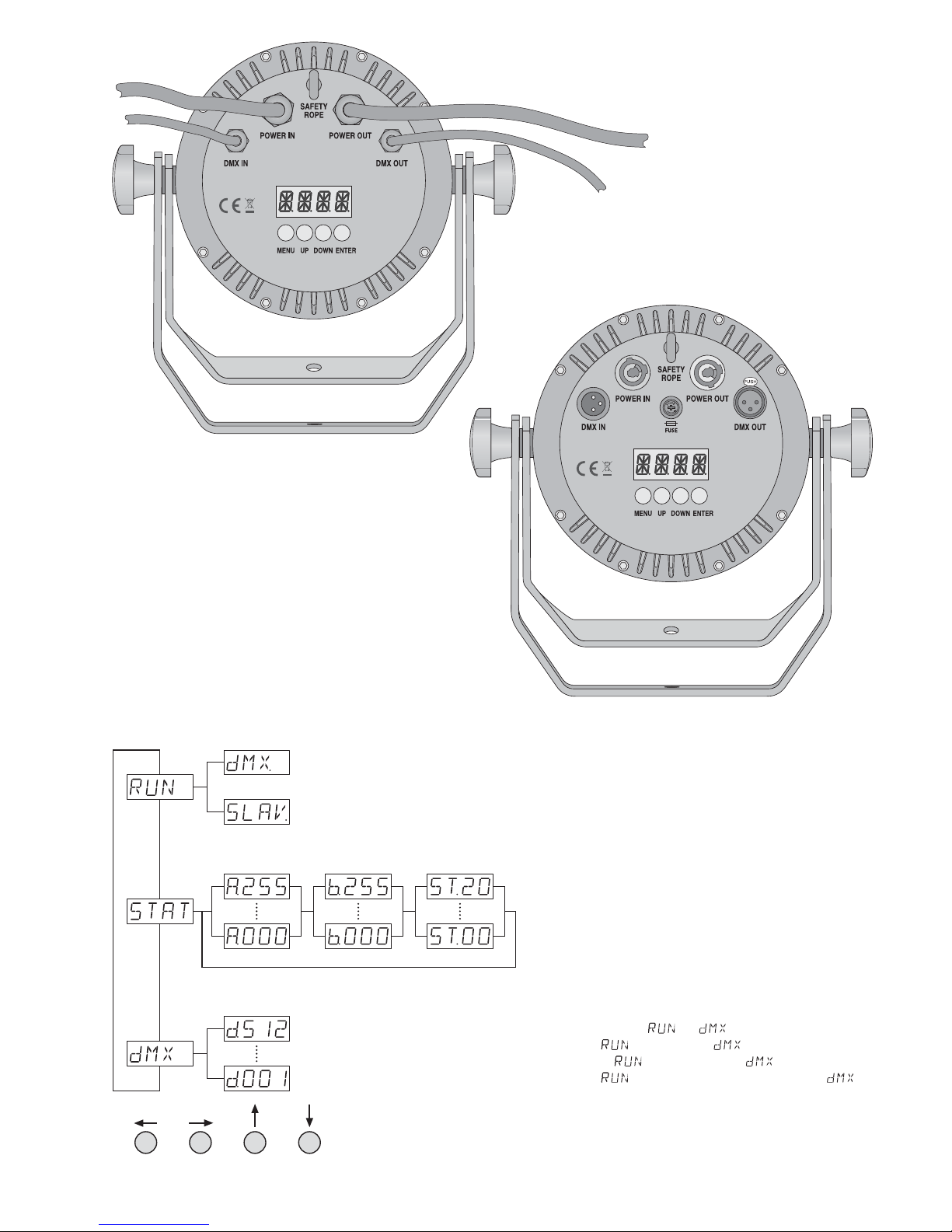
MENU UP DOWNENTER
Eigenständiger Betrieb:
A = Helligkeit kaltes Weiß
b = Helligkeit warmes Weiß
ST= Blitzfrequenz
Independent operation:
A = brightness cool white
b = brightness warm white
ST = flash rate
Fonctionnement indépendant :
A = luminosité blanc froid
b = luminosité blanc chaud
ST = fréquence des éclairs
Funzionamento autonomo:
A = luminosità bianco freddo
b = luminosità bianco caldo
ST= frequenza lampi
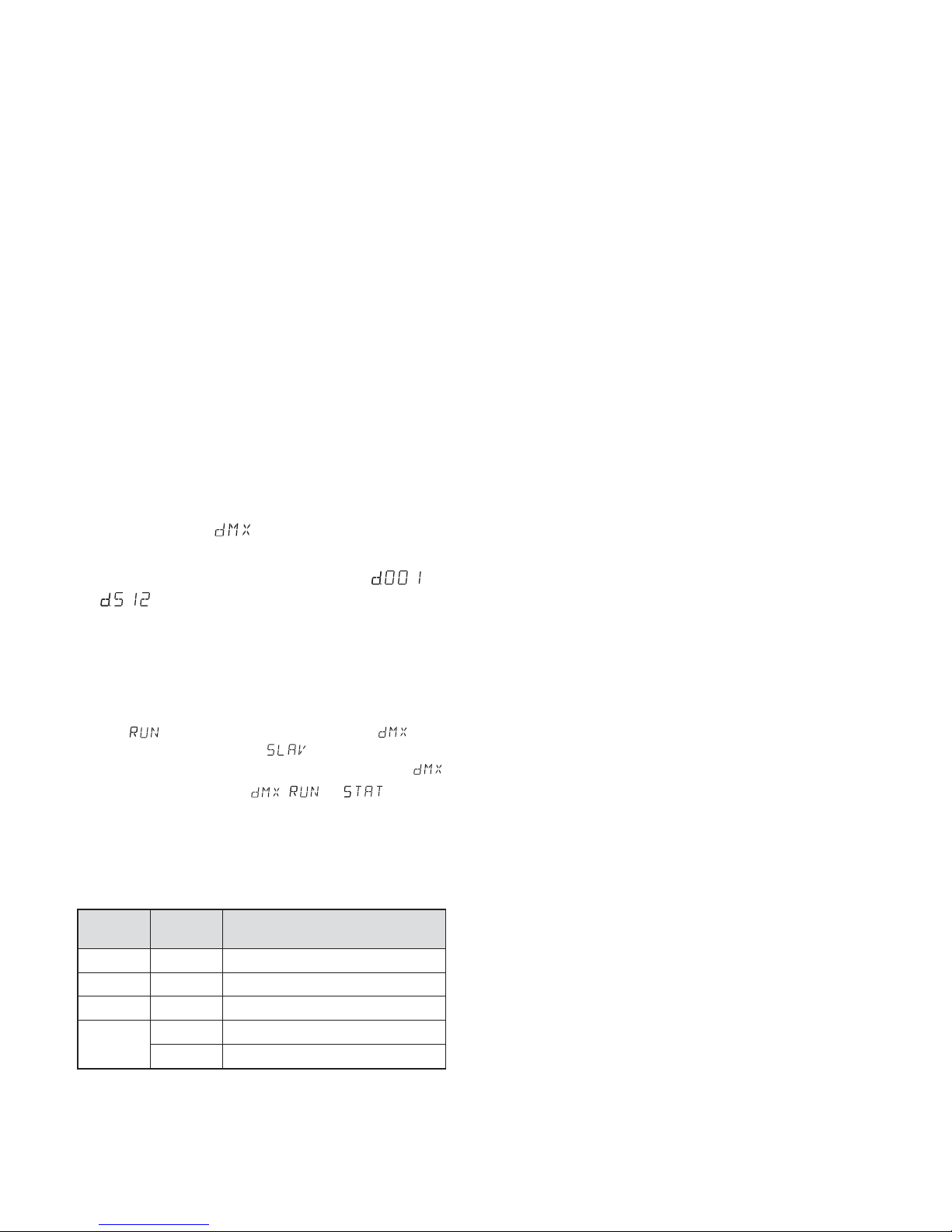
Menüstruktur • Menu structure
Structure du menu • Struttura del menù
DMX-Steuerung
DMX control
Gestion DMX
Comando DMX
Master-Gerät • Master unit
Appareil Master • Apparecchio master
Slave-Gerät • Slave unit
Appareil Slave • Apparecchio slave
für den Master/Slave-Betrieb
for master / slave mode
pour le mode Master / Slave
per il funzionamento master / slave
Für den DMX-Betrieb muss der Menüpunkt auf eingestellt sein!
For the DMX mode, the menu item must be set to !
Pour le mode DMX, le point de menu doit être réglé sur !
Per il funzionamento DMX, la voce del menu deve essere impostata a !
PARC-100 / CTW
ODC-100 / CTW

3
Deutsch . . . . . . . . . . . . . . . . . . Seite 4
English . . . . . . . . . . . . . . . . . . . Page 8
Français . . . . . . . . . . . . . . . . . . Page 12
Italiano . . . . . . . . . . . . . . . . . . Pagina 16
Nederlands . . . . . . . . . . . . . . . Pagina 20
Español . . . . . . . . . . . . . . . . . . Página 24
Polski . . . . . . . . . . . . . . . . . . . . Strona 28
Dansk . . . . . . . . . . . . . . . . . . . . Sida 32
Svenska . . . . . . . . . . . . . . . . . . Sidan 33
Suomi . . . . . . . . . . . . . . . . . . . . Sivulta 34
ELECTRONICS FOR SPECIALISTS ELECTRONICS FOR SPECIALISTS ELECTRONICS FOR SPECIALISTS ELECTRONICS FOR SPECIALISTS
4
Deutsch
DMX-LED-Scheinwerfer
Die Bedienung des Geräts ist einfach und auf
Bediener mit Grundkenntnissen in der DMXSteuerung ausgerichtet. Bitte lesen Sie trotzdem die Anleitung vor dem Betrieb gründlich
durch und heben Sie sie für ein späteres Nachlesen auf. Auf der Seite 2 sind die Modelle
ODC-100 / CTW und PARC-100 / CTW sowie die
Menüstruktur abgebildet.
1 Einsatzmöglichkeiten
Dieser LED-Scheinwerfer dient zur Beleuchtung
z. B. auf Bühnen, in Diskotheken und Festsälen.
Als Lichtquelle ist eine lichtstarke COB-LED eingesetzt (COB = Chip-on-Board-Techno logie):
Viele LED-Chips sind eng auf einer Leiterplatte
untergebracht, sodass eine gleichmäßige Lichtverteilung erreicht wird. Die Chip-LEDs sind je
zur Hälfe für ein warmes und ein kaltes Weiß
ausgelegt. Durch Ändern deren Helligkeitsverhältnisses lässt sich die Farbtemperatur des
Lichtstrahls zwischen 2700 K und 5600 K einstellen.
Der Scheinwerfer ist für die Steuerung über
ein DMX-Lichtsteuergerät ausgelegt (4 DMXSteuerkanäle), kann aber auch eigenständig
ohne Steuergerät betrieben werden. Der ODC100 / CTW ist durch seine wetterfeste Ausführung (IP 66) auch im Außenbereich einsetzbar.
2 Hinweise
für den sicheren Gebrauch
Das Gerät entspricht allen relevanten Richtlinien
der EU und ist deshalb mit
gekennzeichnet.
G
Das Modell PARC-100 / CTW
darf nur im Innenbereich gesetzt werden. Schützen Sie es
vor Tropf- und Spritzwasser, hoher Luftfeuchtigkeit und Hitze (zulässiger Einsatztemperaturbereich 0 bis 40 °C).
Das Modell
ODC-100 / CTW ist für den Außen-
bereich geeignet
(zulässiger Einsatztempera-
turbereich
-
20 bis +40 °C).
G
Ziehen Sie sofort den Netzstecker aus der
Steckdose,
1. wenn sichtbare Schäden am Gerät oder
am Netzkabel vorhanden sind,
2. wenn nach einem Sturz oder Ähnlichem
der Verdacht auf einen Defekt besteht,
3. wenn Funktionsstörungen auftreten.
Geben Sie das Gerät in jedem Fall zur Reparatur in eine Fachwerkstatt.
G
Ziehen Sie den Netzstecker nie am Kabel aus
der Steckdose, fassen Sie immer am Stecker
an.
G
Nur ODC-100 / CTW: Ein beschädigtes Netz kabel darf nur durch eine Fachwerkstatt er setzt werden.
G
Wird das Gerät zweckentfremdet, nicht sicher
montiert, nicht richtig angeschlossen, falsch
bedient oder nicht fachgerecht repariert, kann
keine Haftung für daraus resultierende Sachoder Personenschäden und keine Garantie
für das Gerät übernommen werden.
3 Inbetriebnahme
3.1 Montage
G
Platzieren Sie das Gerät so, dass im Betrieb
eine ausreichende Luftzirkulation gewährleistet ist. Die Kühlrippen des Gehäuses dürfen
auf keinen Fall abgedeckt werden.
G
Der Abstand zum angestrahlten Objekt sollte
mindestens 50 cm betragen.
1. Den Scheinwerfer über die Montagebügel
befestigen, z. B. mit einer stabilen Montage schraube oder einer Lichtstrahler-Halterung
(C-Haken) an einer Traverse. Zum Ausrichten des Scheinwerfers die zwei Feststellschrauben der Montagebügel lösen. Die
gewünschte Neigung des Scheinwerfers einstellen und die Schrauben wieder festziehen.
WARNUNG Das Gerät wird mit lebensgefähr -
licher Netzspannung versorgt.
Nehmen Sie deshalb nie selbst
Eingriffe am Gerät vor. Es be steht die Gefahr eines elektrischen Schlages.
Soll das Gerät endgültig aus dem
Betrieb genommen werden, übergeben Sie es zur umweltgerechten Entsorgung einem örtlichen Recycling betrieb.
WARNUNG Wird das Gerät an einer Stelle
installiert, unter der sich Personen
aufhalten können, muss es zu -
sätzlich gesichert werden, z. B.
durch ein Fangseil. Das Fangseil durch die
Sicherheitsöse an der Geräterückseite führen
und so befestigen, dass der Fallweg des
Geräts nicht mehr als 20 cm betragen kann.
5
Deutsch
2. Alternativ lässt sich der Scheinwerfer auch
frei aufstellen: Die Montagebügel so unter
dem Scheinwerfer spreizen, dass sie als
Ständer dienen. Die Feststellschrauben da nach festdrehen.
3.2 Torblende
Um den Lichtstrahl einzuengen, lässt sich die
als Zubehör erhältliche Torblende PARC-100B
an der Vorderseite festschrauben.
3.3 Stromversorgung
Mit dem Anschluss des Scheinwerfers ans Stromnetz ist er eingeschaltet. Das Display zeigt den
zuletzt gewählten Menüpunkt und erlischt nach
30 s. Sobald eine Taste (MENU, UP, DOWN oder
ENTER) gedrückt wird, leuchtet es wieder für 30 s.
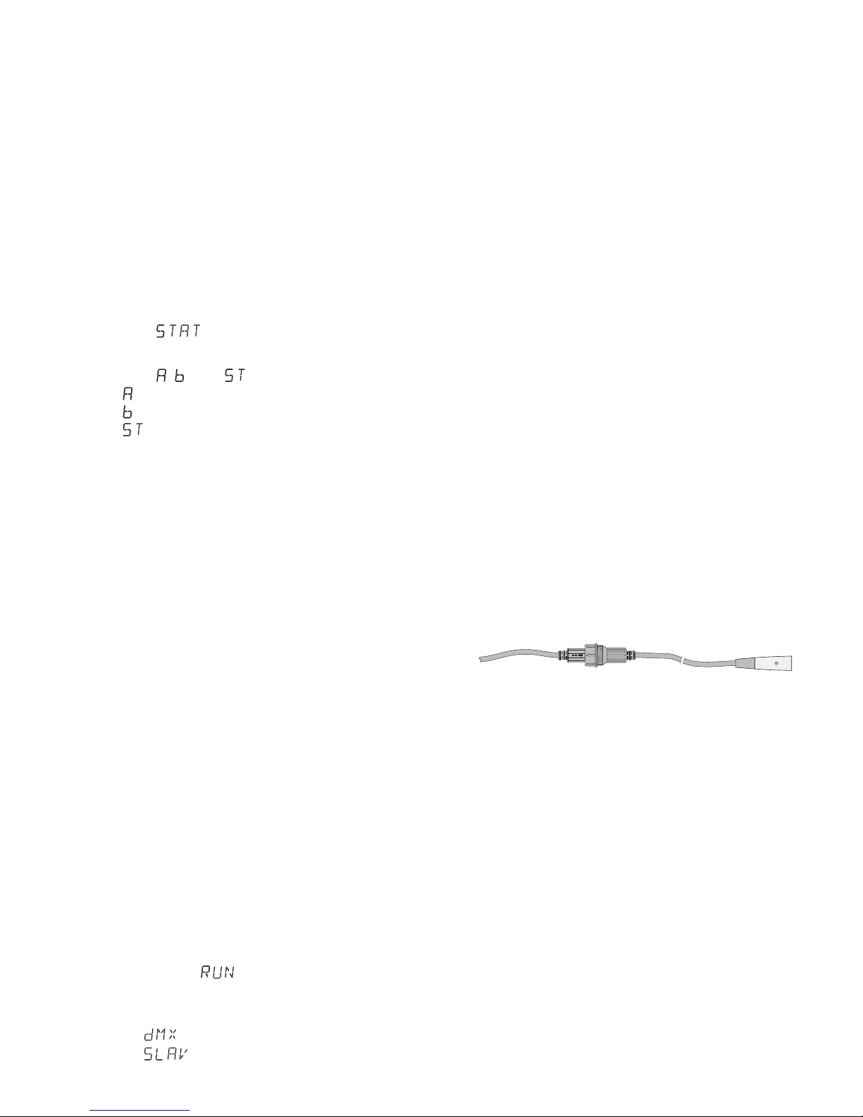
3.3.1 ODC-100 / CTW
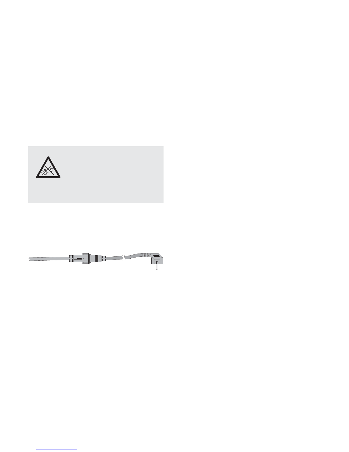
Den Stecker (A) des Kabels POWER IN in die
Kupplung (B) des beiliegenden Netzkabels stecken. Den Stecker und die Kupplung mit der
Überwurfmutter zusammenschrauben.
Netzanschluss ODC-100 / CTW
VORSICHT! Das Kabel POWER OUT führt
Netzspannung. Ist kein weiteres Gerät an den
Kabeln POWER OUT und DMX OUT angeschlossen, unbedingt die beiliegenden Schutzkappen auf die Kupplungen schrauben.
Den Netzstecker in eine Steckdose (230 V~/
50 Hz) stecken.
Stromversorgung mehrerer ODC-100 / CTW
Werden mehrere ODC-100 / CTW eingesetzt,
können die Geräte zur Stromversorgung mitein ander verbunden werden. Das erste Gerät vorerst noch nicht an eine Steckdose an schließen.
1) Das 1. Gerät über die Kupplung des Kabels
POWER OUT mit dem Stecker (A) des Kabels POWER IN des 2. Geräts verbinden.
Genauso das 2. Gerät mit dem 3. Gerät. verbinden usw., bis alle Geräte in einer Kette angeschlossen sind.
Sollten die Netzverbindungskabel zwischen den Geräten zu kurz sein, passende
Verlängerungskabel verwenden, z.B.:
ODP-34AC Länge 2 m oder
ODP-34AC / 10 Länge 10 m.
VORSICHT! Der Gesamtstrom in den An schlusskabeln darf 10 A nicht überschreiten,
sonst kann durch Überlastung ein Kabelbrand entstehen. Darum nur maximal 19 Ge räte ODC-100 / CTW miteinander verbinden.
2) Am letzten Gerät auf die Kupplung des Kabels
POWER OUT die beiliegende Schutzkappe
schrauben. Das Kabel führt Netzspannung!
3) Den Netzstecker des ersten Geräts in eine
Steckdose (230 V~ / 50 Hz) stecken.
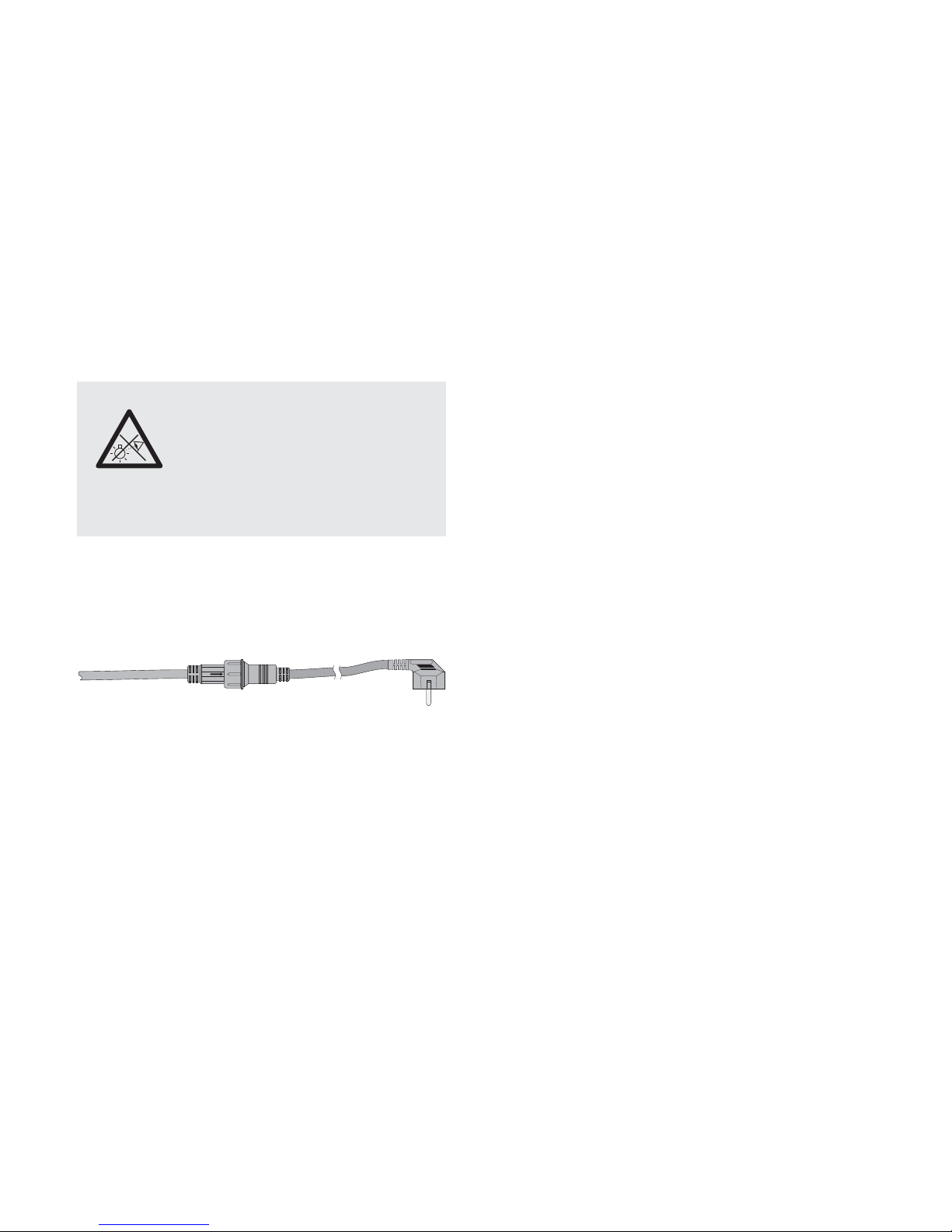
3.3.2 PARC-100 / CTW
Zur Stromversorgung ist das Gerät mit Powercon
®
-Anschlüssen ausgestattet.
VORSICHT! Ein Powercon-Stecker darf nicht
unter Spannung hineingesteckt oder herausgezogen werden. Stellen Sie darum immer zuerst
die Powercon-Verbindung her, dann die Verbindung zur Netzsteckdose und trennen Sie die
Verbindung zur Netzsteckdose immer vor der
Powercon-Verbindung.
Die Netzbuchse POWER IN mit dem beiliegenden Netzkabel an eine Steckdose (230 V~/ 50 Hz)
anschließen. Den blauen Powercon-Stecker des
Kabels nach dem Einstecken in die Netzbuchse
zum Einrasten nach rechts drehen. Zum späteren
Herausziehen den Sicherungsriegel am Stecker
zurückziehen und den Stecker nach links drehen.
Stromversorgung mehrerer PARC-100 / CTW
Werden mehrere PARC-100 / CTW verwendet,
lässt die Buchse POWER OUT des ersten
Geräts mit der Netzbuchse POWER IN des
zweiten Geräts verbinden. Dazu wird ein Netzkabel mit Powercon-Steckern (NAC-3FCB und
NAC-3FCA) benötigt. Das zweite Gerät ge nauso mit dem dritten Gerät verbinden usw., bis
alle Geräte in einer Kette angeschlossen sind.
Auf diese Weise dürfen maximal 19 Geräte miteinander verbunden werden. Die Buchse
POWER OUT kann auch zur Stromversorgung
anderer (Lichteffekt-) Geräte genutzt werden.
VORSICHT! Die Kabel und der Netzstecker dürfen nicht mit einem Strom über 10 A belastet
werden, sonst kann durch Überlastung ein
Brand entstehen.
WARNUNG Blicken Sie nicht für längere Zeit
direkt in die Lichtquelle, das kann
zu Augenschäden führen.
Beachten Sie, dass sehr schnelle
Lichtwechsel bei fotosensiblen
Menschen und Epileptikern epileptische Anfälle auslösen können!
230V~
POWER IN AB
6
Deutsch
4 Bedienung
Die Wahl des Betriebsmodus und der Einstellfunktionen erfolgt über ein Menü mit den Tasten
MENU, ENTER, UP und DOWN. Die Abbildung
3 auf der Seite 2 zeigt, wie die Modi und Funktionen über das Menü angewählt und vom Display angezeigt werden.
4.1 Eigenständiger Betrieb
Hierfür lässt sich am Scheinwerfer die Helligkeit
für kaltes Weiß und für warmes Weiß einstellen,
die Stroboskop-Funktion einschalten und die
Blitzfrequenz einstellen.
1) Die Taste MENU so oft drücken, bis das Display anzeigt.
2) Die Taste ENTER drücken. Das Display zeigt
jetzt , oder und eine Zahl.
= Helligkeit kaltes Weiß (0 – 255)
= Helligkeit warmes Weiß (0 – 255)
= Blitzfrequenz (0 – 20 Hz) des Stroboskops
3) Mit der Taste ENTER die drei Einstellfunktionen nacheinander anwählen und mit der Taste
UP oder DOWN jeweils die Helligkeit bzw. die
Blitzfrequenz einstellen. Die Farbtemperatur
des Lichtstrahls ergibt sich durch das Helligkeitsverhältnis von kaltem zu warmem Weiß.
Hinweis: Vor dem Ausschalten des Scheinwerfers den
Menüpunkt für die Helligkeit oder Blitzfrequenz nicht
mit der Taste MENU verlassen. Anderenfalls bleibt der
Scheinwerfer nach dem Wiedereinschalten dunkel.
4.2 Synchrone Steuerung mehrerer
Scheinwerfer (Master-Slave-Modus)
Es lassen sich mehrere ODC- und PARC-100 /
CTW (auch gemischt) zusammenschließen. Die
Einstellungen für Helligkeit und Blitzfrequenz
am Hauptgerät (Master) werden dann automatisch auf die Nebengeräte (Slave) übertragen.
1) Die Scheinwerfer über die DMX-Anschlüsse
miteinander zu einer Kette verbinden. Siehe
dazu Kapitel 4.3.1 „Anschluss“, jedoch ohne
den Bedienschritt 1 zu beachten.
2) Das Hauptgerät auf den Master-Modus einstellen und alle Nebengeräte auf den SlaveModus:
a) Die Taste MENU so oft drücken, bis das
Display anzeigt.
b) Die Taste ENTER drücken und mit der
Taste UP oder DOWN wählen:
= Master-Modus für das Hauptgerät
= Slave-Modus für die Nebengeräte
3) Am Hauptgerät die gewünschte Helligkeit
und Blitzfrequenz einstellen.
4.3 Betrieb mit einem DMX-Steuergerät
Zur Bedienung über ein DMX-Lichtsteuergerät
(z. B. DMX-1440 oder DMX-510USB von „img
Stage Line“) verfügt der Scheinwerfer über vier
DMX-Steuerkanäle. DMX ist die Abkürzung für
Digital Multiplex und bedeutet digitale Steuerung von mehreren DMX-Geräten über eine
gemeinsame Steuerleitung. Die Funktionen der
Kanäle und die DMX-Werte sind im Kapitel 4.3.3
(Abb. 6) angegeben.
4.3.1 Anschluss
Für die DMX-Signalübertragung sollten spezielle Kabel verwendet werden (z. B. CDMXN-…
von „img Stage Line“). Bei Leitungslängen ab
150 m oder bei der Steuerung von mehr als 32
Geräten über einen DMX-Ausgang wird grundsätzlich das Zwischenschalten eines DMX-Aufholverstärkers empfohlen (z. B. SR-103DMX).
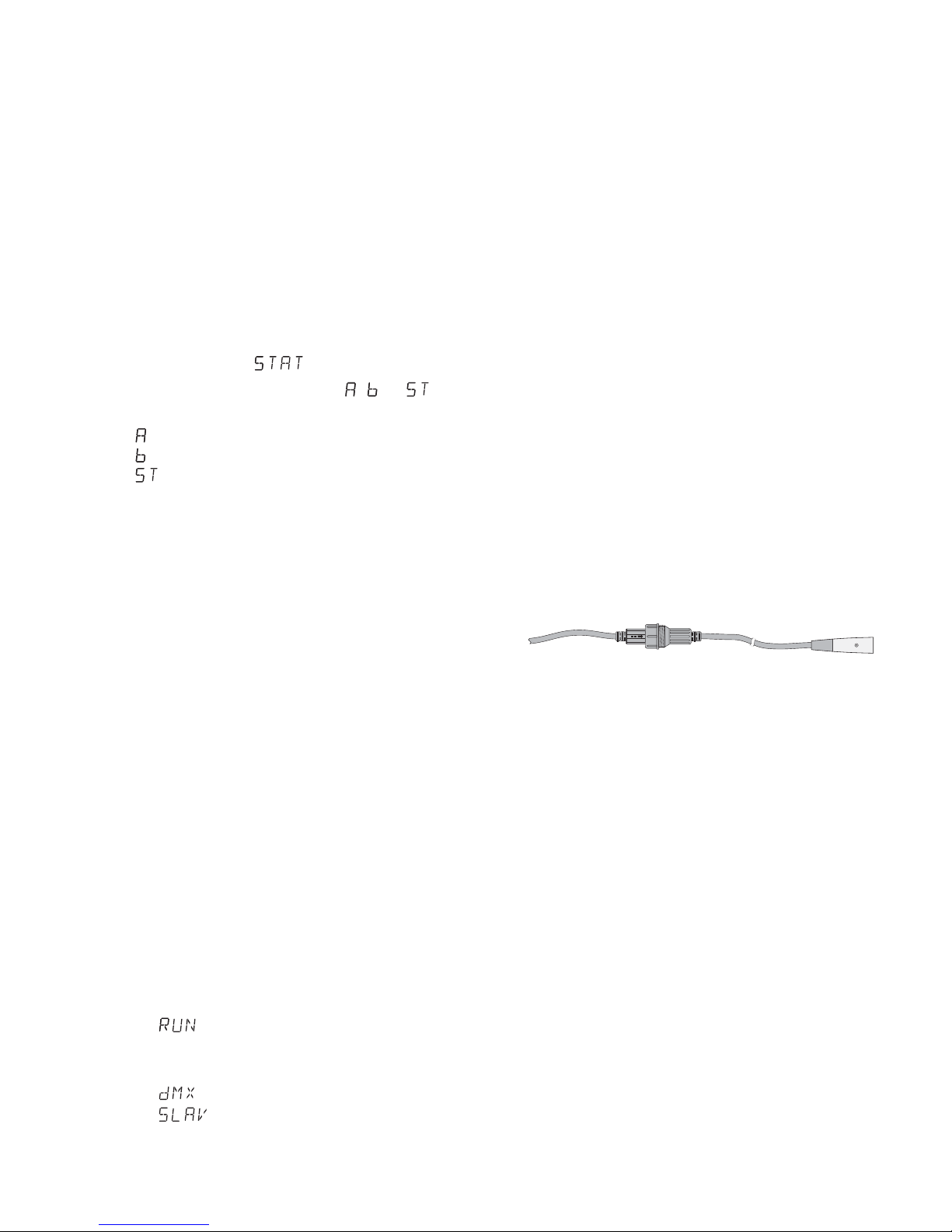
1) Den Eingang DMX IN mit dem DMX-Ausgang des Lichtsteuergeräts oder eines DMXgesteuerten Geräts verbinden.
Bei dem Modell ODC-100 / CTW den Stecker (C) der Leitung DMX IN in die Kupplung
(D) der beiliegenden Leitung mit dem XLRStecker stecken. Den Stecker und die Kupplung mit der Überwurfmutter zu sammenschrauben.
DMX-Anschluss ODC-100 / CTW
Den XLR-Stecker über ein Verlängerungs kabel an den DMX-Ausgang des Lichtsteuergeräts anschließen oder, wenn weitere DMXgesteuerte Geräte verwendet werden, an
den DMX-Ausgang des letzten DMX-gesteuerten Geräts.
2) Den Ausgang DMX OUT mit dem DMX-Eingang des nächsten DMX-Geräts verbinden.
Dessen Ausgang wieder mit dem Eingang
des nachfolgenden DMX-Geräts verbinden
usw., bis alle DMX-gesteuerten Geräte in
einer Kette angeschlossen sind.
Sind beim Verbinden von mehreren ODC100 / CTW miteinander die DMX-Verbindungskabel zwischen den Geräten zu kurz, passende Verlängerungskabel verwenden, z. B.
ODP-34DMX Länge 2 m oder
ODP-34DMX / 10 Länge 10 m.
DMX IN C
D

3) Um Störungen bei der Signalübertragung auszuschließen, sollte bei langen Leitungen oder
bei einer Vielzahl von hintereinandergeschalteten Geräten der DMX-Ausgang des letzten
DMX-Geräts der Kette mit einem 120-ΩWiderstand (> 0,3 W) abgeschlossen werden:
In die DMX-Ausgangsbuchse einen entsprechenden Ab schlussstecker (z. B. DLT-123)
stecken.
Um den DMX-Ausgang des ODC100/CTW abzuschließen, ist es am einfachsten, ein Verlängerungskabel ODP-34DMX
aufzutrennen und den Widerstand mit den
Pins 2 und 3 des Steckers zu verbinden. Den
Stecker mit dem Widerstand in die Kupplung
des Kabels DMX OUT stecken. Wird kein
Abschlusswiderstand benötigt, auf die Kupplung des Kabels die beiliegende Schutz-
kappe schrauben.
4.3.2 Startadresse einstellen
Um alle am Lichtsteuergerät angeschlossenen
DMX-Geräte separat bedienen zu können,
muss jedes Gerät eine eigene Startadresse
erhalten. Soll der erste DMX-Kanal des Scheinwerfers vom Lichtsteuergerät z. B. über die
DMX-Adresse 17 gesteuert werden, am Scheinwerfer die Startadresse 17 einstellen. Alle weiteren DMX-Kanäle des Scheinwerfers sind dann
automatisch den darauffolgenden Adressen
zugeordnet (z. B. bei der Startadresse 17 die
Adressen 18 – 20).
1) Die Taste MENU so oft drücken, bis das Display anzeigt.
2) Die Taste ENTER drücken. Das Display zeigt
die eingestellte Startadresse an ( …
).
3) Mit den Tasten UP und DOWN die ge wünschte Adresse einstellen. Der Scheinwerfer lässt sich jetzt mit dem Lichtsteuergerät bedienen.
Hinweise
1. Sollte die DMX-Steuerung nicht funktionieren, den
Menüpunkt aufrufen und die Taste ENTER
drücken. Es muss angezeigt werden. Wird
angezeigt, mit der Taste UP oder DOWN auf
umschalten.
2. Zeigt das Display den Menüpunkt , oder
, blinkt ganz rechts der Punkt, wenn DMX-
Signale am DMX-Eingang anliegen.
4.3.3 DMX-Kanäle und -Funktionen
DMX-Übersicht
5 Reinigung des Geräts
Die Scheibe vor der LED sollte je nach Verschmutzung in regelmäßigen Abständen gereinigt werden. Nur dann kann das Licht in maximaler Helligkeit abgestrahlt werden. Zum
Säubern den Netzstecker aus der Steckdose
ziehen. Nur ein weiches, sauberes Tuch und ein
Glaseinigungsmittel verwenden.
Zum Reinigen der anderen Gehäuseteile
des PARC-100 / CTW nur ein weiches, sauberes
Tuch benutzen. Auf keinen Fall eine Flüssigkeit
verwenden, die könnte in das Gerät laufen und
es beschädigen. Das wettergeschützte Gehäuse
des ODC-100 / CTW kann auch feucht mit einem
milden Reinigungsmittel ge säubert werden.
6 Technische Daten
Datenprotokoll: . . . . . . . . . . DMX 512
Anzahl der DMX-Kanäle: . . 4
Lichtquelle: . . . . . . . . . . . . . COB-LED
Leistungsaufnahme: . . . . 100 W
Abstrahlwinkel: . . . . . . . . 60°
Farbtemperatur: . . . . . . . einstellbar
2700 K – 5600 K
DMX-Anschlüsse: . . . . . . . XLR, 3-polig
Pinbelegung: . . . . . . . . . Pin 1 = Masse
Pin 2 = DMX
-
Pin 3 = DMX+
Stromversorgung: . . . . . . . 230 V~ / 50 Hz
Leistungsaufnahme: . . . . . max. 120 VA
Gehäuseschutzart: . . . . . . . IP 66 (nur ODC-)
Maße ohne Montagebügel: ∅ 185 × 250 mm
Gewicht: . . . . . . . . . . . . . . . 6,5 kg
Änderungen vorbehalten.
DMXKanal
DMX-
Wert
Funktion
1
000 – 255
Helligkeit 0 % © 100 %
2
000 – 255
Grundhelligkeit kaltes Weiß
3
000 – 255
Grundhelligkeit warmes Weiß
4
000 – 010
Stroboskop aus
011 – 255
Stroboskop langsam © schnell
7
Deutsch
Diese Bedienungsanleitung ist urheberrechtlich für MONACOR®INTERNATIONAL GmbH & Co. KG ge schützt.
Eine Reproduktion für eigene kommerzielle Zwecke – auch auszugsweise – ist untersagt.
DMX LED Spotlight
Operation of the spotlight is easy for users with
basic knowledge in DMX control. However,
please read the instructions carefully prior to
operation and keep them for later reference.
On page 2, you will find the spotlights ODC100 / CTW and PARC-100 / CTW together with
the menu structure.
1 Applications
This LED spotlight is used for illumination, e. g.
on stage, in discotheques and function rooms.
The light source is a powerful COB LED (COB =
chip-on-board technology): Many individual
LED chips are densely packed on a PCB to provide a uniform light distribution. Half of the LED
chips are designed for warm white, and half of
the LED chips are designed for cool white.
Change the brightness ratio between cool white
and warm white to set the colour temperature of
the light beam to a value between 2700 K and
5600 K.
The spotlight is designed for control via a
DMX light controller (4 DMX control channels),
but it can also be operated independently without a controller. The ODC-100 / CTW is weatherproof (IP 66) and therefore also suited for outdoor applications.
2 Safety Notes
The spotlight corresponds to all relevant directives of the EU and is therefore marked with
.
G
The spotlight PARC-100/CTW is suitable for
indoor use only. Protect it against dripping water and splash water, high air humidity and
heat (admissible ambient temperature range:
0 – 40 °C).
The spotlight ODC-100/CTW is suitable for
outdoor applications (admissible ambient temperature range:
-
20 to +40 °C).
G
Immediately disconnect the mains plug from
the socket
1. if the spotlight or the mains cable is visibly
damaged,
2. if a defect might have occurred after the
spotlight was dropped or suffered a similar
accident,
3. if malfunctions occur.
In any case the spotlight must be repaired by
skilled personnel.
G
Never pull the mains cable to disconnect the
mains plug from the socket, always seize the
plug.
G
For ODC-100 / CTW only: A damaged mains cable must be replaced by skilled personnel only.
G
No guarantee claims for the spotlight and no
liability for any resulting personal damage or
material damage will be accepted if the spotlight is used for other purposes than originally
intended, if it is not safely installed or not correctly connected or operated, or if it is not repaired in an expert way.
3 Setting the Spotlight
into Operation
3.1 Installation
G
Always position the spotlight in such a way to
ensure sufficient air circulation during operation. Never cover the cooling fins of the housing.
G
Always keep a minimum distance of 50 cm to
the illuminated object.
1. Install the spotlight via its mounting brackets,
e. g. with a stable mounting screw or a support for lighting units (C hook) on a cross bar.
To align the spotlight, release the two
locking screws of the mounting brackets.
Adjust the desired inclination of the spotlight
and fasten the screws.
2. Alternatively, set up the spotlight on its own:
Fold out the mounting brackets underneath
WARNING When the spotlight is installed at a
place where people may walk or sit
under it, additionally secure it, e. g.
via a safety rope. Guide the safety
rope through the eyebolt on the rear of the
spotlight and fasten it in such a way that the
maximum falling distance of the spotlight will
not exceed 20 cm.
If the spotlight is to be put out of operation definitively, take it to a local recycling plant for a disposal which is not
harmful to the environment.
WARNING The spotlight uses dangerous
mains voltage. Leave servicing to
skilled personnel; inexpert handling
may result in electric shock.
8
English
the spotlight and use them as a stand. Then
fasten the locking screws.
3.2 Barn doors
To reduce the light beam angle, optional barn
doors are available: PARC-100B. Fasten the
barn doors to the front of the spotlight.
3.3 Power supply
When the spotlight has been connected to the
mains, it is switched on. The display will show
the menu item most recently selected and go
out after 30 seconds. As soon as a button
(MENU, UP, DOWN or ENTER) is pressed, the
display will light up again for 30 seconds.
3.3.1 ODC-100 / CTW
Connect the plug (A) of the cable POWER IN to
the inline jack (B) of the mains cable provided.
Then fasten the nut to secure this connection.
Mains connection ODC-100 / CTW
CAUTION! The cable POWER OUT carries
mains voltage. If no further unit is connected to
the cables POWER OUT and DMX OUT, always
screw the protective covers supplied onto the
inline jacks.
Connect the mains plug to a socket (230 V~/
50 Hz).
Power supply
of multiple ODC-100 / CTW spotlights
If multiple ODC-100 / CTW spotlights are used,
the units can be interconnected for power supply. For the time being, do not yet connect the
first unit to a mains socket.
1) Use the inline jack of the cable POWER OUT
to connect the first unit to the plug (A) of the
cable POWER IN of the second unit. Proceed in the same way to connect the second
unit to the third one etc. until all units have
been connected in a chain.
If the mains connection cables between
the spotlights are too short, use suitable
extension cables, e. g.
ODP-34AC length: 2 m or
ODP-34AC / 10 length: 10 m
CAUTION! To reduce the risk of cable fire
caused by overload, the total current in the
connection cables must not exceed 10 A.
Therefore, do not interconnect more than 19
ODC-100 / CTW spotlights.
2) On the last spotlight, screw the protective
cover supplied onto the inline jack of the
cable POWER OUT. The cable carries mains
voltage!
3) Connect the mains plug of the first spotlight
to a mains socket (230 V~ / 50 Hz).
3.3.2 PARC-100 / CTW
For power supply, the unit is equipped with Powercon
®
connections.
CAUTION! Never connect or disconnect a Powercon plug while voltage is applied. Always
make the Powercon connection before making
the mains connection. When disconnecting,
always disconnect the mains connection before
disconnecting the Powercon connection.
Connect the mains jack POWER IN to a mains
socket (230 V~ / 50 Hz) via the mains cable provided. Connect the blue Powercon plug of the
cable to the mains jack, and then turn the plug
clockwise until it locks. To remove the plug, pull
back the safety latch of the plug and turn the
plug counter-clockwise.
Power supply
of multiple PARC-100 / CTW spotlights
If multiple PARC-100 / CTW spotlights are used,
the jack POWER OUT of the first spotlight can
be connected to the mains jack POWER IN of
the second spotlight. For this, a mains cable with
Powercon plugs (NAC-3FCB and NAC-3FCA) is
required. Proceed in the same way to connect
the second spotlight to the third spotlight etc.
until all spotlights have been connected in a
chain. Thus, up to 19 spotlights can be interconnected. The jack POWER OUT can also be used
for power supply of other (light effect) units.
CAUTION! To reduce the risk of fire caused by
overload, the current load of the cables and the
mains plug must not exceed 10 A.
230V~
POWER IN AB
WARNING To prevent damage to your eyes,
never look directly into the light
source for any length of time.
Please note that fast changes
in lighting may trigger epileptic
seizures with photosensitive persons or persons with epilepsy!
9
English
10
English
4 Operation
The operating modes and the setting functions
are selected via a menu by means of the buttons
MENU, ENTER, UP and DOWN. Figure 3 on
page 2 shows the selection of the modes and
functions via the menu and the indications on
the display.
4.1 Independent operation
For independent operation, it is possible to set
the brightness for cool white and warm white, to
activate the stroboscope function and to set the
flash rate on the spotlight.
1) Press the button MENU repeatedly until the
display shows .
2) Press the button ENTER. , or and a
number will appear on the display.
= brightness cool white (0 – 255)
= brightness warm white (0 – 255)
= flash rate (0 – 20 Hz) of the stroboscope
3) Use the button ENTER to select the three
setting functions one after the other and then
use the button UP or DOWN to set the brightness or flash rate. The colour temperature of
the light beam is defined by the brightness
ratio between cool white and warm white.
Note: Do not use the button MENU to exit the menu
item for the brightness or the flash rate before switching off the spotlight. If you do, the spotlight will remain
dark when it is switched on again.
4.2 Synchronous control of multiple
spotlights (master / slave mode)
Multiple spotlights ODC-100 / CTW and PARC100 / CTW (also a combination of both) may be
combined. The brightness and flash rate settings made at the master unit will be automatically transferred to the slave units.
1)
Connect the spotlights with each other in a
chain, using the DMX connections; please refer
to chapter 4.3.1, “Connection”, skipping step 1.
2) Set the master unit to the master mode and
all slave units to the slave mode:
a) Press the button MENU repeatedly until
appears on the display.
b) Press the button ENTER and then use the
button UP or DOWN to select:
= master mode for the master unit
= slave mode for the slave units
3) At the master unit, set the brightness and
flash rate desired.
4.3 Operation with a DMX controller
For operation via a DMX light controller (e. g.
DMX-1440 or DMX-510USB from “img Stage
Line”), the spotlight is equipped with four DMX
control channels. DMX stands for Digital Multi-
plex and means digital control of multiple DMX
units via a common control cable. The functions
of the channels and the DMX values can be
found in chapter 4.3.3 (fig. 6).
4.3.1 Connection
For DMX signal transmission, special cables
should be used (e. g. CDMXN-… from “img
Stage Line”). For cable lengths exceeding
150 m or for control of more than 32 units via a
single DMX output, it is generally recommended
to insert a DMX level matching amplifier (e. g.
SR-103DMX).
1) Connect the input DMX IN to the DMX output
of the light controller or to the DMX output of
another DMX-controlled unit.
For the spotlight ODC-100 / CTW, connect
the plug (C) of the cable DMX IN to the inline
jack (D) of the supplied cable equipped with
an XLR plug. Then fasten the nut to secure
this connection.
DMX connection ODC-100 /CTW
Use an extension cable to connect the XLR
plug to the DMX output of the light controller
or, if additional DMX-controlled units are
used, to the DMX output of the last DMX-controlled unit.
2) Connect the output DMX OUT to the DMX
input of the second DMX unit. Connect the
output of the second DMX unit to the input of
the third DMX unit etc. until all DMX-controlled units have been connected in a chain.
If the DMX connection cables between
the units are too short when interconnecting
multiple ODC-100 / CTW spotlights, use suitable extension cables, e. g.
ODP-34DMX length: 2 m or
ODP-34DMX / 10 length: 10 m
3) To prevent interference in signal transmission, in case of long cables or a multitude of
units connected in series, terminate the DMX
output of the last DMX unit in the chain with a
120 Ω resistor (> 0.3 W): Connect a corre-
DMX IN C
D
11
English
All rights reserved by MONACOR®INTERNATIONAL GmbH & Co. KG. No part of this instruction manual may
be reproduced in any form or by any means for any commercial use.
sponding terminating plug (e. g. DLT-123 from
“img Stage Line”) to the DMX output jack.
The easiest way to terminate the DMX output of the ODC-100/CTW is to separate an extension cable ODP-34DMX and to connect the
resistor to the pins 2 and 3 of the plug. Connect the plug with the resistor to the inline jack
of the cable DMX OUT. If no terminating resistor is required, screw the protective cover
provided onto the inline jack of the cable.
4.3.2 Setting the start address
For separate control of all DMX units connected
to the light controller, each unit must have its
own start address. Example: If the first DMX
channel of the spotlight is to be controlled by the
light controller via DMX address 17, set the start
address on the spotlight to 17. All other DMX
channels of the spotlight will be automatically
assigned to the following addresses (i. e. the
addresses 18 – 20 for the start address 17).
1) Press the button MENU repeatedly until the
display shows .
2) Press the button ENTER. The display will
show the start address adjusted ( …
).
3) To set the desired address, press the buttons
UP and DOWN. Now the spotlight can be
operated via the light controller.
Notes
1. If the DMX control does not work, call up the menu
item and press the button ENTER. must
appear on the display. If appears on the display, use the button UP or DOWN to switch to .
2. When the menu item , or appears
on the display and DMX signals are available at
the DMX input, the dot at the right end of the display will flash.
4.3.3 DMX channels and functions
DMX overview
5 Cleaning the Spotlight
Clean the pane in front of the LED at regular
intervals depending on impurities. This is the
only way to ensure that light will be emitted at
maximum brightness. Before cleaning, dis-
connect the mains plug from the socket.
Only use a soft clean cloth and a glass cleaner.
For cleaning the other parts of the housing
of the PARC-100 / CTW, only use a soft clean
cloth. Never use any fluid; it may leak into the
spotlight and damage it.
The weatherproof housing of the ODC100 / CTW may also be cleaned with a damp
cloth and a mild detergent.
6 Specifications
Data protocol: . . . . . . . . . . . DMX 512
Number of DMX channels: . 4
Light source: . . . . . . . . . . . COB LED
Power consumption: . . . . 100 W
Beam angle: . . . . . . . . . . 60°
Colour temperature: . . . . adjustable
2700 K – 5600 K
DMX connections: . . . . . . . XLR, 3 poles
Pin assignment: . . . . . . . Pin 1 = ground
Pin 2 = DMX
-
Pin 3 = DMX+
Power supply: . . . . . . . . . . 230 V~ / 50 Hz
Power consumption: . . . . . 120 VA max.
Protection of housing: . . . . IP66 (ODC- only)
Dimensions w/o
mounting bracket: . . . . . . . ∅ 185 × 250 mm
Weight: . . . . . . . . . . . . . . . . 6.5 kg
Subject to technical modification.
DMX
channel
DMX
value
Function
1
000 – 255
brightness 0 % © 100 %
2
000 – 255
basic brightness cool white
3
000 – 255
basic brightness warm white
4
000 – 010
stroboscope off
011 – 255
stroboscope slow © fast
 Loading...