

IMG STAGE LINE PAK-415 Instruction Manual
AKTIVE PA- UND DJ-LAUTSPRECHERBOX
ACTIVE PA AND DJ SPEAKER SYSTEM
ENCEINTE ACTIVE PROFESSIONNELLE DJ
CASSA ACUSTICA ATTIVA PA E DJ
PAK-415 Best.-Nr. 24.3100
BEDIENUNGSANLEITUNG • INSTRUCTION MANUAL • MODE D’EMPLOI • ISTRUZIONI PER L’USO
INSTRUKCJA OBSLUGI • VEILIGHEIDSVOORSCHRIFTEN • CONSEJOS DE SEGURIDAD
SIKKERHEDSOPLYSNINGER • SÄKERHETSFÖRESKRIFTER • TURVALLISUUDESTA

2
Bevor Sie einschalten ...
Wir wünschen Ihnen viel Spaß mit Ihrem neuen Gerät von
„img Stage Line“. Dabei soll Ihnen diese Bedienungsanleitung helfen, alle Funktionsmöglichkeiten kennen zu lernen. Die Beachtung der Anleitung vermeidet außerdem
Fehlbedienungen und schützt Sie und Ihr Gerät vor eventuellen Schäden durch unsachgemäßen Gebrauch.
Den deutschen Text finden Sie auf den Seiten 4–6.
Before you switch on ...
We wish you much pleasure with your new “img Stage
Line” unit. With these operating instructions you will be
able to get to know all functions of the unit. By following
these instructions false operations will be avoided, and
possible damage to yourself and your unit due to improper use will be prevented.
You will find the English text on the pages 4 –6.
D
A
CH
GB
Przed uruchomieniem …
Życzymy zadowolenia z nowego produktu “ img Stage
Line”. Dzięki tej instrukcji obsługi będą Państwo w stanie
poznać wszystkie funkcje tego urządzenia. Stosując się
do instrukcji unikną Państwo błędów i ewentualnego
uszkodzenia urządzenia na skutek nieprawidłowego
użytkowania.
Tekst polski znajduje się na stronach 10–11.
Voordat u inschakelt ...
Wij wensen u veel plezier met uw nieuw toestel van “img
Stage Line”. Lees de veiligheidsvoorschriften, alvorens
het toestel in gebruik te nemen. Door de veiligheidsvoorschriften op te volgen zal een slechte werking vermeden
worden, en zal een eventueel letsel aan uzelf en schade
aan uw toestel tengevolge van onzorgvuldig gebruik
worden voorkomen.
U vindt de de veiligheidsvoorschriften op pagina 12.
PL
B
NL
Antes de cualquier instalación
Tenemos de agradecerle el haber adquirido un aparato
“img Stage Line” y le deseamos un agradable uso. Por
favor lee las instrucciones de seguridad antes del uso.
La observación de las instrucciones de seguridad evita
operaciones erróneas y protege Vd. y vuestro aparato
contra todo daño posible por cualquier uso inadecuado.
Las instrucciones de seguridad se encuentran en la
página 12.
Inden De tænder for apparatet ...
Vi ønsker Dem god fornøjelse med Deres nye “img
Stage Line” apparat. Læs oplysningerne for en sikker
brug af apparatet før ibrugtagning. Følg sikkerhedsoplysningerne for at undgå forkert betjening og for at beskytte Dem og Deres apparat mod skade på grund af forkert brug.
Sikkerhedsoplysningerne finder De på side 12.
E DK
Förskrift
Vi önskar dig mycket nöje med din nya enhet från “img
Stage Line”. Läs gärna säkerhetsinstruktionerna innan
du använder enheten. Genom att följa säkerhetsinstruktionerna kan många problem undvikas, vilket annars kan
skada enheten.
Du finner säkerhetsinstruktionerna på sidan 13.
S
FIN
Avant toute mise en service ...
Nous vous remercions d’avoir choisi un appareil “img
Stage Line” et vous souhaitons beaucoup de plaisir à
l’utiliser. Cette notice a pour objectif de vous aider à
mieux connaître les multiples facettes de l’appareil. En
outre, en respectant les conseils donnés, vous éviterez
toute mauvaise manipulation de sorte que vous-même et
votre appareil soient protégés de tout dommage.
La version française se trouve pages 7–9.
Prima di accendere ...
Vi auguriamo buon divertimento con il Vostro nuovo
apparecchio “img Stage Line”. Le istruzioni per l’uso Vi
possono aiutare a conoscere tutte le possibili funzioni. E
rispettando quanto spiegato nelle istruzioni, evitate di
commettere degli errori, e così proteggete Voi stessi, ma
anche l’apparecchio, da eventuali rischi per uso improprio.
Il testo italiano lo potete trovare alle pagine 7–9.
F
B
CH
I
Ennen virran kytkemistä ...
T oivomme, että uusi “img Stage Line”-laitteesi tuo sinulle
paljon iloa ja hyötyä. Ole hyvä ja lue käyttöohjeet ennen
laitteen käyttöönottoa. Luettuasi käyttöohjeet voit käyttää laitetta turvallisesti ja vältyt laitteen väärinkäytöltä.
Käyttöohjeet löydät sivulta 13.
wwwwww..iimmggssttaaggeelliinnee..ccoomm
3
GAIN
MIC IN LINE IN
GAIN
010010
FREQUENCY
SUBSONIC 120Hz
60Hz
POWER CLIP PROTECT
LOW
–12 +12
0
MID
–12 +12
0
HIGH
–12 +12
0
EQ ON/OFF EQ ON
PARALLEL OUT
LEVEL
010
–∞-40
–∞-60
PAK-415
ACTIVE SPEAKER SYSTEM
WWW.IMGSTAGELINE.COM
230V5/50Hz /550 VA
T3,15AL
POWER
GND
LIFT
MIC
LINE LOW CUT EQUALIZER
MASTER
GAIN
MIC IN LINE IN
GAIN
010010
FREQUENCY
SUBSONIC 120Hz
60Hz
POWER CLIP PROTECT
LOW
–12 +12
0
MID
–12 +12
0
HIGH
–12 +12
0
EQ ON/OFF EQ ON
MIC LINE LOW CUT
PARALLEL OUT
EQUALIZER
LEVEL
010
MASTER
–∞-40
–∞-60
231 231
312
WWW.IMGSTAGELINE.COM
PAK-415
ACTIVE SPEAKER SYSTEM
12 3 4 5 6 7 89
10 11 12 13 14 15 16
230V5/50Hz/550VA
T 3 ,15 AL
GND
LIFT
POWER
17 18 19 20 21

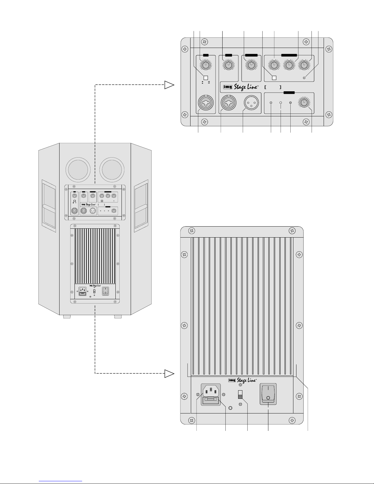
Bitte klappen Sie die Seite 3 heraus. Sie sehen
dann immer die beschriebenen Bedienelemente
und Anschlüsse.
1 Übersicht der Bedienelemente und
Anschlüsse
1 Umschalttaste für den Mikrofonkanal MIC, um
den Regelbereich für die mit dem Gain-Regler
(2) einstellbare Verstärkung an die angeschlossene Signalquelle anzupassen
Taste ausgerastet: Verstärkung bis 40dB
Taste gedrückt: Verstärkung bis 60dB
2 Gain-Regler zur Pegeleinstellung für den Mikro-
fonkanal
3 Gain-Regler zur Pegeleinstellung für den Line-
Eingangskanal
4 Regler zum Einstellen der Grenzfrequenz des
Low-Cut-Filters: Regelbereich 20Hz – 120 Hz;
unerwünschte Signalanteile unterhalb der eingestellten Frequenz (z. B. Trittschall, Brummen)
werden unterdrückt
5 Umschalttaste zum Ein-/Ausschalten des Equali-
zers: bei gedrückter Taste ist die Klangregelung
eingeschaltet und die LED EQ ON (9) leuchtet
6 Klangregler für die Bässe: ±12dB/50Hz
7 Klangregler für die Mitten: ±12dB/1kHz
8 Klangregler für die Höhen: ±12dB/10kHz
9 LED EQ ON: leuchtet, wenn der Equalizer einge-
schaltet ist [Taste EQ ON/OFF (5) gedrückt]
10 symmetrische Eingangbuchse MIC IN (kombi-
nierte XLR-/6,3-mm-Klinkenbuchse) für den Anschluss eines Mikrofons bzw. einer anderen Signalquelle mit niedrigem Ausgangspegel (z.B.
Empfänger eines Funkmikrofon-Systems)
11 symmetrische Eingangsbuchse LINE IN (kombi-
nierte XLR-/6,3-mm-Klinkenbuchse) für den Anschluss eines Gerätes mit Line-Pegel
12 symmetrischer XLR-Durchschleifausgang, paral-
lel geschaltet zum Eingang LINE IN (11)
13 Betriebsanzeige POWER
14 Übersteuerungsanzeige CLIP: leuchtet, wenn die
Endstufe übersteuert wird [den Regler LEVEL
(16) und/oder die Regler GAIN (2, 3) dann entsprechend zurückdrehen]
15 LED PROTECT: leuchtet, wenn die Schutzschal-
tung anspricht
1. kurz nach dem Ein- und Ausschalten
2. bei Überhitzung oder einem Defekt (z.B.
einem Kurzschluss am Endstufenausgang)
16 Pegelregler LEVEL für die Gesamtlautstärke
17 Netzbuchse zum Anschluss an eine Steckdose
(230V~/50 Hz) über das beiliegende Netzkabel
18 Sicherungshalter; eine durchgebrannte Netzsi-
cherung nur durch eine gleichen Typs ersetzen
19 Ground-Lift-Schalter
Position GND Signalmasse und Schutzleiter
sind elektrisch verbunden
Position LIFT Signalmasse und Schutzleiter
sind getrennt
20 Ein-/Ausschalter POWER
21 Kühlrippen
2 Hinweise für den sicheren Gebrauch
Dieses Gerät entspricht der Richtlinie für elektromagnetische Verträglichkeit 89/ 336/ EWG und der
Niederspannungsrichtlinie 73/23/EWG.
Beachten Sie auch unbedingt die folgenden Punkte:
●
Das Gerät ist nur zur Verwendung in Innenräumen
geeignet. Schützen Sie es vor Tropf- und Spritzwasser, hoher Luftfeuchtigkeit und Hitze (zulässiger Einsatztemperaturbereich 0– 40 °C).
●
Stellen Sie keine mit Flüssigkeit gefüllten Gefäße,
z.B. Trinkgläser, auf das Gerät.
●
Die in der Lautsprecherbox entstehende Wärme
wird durch die Kühlrippen (21) abgegeben. Decken Sie diese deshalb nicht ab. Stellen Sie die
Box nie direkt an eine Wand; halten Sie einen entsprechenden Abstand ein.
●
Nehmen Sie das Gerät nicht in Betrieb bzw. ziehen Sie sofort den Netzstecker aus der Steckdose:
1. wenn sichtbare Schäden am Gerät oder an der
Netzanschlussleitung vorhanden sind,
2. wenn nach einem Sturz oder Ähnlichem der
Verdacht auf einen Defekt besteht,
3. wenn Funktionsstörungen auftreten.
Lassen Sie das Gerät in jedem Fall in einer Fachwerkstatt reparieren.
●
Ziehen Sie den Netzstecker nie am Kabel aus der
Steckdose, fassen Sie immer am Stecker an.
●
Verwenden Sie für die Reinigung nur ein trockenes, weiches Tuch, niemals Wasser oder Chemikalien.
Achtung! Das Gerät wird mit lebensgefährlicher
Netzspannung (230 V~) versorgt. Nehmen Sie deshalb niemals selbst Eingriffe im Gerät vor. Durch unsachgemäßes Vorgehen besteht die Gefahr
eines elektrischen Schlages. Außerdem
erlischt beim Öffnen des Gerätes jeglicher Garantieanspruch.
Please unfold page 3. Then you can always see
the operating elements and connections described.
1 Elements and Connections
1 Selector switch for the microphone channel MIC
to match the control range for the amplification
adjustable with the gain control (2) to the
connected signal source
button released: amplification up to 40dB
button pressed: amplification up to 60dB
2 Gain control for level adjustment for the micro-
phone channel
3 Gain control for level adjustment for the line input
channel
4 Control for adjusting the limit frequency of the
low cut filter: control range 20Hz – 120 Hz;
unwanted signal parts below the adjusted frequency (e. g. rumble noise, humming) are suppressed
5 Selector switch for switching on/off the equalizer:
with the button pressed, the equalizer is switched
on and the LED EQ ON (9) lights up
6 Equalizer for the bass range: ±12dB/50 Hz
7 Equalizer for the midrange: ±12dB/1kHz
8 Equalizer for the high range: ±12dB/10 kHz
9 LED EQ ON: lights up if the equalizer is switched
on [button EQ ON/OFF (5) pressed]
10 Balanced input jack MIC IN (combined XLR/
6.3mm jack) for the connection of a microphone
or another signal source with low output level
(e.g. receiver of a wireless microphone system)
11 Balanced input jack LINE IN (combined XLR/
6.3mm jack) for the connection of a unit with line
level
12 Balanced XLR feed-through output, connected in
parallel to the input LINE IN (11)
13 POWER LED
14 Overload indication CLIP: lights up if the power
amplifier is overloaded [in this case turn back the
control LEVEL (16) and/ or the controls GAIN
(2, 3) correspondingly]
15 LED PROTECT: lights up if the protective circuit
responds
1. shortly after switching on and off
2. in case of overheating or defect (e.g. a short
circuit at the output of the power amplifier)
16 LEVEL control for the total volume
17 Mains jack for connection to a mains socket
(230V~/50 Hz) via the supplied mains cable
18 Fuse holder; only replace a blown mains fuse by
one of the same type
19 Ground lift switch
position GND signal ground and earthed con-
ductor are electrically connected
position LIFT signal ground and earthed con-
ductor are separated
20 POWER switch
21 Cooling fins
2 Safety Notes
This unit corresponds to the directive 89/ 336 /EEC
for electromagnetic compatibility and to the low voltage directive 73/23/EEC.
It is essential to observe the following items:
●
The unit is suitable for indoor use only. Protect it
against dripping water and splash water, high air
humidity, and heat (admissible ambient temperature range 0– 40 °C).
●
Do not place any vessels filled with liquid, e. g.
drinking glasses, on the unit.
●
The heat being generated within the speaker cabinet is dissipated via the cooling fins (21). Therefore, do not cover them. Never place the cabinet
directly to a wall; keep a corresponding distance.
●
Do not set the unit into operation, and immediately
disconnect the mains plug from the mains socket if
1. there is visible damage to the unit or to the
mains cable,
2. a defect might have occurred after a drop or
similar accident,
3. there are malfunctions.
The unit must in any case be repaired by skilled
personnel.
●
Never pull the mains cable to disconnect the mains
plug from the mains socket, always seize the plug.
●
For cleaning only use a dry, soft cloth, by no
means chemicals or water.
●
If the unit is used for purposes other than originally
intended, if it is not connected or operated correctly, or not repaired in an expert way, there is no liability for resulting damage to persons or material
and no guarantee for the unit can be taken over.
Attention!The unit is supplied with hazardous
mains voltage (230 V~). Leave servicing to skilled personnel only. Inexpert
handling may cause an electric shock
hazard. Furthermore, any guarantee
claim will expire if the unit has been
opened.
4
GB
D
A
CH

●
Wird das Gerät zweckentfremdet, nicht richtig
angeschlossen, falsch bedient oder nicht fachgerecht repariert, kann keine Haftung für daraus
resultierende Sach- oder Personenschäden und
keine Garantie für das Gerät übernommen werden.
●
Soll das Gerät endgültig aus dem Betrieb genommen werden, übergeben Sie es zur umweltgerechten Entsorgung einem örtlichen Recyclingbetrieb.
3 Einsatzmöglichkeiten
Die Aktivbox PAK-415 mit einem 38-cm-Tieftöner
(15") und einem Hornhochtöner ist optimal für PAund DJ-Anwendungen geeignet (z. B. für Live-Auftritte kleiner Bands, Tanzveranstaltungen etc.).
Die Aktivbox ist mit einer 300-W-Endstufe ausgestattet und verfügt über ein regelbares Low-Cut-Filter, eine 3fach-Klangregelung mit Bypass-Schalter
und über getrennt regelbare, symmetrische Mikrofon- und Line-Eingänge. Über den Durchschleifausgang kann eine weitere Aktivbox angeschlossen
werden.
4 Aufstellung
Die Box kann frei auf den Boden aufgestellt oder
über die Stativhülse auf der Geräteunterseite auf ein
PA-Boxen-Stativ (z. B. PAST-Serie aus dem Sortiment von MONACOR) gesteckt werden.
5 Geräte anschließen
1) Die Audiogeräte entweder über einen XLR- oder
einen 6,3-mm-Klinkenstecker an die jeweiligen
symmetrischen Eingangsbuchsen anschließen:
Buchse MIC IN (10)
für den Anschluss eines Mikrofons bzw. Empfängers eines Funkmikrofons
Buchse LINE IN (11)
für den Anschluss eines Geräts mit Line-Ausgang (z.B. Instrument, Mischpult)
2) Am symmetrischen XLR-Ausgang PARALLEL
OUT (12) steht das durchgeschleifte Line-Eingangssignal der Buchse LINE IN zur Verfügung.
Hier kann z. B. der Line-Eingang einer weiteren
Aktivbox angeschlossen werden.
3) Zuletzt das beiliegende Netzkabel an die Netzbuchse (17) anschließen und mit einer Steckdose (230V~/50 Hz) verbinden.
6 Bedienung
Vor dem Einschalten sollte der Regler LEVEL(16) in
die Position „0“ gestellt werden, um eventuelle Einschaltgeräusche zu vermeiden.
1) Die angeschlossenen Signalquellen einschalten.
2) Die Aktivbox mit dem Ein-/Ausschalter POWER
(20) einschalten. Als Betriebsanzeige leuchtet
die grüne LED POWER (13).
3) Den Regler LEVEL(16) für die Gesamtlautstärke
so weit aufdrehen, dass das Mischungsverhältnis
der Eingangskänale optimal eingestellt werden
kann. Mit den Pegelreglern GAIN (2, 3) die Eingangskanäle mischen. Wird ein Kanal nicht benutzt, seinen Pegelregler auf „0“ stellen.
Ist der Ausgangspegel der Signalquelle am
Mikrofonkanal MIC zu niedrig, kann durch Drücken der Umschalttaste (1) der Regelbereich für
die Verstärkung erhöht werden.
4) Anschließend mit dem Regler LEVELdie endgültige gewünschte Lautstärke einstellen. Bei Übersteuerung der Endstufe leuchtet die gelbe LED
CLIP (14) – dann den Regler LEVEL und /oder
die Regler GAIN entsprechend zurückdrehen.
5) Mit dem Equalizer lässt sich das Klangbild einstellen. Dazu die Taste EQ ON/OFF (5) drücken:
die grüne LED EQ ON (9) leuchtet und die Klangregelung ist eingeschaltet. Durch Ausrasten der
Taste kann die Klangregelung bei Bedarf überbrückt (ausgeschaltet) werden.
Mit den Klangreglern (6, 7, 8) das gewünschte
Klangbild einstellen: Die Tiefen (Regler LOW),
Mitten (Regler MID) und Höhen (Regler HIGH)
lassen sich bis ±12 dB regeln. In der Mittelstellung der Regler findet keine Klangbeeinflussung
statt.
6) Mit dem Regler FREQUENCY (4) lässt sich die
untere Grenzfrequenz für das Low-Cut-Filter
(Hochpass) im Bereich 20Hz –120Hz einstellen.
Tieffrequente Störungen unterhalb der eingestellten Grenzfrequenz (z.B. Trittschall) werden unterdrückt. Je weiter der Regler im Uhrzeigersinn aufgedreht wird, desto höher liegt die Grenzfrequenz.
7) Ist durch die V erkabelung der Geräte eine Masseschleife entstanden, tritt ein Brummen auf (z. B.
bei leisen Musikpassagen). Diese Masseschleife
lässt sich mit dem Ground-Lift-Schalter (19) unterbrechen. Dazu den Schalter in Position „LIFT“
schieben. Die Signalmasse und der Schutzleiter
sind dann getrennt.
Andererseits ist die Aktivbox nicht gegen elektrische Störfelder abgeschirmt, wenn die Signalmasse nicht mit dem Schutzleiter verbunden ist.
Im Zweifelsfall den Schalter wechselweise schalten, um die optimale Einstellung zu finden.
7 Schutzschaltung
Bei aktivierter Schutzschaltung leuchtet die rote LED
PROTECT (15) und die Lautstärke wird reduziert:
1. kurz nach dem Einschalten und Ausschalten
2. bei Überhitzung der Endstufe bzw. einem Defekt
(Kurzschluss oder Gleichspannungsüberlagerung
am Endstufenausgang)
Leuchtet die LED PROTECT während des Betriebs
auf oder erlischt sie nicht nach dem Einschalten, das
Gerät ausschalten und die Fehlerursache beheben.
●
If the unit is to be put out of operation definitively,
take it to a local recycling plant for disposal which
is not harmful to the environment.
●
Important for U.K. Customers!
The wires in this mains lead are coloured in accordance with the following code:
green/yellow = earth
blue = neutral
brown = live
As the colours of the wires in the mains lead of this
appliance may not correspond with the coloured
markings identifying the terminals in your plug,
proceed as follows:
1. The wire which is coloured green and yellow
must be connected to the terminal in the plug
which is marked with the letter E or by the earth
symbol , or coloured green or green and yel-
low.
2. The wire which is coloured blue must be connected to the terminal which is marked with the
letter N or coloured black.
3. The wire which is coloured brown must be connected to the terminal which is marked with the
letter L or coloured red.
Warning
-
This appliance must be earthed.
3 Applications
The active speaker system PAK-415 with a 38 cm
(15") subwoofer and a horn speaker is suited in an
optimum way for PA and DJ applications (e. g. for
live performances of small bands, dancing events
etc.)
The active speaker is eqipped with a 300W
power amplifier and has a low cut filter to be controlled, a 3-way equalizer with bypass switch and
balanced microphone and line inputs which can be
controlled separately. Another active speaker system can be connected via the feed-through output.
4 Setting-up
The speaker system can be placed on the floor as
desired or be installed on a PAspeaker system stand
(e.g. PAST series of the MONACOR product range)
via the stand sleeve on the lower side of the unit.
5 Connecting the Units
1) Connect the audio units either via an XLR plug or
a 6.3 mm plug to the respective balanced input
jacks:
jack MIC IN (10)
for the connection of a microphone or receiver
of a wireless microphone
jack LINE IN (11)
for the connection of a unit with line output
(e.g. instrument, mixer)
2) The fed-through line input signal of jack LINE IN is
available at the balanced XLR output PARALLEL
OUT (12). To this jack, e.g. the line input of another active speaker system may be connected.
3) Finally connect the supplied mains cable to the
mains jack (17) and to a mains socket (230 V~ /
50Hz).
6 Operation
Prior to switching-on, the control LEVEL (16) should
be set to position “0” to prevent possible switchingon noise.
1) Switch on the connected signal sources.
2) Switch on the active speaker system with the
POWER switch (20). The green LED POWER
(13) lights up.
3) Turn up the control LEVEL (16) for the total
volume so that the mixing ratio of the input channels can be adjusted in an optimum way. Mix the
input channels with the level controls GAIN (2, 3).
If a channel is not used, set its level control to “0”.
If the output level of the signal source at the
microphone channel MIC is too low, press the
selector switch (1) to increase the control range
for the amplification.
4) Then adjust the final desired volume with the
control LEVEL. If the power amplifier is overloaded, the yellow LED CLIP (14) lights up – then turn
back the control LEVELand/or the controls GAIN
correspondingly.
5) It is possible to adjust the sound with the equalizer. For this purpose press the button EQ ON/
OFF (5): the green LED EQ ON (9) lights up and
the equalizer is switched on. Release the button
to bridge (switch off) the equalizer, if required.
Adjust the desired sound with the equalizers
(6, 7, 8): the bass range (control LOW), the midrange (control MID), and the high range (control
HIGH) can be controlled up to ± 12dB. The sound
will not be influenced in the mid-position of the
controls.
6) With the control FREQUENCY (4) the lower limit
frequency for the low cut filter (high pass) can be
adjusted in the range of 20Hz to 120 Hz. Low-frequency interferences below the adjusted limit frequency (e.g. rumble sound) are suppressed. The
more the control is turned up clockwise, the higher the limit frequency.
7) If a ground loop has come into being by cabling of
the units, humming occurs (e. g. in case of lowvolume music passages). This ground loop can
be interrupted with the ground lift switch (19). For
this purpose slide the switch to position “LIFT”.
Then the signal ground and the earthed conductor are separated.
On the other hand the active speaker system
is not shielded against electric noise fields if the
signal ground is not connected to the earthed
conductor. In case of doubt set the switch alternately to find the optimum adjustment.
5
GB
D
A
CH
 Loading...