

IMG STAGE LINE ODP-1210RGBW Instruction Manual
ODP-1210RGBW Bestellnummer 38.3140
BEDIENUNGSANLEITUNG • INSTRUCTION MANUAL • MODE D’EMPLOI • ISTRUZIONI PER L’USO
ISTRUZIONI PER L’USO • MANUAL DE INSTRUCCIONES • INSTRUKCJA OBSŁUGI • VEILIGHEIDSVOORSCHRIFTEN
SIKKERHEDSOPLYSNINGER • SÄKERHETSFÖRESKRIFTER • TURVALLISUUDESTA
DMX-LED-SCHEINWERFER
DMX LED SPOTLIGHT
PROJECTEUR DMX À LEDS
PROIETTORE DMX A LED

2
wwwwww..iimmggssttaaggeelliinnee..ccoomm
Bevor Sie einschalten …
Wir wünschen Ihnen viel Spaß mit Ihrem neuen Gerät
von „img Stage Line“. Bitte lesen Sie diese Bedienungsanleitung vor dem Betrieb gründlich durch. Nur so lernen
Sie alle Funktionsmöglichkeiten kennen, vermeiden
Fehlbedienungen und schützen sich und Ihr Gerät vor
eventuellen Schäden durch unsachgemäßen Gebrauch.
Heben Sie die Anleitung für ein späteres Nachlesen auf.
Der deutsche Text beginnt auf der Seite 4.
Before switching on …
We wish you much pleasure with your new “img Stage
Line” unit. Please read these operating instructions carefully prior to operating the unit. Thus, you will get to know
all functions of the unit, operating errors will be prevented, and yourself and the unit will be protected
against any damage caused by improper use. Please
keep the oper ating instructions for later use.
The English text starts on page 10.
Avant toute installation …
Nous vous souhaitons beaucoup de plaisir à utiliser cet
appareil “img Stage Line”. Lisez ce mode dʼemploi entièrement avant toute utilisation. Uniquement ainsi, vous
pourrez apprendre lʼensemble des possibilités de fonctionnement de lʼappareil, éviter toute manipulation erronée
et vous protéger, ainsi que lʼappareil, de dommages éventuels engendrés par une utilisation inadaptée. Conservez la notice pour pouvoir vous y reporter ultérieurement.
La version française se trouve page 16.
Prima di accendere …
Vi auguriamo buon divertimento con il vostro nuovo
apparecchio di “img Stage Line”. Leggete attentamente
le istruzioni prima di mettere in funzione lʼapparecchio.
Solo così potete conoscere tutte le funzionalità, evitare
comandi sbagliati e proteggere voi stessi e lʼapparecchio
da eventuali danni in seguito ad un uso improprio. Conservate le istruzioni per poterle consultare anche in
futuro.
Il testo italiano inizia a pagina 21.
D
A
CH
GB
Antes de la utilización …
Le deseamos una buena utilización para su nue vo aparato “img Stage Line”. Por favor, lea estas in s trucciones
de uso atentamente antes de ha cer funcionar el aparato.
De esta manera conocerá todas las funciones de la unidad, se pre vendrán errores de operación, usted y el apa rato estarán protegidos en contra de todo daño cau sado
por un uso inadecuado. Por favor, guarde las instrucciones para una futura utilización.
La versión española comienza en la página 26.
Voor u inschakelt …
Wij wensen u veel plezier met uw nieuwe apparaat van
“img Stage Line”. Lees de veiligheidsvoorschriften grondig door, alvorens het apparaat in gebruik te nemen. Zo
behoedt u zichzelf en het apparaat voor eventuele
schade door ondeskundig gebruik. Bewaar de handleiding voor latere raadpleging.
De veiligheidsvoorschriften vindt u op pagina 36.
Przed uruchomieniem …
Życzymy zadowolenia z nowego produktu “img Stage
Line”. Dzięki tej instrukcji obsługi będą państwo w stanie
poznać wszystkie funkcje tego urządzenia. Stosując się
do instrukcji unikną państwo błędów i ewentualnego
uszkodzenia urządzenia na skutek nieprawidłowego
użytkowania. Prosimy zachować instrukcję.
Tekst polski zaczyna się na stronie 31.
Før du tænder …
Tillykke med dit nye “img Stage Line” produkt. Læs sikkerhedsanvisningerne nøje før ibrugtagning, for at
beskytte Dem og enheden mod skader, der skyldes forkert brug. Gem venligst denne betjeningsvejledning til
senere brug.
Sikkerhedsanvisningerne findes på side 36.
Innan du slår på enheten …
Vi önskar dig mycket glädje med din nya “img Stage
Line” produkt. Läs igenom säkerhetsföre skrifterna innan
en heten tas i bruk för att undvika skador till följd av
felaktig hantering. Behåll instruktionerna för framtida
bruk.
Säkerhetsföreskrifterna återfinns på sidan 37.
Ennen kytkemistä …
Toivomme Sinulle paljon miellyttäviä hetkiä uuden “img
Stage Line” laitteen kanssa. Ennen laitteen käyttöä pyydämme Sinua huolellisesti tutustumaan turvallisuusohjeisiin. Näin vältyt vahingoilta, joita virheellinen laitteen
käyttö saattaa aiheuttaa. Ole hyvä ja säilytä käyttöohjeet
myöhempää tarvetta varten.
Turvallisuusohjeet löytyvät sivulta 37.
F
B
CH
I
E
NL
PL
DK
S
FIN
B
MENU UP DOWN ENTER
3
POWER OUTDMX OUT
POWER IN
DMX IN
MENU UP DOWN ENTER
Remove the mains plug before opening the unit. Leave replacing of the mains supply cord and mains
fuse to qualified service personnel. This product is not intended for use other than stated.
Vor ffnen des Ger tes Netzstecker ziehen. Netzleitung und Netzsicherung nur von
Fachpersonal wechseln lassen. Ger t nur f r den angegebenen Zweck verwenden.
Avant d ouvrir l appareil, retirez la fiche secteur d alimentation. Toute intervention sur le
c ble secteur et le fusible secteur doit tre effectu e uniquement par du personnel qualifi . nutiliser que dans
le domaine d application d termin . Staccare la spina di rete prima di aprire l apparecchio, e far cambiare
il cavo di rete ed il fusibile di rete solo da persona esperta. Usare l apparecchio solo per lo scopo indicato.
123
4 5 6 7 8 9 10 7
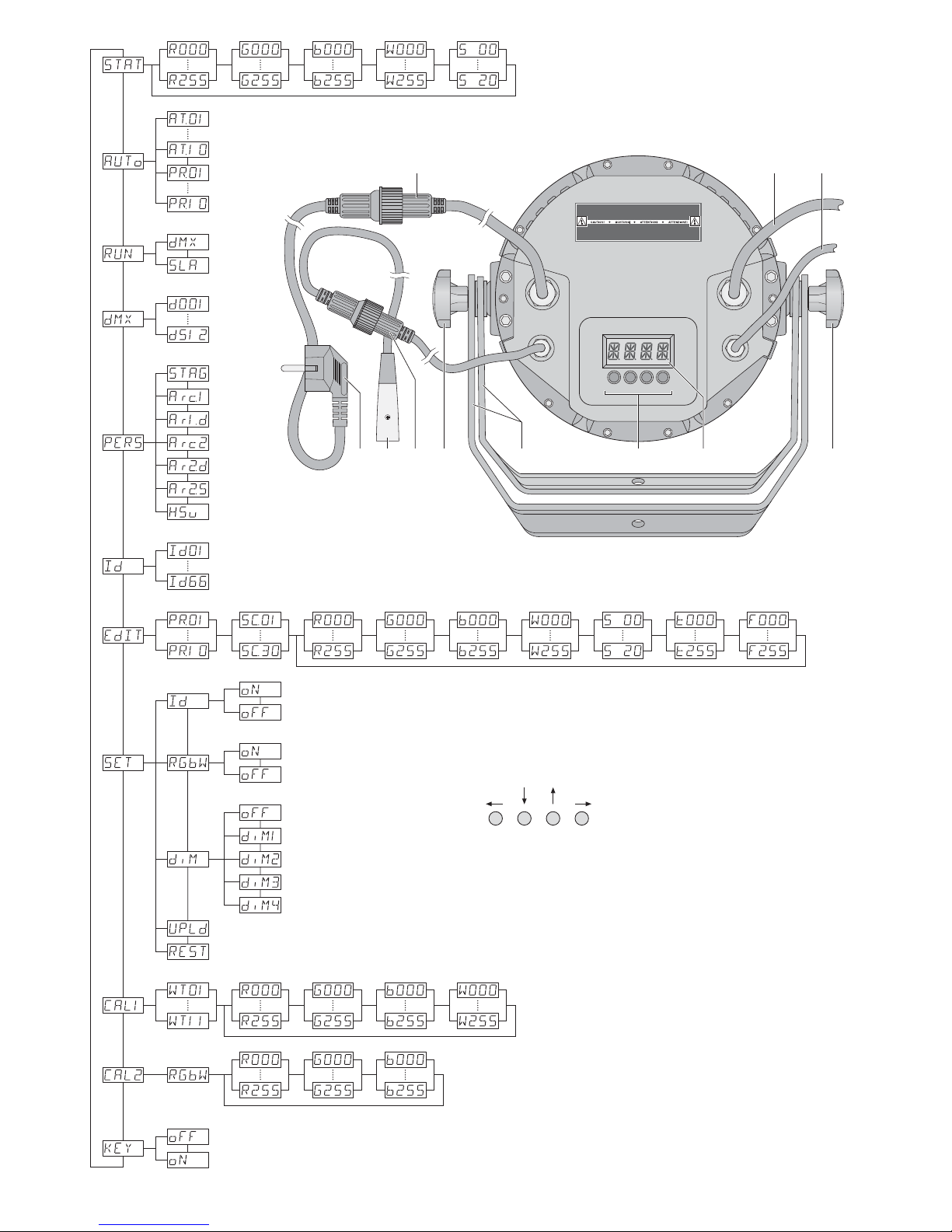
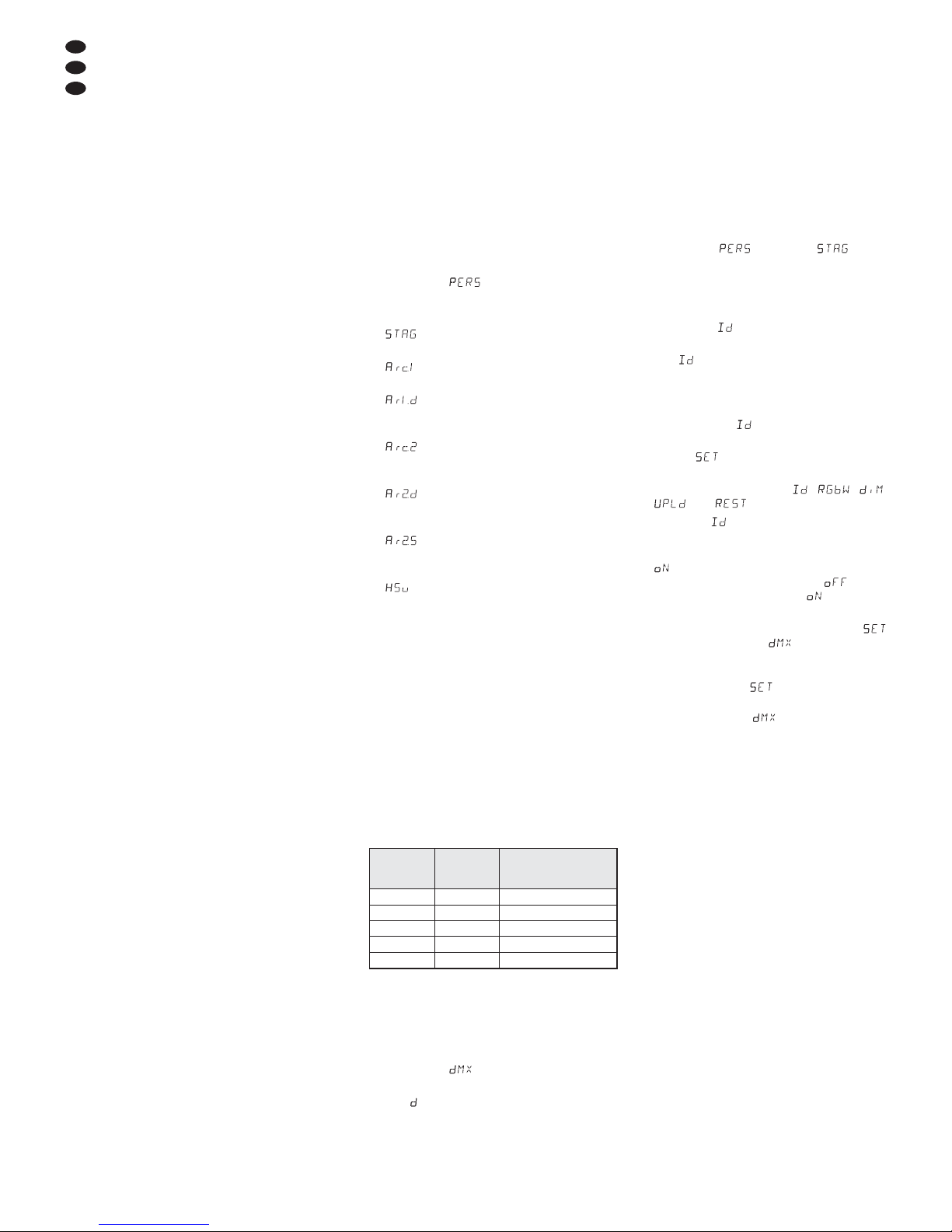
Menüstruktur
Menu structure
Structure du menu
Struttura del menù
Estructura del menú
Struktura menu
Showprogramme
show programmes
Farbstrahler / Stroboskop
colour radiator / stroboscope
programmierbare
Szenenfolgen
programmable
sequences of scenes
DMX-Startadresse
DMX start
address
11 DMX-Kanäle
11 DMX channels
3 DMX-Kanäle
3 DMX channels
4 DMX-Kanäle
4 DMX channels
4 DMX-Kanäle
4 DMX channels
5 DMX-Kanäle
5 DMX channels
6 DMX-Kanäle
6 DMX channels
3 DMX-Kanäle
3 DMX channels
Unteradresse ein
subaddress on
Unteradresse aus
subaddress off
Tastensperre aus
Key lock off
Tastensperre ein
Key lock on
Unteradresse
subaddress
11 Weißtöne oder
11 individuelle Farbtöne
11 shades of white or
11 individual shades of colour
Szenenfolgen
programmieren
programming
sequences of scenes
Master-Gerät*
master unit*
Slave-Gerät*
slave unit*
Weißabgleich
White balance
Weiß entspricht der Einstellung CAL2
white corresponds to the adjustment CAL2
Weiß = Rot, Grün + Blau auf max. Helligkeit
white = red, green + blue at max. brightness
Szenenfolgen auf die Nebengeräte kopieren
copying sequences of scenes to the slave units
Scheinwerfer auf die Werksprogrammierung zurücksetzen
resetting the spotlight to the factory settings
sofortige Reaktion der LEDs
immediate response of the LEDs
leicht träge Reaktion der LEDs
slightly slow response of the LEDs
träge Reaktion 2
slow response 2
träge Reaktion 3
slow response 3
maximal träge Reaktion
response as slow as possible
oberste Menüebene
highest menu level
* beim Master-Slave-Betrieb
* for master / slave mode
4
D
A
CH
Auf der ausklappbaren Seite 3 finden Sie
alle beschriebenen Bedienelemente und An schlüsse.
1 Übersicht der Bedienelemente
und Anschlüsse
1 Stecker des Kabels POWER IN für die Strom-
versorgung (230 V~ / 50 Hz):
Entweder über das Kabel mit dem Netzstecker (4) an eine Steckdose anschließen oder
an die Kupplung des Kabels POWER OUT
(2) eines weiteren ODP-1210RGBW
2 Anschlusskabel POWER OUT für die Strom-
versorgung eines weiteren ODP-1210RGBW
3 Anschlusskabel DMX OUT: DMX-Signalaus-
gang zum Anschluss an den DMX-Signaleingang eines weiteren ODP-1210RGBW
4 Netzstecker zum Anschluss an eine Steck-
dose (230 V~ / 50 Hz)
5 XLR-Stecker des DMX-Signaleingangs
Pin 1 = Masse, Pin 2 = DMX
-
, Pin 3 = DMX+
6 Stecker des Kabels DMX IN für den DMX-
Signaleingang:
Entweder über das Kabel mit dem XLR-Stecker (5) an ein Lichtsteuergerät anschließen
oder an den DMX-Signalausgang eines weiteren DMX-gesteuerten Gerätes
7 Feststellschrauben (2 ×) für die Montage- /
Aufstellbügel
8 Montage- /Aufstellbügel
9 Tasten zur Auswahl des Betriebsmodus und
zum Ändern von Einstellungen, siehe Abb. 2
10 Display
2 Hinweise für den
sicheren Gebrauch
Das Gerät entspricht allen relevanten Richtlinien
der EU und ist deshalb mit gekennzeichnet.
Beachten Sie unbedingt die folgenden Punkte:
G
Nehmen Sie das Gerät nicht in Betrieb und
ziehen Sie sofort den Netzstecker aus der
Steckdose,
1. wenn sichtbare Schäden am Gerät oder am
Netzkabel vorhanden sind,
2. wenn nach einem Sturz oder Ähnlichem der
Verdacht auf einen Defekt besteht,
3. wenn Funktionsstörungen auftreten.
Geben Sie das Gerät in jedem Fall zur Reparatur in eine Fachwerkstatt.
G
Ein beschädigtes Netzkabel darf nur durch
eine Fachwerkstatt ersetzt werden.
G
Ziehen Sie den Netzstecker nie am Kabel aus
der Steckdose, fassen Sie immer am Stecker
an.
G
Verwenden Sie zum Säubern des Scheinwerfergehäuses und der Schutzscheibe vor den
LEDs nur ein mildes Reinigungsmittel.
G
Wird das Gerät zweckentfremdet, nicht sicher
montiert, falsch bedient oder nicht fachgerecht repariert, kann keine Haftung für daraus
resultierende Sach- oder Personenschäden
und keine Garantie für das Gerät übernommen werden.
3 Einsatzmöglichkeiten
Dieser LED-Scheinwerfer dient zur Effektbeleuchtung. Der Scheinwerfer besitzt ein wetterfestes Aluminiumgehäuse (IP 67) und lässt sich
deshalb auch im Außenbereich einsetzen. Als
Lichtquelle werden 12 extrem helle LEDs verwendet. Der Scheinwerfer ist für die Steuerung
über ein DMX-Lichtsteuergerät ausgelegt (wahlweise 11, 6, 5, 4 oder 3 DMX-Steuerkanäle). Er
kann aber auch eigenständig ohne Steuergerät
betrieben werden.
Als Besonderheit bietet der ODP-1210RGBW
beim DMX-Betrieb die Verwendung von 66
Unteradressen. Dadurch lassen sich über eine
einzige DMX-Startadresse bis zu 66 Scheinwerfer (-gruppen) unabhängig voneinander steuern
und die maximal mögliche Anzahl DMX-gesteuerter Geräte wird erheblich erhöht. Die Anwahl
von Scheinwerfern mit einer Unteradresse
erfolgt über den DMX-Kanal 11.
4 Montage
G
Platzieren Sie das Gerät immer so, dass im
Betrieb eine ausreichende Luftzirkulation ge währleistet ist.
G
Der Abstand zum angestrahlten Objekt sollte
mindestens 50 cm betragen.
1. Den Scheinwerfer über die Montagebügel (8)
befestigen, z. B. mit einer stabilen Montage schraube oder einer Lichtstrahler-Halterung
(C-Haken) an einer Traverse.
Zum Ausrichten des Scheinwerfers die
zwei Feststellschrauben (7) an den Montagebügeln lösen. Die gewünschte Neigung des
Scheinwerfers einstellen und die Schrauben
wieder fest anziehen.
2. Alternativ lässt sich der Scheinwerfer auch
frei aufstellen: Die Montagebügel so unter
dem Scheinwerfer spreizen, dass sie als
Ständer dienen. Die Feststellschrauben da nach festdrehen.
5 Inbetriebnahme
Den Stecker (1) der Leitung POWER IN in die
Kupplung der beiliegenden Leitung mit dem
Netzstecker (4) stecken und die Steckverbindung mit der Überwurfmutter zusammenschrauben. Den Netzstecker in eine Steckdose
(230 V~/ 50Hz) stecken. Der Scheinwerfer ist
damit eingeschaltet. Das Display (10) zeigt für
einige Sekunden die letzte Menüeinstellung an
(Abb. 2) und erlischt dann.
VORSICHT! Ist kein weiterer Scheinwerfer an
den Kabeln POWER OUT (2) und DMX OUT (3)
angeschlossen, unbedingt die beiliegenden
Schutzkappen auf die Kupplungen schrauben.
Das Kabel POWER OUT führt Netzspannung.
5.1 Anschluss mehrerer Scheinwerfer
Werden mehrere ODP-1210RGBW eingesetzt,
können die Scheinwerfer zur Stromversorgung
miteinander verbunden werden. Den ersten
Scheinwerfer vorerst noch nicht an eine Steckdose anschließen.
1) Den 1. Scheinwerfer über die Kupplung des
Kabels POWER OUT (2) mit dem Stecker (1)
des Kabels POWER IN des 2. Scheinwerfers
verbinden. Genauso den 2. Scheinwerfer mit
dem 3. verbinden usw., bis alle Geräte in
einer Kette angeschlossen sind.
Sollten die Netzverbindungskabel zwischen den Scheinwerfern zu kurz sein, passende Verlängerungskabel verwenden, z. B.
ODP-34AC (2 m) oder ODP-34AC / 10 (10 m).
2) Am letzten Scheinwerfer auf die Kupplung
des Kabels POWER OUT (2) die beiliegende
Schutzkappe schrauben. Das Kabel führt
Netzspannung.
3) Zuletzt den Netzstecker des ersten Scheinwerfers in eine Steckdose (230 V~ / 50 Hz) stecken.
6 Bedienung
Die Bedientasten MENU, UP, DOWN und
ENTER (9) dienen zum Auswählen des Be triebsmodus und verschiedener Funktionen. Die
Abb. 2 auf der Seite 3 zeigt, wie die Modi und
Funktionen über ein Menü angewählt werden.
Einige Sekunden nach dem Drücken einer
Taste erlischt das Display (10). Sobald eine
Taste betätigt wird, leuchtet es wieder.
Hinweis: Das Gerät verfügt über einen Überhitzungsschutz. Dadurch schaltet es sich bei zu hoher Temperatur ab und nach dem Abkühlen automatisch wieder ein.
6.1 Eigenständiger Betrieb
Für den eigenständigen Betrieb den Scheinwerfer mit seinen Bedientasten (9) auf den ge wünschten Modus einstellen.
6.1.1 Farbstrahler und Stroboskop
In diesem Modus strahlt der Scheinwerfer konstant in einer einstellbaren Farbe. Zusätzlich
lässt sich die Stroboskop-Funktion einschalten.
1) Die Taste MENU so oft drücken, bis die
oberste Menüebene erreicht ist (in der Abb. 2
ganz links).
2) Die Taste UP oder DOWN so oft drücken, bis
das Display anzeigt.
3) Die Taste ENTER drücken. Das Display zeigt
jetzt , , , oder und eine Zahl.
= Helligkeit Rot (0 – 255)
= Helligkeit Grün (0 – 255)
= Helligkeit Blau (0 – 255)
= Helligkeit Weiß (0 – 255)
= Blitzfrequenz (0 – 20 Hz) des Stroboskops
4) Mit der Taste ENTER die fünf Einstellfunktio-
nen nacheinander anwählen und mit der
Taste UP oder DOWN jeweils die Helligkeit
bzw. die Blitzfrequenz einstellen.
Tipp: Beim Einstellen der Helligkeit der Farben Rot,
Grün und Blau ändert sich nicht nur deren Helligkeit,
sondern bei einer Farbmischung auch der Farbton.
Darum zuerst die Farbe, die dominieren soll, auf die
gewünschte Helligkeit einstellen und danach die
anderen beiden Farben dazumischen. Soll die Farbmischung Weiß ergeben, zuerst die Helligkeit der
Farbe Grün einstellen, weil diese dem Auge am
hellsten erscheint. Dann mit Rot zu Gelb mischen
und zuletzt mit Blau zu Weiß mischen.
WARNUNG Blicken Sie nicht für längere Zeit
direkt in die Lichtquelle, das kann
zu Augenschäden führen.
Beachten Sie, dass sehr schnelle
Lichtwechsel bei fotosensiblen
Menschen und Epileptikern epileptische Anfälle auslösen können!
WARNUNG Der Gesamtstrom in den An -
schlusskabeln (1, 2) darf 10 A
nicht überscheiten, sonst kann
durch Überlastung ein Kabelbrand entstehen. Darum nur
maximal 19 Scheinwerfer miteinander verbinden.
WARNUNG Der Scheinwerfer muss fachge-
recht und sicher montiert werden.
Wird er an einer Stelle installiert,
unter der sich Personen aufhalten
können, muss er zusätzlich ge sichert werden (z. B. durch ein
Fangseil am Montagebügel; das
Fangseil so befestigen, dass der
Fallweg des Gerätes nicht mehr
als 20 cm betragen kann).
Soll das Gerät endgültig aus dem Be trieb genommen werden, übergeben
Sie es zur umweltgerechten Entsorgung
einem örtlichen Recyclingbetrieb.
WARNUNG Das Gerät wird mit lebensgefähr -
licher Netzspannung versorgt. Nehmen Sie deshalb nie selbst Eingriffe
am Gerät vor. Durch unsachgemäßes Vorgehen besteht die Gefahr
eines elektrischen Schlages.
D
A
CH
5
6.1.2 Verschiedene Weißtöne
Speichern von 11 Farbtönen
In diesem Modus strahlt der Scheinwerfer weißes Licht ab. 11 verschiedene Weißtöne sind
gespeichert, die jedoch geändert werden können. Für jeden Weißton lässt sich die Helligkeit
für die Farben Rot, Grün, Blau und Weiß unterschiedlich einstellen, sodass dieser Modus auch
zum Speichern von 11 individuellen Farbtönen
genutzt werden kann.
1) Die Taste MENU so oft drücken, bis die
oberste Menüebene erreicht ist (in der Abb. 2
ganz links).
2) Die Taste UP oder DOWN so oft drücken, bis
das Display anzeigt.
3) Die Taste ENTER drücken. Das Display zeigt
jetzt einen der 11 Speicherplätze an ( …
) und die LEDs leuchten im entspre-
chenden Weißton.
4) Mit der Taste UP oder DOWN den ge -
wünschten Weißton wählen oder den Speicherplatz, dessen Einstellungen geändert
werden sollen.
5) Zum Ändern einer Einstellung nach dem
Anwählen des Speicherplatzes die Taste
ENTER drücken. Das Display zeigt jetzt , ,
oder und eine Zahl (0– 255).
= Helligkeit Rot
= Helligkeit Grün
= Helligkeit Blau
= Helligkeit Weiß
6) Mit der Taste ENTER die vier Farben nachei-
nander anwählen und jeweils die Helligkeit
mit der Taste UP oder DOWN einstellen.
7) Zum Aufrufen eines anderen Weißtones oder
zum Ändern der Einstellungen eines anderen
Speicherplatzes die Taste MENU drücken,
sodass wieder die Speicherplatznummer
angezeigt wird. Dann die Bedienschritte 4 – 6
wiederholen.
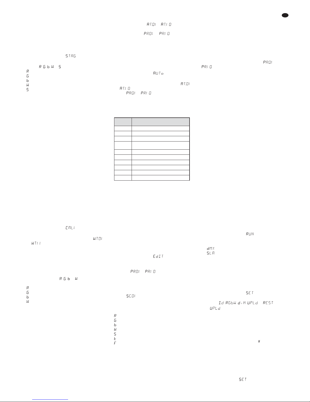
6.1.3 Showprogramme und Szenenfolgen
10 Showprogramme ( … ) sind im
Scheinwerfer gespeichert. Außerdem können 10
Szenenfolgen ( … ) mit bis zu 30
Szenen selbst programmiert werden (
Kap.
6.1.4). Die Showprogramme und Szenenfolgen
lassen sich wie folgt starten:
1) Die Taste MENU so oft drücken, bis die
oberste Menüebene erreicht ist (in der Abb. 2
ganz links).
2) Die Taste UP oder DOWN so oft drücken, bis
das Display anzeigt.
3) Die Taste ENTER drücken. Das Display zeigt
jetzt das zuletzt aufgerufene Showprogramm
( … ) oder die zuletzt aufgerufene
Szenenfolge ( … ) an.
4) Das Showprogramm oder die Szenenfolge
mit der Taste UP oder DOWN auswählen.
Die Showprogramme haben folgenden Ablauf:
Abb. 3 Showprogramme AT.01 – AT.10
6.1.4 Szenenfolgen programmieren
Es lassen sich 10 Szenenfolgen auf einfache
Weise programmieren. Eine Szenenfolge kann
aus max. 30 Szenen bestehen, die automatisch
nacheinander wechseln. Für jede Szene lässt
sich die Farbe zusammen mit der Helligkeit einstellen, die Stroboskop-Funktion mit variabler
Blitzfrequenz einschalten, die Szenendauer und
die Überblendzeit bestimmen.
1) Die Taste MENU so oft drücken, bis die
oberste Menüebene erreicht ist (in der Abb. 2
ganz links).
2) Die Taste UP oder DOWN so oft drücken, bis
das Display anzeigt.
3) Die Taste ENTER drücken. Das Display zeigt
die Nummer der zuletzt gewählten Szenenfolge an ( … ).
4) Die Nummer, unter der die Szenenfolge
gespeichert werden soll, mit der Taste UP
oder DOWN wählen und die Taste ENTER
drücken. Das Display zeigt die Nummer der
ersten Szene an ( ).
5) Durch weiteres Drücken der Taste ENTER
werden nacheinander folgende Einstellfunktionen aufgerufen:
= Helligkeit Rot
= Helligkeit Grün
= Helligkeit Blau
= Helligkeit Weiß
= Blitzfrequenz des Stroboskops
= Szenendauer (time), 100 = 60 Sek.
= Überblendzeit (fade)
Mit der Taste UP oder DOWN jeweils den
gewünschten Wert einstellen.
Hinweise
1. Die Zeitdauer einer Szene muss mindestens auf
den Wert 001 eingestellt werden, sonst lässt sich
die darauffolgende Szene nicht programmieren.
2. Soll von einer Szene auf die nächste Szene über-
geblendet werden, muss für beide Szenen eine
Überblendzeit eingestellt werden.
6) Nachdem die erste Szene eingestellt ist, die
Taste MENU drücken. Das Display zeigt wieder die Szenennummer an. Mit der Taste UP
die zweite Szene anwählen, die Taste
ENTER drücken, die Szene einstellen und
den Vorgang für alle anschließenden Szenen
wiederholen.
7) Nachdem die letzte Szene eingestellt ist, die
Szenenfolge speichern: Die Taste ENTER
5 Sekunden gedrückt halten. Nach dem Lösen
der Taste muss das Display die Nummer der
Szenenfolge anzeigen ( … ),
anderenfalls wurde die Taste ENTER nicht
lange genug gedrückt.
Hinweise
1. Eine Szenenfolge muss komplett programmiert wer-
den, bevor der Scheinwerfer von der Stromversorgung getrennt wird. Nach dem erneuten Einschalten
lässt sich eine Szenenfolge nicht mehr ändern; sie
kann nur neu programmiert werden. Zum Überschreiben einer Szenenfolge brauchen so die zuvor programmierten Szenen nicht erst gelöscht zu werden.
2. Werden die Szenenfolgen nicht mit den Be dientasten
(9) aufgerufen (Kap. 6.1.3), sondern über ein DMXLichtsteuergerät, bestimmt der DMX-Kanal 2 die Szenendauer und der Kanal 3 die Überblendzeit (Kap.
6.3.5). Der Kanal 2 muss dabei auf einen DMX-Wert
von mindestens 001 eingestellt sein, sonst bleibt der
Scheinwerfer dunkel.
6.2 Synchrone Steuerung mehrerer
Scheinwerfer (Master-Slave-Modus)
Es lassen sich mehrere ODP-1210RGBW
zusammenschließen. Das Hauptgerät (Master)
kann dann alle Nebengeräte (Slave) synchron
steuern.
1) Die Scheinwerfer jeweils über die Kupplung
des Kabels DMX OUT (3) und den Stecker
(6) des Kabels DMX IN miteinander zu einer
Kette verbinden. Siehe dazu Kapitel 6.3.1
„DMX-Anschluss“, jedoch ohne den Bedienschritt 1 zu beachten.
2) Für den Master-Slave-Modus ist der Schein-
werfer ab Werk als Nebengerät eingestellt.
So muss nur der Scheinwerfer, der die
Nebengeräte steuern soll, als Hauptgerät
eingestellt werden. Zum Ändern der Einstellung:
a) Die Taste MENU so oft drücken, bis die
oberste Menüebene erreicht ist (in der
Abb. 2 ganz links).
b) Die Taste UP oder DOWN so oft drücken,
bis das Display anzeigt.
c) Die Taste ENTER drücken und mit der
Taste UP oder DOWN wählen:
= Hauptgerät
= Nebengerät
3) Wurden am Hauptgerät Szenenfolgen pro-
grammiert (Kap. 6.1.4), können diese auf die
Nebengeräte kopiert werden:
a) Am Hauptgerät die Taste MENU so oft
drücken, bis die oberste Menüebene
erreicht ist (in der Abb. 2 ganz links).
b) Die Taste UP oder DOWN so oft drücken,
bis das Display anzeigt.
c) Die Taste ENTER drücken. Das Display
springt auf die Anzeige , , ,
oder um.
d) Wird nicht angezeigt, die Taste UP
oder DOWN entsprechend oft drücken.
e) Die Taste ENTER drücken. Das Display
erlischt. Dann folgende Tasten drücken:
UP, DOWN, UP, DOWN.
Das Drücken dieser Tasten wird jeweils
mit einem Stern ( ) im Display angezeigt.
f) Den Kopiervorgang mit der Taste ENTER
starten. Während des Kopiervorgangs
leuchten die Nebengeräte gelb, beim Auftreten eines Fehlers rot und nach einem
erfolgreichen Kopieren grün.
g) Zum Einschalten der gewünschten Be -
triebsart die Taste MENU so oft drücken,
bis das Display wieder anzeigt. Mit
der Taste UP oder DOWN die Betriebsart
auswählen und mit der Taste ENTER aktivieren.
Show -
programm
Ablauf
AT.01 Stroboskop: weißes Licht
AT.02 Ein- /Ausblenden: Rot, Grün, Blau, Weiß
AT.03 Farbwechsel: Rot, Grün, Blau, Weiß
AT.04
Farbwechsel: Rot, aus, Grün, aus,
Blau, aus, Weiß, aus
AT.05
Überblenden: Grün © Rot © Blau
AT.06 Ein- /Ausblenden: Violett, Gelb
AT.07 Ein- /Ausblenden: Violett, Gelb
AT.08 Ein- /Ausblenden: Violett
AT.09 Ein- /Ausblenden: Türkis, Violett
AT.10 Ein- /Ausblenden: Violett, Grün
D
A
CH
6
6.3 Betrieb mit einem DMX-Steuergerät
DMX ist die Abkürzung für Digital Multiplex und
bedeutet digitale Steuerung von mehreren DMXGeräten über eine gemeinsame Steuerleitung.
Zur Bedienung über ein DMX-Lichtsteuergerät
(z. B. DMX-1440 oder DMX-510USB von „img
Stage Line“) verfügt der Scheinwerfer über 11
DMX-Steuerkanäle. Er lässt sich je nach Bedarf
aber auch über nur 6, 5, 4 oder 3 Kanäle steuern. Die Funktionen der Kanäle und die DMXWerte sind im Kapitel 6.3.5 angegeben.
6.3.1 DMX-Anschluss
Für die DMX-Verbindung sind 3-polige XLR-An schlüsse mit folgender Kontaktbelegung vorhanden:
Pin 1 = Masse, Pin 2 = DMX-, Pin 3 = DMX+
Zum Anschluss sollten spezielle Kabel für die
DMX-Signalübertragung verwendet werden
(z. B. Kabel der CDMXN-Serie von „img Stage
Line“). Bei Leitungslängen ab 150 m wird grundsätzlich das Zwischen schalten eines DMX-Aufholverstärkers empfohlen (z. B. SR-103DMX
von „img Stage Line“).
1) Den Stecker (6) der Leitung DMX IN in die
Kupplung der beiliegenden Leitung mit dem
XLR-Stecker (5) stecken und die Steckverbindung mit der Überwurfmutter zusammenschrauben. Den XLR-Stecker über ein Verlängerungskabel an den DMX-Ausgang des
Lichtsteuergerätes anschließen oder, wenn
weitere DMX-gesteuerte Geräte verwendet
werden, an den DMX-Ausgang des letzten
DMX-gesteuerten Gerätes der DMX-Signalleitung.
2) Werden weitere Scheinwerfer ODP1210RGBW verwendet, den ersten Scheinwerfer über die Kupplung des Kabels DMX
OUT (3) mit dem Stecker (6) des Kabels DMX
IN des 2. Scheinwerfers verbinden. Genauso
den 2. Scheinwerfer mit dem 3. verbinden
usw., bis alle Geräte in einer Kette angeschlossen sind.
Sollten die DMX-Verbindungskabel zwischen den Scheinwerfern zu kurz sein, passende Verlängerungskabel verwenden, z. B.
ODP-34DMX (Länge 2 m) oder
ODP-34DMX / 10 (Länge 10 m).
3) Sollte während des Betriebs die DMX-Steuerung nicht einwandfrei funktionieren, den
DMX-Ausgang des letzten Gerätes der Kette
mit einem 120-Ω-Widerstand (> 0,3 W) ab schließen. Um den DMX-Ausgang eines
ODP-1210RGBW
abzuschließen, ist es am
einfachsten, ein Verlängerungskabel ODP34DMX aufzutrennen und den Widerstand
mit den Pins 2 und 3 des Steckers zu verbinden. Den Stecker mit dem Widerstand in die
Kupplung des Kabels DMX OUT stecken.
6.3.2 Anzahl der DMX-Kanäle einstellen
Um den ODP-1210RGBW mit einem Lichtsteuergerät bedienen zu können, müssen die DMXStartadres se (
Kap. 6.3.3) und die Anzahl der
DMX-Kanäle eingestellt werden. Die Anzahl der
DMX-Kanäle hängt von den benötigten Funktionen ab und eventuell auch von der Anzahl der
verfügbaren Steuerkanäle am Lichtsteuergerät.
Informieren Sie sich im Kapitel 6.3.5 über die
Funktionen, die jeweils im 3-, 4-, 5-, 6- und 11Kanal-Betrieb möglich sind und wählen Sie
danach die Anzahl der DMX-Kanäle aus:
1) Die Taste MENU so oft drücken, bis die
oberste Menüebene erreicht ist (in der Abb. 2
ganz links).
2) Die Taste UP oder DOWN so oft drücken, bis
das Display anzeigt.
3) Die Taste ENTER drücken. Das Display zeigt
die momentane Einstellung an:
11 Kanäle
(
Kap. 6.3.5, Abb. 11 + 12)
3 Kanäle
1 = Rot, 2 = Grün, 3 = Blau
4 Kanäle
1 = Dimmer, 2 = Rot,
3 = Grün, 4 = Blau
4 Kanäle
1 = Rot, 2 = Grün,
3 = Blau, 4 = Weiß
5 Kanäle
1 = Dimmer, 2 = Rot, 3 = Grün,
4 = Blau, 5 = Weiß
6 Kanäle
1 = Dimmer, 2 = Rot, 3 = Grün,
4 = Blau, 5 = Weiß, 6 = Stroboskop
3 Kanäle
1 = Farbe, 2 = Farbsättigung,
3 = Helligkeit
4) Die Einstellung mit der Taste UP oder DOWN
auswählen.
6.3.3 DMX-Startadresse einstellen
Um den Scheinwerfer mit einem Lichtsteuergerät
bedienen zu können, muss die DMX-Startadres se für den ersten DMX-Kanal eingestellt werden.
Ist z. B. am DMX-Steuergerät die Adresse 17
zum Steuern der Funktion des ersten DMXKanals vorgesehen, am ODP-1210RGBW die
Startadresse 17 einstellen. Die weiteren DMXKanäle des ODP-1210RGBW sind dann automatisch den folgenden Adressen zugeordnet. Nachfolgend ist ein Beispiel mit der Startadresse 17
aufgeführt:
Abb. 4 DMX-Adressenbelegung
bei Verwendung der Startadresse 17
1) Die Taste MENU so oft drücken, bis die
oberste Menüebene erreicht ist (in der Abb. 2
ganz links).
2) Die Taste UP oder DOWN so oft drücken, bis
das Display anzeigt.
3) Die Taste ENTER drücken. Das Display zeigt
jetzt und eine Zahl zwischen 1 und 512.
4) Die Startadresse mit der Taste UP oder
DOWN einstellen.
Hinweis: Im Display blinkt ein Punkt, wenn der Scheinwerfer DMX-Signale empfängt.
6.3.4 Unteradressen verwenden
Durch die Verwendung von Unteradressen lassen sich über eine einzige DMX-Startadresse
bis zu 66 Scheinwerfer (-gruppen) unabhängig
voneinander steuern. Die maximal mögliche
Anzahl DMX-gesteuerter Geräte wird dadurch
erheblich erhöht. Die Anwahl von Scheinwerfern
mit einer Unteradresse erfolgt über den DMXKanal 11 (Abb. 12). Alle Scheinwerfer mit einer
Unteradresse lassen sich auch synchron steuern, wenn der DMX-Kanal 11 auf einen DMXWert von kleiner als 10 eingestellt wird.
1) Den Scheinwerfer für die Steuerung über 11
DMX-Kanäle einstellen,
Kap. 6.3.2
(Menüpunkt , Einstellung ).
2) Die Taste MENU so oft drücken, bis die
oberste Menüebene erreicht ist (in der Abb. 2
ganz links).
3) Die Taste UP oder DOWN so oft drücken, bis
das Display anzeigt.
4) Die Taste ENTER drücken. Das Display zeigt
jetzt und eine Zahl zwischen 01 und 66.
5) Die Unteradresse mit der Taste UP oder
DOWN einstellen.
6) Die Taste MENU drücken, sodass das Display wieder nur anzeigt.
7) Die Taste UP zweimal drücken, sodass das
Display anzeigt.
8) Die Taste ENTER drücken. Das Display
springt auf die Anzeige , , ,
oder um.
9) Wird nicht angezeigt, die Taste UP oder
DOWN entsprechend oft drücken.
10) Die Taste ENTER drücken. Zeigt das Display
an, ist die Funktion für die Unteradressenselektion eingeschaltet, zeigt es an, mit
der Taste UP oder DOWN auf umschalten.
11) Damit der Scheinwerfer DMX-gesteuert werden kann, muss aus dem Menüzweig
auf den Menü-Punkt gesprungen werden:
a) Die Taste MENU so oft drücken, bis das
Display wieder anzeigt.
b) Die Taste UP oder DOWN so oft drücken,
bis das Display anzeigt.
c) Die Taste ENTER drücken. Das Display
zeigt kurz die DMX-Startadresse an. Werden jetzt DMX-Steuersignale empfangen,
blinkt ein Punkt im Display.
12) Um den Scheinwerfer bedienen zu können,
am Lichtsteuergerät den DMX-Kanal 11 auf
den DMX-Wert stellen, welcher der Unteradresse des Scheinwerfers entspricht
(
Kap. 6.3.5, Abb. 12).
Anzahl der
DMX-Kanäle
belegte
DMX-Adressen
nächstmögliche Startadresse
für das
nachfolgende DMX-Gerät
3 17 – 19 20
4 17 – 20 21
5 17 – 21 22
6 17 – 22 23
11 17 – 27 28
D
A
CH
7
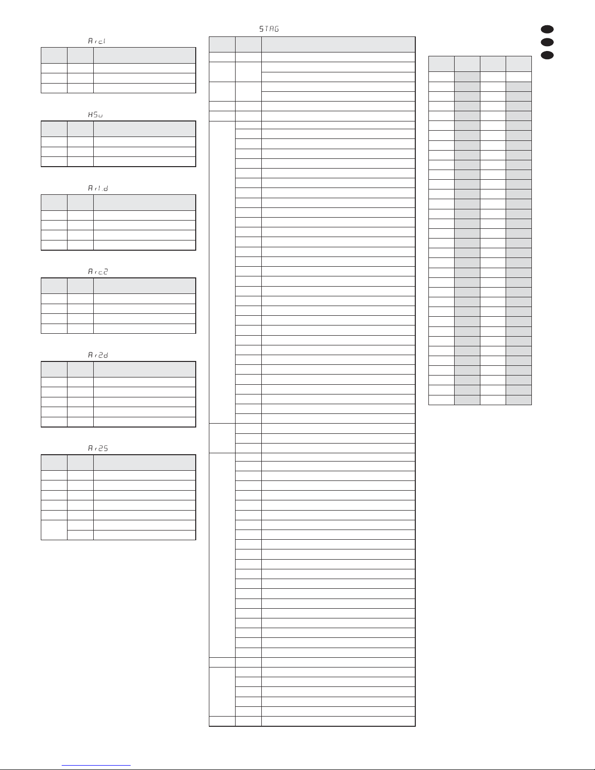
6.3.5 Funktionen der DMX-Kanäle
3-Kanal-Betrieb
Abb. 5
3-Kanal-Betrieb
Abb. 6
4-Kanal-Betrieb
Abb. 7
4-Kanal-Betrieb
Abb. 8
5-Kanal-Betrieb
Abb. 9
6-Kanal-Betrieb
Abb. 10
DMXKanal
DMX-
Wert
Funktion
1 000 – 255 Helligkeit Rot
2 000 – 255 Helligkeit Grün
3 000 – 255 Helligkeit Blau
DMXKanal
DMX-
Wert
Funktion
1 000 – 255 Farbe
2 000 – 255 Farbsättigung
3 000 – 255 Helligkeit
DMXKanal
DMX-
Wert
Funktion
1 000 – 255 Dimmer
2 000 – 255 Grundhelligkeit Rot
3 000 – 255 Grundhelligkeit Grün
4 000 – 255 Grundhelligkeit Blau
5 000 – 255 Grundhelligkeit Weiß
6
000 – 015 kein Stroboskop
016 – 255 Stroboskop 1 – 20 Hz
DMXKanal
DMX-
Wert
Funktion
1 000 – 255 Dimmer
2 000 – 255 Grundhelligkeit Rot
3 000 – 255 Grundhelligkeit Grün
4 000 – 255 Grundhelligkeit Blau
5 000 – 255 Grundhelligkeit Weiß
DMXKanal
DMX-
Wert
Funktion
1 000 – 255 Dimmer
2 000 – 255 Grundhelligkeit Rot
3 000 – 255 Grundhelligkeit Grün
4 000 – 255 Grundhelligkeit Blau
DMXKanal
DMX-
Wert
Funktion
1 000 – 255 Helligkeit Rot
2 000 – 255 Helligkeit Grün
3 000 – 255 Helligkeit Blau
4 000 – 255 Helligkeit Weiß
DMXKanal
DMX-
Wert
Funktion
1 000 – 255 Dimmer
2 000 – 255
Grundhelligkeit Rot
Szenendauer, wenn Kanal 8 = DMX-Wert > 109
3 000 – 255
Grundhelligkeit Grün
Überblendzeit, wenn Kanal 8 = DMX-Wert > 109
4 000 – 255 Grundhelligkeit Blau
5 000 – 255 Grundhelligkeit Weiß
6
000 – 010 keine Funktion
011 – 020
Rot ©Gelb
021 – 030
Gelb ©Grün
031 – 040
Grün ©Türkis
041 – 050
Türkis ©Blau
051 – 060
Blau ©Violett
061 – 070
Violett ©Rot
071 – 080
Rot ©Rosa
081 – 090
Rosa ©Rot
091 – 100
Grün ↔Rot
101 – 110
Blau ↔Rot
111 – 120
Blau ↔Grün
121 – 130
Blau ↔Gelb
131 – 140
Türkis ↔Rot
141 – 150
Grün ↔Violett
151 – 160
Blau ©Rot © Grün© Blau …
161 – 170
Türkis ©Gelb © Violett© Türkis …
171 – 180
Rot ©Grün © Blau© Weiß ©Rot …
181 – 190
Türkis ©Grün © Gelb© Rot © Violett© Blau © Türkis …
191 – 200 Weiß, max. Helligkeit
201 – 205
WT01 (Weißton 1, Kap. 6.1.2)
206 – 210 WT02
211 – 215 WT03
216 – 220 WT04
221 – 225 WT05
226 – 230 WT06
231 – 235 WT07
236 – 240 WT08
241 – 245 WT09
246 – 250 WT10
251 – 255 WT11
7
000 – 255 Geschwindigkeit, wenn Kanal 6 = DMX-Wert 011 – 190
000 – 015 kein Stroboskop
016 – 255 Stroboskop 1 – 20 Hz
8
000 – 009 keine Funktion
010 – 019
Showprogramm AT.01 (Abb. 3)
020 –029 Showprogramm AT.02
030 –039 Showprogramm AT.03
040 –049 Showprogramm AT.04
050 –059 Showprogramm AT.05
060 –069 Showprogramm AT.06
070 –079 Showprogramm AT.07
080 –089 Showprogramm AT.08
090 –099 Showprogramm AT.09
100 –109 Showprogramm AT.10
110 – 119
Szenenfolge PR.01 (Kap. 6.1.4)
120 – 129 Szenenfolge PR.02
130 – 139 Szenenfolge PR.03
140 – 149 Szenenfolge PR.04
150 – 159 Szenenfolge PR.05
160 – 169 Szenenfolge PR.06
170 – 179 Szenenfolge PR.07
180 – 189 Szenenfolge PR.08
190 – 199 Szenenfolge PR.09
200 – 255 Szenenfolge PR.10
9 000 – 255 Geschwindigkeit für AT.01 – AT.10
10
000 – 049 sofortige Reaktion der LEDs
050 –099
leicht träge Reaktion (Kap. 7.3)
100 – 149 träge Reaktion 2
150 – 199 träge Reaktion 3
200 – 255 maximal träge Reaktion
11 000– 255
Unteradressen, Abb. 12
DMX-
Wert
Unter-
adresse
DMX-
Wert
Unter-
adresse
000 – 009
alle
010 – 019 01 223 34
020 – 029
02 224 35
030 – 039
03 225 36
040 – 049
04 226 37
050 – 059
05 227 38
060 – 069
06 228 39
070 – 079
07 229 40
080 – 089
08 230 41
090 – 099
09 231 42
100 – 109
10 232 43
110 – 119
11 233 44
120 – 129
12 234 45
130 – 139
13 235 46
140 – 149
14 236 47
150 – 159
15 237 48
160 – 169
16 238 49
170 – 179
17 239 50
180 – 189
18 240 51
190 – 199
19 241 52
200 – 209
20 242 53
210
21 243 54
211
22 244 55
212
23 245 56
213
24 246 57
214
25 247 58
215
26 248 59
216
27 249 60
217
28 250 61
218
29 251 62
219
30 252 63
220
31 253 64
221
32 254 65
222
33 255 66
Anwahl von Scheinwerfern
mit einer Unteradresse
über den DMX-Kanal 11
11-Kanal-Betrieb
Abb. 11
Abb. 12
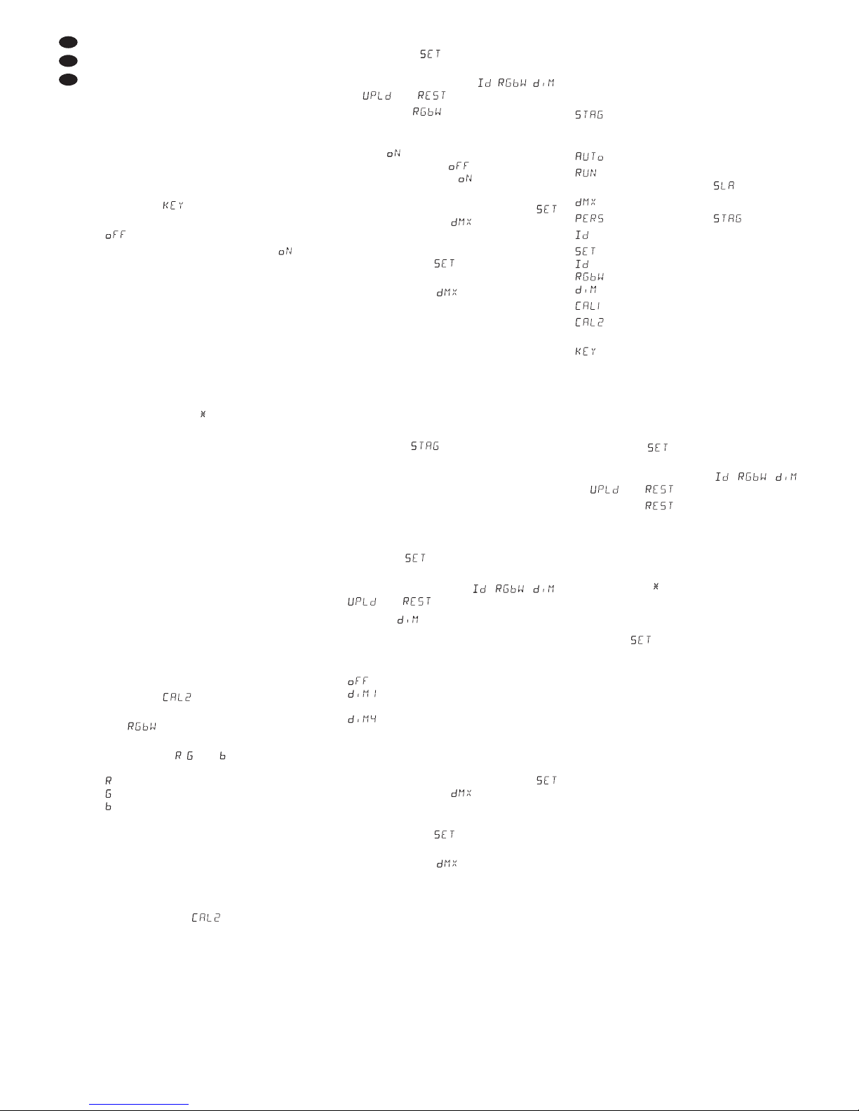
7 Zusätzliche Funktionen
7.1 Tastensperre
Zum Schutz gegen unbefugtes Verändern von
Einstellungen kann eine Tastensperre aktiviert
werden. Bei aktivierter Sperre können Einstellungen erst nach der Eingabe einer speziellen
Tastenfolge vorgenommen werden.
1) Die Taste MENU so oft drücken, bis die
oberste Menüebene erreicht ist (in der Abb. 2
ganz links).
2) Die Taste UP oder DOWN so oft drücken, bis
das Display anzeigt.
3) Die Taste ENTER drücken. Das Display zeigt
an (Tastensperre aus).
4) Mit der Taste UP oder DOWN auf um schalten. Sobald das Display erlischt, ist die
Tastensperre aktiviert.
5) Um jetzt Einstellungen vornehmen zu können:
a) Wenn das Display nicht leuchtet, zuerst
eine beliebige Taste drücken.
b) Die Taste ENTER drücken. Das Display
erlischt.
c) Dann folgende Tasten drücken:
UP, DOWN, UP, DOWN.
Das Drücken dieser Tasten wird jeweils
mit einem Stern ( ) im Display angezeigt.
d) Abschließend die Taste ENTER drücken.
Das Display zeigt den zuletzt gewählten
Menüpunkt an. Solange jetzt das Display
leuchtet, können Einstellungen vorgenommen werden. Erlischt es, ist die Tastensperre wieder aktiviert.
7.2 Weißabgleich
Der Scheinwerfer ist ab Werk so eingestellt,
dass bei maximaler Helligkeit der Farben Rot,
Grün und Blau ein bestimmter Weißton entsteht.
Dieser Weißton kann aber auch wärmer oder
kälter eingestellt werden, z. B. um Unterschiede
zu anderen Scheinwerfern auszugleichen, wenn
diese gemeinsam mit dem OPD-1210RGBW
gesteuert werden.
1) Die Taste MENU so oft drücken, bis die
oberste Menüebene erreicht ist (in der Abb. 2
ganz links).
2) Die Taste UP oder DOWN so oft drücken, bis
das Display anzeigt.
3) Die Taste ENTER drücken. Das Display zeigt
jetzt an.
4) Die Taste ENTER erneut drücken. Das Display zeigt jetzt , oder und eine Zahl zwischen 000 und 255.
= Helligkeit Rot
= Helligkeit Grün
= Helligkeit Blau
5) Mit der Taste ENTER die drei Einstellfunktionen nacheinander anwählen und mit der
Taste UP oder DOWN jeweils die Helligkeit
so einstellen, dass sich der gewünschte
Weißton ergibt.
6) Den eingestellten Weißton aktivieren:
a) Die Taste MENU so oft drücken, bis das
Display wieder anzeigt.
b) Die Taste DOWN zweimal drücken, sodass
das Display anzeigt.
c) Die Taste ENTER drücken. Das Display
springt auf die Anzeige , , ,
oder um.
d) Wird nicht angezeigt, die Taste UP
oder DOWN entsprechend oft drücken.
e) Die Taste ENTER drücken. Zeigt das Dis-
play an, ist der eingestellte Weißton
aktiviert, zeigt es an, mit der Taste
UP oder DOWN auf umschalten.
7) Damit der Scheinwerfer DMX-gesteuert werden kann, muss aus dem Menüzweig
auf den Menü-Punkt gesprungen werden:
a) Die Taste MENU so oft drücken, bis das
Display wieder anzeigt.
b) Die Taste UP oder DOWN so oft drücken,
bis das Display anzeigt.
c) Die Taste ENTER drücken. Das Display
zeigt kurz die DMX-Startadresse an. Wenn
jetzt DMX-Steuersignale empfangen werden, muss ein Punkt im Display blinken.
7.3 Träge Reaktion der LEDs
LEDs reagieren auf eine Änderung der Helligkeitseinstellung sofort. Um die träge Reaktion
herkömmlicher Leuchtmittel zu simulieren, lässt
sich die Reaktion in 4 Stufen einstellen. Bei dem
11-Kanalbetrieb erfolgt diese Einstellung
über den DMX-Kanal 10 (Kap. 6.3.5). Für den
3-, 4-, 5- und 6-Kanalbetrieb die Einstellung wie
folgt vornehmen:
1) Die Taste MENU so oft drücken, bis die
oberste Menüebene erreicht ist (in der Abb. 2
ganz links).
2) Die Taste UP oder DOWN so oft drücken, bis
das Display anzeigt.
3) Die Taste ENTER drücken. Das Display
springt auf die Anzeige , , ,
oder um.
4) Wird nicht angezeigt, die Taste UP oder
DOWN entsprechend oft drücken.
5) Die Taste ENTER drücken. Das Display zeigt
die momentane Einstellung an:
sofortige Reaktion
leicht träge Reaktion
…
maximal träge Reaktion
Die gewünschte Einstellung mit der Taste UP
oder DOWN wählen.
6) Damit der Scheinwerfer DMX-gesteuert werden kann, muss aus dem Menüzweig
auf den Menü-Punkt gesprungen werden:
a) Die Taste MENU so oft drücken, bis das
Display wieder anzeigt.
b) Die Taste UP oder DOWN so oft drücken,
bis das Display anzeigt.
c) Die Taste ENTER drücken. Das Display
zeigt kurz die DMX-Startadresse an. Werden jetzt DMX-Steuersignale empfangen,
blinkt ein Punkt im Display.
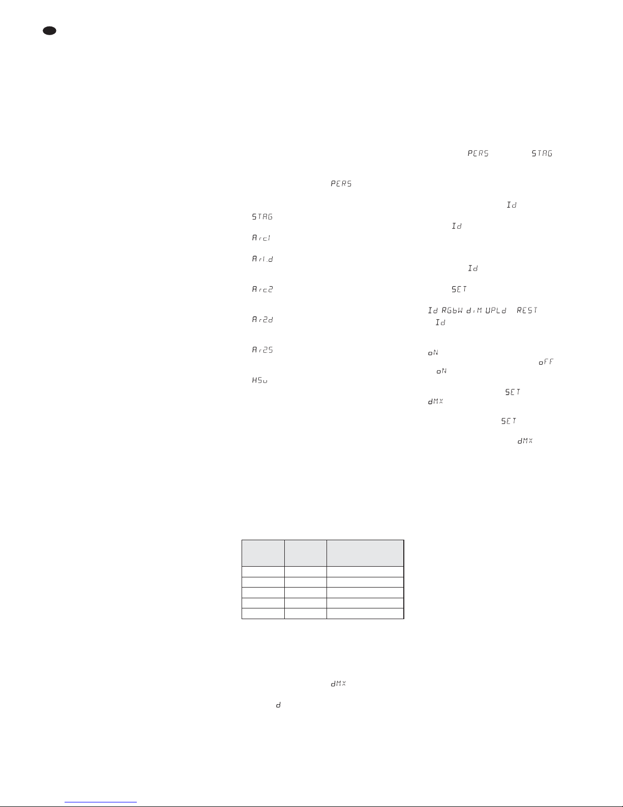
7.4 Scheinwerfer auf die
Werkseinstellung zurücksetzen
Ab Werk ist der Scheinwerfer wie folgt eingestellt:
Funktion Werkseinstellung
Farbstrahler R = 255, G = 255,
B = 255, W = 030,
S = 00
Showprogramme AT.01
Einstellung für den
Master-Slave-Modus Nebengerät
DMX-Startadresse 001
Anzahl DMX-Kanäle = 11 Kanäle
Unteradresse 01
Funktion Unteradresse aus (off)
Funktion Weißabgleich aus (off)
träge LED-Reaktion aus (off)
11 Weißtöne Werte ab Werk
Weißabgleich R = 255, G = 255,
B = 255
Tastensperre aus (off)
Zum Zurücksetzen des Scheinwerfers auf die
Werkseinstellung:
1) Die Taste MENU so oft drücken, bis die
oberste Menüebene erreicht ist.
2) Die Taste UP oder DOWN so oft drücken, bis
das Display anzeigt.
3) Die Taste ENTER drücken. Das Display
springt auf die Anzeige , , ,
oder um.
4) Wird nicht angezeigt, die Taste UP
oder DOWN entsprechend oft drücken.
5) Die Taste ENTER drücken. Das Display er -
lischt. Dann folgende Tasten drücken:
UP, DOWN, UP, DOWN.
Das Drücken dieser Tasten wird jeweils mit
einem Stern ( ) im Display angezeigt.
Das Zurücksetzen mit der Taste ENTER starten.
6) Danach mit der Taste MENU zurück auf die
Anzeige schalten. Mit der Taste UP oder
DOWN die Betriebsart auswählen und mit
der Taste ENTER aktivieren.
8 Technische Daten
Datenprotokoll: . . . . . . . . DMX 512
Anzahl der DMX-Kanäle: wählbar zwischen
3, 4, 5, 6 oder 11
Lichtquelle: . . . . . . . . . . . 12 RGBW-LEDs
Leistung je LED: . . . . . 8 W
Abstrahlwinkel: . . . . . . 25°
Stromversorgung: . . . . . . 230 V~ / 50 Hz
Leistungsaufnahme: . . . . max. 120 VA
Gehäuseschutzart: . . . . . IP 67
Abmessungen: . . . . . . . . ∅ 230 mm × 210 mm
Gewicht: . . . . . . . . . . . . . 5,8 kg
Änderungen vorbehalten.
D
A
CH
8
Diese Bedienungsanleitung ist urheberrechtlich für MONACOR
®
INTERNATIONAL GmbH & Co. KG
geschützt. Eine Reproduktion für eigene kommerzielle Zwecke – auch auszugsweise – ist untersagt.

9
10
GB
All operating elements and connections de scribed can be found on the fold-out page 3.
1 Operating Elements
and Connections
1 Plug of the cable POWER IN for the power
supply (230 V~ / 50 Hz):
either connect it to a socket via the cable with
the mains plug (4)
or to the inline jack of the cable POWER OUT
(2) of another ODP-1210RGBW
2 Connection cable POWER OUT for the
power supply of another ODP-1210RGBW
3 Connection cable DMX OUT: DMX signal
output for connection to the DMX signal input
of another ODP-1210RGBW
4 Mains plug for connection to a socket (230 V~ /
50 Hz)
5 XLR plug of the DMX signal input
pin 1 = ground, pin 2 = DMX
-
, pin 3 = DMX+
6 Plug of the cable DMX IN for the DMX signal
input:
either connect it to a light controller via the
cable with the XLR plug (5)
or to the DMX signal output of another DMXcontrolled unit
7 Locking screws (2 ×) for the mounting / set-up
brackets
8 Mounting / set-up brackets
9 Buttons to select the operating mode and to
change adjustments, see fig. 2
10 Display
2 Safety Notes
The unit corresponds to all relevant directives of
the EU and is therefore marked with .
Please observe the following items in any case:
G
Do not operate the unit and immediately disconnect the mains plug from the mains socket
1. if the unit or the mains cable is visibly damaged,
2. if a defect might have occurred after the unit
was dropped or suffered a similar accident,
3. if malfunctions occur.
In any case the unit must be repaired by
skilled personnel.
G
A damaged mains cable must only be re placed by skilled personnel.
G
Never pull the mains cable for disconnecting
the mains plug from the socket, always seize
the plug.
G
For cleaning the spotlight housing and the
protective pane in front of the LEDs only use a
mild detergent.
G
No guarantee claims for the unit and no liability for any resulting personal damage or material damage will be accepted if the unit is used
for other purposes than originally intended, if it
is not safely mounted or not correctly operated, or if it is not repaired in an expert way.
G
Important for U. K. Customers!
The wires in this mains lead are coloured in ac cord ance with the following code:
green/yellow = earth
blue = neutral
brown = live
As the colours of the wires in the mains lead of
this appliance may not correspond with the
coloured markings identifying the terminals in
your plug, proceed as follows:
1. The wire which is coloured green and yellow must be connected to the terminal in the
plug which is marked with the letter E or by
the earth symbol , or coloured green or
green and yellow.
2. The wire which is coloured blue must be
connected to the terminal which is marked
with the letter N or coloured black.
3. The wire which is coloured brown must be
connected to the terminal which is marked
with the letter L or coloured red.
Warning – This appliance must be earthed.
3 Applications
This LED spotlight serves for effect illumination.
The spotlight has a weatherproof aluminium
housing (IP 67) and is therefore also suitable for
outdoor applications. As a light source, 12 extra
bright LEDs are used. The spotlight is designed
for control via a DMX controller (optionally 11, 6,
5, 4 or 3 DMX control channels). However, it can
also be operated on its own without controller.
As a special feature the ODP-1210RGBW
offers the use off 66 subaddresses when DMXcontrolled. Thus, up to 66 spotlights (spotlight
groups) can be controlled independently of each
other via a single DMX start address, and the
number of DMX-controlled units which is possible as a maximum is considerably increased.
The selection of spotlights with a subaddress is
made via the DMX channel 11.
4 Mounting
G
Always place the unit so that a sufficient air
circulation is ensured during operation.
G
The distance to the radiated object should be
50 cm as a minimum.
1. Fix the spotlight via the mounting brackets (8),
e. g. with a stable mounting screw or a support for lighting units (C hook) to a crossbar.
To align the spotlight, release the two locking screws (7) at the mounting brackets.
Adjust the desired inclination of the spotlight
and retighten the screws.
2. As an alternative the spotlight can also be set
up as desired: Spread the mounting brackets
under the spotlight so that they serve as a
support. Then tighten the locking screws.
5 Setting into Operation
Connect the plug (1) of the cable POWER IN to
the inline jack of the supplied cable with the
mains plug (4) and screw together the plug connection with the cap nut. Connect the mains plug
to a socket (230 V~ / 50 Hz). Then the spotlight is
switched on. The display (10) shows the last
menu setting for a few seconds (fig. 2) and will
then be extinguished.
CAUTION! If no further spotlight is connected to
the cables POWER OUT (2) and DMX OUT (3),
always screw the supplied protective covers
onto the inline jacks. The cable POWER OUT
carries mains voltage.
5.1 Connection of several spotlights
If several ODP-1210RGBW are used, the spotlights can be interconnected for power supply.
Do not yet connect the first spotlight to a socket
for the time being.
1) Connect the first spotlight via the inline jack of
the cable POWER OUT (2) to the plug (1) of
the cable POWER IN of the second spotlight.
Connect the second spotlight to the third
spotlight in the same way etc. until all units
have been connected in a chain.
If the mains connection cables between
the spotlights should be too short, use suitable extension cables, e. g. ODP-34AC (2m)
or ODP-34AC / 10 (10 m)
2) Screw the supplied protective cover at the
last spotlight onto the inline jack of the cable
POWER OUT (2). The cable carries mains
voltage.
3) Finally connect the mains plug of the first
spotlight to a socket (230 V~ / 50 Hz).
6 Operation
The operational buttons MENU, UP, DOWN and
ENTER (9) serve to select the operating mode
and different functions. Fig. 2 on page 3 shows
how the modes and functions are selected via a
menu.
A few seconds after pressing a button the
display (10) will be extinguished. As soon as a
button is actuated, it will light up again.
Note: The unit is protected against overheating. Thus, it
will be switched off when the temperature is too high and
be switched on again automatically after cooling down.
6.1 Individual operation
For the individual operation adjust the spotlight
with its operational buttons (9) to the desired
mode.
WARNING Never look directly into the light
source for a longer time, this may
cause eye damage.
Please note that fast changes in
lighting may trigger epileptic
seizures with photosensitive persons or persons with epilepsy!
WARNING The total current in the connec-
tion cables (1, 2) must not
exceed 10 A, otherwise a cable
fire may occur due to overload.
Therefore, only interconnect
19 spotlights as a maximum.
WARNING The spotlight must be mounted in
a safe and expert way. If it is
installed at a place where people
may walk or sit under, it must ad ditionally be secured (e. g. by a
safety rope at the mounting brackets; fix the safety rope so that the
maximum falling distance of the
unit would not exceed 20 cm).
If the unit is to be put out of operation
definitively, take it to a local recycling
plant for a disposal which is not harmful
to the environment.
WARNING
The unit uses hazardous mains
voltage. Leave servicing to skilled
personnel only; inexpert handling
may result in electric shock.
6.1.1 Colour radiator and stroboscope
In this mode the spotlight constantly radiates
light in an adjustable colour. In addition, the stroboscope function can be switched on.
1) Press the button MENU repeatedly until the
highest menu level is reached (in fig. 2 on the
very left).
2) Press the button UP or DOWN repeatedly
until the display shows .
3) Press the button ENTER. The display now
shows , , , or and a number.
= brightness of red (0 – 255)
= brightness of green (0 – 255)
= brightness of blue (0– 255)
= brightness of white (0 – 255)
= flash frequency (0– 20 Hz) of the strobo-
scope
4) Select the five adjusting functions successively with the button ENTER and adjust the
brightness or the flash frequency with the button UP or DOWN.
Hint: When adjusting the brightness of the colours
red, green or blue, not only their brightness changes
but also the shade of colour in case the colours are
mixed. Therefore, first adjust the colour which is to
dominate to the desired brightness and then add the
other two colours. If the intended colour mixture is
white, first adjust the brightness of the green colour
because this appears to be the brightest colour to the
human eye. Then add red to result in yellow and
finally add blue to result in white.
6.1.2 Different shades of white
Memorizing 11 shades of colour
In this mode the spotlight radiates white light. 11
different shades of white are memorized which,
however, can be changed. For each shade of
white the brightness of the colours red, green,
blue and white can be adjusted differently so that
this mode can also be used to memorize 11 individual shades of colour.
1) Press the button MENU repeatedly until the
highest menu level is reached (in fig. 2 on the
very left).
2) Press the button UP or DOWN repeatedly
until the display shows .
3) Press the button ENTER. The display now
shows one of the 11 memory locations (
… ) and the LEDs light up in the corresponding shade of white.
4) Use the button UP or DOWN to select the
desired shade of white or the memory location whose adjustments should be changed.
5) To change an adjustment, select the memory
location, then press the button ENTER. The
display now shows , , or and a number
(0 – 255).
= brightness of red
= brightness of green
= brightness of blue
= brightness of white
6) Select the four colours successively with the
button ENTER and use the button UP or
DOWN to adjust the brightness in each case.
7) To select another shade of white or to change
the adjustments of another memory location,
press the button MENU so that the number of
the memory location is displayed again. Then
repeat steps 4 to 6.
6.1.3 Show programmes and
sequences of scenes
10 show programmes ( … ) are memorized in the spotlight. Furthermore, 10 se quences of scenes ( … ) with up to
30 scenes can be programmed individually
(
chapter 6.1.4). The show programmes and
sequences of scenes can be started as follows:
1) Press the button MENU repeatedly until the
highest menu level is reached (in fig. 2 on the
very left).
2) Press the button UP or DOWN repeatedly
until the display shows .
3) Press the button ENTER. The display now
shows the last show programme called (
… ) or the last sequence of scenes
called ( … ).
4) Select the show programme or the sequence
of scenes with the button UP or DOWN.
The show programmes have the following
sequence:
Fig. 3 Show programmes AT.01 – AT.10
6.1.4 Programming sequences of scenes
10 sequences of scenes can easily be programmed. A sequence of scenes may consist of
30 scenes as a maximum which change automatically in succession. For each scene, the
colour can be adjusted together with the brightness, the stroboscope function can be activated
at variable flash frequency, the time of scene
and the fading time can be defined.
1) Press the button MENU repeatedly until the
highest menu level is reached (in fig. 2 on the
very left).
2) Press the button UP or DOWN repeatedly
until the display shows .
3) Press the button ENTER. The display shows
the number of the last sequence of scenes
selected ( … ).
4) Select the number under which the sequence
of scenes is to be memorized with the button
UP or DOWN and press the button ENTER.
The display shows the number of the first
scene ( ).
5) Each time the button ENTER is pressed, the
following adjusting functions are called in
succession:
= brightness of red
= brightness of green
= brightness of blue
= brightness of white
= flash frequency of the stroboscope
= time of scene, 100 = 60 seconds
= fading time
Adjust the desired value in each case with the
button UP or DOWN.
Notes
1. The time of a scene must at least be adjusted to
the value 001, otherwise the scene following it
cannot be programmed.
2. For fading from one scene to the next, a fading
time has to be adjusted for both scenes.
6) After the first scene has been adjusted, press
the button MENU. The display shows the
number of scene again. Select the second
scene with the button UP, press the button
ENTER, adjust the scene and repeat the procedure for all following scenes.
7) After the last scene has been adjusted, memorize the sequence of scenes: Keep the button ENTER pressed for 5 seconds. After re leasing the button, the display must show the
number of the sequence of scenes ( …
), otherwise the button ENTER has not
been pressed long enough.
Notes
1. A sequence of scenes must completely be pro-
grammed before the spotlight is disconnected from the
power supply. After switching on again, a sequence of
scenes cannot be changed any more; it can only be
programmed again. To overwrite a sequence of
scenes, it is not necessary to delete the scenes programmed before.
2. If the sequences of scenes are not called with the
operational buttons (9) [chapter 6.1.3] but via a DMX
light controller, the DMX channel 2 defines the time of
scene and channel 3 the fading time (chapter 6.3.5).
Channel 2 must at least be adjusted to a DMX value of
001, otherwise the spotlight remains dark.
6.2 Synchronous control of several
spotlights (master/slave mode)
Several ODP-1210RGBW can be interconnected. The master unit can then control all
slave units in sync.
1) Interconnect the spotlights in each case via
the inline jack of the cable DMX OUT (3) and
the plug (6) of the cable DMX IN to a chain.
See chapter 6.3.1 “DMX connection”, however, without paying attention to step 1.
2) For the master/slave mode the spotlight is
factory-set as a slave unit. Thus, only the
spotlight intended to control the slave units
has to be adjusted as the master unit. To
change the setting:
a) Press the button MENU repeatedly until
the highest menu level is reached (in fig. 2
on the very left).
b) Press the button UP or DOWN repeatedly
until the display shows .
c) Press the button ENTER and select with
the button UP or DOWN:
= master unit
= slave unit
3) If sequences of scenes were programmed at
the master unit (chapter 6.1.4), these se quences can be copied to the slave units:
a) Press the button MENU at the master unit
repeatedly until the highest menu level is
reached (in fig. 2 on the very left).
b) Press the button UP or DOWN repeatedly
until the display shows .
c) Press the button ENTER. The display
shows , , , or .
d) If is not shown, press the button UP
or DOWN as many times as necessary.
e) Press the button ENTER. The display will
be extinguished. Then press the following
buttons:
UP, DOWN, UP, DOWN.
Each time one of these buttons is pressed,
the display shows an asterisk ( ).
f) Press the button ENTER to start the copy-
ing procedure. While copying, the slave
units show yellow, they show red if an
error oc curs and green after copying successfully.
g) To switch on the desired operating mode,
press the button MENU repeatedly until
the display shows again. Select the
Show -
programme
Sequence
AT.01 stroboscope: white light
AT.02 fading in / out: red, green, blue, white
AT.03 change of colour: red, green, blue, white
AT.04
change of colour: red, off, green, off,
blue, off, white, off
AT.05
fading: green © red © blue
AT.06 fading in/out: purple, yellow
AT.07 fading in / out: purple, yellow
AT.08 fading in / out: purple
AT.09 fading in / out: cyan, purple
AT.10 fading in / out: purple, green
11
GB
operating mode with the button UP or
DOWN and activate it with the button
ENTER.
6.3 Operation with a DMX controller
DMX is short for Digital Multiplex and means digital control of several DMX units via a common
control line. For operation via a DMX controller
(e. g. DMX-1440 or DMX-510USB from “img
Stage Line”) the spotlight is equipped with 11
DMX control channels. However, it can also be
controlled via 6, 5, 4 or 3 channels only, depending on the requirement. The functions of the
channels and the DMX values are indicated in
chapter 6.3.5.
6.3.1 DMX connection
For the DMX connection, the unit is provided
with 3-pole XLR jacks of the following pin configuration:
pin 1 = ground, 2 = DMX
-
, 3 = DMX+
For connection, special cables for the DMX signal transmission should be used (e. g. cables of
the CDMXN series from “img Stage Line”). For
cable lengths exceeding 150 m it is recommended to insert a DMX level matching amplifier
(e. g. SR-103DMX from “img Stage Line”).
1) Connect the plug (6) of the cable DMX IN to
the inline jack of the supplied cable with the
XLR plug (5) and screw together the plug
connection with the cap nut. Connect the
XLR plug via an extension cable to the DMX
output of the controller or, if further DMX-controlled units are used, to the DMX output of
the last DMX-controlled unit of the DMX signal cable.
2) If further spotlights
ODP-1210RGBW
are
used, connect the first spotlight via the inline
jack of the cable DMX OUT (3) to the plug (6)
of the cable DMX IN of the second spotlight.
Connect the second spotlight to the third
spotlight in the same way etc. until all units
have been connected in a chain.
If the DMX connection cables between the
spotlights should be too short, use suitable
extension cables, e. g.
ODP-34DMX (length 2 m) or
ODP-34DMX / 10 (length 10 m).
3) If the DMX control should not function correctly during the operation, terminate the
DMX output of the last unit of the chain with a
120 Ω resistor (> 0.3 W). To terminate the
DMX output of an
ODP-1210RGBW
, the
easier way is to separate an extension cable
ODP-34DMX and to connect the resistor to
the pins 2 and 3 of the plug. Connect the plug
with the resistor to the inline jack of the cable
DMX OUT.
6.3.2 Adjusting the number of DMX channels
To be able to operate the ODP-1210RGBW with
a light controller, the DMX start address
(chapter 6.3.3) and the number of DMX channels have to be adjusted. The number of DMX
channels depends on the required functions and
possibly on the number of the control channels
available at the controller. Chapter 6.3.5 provides the information about the functions which
are pos sible for 3-channel, 4-channel, 5-channel, 6-channel and 11-channel operation. Select
the number of DMX channels accordingly:
1) Press the button MENU repeatedly until the
highest menu level is reached (in fig. 2 on the
very left).
2) Press the button UP or DOWN repeatedly
until the display shows .
3) Press the button ENTER. The display shows
the present adjustment:
11 channels
(
chapter 6.3.5, figs. 11 + 12)
3 channels
1 = red, 2 = green, 3 = blue
4 channels
1 = dimmer, 2 = red,
3 = green, 4 = blue
4 channels
1 = red, 2 = green,
3 = blue, 4 = white
5 channels
1 = dimmer, 2 = red, 3 = green,
4 = blue, 5 = white
6 channels
1 = dimmer, 2 = red, 3 = green,
4 = blue, 5 = white, 6 = stroboscope
3 channels
1 = colour, 2 = colour saturation,
3 = brightness
4) Select the adjustment with the button UP or
DOWN.
6.3.3 Adjusting the DMX start address
To be able to operate the spotlight with a light
controller, adjust the DMX start address for the
first DMX channel. If e. g. address 17 on the DMX
controller is to be used to control the function of
the first DMX channel, adjust the start address
17 on the ODP-1210RGBW. The other DMX
channels of the ODP-1210RGBW are then automatically assigned to the following addresses.
An example with the start address 17 is shown
below:
Fig. 4 DMX address configuration when using the start
address 17
1) Press the button MENU repeatedly until the
highest menu level is reached (in fig. 2 on the
very left).
2) Press the button UP or DOWN repeatedly
until the display shows .
3) Press the button ENTER. The display now
shows and a number between 1 and 512.
4) Adjust the start address with the button UP or
DOWN.
Note: A point flashes on the display when the spotlight
receives DMX signals.
6.3.4 Using subaddresses
By using subaddresses, up to 66 spotlights
(spotlight groups) can be controlled independently of each other via a single DMX start
address. Thus, the number of DMX-controlled
units which is possible as a maximum is considerably increased. The selection of spotlights with
a subaddress is made via the DMX channel 11
(fig. 12). All spotlights with a subaddress may be
controlled in sync if the DMX channel 11 is
adjusted to a DMX value less than 10.
1) Adjust the spotlight for the control of 11 DMX
channels,
chapter 6.3.2
(menu item , adjustment ).
2) Press the button MENU repeatedly until the
highest menu level is reached (in fig. 2 on the
very left).
3) Press the button UP or DOWN repeatedly
until the display shows .
4) Press the button ENTER. The display now
shows and a number between 1 and 66.
5) Adjust the subaddress with the button UP or
DOWN.
6) Press the button MENU so that the display
only shows again.
7) Press the button UP twice so that the display
shows .
8) Press the button ENTER. The display shows
, , , or .
9) If is not shown, press the button UP or
DOWN as many times as necessary.
10) Press the button ENTER. If the display shows
, the function for the selection of subaddresses is activated, if it shows , switch
to with the button UP or DOWN.
11) To be able to control the spotlight by DMX, go
from the menu branch to the menu item
:
a) Press the button MENU repeatedly until
the display shows again.
b) Press the button UP or DOWN repeatedly
until the display shows .
c) Press the button ENTER. The display
shortly shows the DMX start address. If
DMX control signals are received now, a
point flashes on the display.
12) To be able to operate the spotlight, adjust the
DMX channel 11 on the controller to the DMX
value which corresponds to the subaddress
of the spotlight (
chapter 6.3.5, fig. 12).
Number of
DMX channels
Reserved
DMX addresses
Next possible start address
for the following DMX unit
3 17 – 19 20
4 17 – 20 21
5 17 – 21 22
6 17 – 22 23
11 17 – 27 28
12
GB
 Loading...