

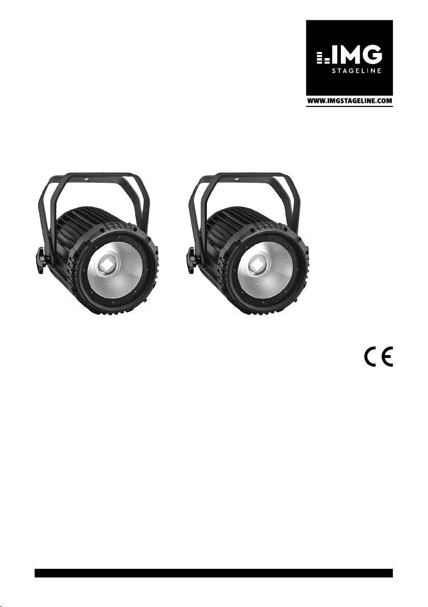
DMX-LED-Scheinwerfer
DMX LED Spotlight
ODC-100/WS
Bestell-Nr. • Order No. 38.7100
BEDIENUNGSANLEITUNG
INSTRUCTION MANUAL
MODE D’EMPLOI
ISTRUZIONI PER L’USO
GEBRUIKSAANWIJZING
MANUAL DE INSTRUCCIONES
INSTRUKCJA OBSŁUGI
SIKKERHEDSOPLYSNINGER
SÄKERHETSFÖRESKRIFTER
TURVALLISUUDESTA
ELECTRONICS FOR SPECIALISTS ELECTRONICS FOR SPECIALISTS ELECTRONICS FOR SPECIALISTS ELECTRONICS FOR SPECIALISTS
PARC-100/WS
Bestell-Nr. • Order No. 38.7130
SAFETY
ROPE
POWER IN POWER OUT
DMX IN DMX OUT
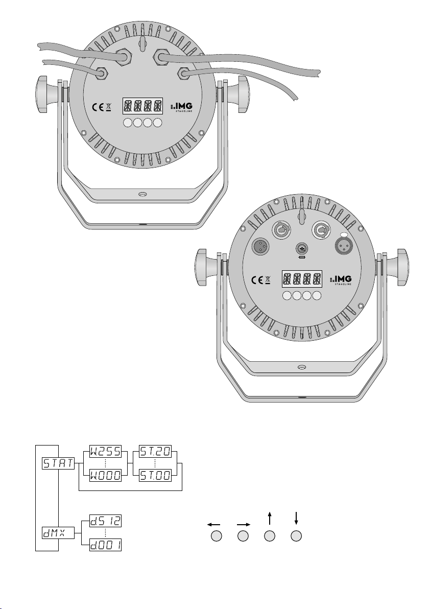
MENU DOWN UP ENTER
ODC-100/ WS
➀
SAFETY
ROPE
POWER IN POWER OUT
F
U
S
DMX IN DMX OUT
E
FUSE
MENU DOWN UP ENTER
PUSH
DMX-Steuerung
DMX control
Gestion DMX
Comando DMX
Menüstruktur • Menu structure
➂
Structure du menu • Struttura del menù
PARC-100/ WS
➁
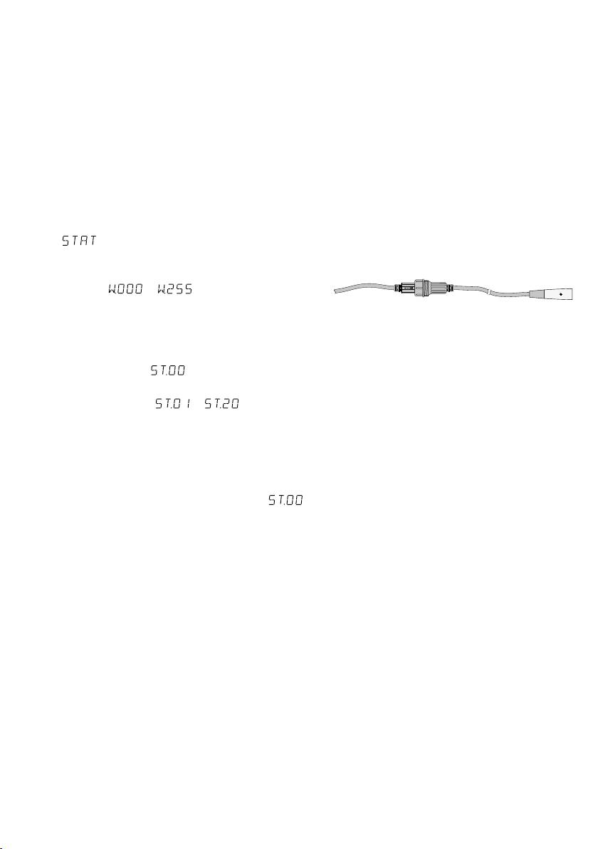
Eigenständiger Betrieb: W = Helligkeit, ST = Blitzfrequenz
Independent operation: W = brightness, ST = flash rate
Fonctionnement indépendant : W = luminosité, ST = fréquence des éclairs
Funzionamento autonomo: W = luminosità, ST = frequenza lampi
ENTER UP DOWNMENU

Deutsch ..........Seite 4
English ...........Page 8
Français ..........Page 12
Italiano...........Pagina 16
Nederlands .......Pagina 20
Español ..........Página 24
Polski ............Strona 28
Dansk ............Sida 32
Svenska ..........Sidan 33
Suomi............Sivulta 34
ELECTRONICS FOR SPECIALISTS ELECTRONICS FOR SPECIALISTS ELECTRONICS FOR SPECIALISTS ELECTRONICS FOR SPECIALISTS
3
DMX-LED-Scheinwerfer
Die Bedienung des Geräts ist einfach und auf
Bediener mit Grundkenntnissen in der DMX-Steu-
Deutsch
erung ausgerichtet. Bitte lesen Sie trotzdem die
Anleitung vor dem Betrieb gründlich durch und
heben Sie sie für ein späteres Nachlesen auf.
Auf der Seite 2 sind die Modelle ODC-100 / WS
und PARC-100 / WS sowie die Menüstruktur
abgebildet.
1 Einsatzmöglichkeiten
Dieser LED-Scheinwerfer dient zur Beleuchtung
z. B. auf Bühnen, in Diskotheken und Festsälen.
Als Lichtquelle ist eine lichtstarke weiße COB-LED
eingesetzt (COB = Chip-on-Board-Techno logie):
Viele LED-Chips sind eng auf einer Leiterplatte
untergebracht, sodass eine gleichmäßige Lichtverteilung erreicht wird.
Der Scheinwerfer ist für die Steuerung über
ein DMX-Lichtsteuergerät ausgelegt (3 DMXSteuerkanäle), kann aber auch eigenständig ohne
Steuergerät betrieben werden. Der ODC-100 / WS
ist durch seine wetterfeste Ausführung (IP 66)
auch im Außenbereich einsetzbar.
2 Hinweise
fürdensicherenGebrauch
Das Gerät entspricht allen relevanten Richtlinien
der EU und trägt deshalb das -Zeichen.
WARNUNG Das Gerät wird mit lebensgefähr-
licher Netzspannung versorgt.
Nehmen Sie deshalb niemals
selbst Eingriffe am Gerät vor. Es
besteht die Gefahr eines elektrischen Schlages.
Das Modell PARC-100 / WS darf nur im Innen-
•
bereich gesetzt werden. Schützen Sie es vor
Tropf- und Spritzwasser, hoher Luftfeuchtigkeit
und Hitze (zulässiger Einsatztemperaturbereich
0 bis 40 °C).
Das Modell ODC-100 / WS ist für den Außenbereich geeignet (zulässiger Einsatztemperaturbereich −20 bis +40 °C).
Ziehen Sie sofort den Netzstecker aus der Steck-
•
dose,
1. wenn sichtbare Schäden am Gerät oder am
Netzkabel vorhanden sind,
2. wenn nach einem Sturz oder Ähnlichem der
Verdacht auf einen Defekt besteht,
4
3. wenn Funktionsstörungen auftreten.
Geben Sie das Gerät in jedem Fall zur Reparatur
in eine Fachwerkstatt.
Ziehen Sie den Netzstecker nie am Kabel aus
•
der Steckdose, fassen Sie immer am Stecker an.
Nur ODC-100 / WS: Ein beschädigtes Netz-
•
kabel darf nur durch eine Fachwerkstatt er setzt
werden.
Wird das Gerät zweckentfremdet, nicht sicher
•
montiert, nicht richtig angeschlossen, falsch
bedient oder nicht fachgerecht repariert, kann
keine Haftung für daraus resultierende Sachoder Personenschäden und keine Garantie für
das Gerät übernommen werden.
Soll das Gerät endgültig aus dem Betrieb
genommen werden, übergeben Sie es
zur umweltgerechten Entsorgung einem
örtlichen Recyclingbetrieb.
3 Inbetriebnahme
3.1 Montage
Platzieren Sie das Gerät so, dass im Betrieb eine
•
ausreichende Luftzirkulation gewährleistet ist.
Die Kühlrippen des Gehäuses dürfen auf keinen
Fall abgedeckt werden.
Der Abstand zum angestrahlten Objekt sollte
•
mindestens 50 cm betragen.
WARNUNG
durch ein Fangseil. Das Fangseil durch die Sicherheitsöse an der Geräterückseite führen und so
befestigen, dass der Fallweg des Geräts nicht
mehr als 20 cm betragen kann.
1. Den Scheinwerfer über die Montagebügel
befestigen, z. B. mit einer stabilen Montageschraube oder einer Lichtstrahler-Halterung
(C-Haken) an einer Traverse.
Feststellschrauben der Montagebügel lösen.
Die gewünschte Neigung des Scheinwerfers
einstellen und die Schrauben wieder festziehen.
2. Alternativ lässt sich der Scheinwerfer auch frei
aufstellen: Die Montagebügel so unter dem
Scheinwerfer spreizen, dass sie als Ständer dienen. Die Feststellschrauben da nach festdrehen.
Wird das Gerät an einer Stelle
installiert, unter der sich Personen aufhalten können, muss es
zu sätzlich gesichert werden, z. B.
Zum Ausrichten des Scheinwerfers die zwei
3.2 Torblende
Um den Lichtstrahl einzuengen, lässt sich die als
Zubehör erhältliche Torblende PARC-100B an der
Vorderseite festschrauben.
3.3 Stromversorgung
Mit dem Anschluss des Scheinwerfers ans Stromnetz ist er eingeschaltet. Das Display zeigt den
zuletzt gewählten Menüpunkt und erlischt nach
30 s. Sobald eine Taste (MENU, UP, DOWN oder
ENTER) gedrückt wird, leuchtet es wieder für 30 s.
WARNUNG
Blicken Sie nicht für längere Zeit
direkt in die Lichtquelle, das kann
zu Augenschäden führen.
Beachten Sie, dass sehr schnelle Lichtwechsel
bei Epileptikern und bei fotosensiblen Menschen
epileptische Anfälle auslösen können!
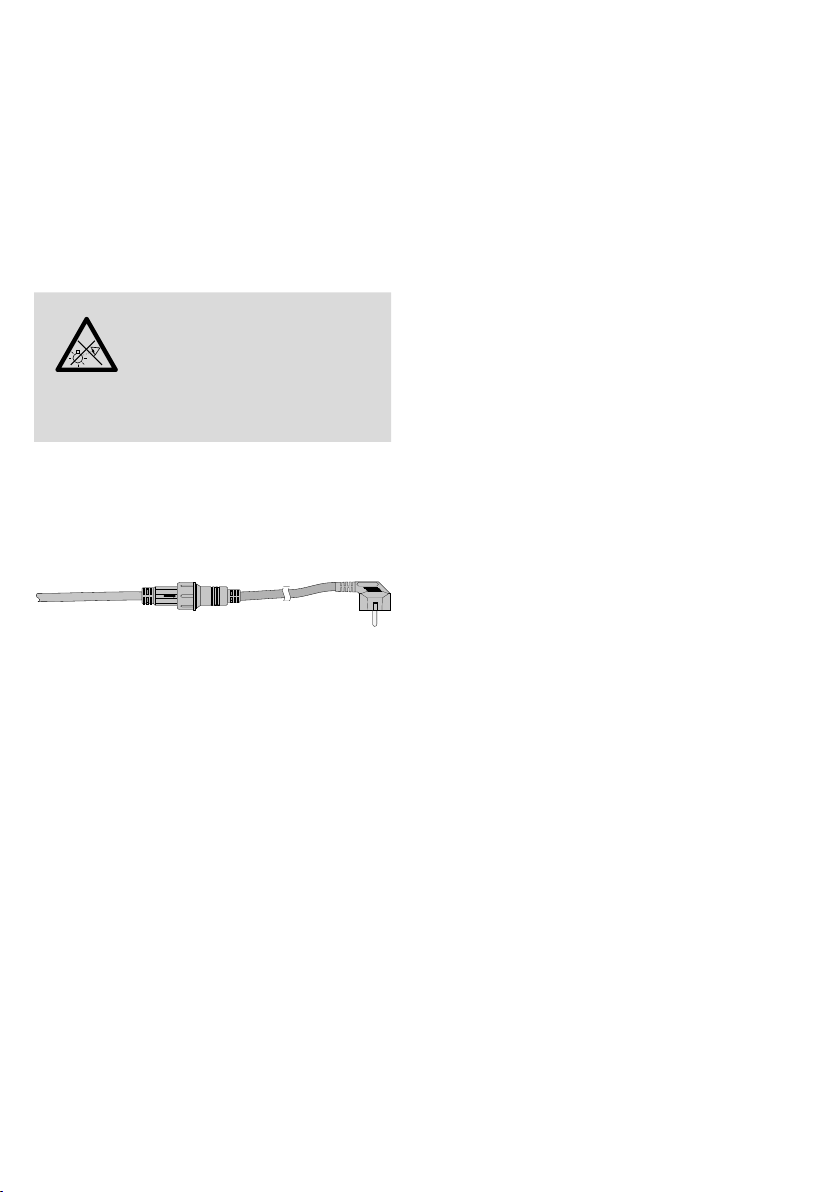
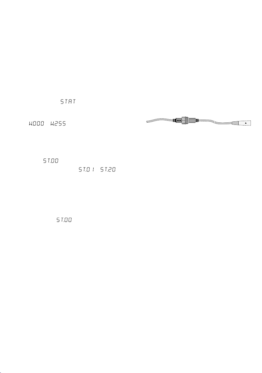
3.3.1 ODC-100 / WS
Den Stecker (A) des Kabels POWER IN in die Kupplung (B) des beiliegenden Netzkabels stecken. Den
Stecker und die Kupplung mit der Überwurfmutter zusammenschrauben.
POWER IN
Abb. 4 Netzanschluss ODC-100 / WS
VORSICHT! Das Kabel POWER OUT führt Netzspannung. Ist kein weiteres Gerät an den Kabeln
POWER OUT und DMX OUT angeschlossen, unbedingt die beiliegenden Schutzkappen auf die
Kupplungen schrauben.
Den Netzstecker in eine Steckdose (230 V/ 50 Hz)
stecken.
Stromversorgung mehrerer ODC-100 / WS
Werden mehrere ODC-100 / WS eingesetzt, können die Geräte zur Stromversorgung mitein ander
verbunden werden. Das erste Gerät vorerst noch
nicht an eine Steckdose an schließen.
1)
Das 1. Gerät über die Kupplung des Kabels
POWER OUT mit dem Stecker (A) des Kabels
POWER IN des 2. Geräts verbinden. Genauso
das 2. Gerät mit dem 3. Gerät. verbinden usw.,
bis alle Geräte in einer Kette angeschlossen
sind.
Sollten die Netzverbindungskabel zwischen
den Geräten zu kurz sein, passende Verlängerungskabel verwenden, z. B.:
A B
230 V/50 Hz
ODP-34AC Länge 2 m oder
ODP-34AC / 10 Länge 10 m.
VORSICHT! Der Gesamtstrom in den Anschlusskabeln darf 10 A nicht überschreiten,
sonst kann durch Überlastung ein Kabelbrand
entstehen. Darum nur maximal 19 Ge räte
ODC-100 / WS miteinander verbinden.
2)
Am letzten Gerät auf die Kupplung des Kabels
POWER OUT die beiliegende Schutzkappe
schrauben. Das Kabel führt Netzspannung!
3)
Den Netzstecker des ersten Geräts in eine
Steckdose (230 V/ 50 Hz) stecken.
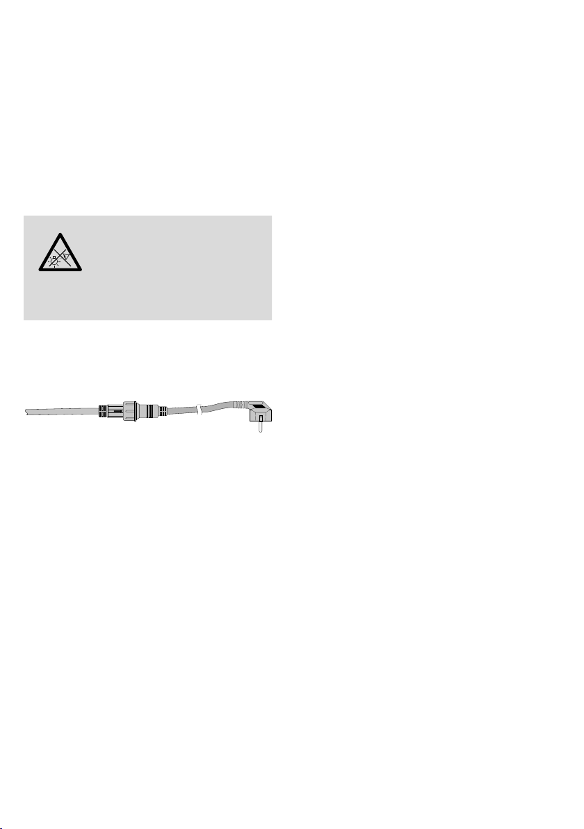
3.3.2 PARC-100 / WS
Zur Stromversorgung ist das Gerät mit Powercon-Anschlüssen ausgestattet.
VORSICHT! Ein Powercon-Stecker darf nicht
unter Spannung hineingesteckt oder herausgezogen werden. Stellen Sie darum immer zuerst die
Powercon-Verbindung her, dann die Verbindung
zur Netzsteckdose und trennen Sie die Verbindung zur Netzsteckdose immer vor der Powercon-Verbindung.
Die Netzbuchse POWER IN mit dem beiliegenden Netzkabel an eine Steckdose (230 V/ 50 Hz)
anschließen. Den blauen Powercon-Stecker des
Kabels nach dem Einstecken in die Netzbuchse
zum Einrasten nach rechts drehen. Zum späteren
Herausziehen den Sicherungsriegel am Stecker
zurückziehen und den Stecker nach links drehen.
Stromversorgung mehrerer PARC-100 / WS
Werden mehrere PARC-100 / WS verwendet, lässt
die Buchse POWER OUT des ersten Geräts mit
der Netzbuchse POWER IN des zweiten Geräts
verbinden. Dazu wird ein Netzkabel mit Powercon-Steckern (NAC-3FCB und NAC-3FCA) benötigt. Das zweite Gerät ge nauso mit dem dritten
Gerät verbinden usw., bis alle Geräte in einer
Kette angeschlossen sind. Auf diese Weise dürfen maximal 19 Geräte miteinander verbunden
werden. Die Buchse POWER OUT kann auch zur
Stromversorgung anderer (Lichteffekt-) Geräte
genutzt werden.
VORSICHT! Die Kabel und der Netzstecker dürfen nicht mit einem Strom über 10 A belastet
werden, sonst kann durch Überlastung ein Brand
entstehen.
Deutsch
5
4 Bedienung
Die Wahl des Betriebsmodus und der Einstellfunktionen erfolgt über ein Menü mit den Tasten
Deutsch
MENU, ENTER, UP und DOWN. Die Abbildung 3
auf der Seite 2 zeigt, wie die Modi und Funktionen über das Menü angewählt und vom Display
angezeigt werden.
4.1 Eigenständiger Betrieb
Hierfür lässt sich am Scheinwerfer die Helligkeit
einstellen, die Stroboskop-Funktion einschalten
und die Blitzfrequenz einstellen.
1)
Die Taste MENU so oft drücken, bis das Display
anzeigt.
2)
Die Taste ENTER ein- oder zweimal drücken,
sodass das Display die eingestellte Helligkeit
anzeigt ( … ).
3)
Mit den Tasten UP und DOWN die ge wünschte
Helligkeit einstellen.
4)
Soll die Stroboskop-Funktion eingeschaltet
werden, die Taste ENTER erneut drücken, sodass das Display anzeigt.
5)
Mit den Tasten UP und DOWN die Blitzfrequenz einstellen ( … ).
6)
Zum Ändern der Blitzhelligkeit mit der Taste
ENTER auf den Menüpunkt für die Helligkeit
zurückschalten und den Wert mit der Taste UP
oder DOWN ändern.
7)
Soll die Stroboskop-Funktion wieder ausgeschaltet werden, die Blitzfrequenz auf
einstellen.
Hinweis: Vor dem Ausschalten des Scheinwerfers den
Menüpunkt für die Helligkeit oder Blitzfrequenz nicht
mit der Taste MENU verlassen. Anderenfalls bleibt der
Scheinwerfer nach dem Wiedereinschalten dunkel.
4.2 Betrieb mit einem
DMX-Steuergerät
Zur Bedienung über ein DMX-Lichtsteuergerät
(z. B. DMX-1440 oder DMX-510USB von IMG
STAGELINE) verfügt der Scheinwerfer über drei
DMX-Steuerkanäle. DMX ist die Abkürzung für
Digital Multiplex und bedeutet digitale Steuerung
von mehreren DMX-Geräten über eine gemeinsame Steuerleitung. Die Funktionen der Kanäle
und die DMX-Werte sind im Kapitel 4.2.3 (Abb. 6)
angegeben.
4.2.1 Anschluss
Für die DMX-Signalübertragung sollten spezielle
Kabel verwendet werden (z. B. CDMXN-… von
IMG STAGELINE). Bei Leitungslängen ab 150 m
oder bei der Steuerung von mehr als 32 Geräten
über einen DMX-Ausgang wird grundsätzlich das
Zwischenschalten eines DMX-Aufholverstärkers
empfohlen (z. B. SR-103DMX).
1) Den Eingang DMX IN mit dem DMX-Ausgang
des Lichtsteuergeräts oder eines DMX-gesteuerten Geräts verbinden.
Bei dem Modell ODC-100 / WS den Stecker
(C) der Leitung DMX IN in die Kupplung (D)
der beiliegenden Leitung mit dem XLR-Stecker
stecken. Den Stecker und die Kupplung mit der
Überwurfmutter zusammenschrauben.
DMX IN C
Abb. 5 DMX-Anschluss ODC-100 / WS
D
Den XLR-Stecker über ein Verlängerungs kabel
an den DMX-Ausgang des Lichtsteuergeräts
anschließen oder, wenn weitere DMX-gesteuerte Geräte verwendet werden, an den
DMX-Ausgang des letzten DMX-gesteuerten
Geräts.
2)
Den Ausgang DMX OUT mit dem DMX-Eingang des nächsten DMX-Geräts verbinden.
Dessen Ausgang wieder mit dem Eingang des
nachfolgenden DMX-Geräts verbinden usw.,
bis alle DMX-gesteuerten Geräte in einer Kette
angeschlossen sind.
Sind beim Verbinden von mehreren ODC100 / WS miteinander die DMX-Verbindungskabel zwischen den Geräten zu kurz, passende
Verlängerungskabel verwenden, z. B.
ODP-34DMX Länge 2 m oder
ODP-34DMX / 10 Länge 10 m.
3)
Um Störungen bei der Signalübertragung auszuschließen, sollte bei langen Leitungen oder
bei einer Vielzahl von hintereinandergeschalteten Geräten der DMX-Ausgang des letzten
DMX-Geräts der Kette mit einem 120-Ω-Widerstand (> 0,3 W) abgeschlossen werden: In
die DMX-Ausgangsbuchse einen entsprechenden Ab schlussstecker (z. B. DLT-123) stecken.
Um den DMX-Ausgang des ODC-100 / WS
abzuschließen, ist es am einfachsten, ein
6
Verlängerungskabel ODP-34DMX aufzutrennen und den Widerstand mit den Pins 2 und
3 des Steckers zu verbinden. Den Stecker mit
dem Widerstand in die Kupplung des Kabels
DMX OUT stecken. Wird kein Abschlusswiderstand benötigt, auf die Kupplung des Kabels
die beiliegende Schutzkappe schrauben.
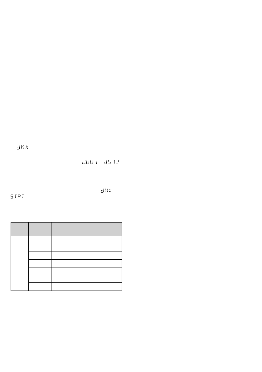
4.2.2 Startadresse einstellen
Um alle am Lichtsteuergerät angeschlossenen
DMX-Geräte separat bedienen zu können, muss
jedes Gerät eine eigene Startadresse erhalten.
Soll der erste DMX-Kanal des Scheinwerfers vom
Lichtsteuergerät z. B. über die DMX-Adresse 17
gesteuert werden, am Scheinwerfer die Startadresse 17 einstellen. Alle weiteren DMX-Kanäle
des Scheinwerfers sind dann automatisch den
darauffolgenden Adressen zugeordnet (z. B. bei
der Startadresse 17 die Adressen 18 und 19).
1)
Die Taste MENU so oft drücken, bis das Display
anzeigt.
2)
Die Taste ENTER drücken. Das Display zeigt die
eingestellte Startadresse an ( … ).
3)
Mit den Tasten UP und DOWN die ge wünschte
Adresse einstellen. Der Scheinwerfer lässt sich
jetzt mit dem Lichtsteuergerät bedienen.
Hinweis: Zeigt das Display den Menüpunkt oder
, blinkt ganz rechts der Punkt, sobald DMX-Sig-
nale am DMX-Eingang anliegen.
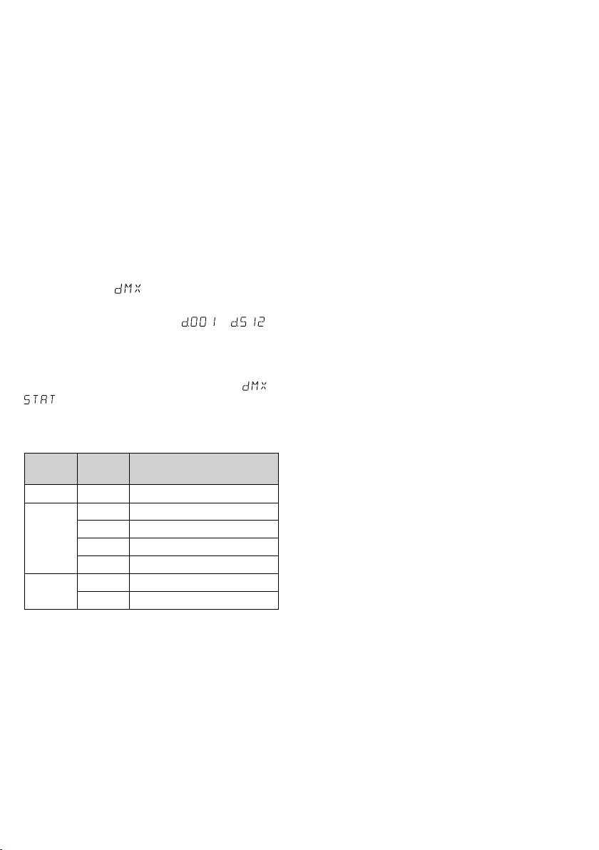
4.2.3 DMX-Kanäle und -Funktionen
DMXKanal
Abb. 6 DMX-Übersicht
DMX-
Wert
000 – 255
1
000 leicht träge Reaktion
2
001 – 250
251 – 255 sofortige Reaktion
000 – 010 Stroboskop aus
3
011 – 255
Reaktion sehr träge schnell
Stroboskop langsam schnell
Funktion
Helligkeit 0 % 100 %
Reaktion der LEDs
5 Reinigung des Geräts
Die Scheibe vor der LED sollte je nach Verschmutzung in regelmäßigen Abständen gereinigt werden. Nur dann kann das Licht in maximaler Helligkeit abgestrahlt werden. Zum Säubern den
Netzstecker aus der Steckdose ziehen. Nur ein
weiches, sauberes Tuch und ein Glaseinigungsmittel verwenden.
Zum Reinigen der anderen Gehäuseteile des
PARC-100 / WS nur ein weiches, sauberes Tuch
benutzen. Auf keinen Fall eine Flüssigkeit verwenden, die könnte in das Gerät laufen und es
beschädigen.
Das wettergeschützte Gehäuse des ODC100 / WS kann auch feucht mit einem milden
Reinigungsmittel ge säubert werden.
6 Technische Daten
Datenprotokoll: . . . . . . . . . . DMX 512
Anzahl der DMX-Kanäle:
Lichtquelle:
. . . . . . . . . . . . . weiße COB-LED
Leistungsaufnahme: . . . . . 100 W
Abstrahlwinkel: . . . . . . . . 60°
Farbtemperatur: . . . . . . . . 5600 K
DMX-Anschlüsse:
Pinbelegung: . . . . . . . . . . Pin 1 = Masse
Stromversorgung:
Leistungsaufnahme: . . . . . . max. 120 VA
Gehäuseschutzart: . . . . . . . IP 66 (nur ODC-)
Maße ohne Montagebügel: ⌀ 185 × 250 mm
Gewicht:
. . . . . . . . . . . . . . . 6,5 kg
Änderungen vorbehalten.
. . . 3
. . . . . . . . XLR, 3-polig
Pin 2 = DMX−
Pin 3 = DMX+
. . . . . . . . 230 V/ 50 Hz
Deutsch
Diese Bedienungsanleitung ist urheberrechtlich für MONACOR ® INTERNATIONAL GmbH & Co. KG geschützt. Eine
Reproduktion für eigene kommerzielle Zwecke – auch auszugsweise – ist untersagt.
7
DMX LED Spotlight
Operation of the spotlight is easy for users with
basic knowledge in DMX control. However, please
English
read the instructions carefully prior to operation
and keep them for later reference. On page 2,
you will find the spotlights ODC-100 / WS and
PARC-100 / WS together with the menu structure.
1 Applications
This LED spotlight is used for illumination, e. g. on
stage, in discotheques and function rooms. The
light source is a powerful white COB LED (COB =
chip-on-board technology): Many individual LED
chips are densely packed on a PCB to provide a
uniform light distribution.
The spotlight is designed for control via a
DMX light controller (3 DMX control channels),
but it can also be operated independently without
a controller. The ODC-100 / WS is weatherproof
(IP 66) and therefore also suited for outdoor
applications.
2 Safety Notes
The spotlight corresponds to all relevant directives
of the EU and is therefore marked with .
WARNING
The spotlight PARC-100 / WS is suitable for
•
indoor use only. Protect it against dripping
water and splash water, high air humidity and
heat (admissible ambient temperature range:
0 – 40 °C).
The spotlight ODC-100 / WS is suitable for outdoor applications (admissible ambient temperature range: −20 to +40 °C).
Immediately disconnect the mains plug from
•
the socket
1. if the spotlight or the mains cable is visibly
damaged,
2.
if a defect might have occurred after the
spotlight was dropped or suffered a similar
accident,
3. if malfunctions occur.
In any case the spotlight must be repaired by
skilled personnel.
8
The spotlight uses dangerous
mains voltage. Leave servicing to
skilled personnel; inexpert handling may result in electric shock.
Never pull the mains cable to disconnect the
•
mains plug from the socket, always seize the
plug.
For ODC-100 / WS only: A damaged mains cable
•
must be replaced by skilled personnel only.
No guarantee claims for the spotlight and no
•
liability for any resulting personal damage or
material damage will be accepted if the spotlight is used for other purposes than originally
intended, if it is not safely installed or not
correctly connected or operated, or if it is not
repaired in an expert way.
If the unit is to be put out of operation
definitively, take it to a local recycling
plant for a disposal which is not harmful
to the environment.
3 Setting the Spotlight
intoOperation
3.1 Installation
Always position the spotlight in such a way
•
to ensure sufficient air circulation during
operation. Never cover the cooling fins of the
housing.
Always keep a minimum distance of 50 cm to
•
the illuminated object.
WARNING When the spotlight is installed at
a place where people may walk or
sit under it, additionally secure it,
e. g. via a safety rope. Guide the
safety rope through the eyebolt on the rear of
the spotlight and fasten it in such a way that the
maximum falling distance of the spotlight will
not exceed 20 cm.
1. Install the spotlight via its mounting brackets,
e. g. with a stable mounting screw or a support
for lighting units (C hook) on a cross bar.
To align the spotlight, release the two locking screws of the mounting brackets. Adjust
the desired inclination of the spotlight and
fasten the screws.
2. Alternatively, set up the spotlight on its own:
Fold out the mounting brackets underneath
the spotlight and use them as a stand. Then
fasten the locking screws.
3.2 Barn doors
To reduce the light beam angle, optional barn
doors are available: PARC-100B. Fasten the barn
doors to the front of the spotlight.
3.3 Power supply
When the spotlight has been connected to the
mains, it is switched on. The display will show
the menu item most recently selected and go out
after 30 seconds. As soon as a button (MENU, UP,
DOWN or ENTER) is pressed, the display will light
up again for 30 seconds.
WARNING To prevent damage to your eyes,
never look directly into the light
source for any length of time.
Please note that fast changes in
lighting may trigger epileptic seizures with photosensitive persons
or persons with epilepsy!
3.3.1 ODC-100 / WS
Connect the plug (A) of the cable POWER IN to
the inline jack (B) of the mains cable provided.
Then fasten the nut to secure this connection.
POWER IN
Fig. 4 Mains connection ODC-100 / WS
CAUTION! The cable POWER OUT carries mains
voltage. If no further unit is connected to the cables POWER OUT and DMX OUT, always screw the
protective covers supplied onto the inline jacks.
Connect the mains plug to a socket (230 V/ 50 Hz).
Power supply of multiple ODC-100 / WS spotlights
If multiple ODC-100 / WS spotlights are used, the
units can be interconnected for power supply. For
the time being, do not yet connect the first unit
to a mains socket.
1) Use the inline jack of the cable POWER OUT
to connect the first unit to the plug (A) of the
cable POWER IN of the second unit. Proceed
in the same way to connect the second unit
to the third one etc. until all units have been
connected in a chain.
If the mains connection cables between the
spotlights are too short, use suitable extension
cables, e. g.
ODP-34AC length: 2 m or
ODP-34AC / 10 length: 10 m
A B
230 V/50 Hz
CAUTION! To reduce the risk of cable fire
caused by overload, the total current in the
connection cables must not exceed 10 A.
Therefore, do not interconnect more than
19ODC-100 / WS spotlights.
2)
On the last spotlight, screw the protective
cover supplied onto the inline jack of the cable
POWER OUT. The cable carries mains voltage!
3) Connect the mains plug of the first spotlight
to a mains socket (230 V/ 50 Hz).
3.3.2 PARC-100 / WS
For power supply, the unit is equipped with
Powercon connections.
CAUTION! Never connect or disconnect a
Powercon plug while voltage is applied. Always
make the Powercon connection before making
the mains connection. When disconnecting, always disconnect the mains connection before
disconnecting the Powercon connection.
Connect the mains jack POWER IN to a mains
socket (230 V/ 50 Hz) via the mains cable provided.
Connect the blue Powercon plug of the cable to
the mains jack, and then turn the plug clockwise
until it locks. To remove the plug, pull back the
safety latch of the plug and turn the plug counterclockwise.
Power supply of multiple PARC-100 / WS spotlights
If multiple PARC-100 / WS spotlights are used, the
jack POWER OUT of the first spotlight can be
connected to the mains jack POWER IN of the
second spotlight. For this, a mains cable with
Powercon plugs (NAC-3FCB and NAC-3FCA) is
required. Proceed in the same way to connect the
second spotlight to the third spotlight etc. until
all spotlights have been connected in a chain.
Thus, up to 19 spotlights can be interconnected.
The jack POWER OUT can also be used for power
supply of other (light effect) units.
CAUTION! To reduce the risk of fire caused by
overload, the current load of the cables and the
mains plug must not exceed 10 A.
English
9
4 Operation
The operating modes and the setting functions
are selected via a menu by means of the buttons
English
MENU, ENTER, UP and DOWN. Figure 3 on page
2 shows the selection of the modes and functions
via the menu and the indications on the display.
4.1 Independent operation
For independent operation, it is possible to set the
brightness, to activate the stroboscope function
and to set the flash rate on the spotlight.
1)
Press the button MENU repeatedly until the
display shows .
2) Press the button ENTER once or twice so that
the display shows the brightness adjusted
( … ).
3)
To set the desired brightness, press the buttons
UP and DOWN.
4)
To activate the stroboscope function, press the
button ENTER once again so that the display
shows .
5)
To set the flash rate ( … ), press
the buttons UP and DOWN.
6)
To change the brightness of the flash, press
the button ENTER to return to the menu item
for the brightness, then press the button UP
or DOWN to change the value.
7)
To deactivate the stroboscope function, set the
flash rate to .
Note: Do not use the button MENU to exit the menu
item for the brightness or the flash rate before switching
off the spotlight. If you do, the spotlight will remain dark
when it is switched on again.
4.2 Operation with a DMX controller
For operation via a DMX light controller (e. g.
DMX-1440 or DMX-510USB from IMG STAGELINE), the spotlight is equipped with three DMX
control channels. DMX stands for Digital Multi-
plex and means digital control of multiple DMX
units via a common control cable. The functions
of the channels and the DMX values can be found
in chapter 4.2.3 (fig. 6).
4.2.1 Connection
For DMX signal transmission, special cables should
be used (e. g. CDMXN-… from IMG STAGELINE).
For cable lengths exceeding 150 m or for control
of more than 32 units via a single DMX output, it
is generally recommended to insert a DMX level
matching amplifier (e. g. SR-103DMX).
1)
Connect the input DMX IN to the DMX output
of the light controller or to the DMX output of
another DMX-controlled unit.
For the spotlight ODC-100 / WS, connect
the plug (C) of the cable DMX IN to the inline
jack (D) of the supplied cable equipped with
an XLR plug. Then fasten the nut to secure
this connection.
DMX IN C
Fig. 5 DMX connection ODC-100 /WS
D
Use an extension cable to connect the XLR plug
to the DMX output of the light controller or, if
additional DMX-controlled units are used, to
the DMX output of the last DMX-controlled
unit.
2)
Connect the output DMX OUT to the DMX
input of the second DMX unit. Connect the
output of the second DMX unit to the input of
the third DMX unit etc. until all DMX-controlled
units have been connected in a chain.
If the DMX connection cables between
the units are too short when interconnecting
multiple ODC-100 / WS spotlights, use suitable
extension cables, e. g.
ODP-34DMX length: 2 m or
ODP-34DMX / 10 length: 10 m
3) To prevent interference in signal transmission,
in case of long cables or a multitude of units
connected in series, terminate the DMX output
of the last DMX unit in the chain with a 120 Ω
resistor (> 0.3 W): Connect a corresponding
terminating plug (e. g. DLT-123) to the DMX
output jack.
The easiest way to terminate the DMX
output of the ODC-100 / WS is to separate an
extension cable ODP-34DMX and to connect
10
the resistor to the pins 2 and 3 of the plug.
Connect the plug with the resistor to the inline
jack of the cable DMX OUT. If no terminating
resistor is required, screw the protective cover
provided onto the inline jack of the cable.
4.2.2 Setting the start address
For separate control of all DMX units connected
to the light controller, each unit must have its own
start address. Example: If the first DMX channel of
the spotlight is to be controlled by the light controller via DMX address 17, set the start address
on the spotlight to 17. All other DMX channels
of the spotlight will be automatically assigned to
the following addresses (i. e. the addresses 18 and
19 for the start address 17).
1)
Press the button MENU repeatedly until the
display shows .
2) Press the button ENTER. The display will show
the start address adjusted ( … ).
3) To set the desired address, press the buttons
UP and DOWN. Now the spotlight can be
operated via the light controller.
Note: When the display shows the menu item or
and DMX signals are present at the DMX input,
the dot at the right end of the display will flash.
4.2.3 DMX channels and functions
DMX
channel
Fig. 6 DMX overview
DMX
value
000 – 255
1
2
3
000 slow response
001 – 250
251 – 255 immediate response
000 – 010 stroboscope off
011 – 255
brightness 0 % 100 %
response of LEDs
response very slow fast
stroboscope slow fast
Function
5 Cleaning the Spotlight
Clean the pane in front of the LED at regular intervals depending on impurities. This is the only way
to ensure that light will be emitted at maximum
brightness. Before cleaning, disconnect the
mains plug from the socket. Only use a soft
clean cloth and a glass cleaner.
For cleaning the other parts of the housing
of the PARC-100 / WS, only use a soft clean cloth.
Never use any fluid; it may leak into the spotlight
and damage it.
The weatherproof housing of the ODC100 / WS may also be cleaned with a damp cloth
and a mild detergent.
6 Specifications
Data protocol: . . . . . . . . . . . DMX 512
Number of DMX channels:
Light source:
. . . . . . . . . . . . white COB LED
Power consumption: . . . . . 100 W
Beam angle: . . . . . . . . . . . 60°
Colour temperature: . . . . . 5600 K
DMX connections:
Pin assignment: . . . . . . . . Pin 1 = ground
Power supply:
. . . . . . . . . . . 230 V/ 50 Hz
Power consumption: . . . . . . 120 VA max.
Protection of housing: . . . . . IP 66 (ODC- only)
Dimensions w/o
mounting bracket:
Weight: . . . . . . . . . . . . . . . 6.5 kg
Subject to technical modification.
. 3
. . . . . . . XLR, 3 poles
Pin 2 = DMX−
Pin 3 = DMX+
. . . . . . . ⌀ 185 × 250 mm
English
All rights reserved by MONACOR ® INTERNATIONAL GmbH & Co. KG. No part of this instruction manual may be
reproduced in any form or by any means for any commercial use.
11

Projecteur DMX à LED
L’utilisation de l’appareil est simple et est destinée
aux utilisateurs ayant des connaissances de base
en gestion DMX. Veuillez lire cependant la pré-
Français
sente notice avec attention avant le fonctionnement et conservez-la pour pouvoir vous y reporter ultérieurement. Vous trouverez sur la page2
une représentation des modèles ODC-100 / WS
et PARC-100 / WS ainsi que la structure du menu.
1 Possibilités d’utilisation
Le projecteur LED permet de créer des effets
d’éclairage, par exemple sur scènes, en discothèques et dans des salles des fêtes. Une LED COB
blanche puissante (COB = technologie Chip on
Board) est la source de lumière: de nombreuses
puces sont placées sur un circuit imprimé de
manière très serrée pour pouvoir atteindre une
répartition régulière de la lumière.
Le projecteur est prévu pour une gestion
via un contrôleur DMX (3 canaux de commande
DMX), mais il peut également fonctionner seul
sans contrôleur. Le ODC-100 / WS est utilisable
en extérieur grâce à son boîtier étanche (IP 66).
2 Conseils d’utilisation
etdesécurité
Le projecteur répond à toutes les directives nécessaires de l’Union européenne et porte donc
le symbole .
AVERTISSEMENT Le projecteur est alimenté par
une tension dangereuse. Ne
touchez jamais l’intérieur de
l’appareil ! Risque de décharge
électrique.
Le projecteur PARC-100 / WS n’est conçu que
•
pour une utilisation en intérieur. Protégez-le de
tout type de projections d’eau, des éclaboussures, d’une humidité élevée de l’air et de la
chaleur (plage de température de fonctionnement autorisée : 0 – 40 °C).
Le projecteur ODC-100 / WS est conçu pour des
utilisations en extérieur (plage de température
de fonctionnement autorisée : −20 °C à +40 °C).
Débranchez-le immédiatement du secteur
•
lorsque :
1.
des dommages visibles apparaissent sur
l’appareil ou sur le cordon secteur,
2.
après une chute ou un cas similaire, vous
avez un doute sur l’état de l’appareil,
12
3. des dysfonctionnements apparaissent.
Dans tous les cas, les dommages doivent être
réparés par un technicien spécialisé.
Ne débranchez jamais l’appareil en tirant sur
•
le cordon secteur ; retirez toujours le cordon
secteur en tirant la fiche.
Uniquement pour le ODC-100 / WS: tout cordon
•
secteur endommagé ne doit être remplacé que
par un technicien spécialisé.
Nous déclinons toute responsabilité en cas de
•
dommages matériels ou corporels résultants si
le projecteur est utilisé dans un but autre que
celui pour lequel il a été conçu, s’il n’est pas
monté d’une manière sûre, s’il n’est pas correctement branché ou utilisé ou s’il n’est pas
réparé par une personne habilitée, en outre, la
garantie deviendrait caduque.
Lorsque le projecteur est définitivement
retiré du service, vous devez le déposer
dans une usine de recyclage adaptée pour
contribuer à son élimination non polluante.
CARTONS ET EMBALLAGE
PAPIER À TRIER
3 Fonctionnement
3.1 Montage
Placez l’appareil de telle sorte que pendant le
•
fonctionnement, une circulation suffisante d’air
soit assurée. Les ailettes de refroidissement du
boîtier ne doivent en aucun cas être obturées.
La distance avec l’objet à éclairer doit être de
•
50 cm au moins.
AVERTISSEMENT
par une élingue de sécurité. Faites passer
l’élingue via l’œillet de sécurité sur la face arrière du projecteur de telle sorte que la chute de
l’appareil ne puisse pas être supérieure à 20 cm.)
1. Fixez le projecteur via les étriers de montage,
p. ex. via une vis de montage solide ou un support pour projecteur (crochet C) à une traverse.
Pour orienter le projecteur, desserrez les
deux vis sur les étriers de montage. Réglez
l’inclinaison voulue du projecteur, puis revissez les vis.
Si le projecteur est installé à
un endroit sous lequel des
personnes peuvent se trouver,
il doit en plus être assuré, p. ex.

2. A la place, vous pouvez poser le projecteur
librement. Pour ce faire, dépliez les étriers sous
le projecteur pour qu’ils servent de support.
Revissez ensuite les vis de fixation.
3.2 Volets
Pour diminuer l’angle du faisceau lumineux, les
volets PARC-100B, disponiblesen option, se
vissent sur la face avant.
3.3 Alimentation
Le projecteur est allumé lorsque vous le reliez au
secteur. L’affichage indique le dernier point de
menu sélectionné et s’éteint après 30secondes.
Dès qu’une touche (MENU, UP, DOWN ou ENTER)
est activée, il se rallume pendant 30 s.
AVERTISSEMENT
N’oubliez pas que des changements très rapides
de lumière peuvent déclencher des crises d’épilepsie chez les personnes photosensibles et épileptiques.
3.3.1 ODC-100 / WS
Branchez la fiche mâle (A) du cordon POWER IN à
la fiche femelle (B) du cordon secteur livré. Vissez
ensemble les fiches mâle et femelle avec l’écrou.
POWER IN
Schéma 4 Branchement secteur ODC-100 / WS
ATTENTION ! Le cordon POWER OUT est conducteur de tension. Si aucun autre appareil n’est relié
aux cordons POWER OUT et DMX OUT, vissez
impérativement les caches de protection livrés
sur les fiches femelles.
Reliez ensuite le cordon secteur à une prise
230 V/ 50 Hz.
Alimentation de plusieurs ODC-100 / WS
Si plusieurs ODC-100 / WS sont utilisés, les appareils peuvent être reliés entre eux pour l’alimentation. Dans un premier temps, ne reliez pas le
premier appareil au secteur.
1) Reliez le premier appareil via la fiche femelle
du cordon POWER OUT à la fiche mâle (A) du
cordon POWER IN du deuxième appareil. Reliez
de la même manière le deuxième appareil au
Ne regardez jamais directement
la source de lumière, cela pourrait causer des troubles de la
vision.
A B
230 V/50 Hz
troisième et ainsi de suite de manière à ce que
tous les appareils soient reliés en une chaîne.
Si les câbles d’alimentation entre les appareils sont trop courts, utilisez les cordons
prolongateurs correspondants, p. ex. :
ODP-34AC longueur 2 m ou
ODP-34AC / 10 longueur 10 m
ATTENTION ! Le courant total dans les câbles
de branchement ne doit pas dépasser 10 A,
sinon une surcharge de câble peut provoquer
un incendie. C’est pourquoi, uniquement 19
appareils ODC-100 / WS au plus peuvent être
reliés ensemble.
2) Sur le dernier appareil, vissez sur la fiche femelle du cordon POWER OUT le cache de
protection livré. Le câble est conducteur de
tension !
3)
Reliez la fiche secteur du premier appareil à
une prise 230 V/ 50 Hz.
3.3.2 PARC-100/WS
Pour l’alimentation, l’appareil est doté de prises
Powercon.
ATTENTION ! Il ne faut pas brancher et débrancher une fiche Powercon sous tension. Effectuez
toujours le branchement Powercon avant la mise
sous tension. Débranchez toujours du secteur
avant de débrancher la connexion Powercon.
Reliez la prise secteur POWER IN via le cordon secteur livré à une prise 230 V/ 50 Hz. Une fois insérée
dans la prise secteur, tournez vers la droite la fiche
Powercon bleu du cordon jusqu’à enclenchement.
Pour pouvoir la retirer ultérieurement, retirez le
verrou sur la fiche et tournez-la vers la gauche.
Alimentation de plusieurs PARC-100/ WS
Si plusieurs PARC-100 / WS sont utilisés, reliez la
prise POWER OUT du premier projecteur à la prise
secteur POWER IN du deuxième projecteur. Pour
ce faire, vous avez besoin d’un cordon secteur
avec fiches Powercon (NAC-3FCB et NAC-3FCA).
Reliez le deuxième projecteur au troisième de la
même manière et ainsi de suite jusqu’à ce que
tous les projecteurs soient reliés en une chaîne. De
cette manière, on peut relier ensemble jusqu’à 19
appareils. La prise POWER OUT peut également
être utilisée pour alimenter d’autres appareils
(jeux de lumière).
ATTENTION ! Le courant dans les câbles et la
fiche secteur ne doit pas dépasser 10 A, sinon une
surcharge peut provoquer un incendie.
Français
13

4 Utilisation
La sélection du mode de fonctionnement et des
fonctions de réglage s’effectue via un menu
Français
avec les touches MENU, ENTER, UP et DOWN.
Le schéma 3 sur la page 2 présente la sélection
des modes et des fonctions via le menu et les
indications sur l’affichage.
4.1 Fonctionnement indépendant
Pour un fonctionnement indépendant, on peut,
sur le projecteur, régler la luminosité, activer la
fonction stroboscope et régler la fréquence des
éclairs.
1)
Appuyez sur la touche MENU de manière répétée jusqu’à ce que l’affichage indique .
2)
Appuyez une ou deux fois sur la touche ENTER
pour que l’affichage indique la luminosité réglée ( … ).
3) Avec les touches UP et DOWN, réglez la luminosité souhaitée.
4)
Si la fonction stroboscope doit être activée,
appuyez à nouveau sur la touche ENTER pour
que l’affichage indique .
5) Avec les touches UP et DOWN, réglez la fréquence des éclairs ( … ).
6)
Pour modifier la luminosité des éclairs, revenez
sur le point de menu pour la luminosité avec
la touche ENTER et modifiez la valeur avec la
touche UP ou DOWN.
7)
Si la fonction stroboscope doit être désactivée,
réglez la fréquence des éclairs sur .
Remarque : N’utilisez pas la touche MENU pour quitter le point de menu pour la luminosité ou pour la
fréquence des éclairs avant d’éteindre le projecteur,
sinon le projecteur reste sombre lors de la prochaine
utilisation.
4.2 Fonctionnement avec
uncontrôleurDMX
Pour une gestion via un contrôleur DMX (p. ex.
DMX-1440 ou DMX-510USB de IMG STAGELINE),
le projecteur dispose de 3 canaux de commande
DMX. DMX est l’abréviation de Digital Multiplex
et signifie la commande digitale de plusieurs appareils DMX via un câble commun de commande.
Vous trouverez les fonctions des canaux et les
valeurs DMX dans le chapitre 4.2.3 (fig. 6).
4.2.1 Branchement
Pour le branchement, il est recommandé d’utiliser
des câbles spécifiques pour la transmission de
signaux DMX (p. ex. CDMXN-… de IMG STAGELINE). Pour des longueurs de liaison à partir de
150 m ou pour la commande de plus de 32 appareils via une seule sortie DMX, il est recommandé
d’insérer un amplificateur répétiteur DMX (p. ex.
SR-103DMX).
1)
Reliez l’entrée DMX IN à la sortie DMX du
contrôleur ou d’un appareil géré par DMX.
Sur le modèle ODC-100 / WS, reliez la fiche
mâle (C) du câble DMX IN à la fiche femelle
(D) du câble livré doté de la fiche XLR mâle.
Vissez ensemble les fiches mâle et femelle avec
l’écrou.
DMX IN C
Schéma 5 Branchement DMX ODC-100 / WS
D
Reliez la fiche XLR via un cordon prolongateur
à la sortie DMX du contrôleur ou, si plusieurs
appareils gérés par DMX sont utilisés, à la sortie
DMX du dernier appareil géré par DMX.
2) Reliez la sortie DMX OUT à l’entrée DMX du
prochain appareil DMX. Reliez sa sortie à l’entrée de l’appareil DMX suivant et ainsi de suite
de manière à ce que tous les appareils gérés
par DMX forment une chaîne.
Si les câbles DMX entre les appareils sont
trop courts pour brancher ensemble plusieurs
ODC-100 / WS, utilisez les cordons prolongateurs correspondants, par exemple :
ODP-34DMX longueur 2 m ou
ODP-34DMX /10 longueur 10 m
3)
Pour éviter les perturbations lors de la transmission du signal, il convient, pour de longs câbles
ou pour une multitude d’appareils branchés
les uns derrière les autres, de terminer la sortie
DMX du dernier appareil DMX de la chaîne
avec une résistance 120 Ω (> 0,3 W): mettez
un bouchon (par exemple DLT-123) dans la
prise de sortie DMX.
Pour terminer la sortie DMX du ODC100 / WS, le plus simple est de séparer un cordon prolongateur ODP-34DMX et de brancher
la résistance aux pins 2 et 3 de la fiche. Branchez ensuite la fiche mâle avec la résistance à
14

la prise femelle du cordon DMX OUT. Si aucune
résistance terminale n’est nécessaire, vissez le
cache de protection livré sur la fiche femelle
du cordon.
4.2.2 Réglage de l’adresse de démarrage
Pour pouvoir utiliser séparément les appareils
DMX reliés au contrôleur, chaque appareil doit
avoir une adresse de démarrage propre. Si le premier canal DMX du projecteur doit être géré par
le contrôleur, par exemple via l’adresse DMX 17,
il faut régler sur le projecteur l’adresse de démarrage 17. Les autres canaux DMX du projecteur
sont automatiquement attribués aux adresses suivantes (par exemple les adresses 18 et 19 pour
l’adresse de démarrage 17).
1) Appuyez sur la touche MENU de manière répétée jusqu’à ce que l’affichage indique .
2) Appuyez sur la touche ENTER, l’affichage indique l’adresse de démarrage réglée ( …
).
3)
Avec les touches UP et DOWN, réglez l’adresse
de démarrage souhaitée. Le projecteur peut
maintenant être utilisé avec le contrôleur.
Remarque : Si l’affichage indique le point de menu
ou , le point à l’extrémité droite de l’affichage clignote lorsque des signaux DMX sont présents
à l’entrée DMX.
4.2.3 Canaux DMX et fonctions DMX
Canal
Schéma 6 Présentation DMX
Valeur
DMX
DMX
000 – 255
1
000 réaction lente
2
001 – 250
251 – 255 réaction immédiate
000 – 010 stroboscope éteint
3
011 – 255
luminosité 0 % 100 %
réaction de la LED
réaction très lente rapide
stroboscope lent rapide
Fonction
5 Nettoyage de l’appareil
La vitre devant la LED devrait être nettoyée régulièrement de toute salissure. C’est à cette condition que la lumière sera émise avec une luminosité
maximale. Pour procéder au nettoyage, dé-
branchez la fiche secteur du secteur. Utilisez
uniquement un tissu propre et doux et un nettoyant pour vitres.
Pour nettoyer les autres éléments du boîtier
du PARC-100 / WS, utilisez exclusivement un tissu
doux et propre. N’utilisez en aucun cas de liquide,
il pourrait couler dans l’appareil et causer des
dégâts.
Le boîtier étanche du ODC-100 / WS peut
également être nettoyé avec un tissu humide et
un nettoyant doux.
6 Caractéristiques techniques
Protocole données: . . . . . . DMX 512
Nombre de canaux DMX:
Source de lumière:
Consommation: . . . . . . . . 100 W
Angle de diffusion: . . . . . 60°
Température de couleur : . 5600 K
Branchements DMX:
Configuration Pin: . . . . . . Pin 1 = masse
Alimentation:
. . . . . . . . . . . 230 V/ 50 Hz
Consommation: . . . . . . . . 120 VA max.
Indice de protection boîtier: IP 66
Dimensions
sans étriers de montage:
Poids: . . . . . . . . . . . . . . . . . 6,5 kg
Tout droit de modification réservé.
. . 3
. . . . . . . LED COB blanche
. . . . . XLR, 3 pôles
Pin 2 = DMX−
Pin 3 = DMX+
(uniquement ODC-)
. . ⌀ 185 × 250 mm
Français
Notice d’utilisation protégée par le copyright de MONACOR ® INTERNATIONAL GmbH & Co. KG. Toute reproduction
même partielle à des fins commerciales est interdite.
15

Proiettore DMX con LED
L’uso dell’apparecchio è semplice ed è previsto
per utenti con conoscenze base dei comandi
Italiano
DMX. Vi preghiamo di leggere attentamente le
presenti istruzioni prima della messa in funzione e
di conservarle per un uso futuro. A pagina2 sono
illustrati i modelli ODC-100 / WS e PARC-100 / WS
nonché la struttura del menu.
1 Possibilità d’impiego
Questo proiettore con LED serve per l’illuminazione, per esempio sul palcoscenico, in discote
che o in saloni. Come fonte di luce è presente un
potente LED COB bianco (COB = tecnologia chipon-board): molti chip con LED sono sistemati strettamente su un circuito stampato. In questo modo
si ottiene una distribuzione uniforme della luce.
Il proiettore è previsto per il comando tramite
un’unità DMX di comando luce (3 canali di comando DMX). Tuttavia, può essere gestito anche
in modo autonomo, senza unità di comando.
Grazie alla sua struttura resistente alle intemperie (IP 66), l‘ODC-100 / WS può essere impiegato
anche all’esterno.
2 Avvertenze per l’uso sicuro
L’apparecchio è conforme a tutte le direttive rilevanti dell’UE e pertanto porta la sigla .
AVVERTIMENTO
Il modello PARC-100 / WS deve essere usato solo
•
all’interno di locali. Proteggerlo dall’acqua gocciolante e dagli spruzzi d’acqua, da alta umidità
dell’aria e dal calore (temperatura d’impiego
ammessa 0 a 40 °C).
Il modello ODC-100 / WS è adatto per applicazioni all’esterno (temperatura d’impiego ammessa −20 a +40 °C).
Staccare subito la spina rete se:
•
1. l’apparecchio o il cavo rete presentano dei
danni visibili;
2.
dopo una caduta o dopo eventi simili sussiste
il sospetto di un difetto;
3. l’apparecchio non funziona correttamente.
Per la riparazione rivolgersi sempre ad un’officina competente.
16
L’apparecchio è alimentato con
pericolosa tensione di rete. Non
intervenire mai personalmente
al suo interno! Esiste il pericolo
di una scarica elettrica.
Staccare il cavo rete afferrando la spina, senza
•
tirare il cavo.
Solo ODC-100 / WS: Un cavo rete, se danneg-
•
giato, deve essere sostituito solo da un laboratorio specializzato.
Nel caso d’uso improprio, di montaggio non
•
sicuro, di collegamenti sbagliati, d’impiego
scorretto o di riparazione non a regola d’arte
dell’apparecchio, non si assume nessuna responsabilità per eventuali danni consequenziali
a persone o a cose e non si assume nessuna
garanzia per l’apparecchio.
Se si desidera eliminare l’apparecchio
definitivamente, consegnarlo per lo
smaltimento ad un’istituzione locale per
il riciclaggio.
3 Messa in funzione
3.1 Montaggio
Posizionare l’apparecchio sempre in modo che
•
durante il funzionamento sia garantita una circolazione sufficiente dell’aria. Non coprire in
nessun caso le alette di raffreddamento dell’apparecchio.
La distanza dall’oggetto irradiato non dovrebbe
•
essere inferiore a 50 cm.
AVVERTIMENTO
sistema di sicurezza supplementare, p. es. per
mezzo di una fune di trattenuta. Far passare
la fune attraverso l’asola di sicurezza sul retro
dell’apparecchio e fissarla in modo tale che la caduta dell’apparecchio non possa superare i 20 cm.
1. Fissare il proiettore per mezzo delle staffe di
montaggio, p. es. con una vite robusta di montaggio o di un supporto per proiettori (gancio
a C) su una traversa.
Per orientare il proiettore, allentare le due
viti di bloccaggio delle staffe di montaggio. Impostare l’inclinazione desiderata del proiettore
e stringere nuovamente le viti.
2. In alternativa, il proiettore può essere collocato anche liberamente. Allargare le due staffe
sotto il proiettore in modo che servano come
supporto. Quindi stringere nuovamente le viti
di bloccaggio.
Se l’apparecchio viene installato in un punto sotto il quale
si possono trattenere delle
persone, occorre prevedere un

3.2 Paraluce a alette
Per ridurre l’angolo del raggio di luce, si può avvitare sul lato anteriore il paraluce a alette PARC100B disponibile come accessorio.
3.3 Alimentazione
Il proiettore si accende collegandolo con la rete. Il
display indica la voce del menu scelta per ultima
e si spegne dopo 30 s. Quando si preme un tasto
(MENU, UP, DOWN o ENTER) si riaccende per 30 s.
AVVERTIMENTO
Tenete presente che i veloci cambi di luce possono provocare attacchi d’epilessia presso persone fotosensibili o epilettici!
3.3.1 ODC-100 / WS
Inserire il connettore (A) del cavo POWER IN nella
presa (B) del cavo rete in dotazione. Con il dado
di accoppiamento unire il connettore e la presa.
POWER IN
Fig. 4 Connessione rete ODC-100 / WS
ATTENZIONE! Il cavo POWER OUT è sotto tensione. Se non è collegato nessun’altro apparecchio con i cavi POWER OUT e DMX OUT, avvitare
assolutamente sulle prese le copertura protettive
in dotazione.
Inserire la spina in una presa di rete (230 V/ 50 Hz).
Alimentazione di più ODC-100 / WS
Se si usano più ODC-100 / WS, è possibile collegare gli apparecchi per l’alimentazione. Per il momento, non collegare ancora il primo apparecchio
con una presa di rete.
1) Tramite la presa del cavo POWER OUT, collegare il primo apparecchio con il connettore (A)
del cavo POWER IN del secondo apparecchio.
Procedere nello stesso modo per il secondo e
il terzo apparecchio ecc., finché tutti gli apparecchi sono collegati formando una catena.
Se i cavi di collegamento rete fra gli apparecchi dovessero essere troppo corti, usare
prolunghe adatte, p. es.
Non guardare direttamente e
a lungo nella fonte di luce, per
escludere possibili danni agli
occhi.
A B
230 V/50 Hz
ODP-34AC lunghezza 2 m oppure
ODP-34AC / 10 lunghezza 10 m.
ATTENZIONE! La corrente globale dei cavi di
collegamento non deve superare 10 A; altrimenti, per via del sovraccarico, i cavi si possono
incendiare. Perciò non collegare fra di loro più
di 19 ODC-100 / WS.
2)
Sull’ultimo apparecchio, sulla presa del cavo
POWER OUT avvitare la copertura protettiva
in dotazione. Il cavo è sotto tensione di rete!
3) Inserire la spina del primo apparecchio in una
presa di rete (230 V/ 50 Hz).
3.3.2 PARC-100 / WS
Per l’alimentazione, l’apparecchio è equipaggiato
con contatti Powercon.
ATTENZIONE! Un connettore Powercon non
deve essere inserito o staccato sotto tensione. Perciò dapprima effettuare il collegamento Powercon, quindi il collegamento con la presa di rete,
e staccare la linea con la rete sempre prima della
connessione Powercon.
Collegare la presa POWER IN con una presa di rete
(230 V/ 50 Hz) servendosi del cavo in dotazione.
Dopo l’inserimento nella presa di rete, girare il
connettore blu Powercon del cavo a destra fino
allo scatto. Per sfilarlo successivamente, tirare
indietro la levetta di sicurezza sul connettore e
girare il connettore a sinistra.
Alimentazione di più PARC-100 / WS
Se si usano più PARC-100 / WS, la presa POWER
OUT del primo apparecchio può essere collegata con la presa rete POWER IN del secondo
apparecchio usando un cavo rete con connettori
Powercon (NAC-3FCB e NAC-3FCA). Nello stesso
modo, collegare il secondo apparecchio con il
terzo ecc. finché tutti gli apparecchi sono collegati
formando una catena. In questo modo è possibile
collegare un massimo di 19 apparecchi. La presa
POWER OUT può servire anche per l’alimentazione di altri apparecchi (per effetti di luce).
ATTENZIONE! I cavi e la spina rete non devono
essere caricati con una corrente superiore a 10 A;
altrimenti il sovraccarico può provocare un in
cendio.
Italiano
-
17

4 Funzionamento
La scelta del modo di funzionamento e delle funzioni d’impostazione avviene tramite un menu
Italiano
per mezzo dei tasti MENU, ENTER, UP e DOWN.
L’illustrazione 3 a pagina 2 dimostra come si scelgono i modi e le funzioni tramite il menu e come
saranno visualizzati dal display.
4.1 Funzionamento autonomo
Per il funzionamento autonomo, sul proiettore si
può impostare la luminosità, attivare la funzione
di stroboscopio e regolare la frequenza dei lampi.
1) Premere il tasto MENU tante volte finché il display indica .
2)
Premere una o due volte il tasto ENTER, in
modo che il display indichi la luminosità impostata ( … ).
3)
Con i tasti UP e DOWN impostare la luminosità
desiderata.
4) Se si deve attivare la funzione di stroboscopio,
premere nuovamente il tasto ENTER, in modo
che il display indichi .
5)
Con i tasti UP e DOWN impostare la frequenza
dei lampi ( … ).
6) Per modificare la luminosità dei lampi, con il
tasto ENTER ritornare alla voce del menu per
la luminosità e modificare il valore con il tasto
UP o DOWN.
7)
Se si deve disattivare la funzione stroboscopica,
portare la frequenza dei lampi a .
N. B.: Prima dello spegnimento del proiettore, per uscire
dalla voce del menu per luminosità o frequenza dei
lampi, non premere il tasto MENU. Altrimenti, il proiettore rimane buio dopo la nuova accensione.
4.2 Funzionamento con
un’unitàdicomando DMX
Per il comando tramite un’unità DMX di comando
luce (p. es. DMX-1440 o DMX-510USB di IMG
STAGELINE), il proiettore dispone di tre canali di
comando DMX. DMX è l’abbreviazione di Digi-
tal Multiplex e significa comando digitale di più
apparecchi tramite una sola linea di comando. Le
funzioni dei canali e i valori DMX sono indicati nel
capitolo 4.2.3 (fig. 6).
4.2.1 Collegamento
Per la trasmissione di segnali DMX si dovrebbero usare cavi speciali (p. es. CDMXN-… di IMG
STAGELINE). Nel caso di lunghezze oltre i 150 m o
con più di 32 apparecchi tramite una sola uscita
DMX si consiglia per principio l’impiego di un
amplificatore DMX (p. es. SR-103DMX).
1) Collegare l’ingresso DMX IN con l’uscita DMX
dell’unità di comando luce o di un altro apparecchio con comando DMX.
Nel modello ODC-100 / WS, inserire il connettore (C) del cavo DMX IN nella presa (D) del
cavo in dotazione con il connettore XLR. Con
il dado di accoppiamento unire il connettore
e la presa.
DMX IN C
Fig. 5 Connessione DMX ODC-100/WS
D
Collegare il connettore XLR con l’uscita DMX
dell’unità di comando luce usando una prolunga oppure, se si usano ulteriori apparecchi
con comando DMX, con l’uscita DMX dell’ultimo apparecchio con comando DMX.
2)
Collegare l’uscita DMX OUT con l’ingresso
DMX dell’apparecchio successivo e la sua uscita
con l’ingresso dell’apparecchio DMX seguente
ecc., finché tutti gli apparecchi con comando
DMX sono collegati formando una catena.
Se nel collegamento di più ODC-100 / WS,
i cavi DMX fra gli apparecchi dovessero essere
troppo corti, usare prolunghe adatte, p. es.
ODP-34DMX lunghezza 2 m oppure
ODP-34DMX/ 10 lunghezza 10 m.
3) Per escludere interferenze durante la trasmissione dei segnali, nel caso di linee lunghe o
di un gran numero di apparecchi collegati in
serie, l’uscita DMX dell’ultimo apparecchio
DMX della catena dovrebbe essere terminata
con una resistenza di 120 Ω (> 0,3 W): Inserire
nella presa d’uscita DMX un terminatore adatto
(p. es. DLT-123).
Per terminare l’uscita DMX di un ODC100 / WS, il modo più semplice è aprire una
prolunga ODP-34DMX e collegare la resistenza
con i pin 2 e 3 del connettore. Inserire il connettore con la resistenza nella presa del cavo DMX
OUT. Se non è richiesto nessun terminatore,
avvitare la copertura protettiva in dotazione
sulla presa del cavo.
18

4.2.2 Impostare l’indirizzo di start
Per poter comandare separatamente tutti gli apparecchi DMX collegati con l’unità per comando
luce, ogni apparecchio deve avere il suo indirizzo
di start. Se il primo canale DMX del proiettore
deve essere comandato dall’unità per comando
luce p. es. tramite l’indirizzo DMX 17, impostare
sul proiettore l’indirizzo di start 17. Tutti gli ulteriori canali DMX del proiettore saranno assegnati
automaticamente agli indirizzi successivi (p. es.
con l’indirizzo di start 17 gli indirizzi 18 e 19).
1) Premere il tasto MENU tante volte finché il display indica .
2)
Premere il tasto ENTER. Il display indica l’indirizzo di start impostato ( … ).
3) Con i tasti UP e DOWN impostare l’indirizzo
desiderato. A questo punto, il proiettore può
essere comandato dall’unità di comando luce.
N. B.: Se il display visualizza la voce del menu o
, tutto a destra lampeggia il punto quando all’in-
gresso DMX sono presenti dei segnali DMX.
4.2.3 Canali e funzioni DMX
Canale
Fig. 6 Tabella DMX
Valore
DMX
DMX
000 – 255
1
000 Reazione leggermente lenta
2
001 – 250
251 – 255 Reazione immediata
000 – 010 Stroboscopio spento
3
011 – 255
Luminosità 0 % 100 %
Reazione del LED
Reazione molto lenta veloce
Stroboscopio lento veloce
Funzione
5 Pulizia dell’apparecchio
Ad intervalli regolari, a seconda della presenza
di sporco, conviene pulire il disco davanti al LED.
Solo allora la luce può essere irradiata alla massima luminosità. Per la pulizia, staccare la spina
dalla presa. Usare solo un panno morbido, pulito
e un detergente per vetri.
Per pulire le altre parti del contenitore del
PARC-100 / WS, usare solo un panno morbido,
pulito. Non usare in nessun caso dei liquidi che
potrebbero penetrare nell’apparecchio danneggiandolo.
Il contenitore dell’ODC-100 / WS protetto contro le intemperie può essere pulito anche con un
panno inumidito e con un detergente delicato.
6 Dati tecnici
Protocollo dati: . . . . . . . . . . DMX 512
Numero dei canali DMX:
Fonte luminosa:
. . . . . . . . . LED COB bianco
Potenza assorbita: . . . . . . 100 W
Angolo d’irradiazione: . . . 60°
Temperatura cromatica: . . 5600 K
Contatti DMX: . . . . . . . . . . XLR, 3 poli
Piedinatura: . . . . . . . . . . . pin 1 = massa
Alimentazione:
. . . . . . . . . . 230 V/ 50 Hz
Potenza assorbita: . . . . . . . . max. 120 VA
Grado di protezione
del contenitore: . . . . . . . . . IP 66 (solo ODC-)
Dimensioni
senza staffe di montaggio: . ⌀ 185 × 250 mm
. . . . . . . . . . . . . . . . . . 6,5 kg
Peso:
. . . 3
pin 2 = DMX−
pin 3 = DMX+
Italiano
Con riserva di modifiche tecniche.
La MONACOR ® INTERNATIONAL GmbH & Co. KG si riserva ogni diritto di elaborazione in qualsiasi forma delle
presenti istruzioni per l’uso. La riproduzione – anche parziale – per propri scopi commerciali è vietata.
19

DMX-ledschijnwerper
De bediening van het apparaat is eenvoudig en
bedoeld voor de gebruiker met basiskennis van de
DMX-besturing. Lees de handleiding desondanks
grondig door, alvorens het apparaat in gebruik te
Nederlands
nemen, en bewaar ze voor latere raadpleging. Op
pagina2 vindt u de afbeelding van de modellen
ODC-100 / WS en PARC-100 / WS evenals de menustructuur.
1 Toepassingen
Deze led-schijnwerper wordt gebruikt voor verlichting bv. op podia, in discotheken en feest zalen.
Als lichtbron wordt een krachtige witte COB-led
gebruikt (COB = Chip-on-Board-technolo gie): Er
werden vele ledchips dicht tegen elkaar op een
printplaat aangebracht, zodat een gelijkmatige
lichtverdeling kon worden gerealiseerd.
De schijnwerper is ontworpen voor het besturen via een DMX-lichtregelaar (3 DMX-besturingskanalen), maar kan ook autonoom zonder
besturingsapparaat worden gebruikt. De ODC100 / WS is door zijn weervaste uitvoering (IP 66)
ook buiten bruikbaar.
2 Veiligheidsvoorschriften
Het apparaat is in overeenstemming met alle
relevante EU-Richtlijnen en is daarom gekenmerkt
met .
WAARSCHUWING De netspanning van de appa-
raat is levensgevaarlijk. Open
het apparaat niet. U loopt
immers het risico van een
elektrische schok.
Het model PARC-100 / WS mag alleen binnen
•
worden gebruikt. Vermijd druip- en spatwater,
uitzonderlijk warme plaatsen en plaatsen met
een hoge vochtigheid (toegestaan omgevingstemperatuurbereik 0 tot 40 °C).
Het model ODC-100 / WS is geschikt voor buiten (toegestaan omgevingstemperatuur bereik
−20tot +40 °C).
Trek onmiddellijk de netstekker uit het stop-
•
contact,
1.
wanneer het apparaat of het netsnoer zichtbaar beschadigd is,
2.
wanneer er een defect zou kunnen optreden
nadat het apparaat bijvoorbeeld is gevallen,
20
3. wanneer het apparaat slecht functioneert.
Het apparaat moet in elk geval worden hersteld
door een gekwalificeerd vakman.
Trek de stekker nooit met het snoer uit het stop-
•
contact, maar met de stekker zelf.
Alleen ODC-100 / WS: Een beschadigd netsnoer
•
mag alleen in een werkplaats worden vervangen.
In geval van ongeoorloofd of verkeerd gebruik,
•
onveilige montage, verkeerde aansluiting, foutieve bediening of van herstelling door een
niet-gekwalificeerd persoon vervalt de garantie
en de verantwoordelijkheid voor hieruit resulterende materiële of lichamelijke schade.
Wanneer het apparaat definitief uit bedrijf wordt genomen, bezorg het dan
voor milieuvriendelijke verwerking aan
een plaatselijk recyclagebedrijf.
3 Ingebruikname
3.1 Montage
Plaats het apparaat zo, dat bij het gebruik vol-
•
doende ventilatie is gegarandeerd. De koelribben van de behuizing mogen in geen geval
worden afgedekt.
De afstand tot het bestraalde voorwerp moet
•
ten minste 50 cm bedragen.
WAARSCHUWING Als het apparaat op een plek
wordt geïnstalleerd, waar personen onder kunnen komen
staan, moet het extra worden
beveiligd, bv. door een hijskabel. Steek de hijskabel door het hijsoog aan de achterzijde en
bevestig hem zo dat het apparaat niet meer dan
20 cm kan vallen.
1. Bevestig de schijnwerper via de montagebeugels, bv. met een stabiele montageschroef of
een spotlichthouder (C-haak) aan een traverse.
Voor het uitlijnen van de schijnwerper
draait u de twee bevestigingsschroeven van
de montagebeugels los. Stel de gewenste hellingshoek van de schijnwerper in en draai de
schroeven weer vast.
2. De schijnwerper kan ook vrij worden opgesteld:
spreid de montagebeugels onder de schijnwerper zodanig dat ze als steunen dienen. Haal de
bevestigingsschroeven daarna aan.

3.2 Afschermplaat
Om een lichtstraal te versmallen kunt u de als
accessoire verkrijgbare afschermplaat PARC-100B
aan de voorzijde vastschroeven.
3.3 Voedingsspanning
Door de schijnwerper op het elektriciteitsnet aan
te sluiten, is hij ingeschakeld. Op het display verschijnt het laatst geselecteerde menu-item dat
na 30seconden verdwijnt. Van zodra u op een
toets (MENU, UP, DOWN of ENTER) drukt, licht het
display weer gedurende 30seconden op.
OPGELET
Kijk niet rechtstreeks in de lichtbron
gedurende lange tijd, omdat dit de
ogen kan beschadigen.
Weet dat stroboscoopeffecten en zeer snelle
lichtwisselingen bij fotosensibele mensen en
epileptici epileptische aanvallen kunnen veroorzaken!
3.3.1 ODC-100 / WS
Plug de stekker (A) van de kabel POWER IN in
de koppeling (B) van het bijgeleverde netsnoer.
Schroef stekker en koppeling met de wartelmoer
vast.
POWER IN
Afb. 4 Netaansluiting ODC-100/WS
OPGELET! De kabel POWER OUT voert netspanning. Als er geen ander apparaat op de kabels
POWER OUT en DMX OUT is aange sloten, moet
u in elk geval de bijgeleverde beschermkappen
op de koppelingen schroeven.
Plug de netstekker in een stopcontact (230 V/
50 Hz).
Voedingsspanning voor meerdere
ODC-100 / WS-apparaten
Bij gebruik van meerdere ODC-100 / WS-apparaten kunnen de apparaten voor de voedingsspanning met elkaar worden verbonden. Sluit het
eerste apparaat in eerste instantie nog niet aan
op een stopcontact.
1) Verbind het eerste apparaat via de koppeling
van de kabel POWER OUT met de stekker (A)
van de kabel POWER IN van het tweede apparaat. Verbind het tweede apparaat op dezelfde
manier met het derde etc. tot alle apparaten
in een ketting zijn aangesloten.
A B
230 V/50 Hz
Mochten de netverbindingskabels tussen
de apparaten te kort zijn, gebruik dan geschikte verlengsnoeren, bv.:
ODP-34AC lengte 2 m of
ODP-34AC / 10 lengte 10 m.
OPGELET! De totale stroom in de aansluitkabels mag 10 A niet overschrijden, anders kan
overbelasting een kabelbrand veroorzaken.
Verbind daarom maximaal slechts 19 ODC100 / WS-apparaten met elkaar.
2)
Op het laatste apparaat schroeft u de bijgeleverde beschermkap op de koppeling
van de kabel POWER OUT. De kabel voert
net spanning!
3) Plug de netstekker van het eerste apparaat in
een stopcontact (230 V/ 50 Hz).
3.3.2 PARC-100 / WS
Voor de voedingsspanning is het apparaat uitgerust met Powercon-aansluitingen.
OPGELET! Een Powercon-stekker mag niet onder
spanning worden ingeplugd of uitgetrokken.
Breng daarom steeds eerst de Powercon-verbinding tot stand, dan de verbinding met het
stopcontact en maak de verbinding met het stopcontact steeds vóór de Powercon-verbinding los.
Verbind de netaansluiting POWER IN via het bijgeleverde netsnoer met een stopcontact (230 V/
50 Hz). Draai de blauwe Powercon-stekker van
de kabel na inpluggen in de netaansluiting naar
rechts, zodat hij vergrendelt. Om hem er later
weer uit te trekken, trekt u de vergrendeling van
de stekker naar achteren en draait u de stekker
naar links.
Voedingsspanning voor meerdere
PARC-100 / WS-apparaten
Bij gebruik van meerdere PARC-100 / WS-apparaten kunt u de jack POWER OUT van het eerste
apparaat verbinden met de netaansluiting POWER
IN van het tweede apparaat verbinden. Gebruik
hiervoor een netsnoer met Powercon-stekkers
(NAC-3FCB en NAC-3FCA). Verbind het tweede
apparaat op dezelfde manier met het derde etc.
tot alle apparaten in een ketting zijn aangesloten.
Op deze wijze mag u maximaal 19 apparaten
met elkaar verbinden. De aansluiting POWER OUT
kan ook voor de voedingsspanning van andere
(lichteffect-) apparaten worden gebruikt.
OPGELET! De kabels en de netstekker mogen
niet met meer dan 10 A worden belast, anders
kan door overbelasting brand ontstaan.
Nederlands
21

4 Bediening
Het selecteren van de bedrijfsmodus en de verschillende functies gebeurt via een menu met de
toetsen MENU, ENTER, UP en DOWN. De figuur
3 op pagina 2 toont hoe de modussen en func-
Nederlands
ties via het menu worden geselecteerd en op het
display weergegeven.
4.1 Autonoom bedrijf
Hiervoor kunt op de schijnwerper de helderheid
instellen, de stroboscoopfunctie inschakelen en
de flitsfrequentie instellen.
1) Druk enkele keren op de toets MENU tot op
het display verschijnt.
2)
Druk een of twee keer op de toets ENTER,
zodat op het display de ingestelde helderheid
verschijnt ( … ).
3)
Met de toetsen UP en DOWN stelt u de
gewenste helderheid in.
4) Als u de stroboscoopfunctie wilt inschakelen,
drukt u nogmaals op de toets ENTER, zodat
op de melding op het display verschijnt.
5)
Stel met de toetsen UP en DOWN de
flits frequentie in ( … ).
6) Om de flitshelderheid te wijzigen keert u met
de toets ENTER terug naar het menu-item voor
de helderheid; wijzig hier de waarde met de
toets UP of DOWN.
7)
Als u de stroboscoopfunctie opnieuw wilt
uitschakelen, stelt u de flitsfrequentie in op
.
Opmerking: Voordat u de schijnwerper uitschakelt, verlaat u het menu-item voor helderheid of flitsfrequentie
niet met de toets MENU. Anders blijft de schijnwerper
donker, nadat u hem opnieuw inschakelt.
4.2 Bedrijf met een DMX-regelaar
Voor de bediening via een DMX-lichtregelaar (bv.
DMX-1440 of DMX-510USB van IMG STAGELINE)
beschikt de schijnwerper over drie DMX-besturingskanalen. DMX is de afkorting van Digital
Multiplex, en staat voor digitale besturing van
meerdere apparaten via één gemeenschappelijke
besturingsleiding. De functies van de kanalen en
de DMX-waarden vindt u terug in het hoofdstuk
4.2.3 (afb. 6).
4.2.1 Aansluiting
Voor de DMX-signaaloverdracht moeten speciale kabels worden gebruikt (bv. CDMXN-... van
de serie IMG STAGELINE). Bij kabellengten vanaf
150 m of bij het sturen van meer dan 32 apparaten via een DMX-uitgang wordt in principe
aanbevolen om een DMX-ophaalversterker (bv.
SR-103DMX) tussen te schakelen.
1) Verbind de ingang DMX IN met de DMX-uitgang van de lichtregelaar of van een ander
DMX-gestuurd apparaat.
Bij het model ODC-100 / WS plugt u de
stekker (C) van de leiding DMX IN in de koppeling (D) van de bijgeleverde leiding met de
XLR-stekker. Schroef stekker en koppeling met
de wartelmoer vast.
DMX IN C
Afb. 5 DMX-aansluiting ODC-100 / WS
D
Sluit de XLR-stekker via een verlengsnoer aan
op de DMX-uitgang van de lichtregelaar of,
als er bijkomende DMX-gestuurde apparaten
worden gebruikt, op de DMX-uitgang van het
laatste DMX-gestuurde apparaat.
2) Verbind de uitgang DMX OUT met de DMXingang van het volgende DMX-apparaat.
Verbind de uitgang hiervan opnieuw met de
ingang van het nageschakelde DMX-apparaat
etc., tot alle DMX-gestuurde apparaten in een
kring zijn aangesloten.
Als bij het onderling verbinden van meerdere ODC-100 / WS-apparaten de DMX-verbindingskabels tussen de apparaten te kort zijn,
gebruik dan geschikte verlengsnoeren, bv.
ODP-34DMX lengte 2 m of
ODP-34DMX / 10 lengte 10 m.
3)
Om storingen bij de signaaloverdracht uit te
sluiten, moet u bij lange leidingen of bij een
veelvoud van aaneengesloten apparaten de
DMX-uitgang van het laatste apparaat in de
ketting afsluiten met een weerstand van 120 Ω
(> 0,3 W): steek een geschikte afsluit stekker
(bv. DLT-123) in de DMX-uitgangsbus.
De eenvoudigste manier om de DMX-uitgang van een ODC-100 / WS-apparaat af te
sluiten, is door een verlengsnoer ODP-34DMX
22

los te maken en de weerstand met de pennen 2 en 3 van de stekker te verbinden. Steek
de stekker met de weerstand in de koppeling
van de kabel DMX OUT. Als er geen afsluitweerstand nodig is, schroeft u de bijgeleverde
beschermkap op de koppeling van de kabel.
4.2.2 Startadres instellen
Om alle op de lichtregelaar aangesloten DMXapparaten afzonderlijk te kunnen bedienen, moet
elk apparaat een eigen startadres krijgen. Als het
eerste DMX-kanaal van de schijnwerper vanaf de
lichtregelaar bv. via het DMX-adres 17 gestuurd
moet worden, stel dan op de schijnwerper het
startadres 17 in. Alle andere DMX-kanalen van
de schijnwerper zijn dan auto matisch aan de
daaropvolgende adressen toegewezen (bv. bij
het startadres 17 de adressen 18 en 19).
1) Druk enkele keren op de toets MENU tot op
het display verschijnt.
2) Druk op de toets ENTER. Op het display verschijnt het ingestelde startadres ( …
).
3) Met de toetsen UP en DOWN kunt u het gewenste adres instellen. De schijnwerper kan nu
met de lichtregelaar ingesteld worden.
Opmerking: Als het menu-item of op het
display verschijnt, knippert helemaal rechts het punt, als
er DMX-signalen op de DMX-ingangen beschikbaar zijn.
4.2.3 DMX-kanalen en -functies
DMX-
kanaal
Afb. 6 DMX-Overzicht
DMX-
waarde
000 – 255
1
000 licht vertraagde reactie
2
001 – 250
251 – 255 onmiddellijke reactie
000 – 010 stroboscoop uit
3
011 – 255
helderheid 0 % 100 %
stroboscoop langzaam snel
Functie
reactie van de led
reactie erg traag snel
5 Het apparaat reinigen
De schijf vóór de led moet na verontreiniging
regelmatig worden gereinigd. Alleen dan kan
het licht met maximale helderheid worden uitgestraald. Trek de stekker uit het stopcontact
voor een reinigingsbeurt. Gebruik alleen een
zachte, schone doek en een reinigingsmiddel
voor glas.
Om de andere behuizingsonderdelen van de
PARC-100 / WS te reinigen, gebruikt u alleen een
zachte, schone doek. Gebruik in geen geval vloeistof; dit kan immers in het apparaat indringen en
schade veroorzaken.
De weerbestendige behuizing van ODC100 / WS kan ook nat met een mild reinigingsmiddel worden schoongemaakt.
6 Technische gegevens
Gegevensprotocol: . . . . . . . DMX 512
Aantal DMX-kanalen:
Lichtbron:
. . . . . . . . . . . . . . witte COB-led
Vermogensopname: . . . . . 100 W
Uitstralingshoek: . . . . . . . . 60°
Kleurtemperatuur: . . . . . . 5600 K
DMX-aansluitingen: . . . . . . XLR, 3-polig
Penconfiguratie: . . . . . . . . Pin 1 = massa
Voedingsspanning:
Vermogensopname: . . . . . . max. 120 VA
Beschermingsgraad
behuizing:
. . . . . . . . . . . . . . IP 66 (alleen ODC-)
Afmetingen zonder
montagebeugel:
Gewicht: . . . . . . . . . . . . . . . 6,5 kg
Wijzigingen voorbehouden.
. . . . . 3
Pin 2 = DMX−
Pin 3 = DMX+
. . . . . . . 230 V/ 50 Hz
. . . . . . . . . ⌀ 185 × 250 mm
Nederlands
Deze gebruiksaanwijzing is door de auteurswet be schermd eigendom van MONACOR ® INTERNATIONAL GmbH&
Co.KG. Een reproductie – ook gedeeltelijk – voor eigen commerciële doeleinden is verboden.
23

Proyector LED DMX
El funcionamiento del proyector es sencillo para
usuarios con conocimientos básicos en control
Español
DMX. De todos modos, lea atentamente las
instrucciones antes del funcionamiento y guárdelas para usos posteriores. En la página 2, podrá
encontrar los proyectores ODC-100 / WS y PARC100 / WS junto con la estructura del menú.
1 Aplicaciones
Este proyector LED sirve para iluminación, p. ej. en
escenarios, discotecas o salas de fiestas. La fuente
de luz es un LED COB blanco de gran potencia
(COB = tecnología chip on board): Muchos chips
LED individuales se colocan densamente en una
PCB para ofrecer una distribución uniforme de
la luz.
El proyector está diseñado para controlarse
mediante un controlador DMX (3 canales de control DMX), pero también puede utilizarse independientemente sin controlador. El ODC-100 / WS es
resistente a la intemperie (IP 66) y por lo tanto
está adecuado para exteriores.
2 Notas de Seguridad
El proyector cumple con todas las directivas relevantes de la UE y por lo tanto está marcado con
el símbolo .
ADVERTENCIA El proyector utiliza un voltaje de
corriente peligroso. Deje el mantenimiento para el personal técnico; el manejo inexperto puede
producir una descarga eléctrica.
El proyector PARC-100 / WS está adecuado para
•
utilizarse sólo en interiores. Protéjalo de goteos
y salpicaduras, elevada humedad del aire y calor
(temperatura ambiente admisible: 0 – 40 ºC).
El proyector ODC-100 / WS está adecuado para
exteriores (temperatura ambiente admisible:
−20 a +40 ºC).
Desconecte inmediatamente el conector de
•
corriente de la toma si:
1.
El proyector o el cable de corriente están
visiblemente dañados.
2.
El proyector ha sufrido daños después de una
caída o accidente similar.
3. No funciona correctamente.
Sólo el personal técnico puede reparar el proyector, bajo cualquier circunstancia.
24
No tire nunca del cable de corriente para des-
•
conectarlo de la toma, tire siempre del enchufe.
Sólo para el ODC-100 / WS: Un cable de co-
•
rriente dañado sólo puede repararse por el
personal cualificado.
No podrá reclamarse garantía o responsabilidad
•
alguna por cualquier daño personal o material
resultante si el proyector se utiliza para otros
fines diferentes a los originalmente concebidos,
si no se instala, no se conecta o no se utiliza
adecuadamente, o si no se repara por expertos.
Si va a poner el proyector definitivamente
fuera de servicio, llévelo a la planta de
reciclaje más cercana para que su eliminación no sea perjudicial para el
medioambiente.
3 Puesta en Marcha del Proyector
3.1 Instalación
Coloque siempre el proyector de modo que
•
exista una ventilación suficiente durante el
funcionamiento. No tape nunca las aletas de
ventilación de la carcasa.
Mantenga siempre una distancia mínima de
•
50 cm hasta el objeto iluminado.
ADVERTENCIA
con un cable de seguridad. Pase el cable de seguridad por la orejeta de la parte posterior del proyector y fíjelo de modo que la distancia máxima
de caída del proyector no supere los 20 cm.
1. Instale el proyector mediante sus soportes
de montaje, p. ej. con un tornillo de montaje
estable o un soporte para juegos de luces
(ganchoC) en una barra transversal.
Para alinear el proyector, afloje los dos
tornillos de cierre de los soportes de montaje.
Ajuste la inclinación deseada del proyector y
apriete los tornillos.
2. Como alternativa, puede ajustar el proyector
por su cuenta: Despliegue los soportes de montaje por debajo del proyector y utilícelos como
pie. Luego apriete los tornillos de cierre.
Si se instala el proyector en algún
lugar por el que la gente puede
pasear o sentarse debajo de él,
asegúrelo adicionalmente, p. ej.

3.2 Visera
Para reducir el ángulo del haz, está disponible
la visera opcional PARC-100B. Fije la visera en la
parte frontal del proyector.
3.3 Alimentación
El proyector se enciende cuando se conecta a la
corriente. El visualizador indicará el último objeto
de menú seleccionado y se apagará 30segundos
después. En cuanto se pulse un botón (MENU, UP,
DOWN o ENTER), el visualizador se iluminará de
nuevo otros 30segundos.
ADVERTENCIA
¡Tenga en cuenta que los cambios rápidos de
iluminación pueden provocar ataques epilépticos
en personas fotosensibles o con epilepsia!
3.3.1 ODC-100/WS
Conecte el conector (A) del cable POWER IN a la
toma (B) del cable de corriente entregado. Luego
fije la tuerca para asegurar esta conexión.
POWER IN
Fig. 4 Conexión de corriente del ODC-100 / WS
¡PRECAUCIÓN! El cable POWER OUT contiene
voltaje de corriente. Si no se van a conectar más
aparatos a los cables POWER OUT y DMX OUT,
asegúrese de atornillar las tapas de protección
entregadas en las tomas.
Conecte el conector de corriente a un enchufe
(230 V/ 50 Hz).
Alimentación de varios proyectores ODC-100 / WS
Si se utilizan varios proyectores ODC-100 / WS,
se pueden interconectar los aparatos para la alimentación. Por el momento, no conecte el primer
aparato a un enchufe de corriente.
1)
Utilice la toma del cable POWER OUT para
conectar el primer aparato al conector (A) del
cable POWER IN del segundo aparato. Proceda
del mismo modo para conectar el segundo
aparato al tercero, etc. hasta que todos los
aparatos estén conectados en cadena.
Si los cables de conexión DMX entre los
proyectores son demasiado cortos, utilice cables alargadores adecuados, p. ej.
Para prevenir daños oculares, no
mire nunca directamente hacia la
fuente de luz durante un tiempo
prolongado.
A B
230 V/50 Hz
ODP-34AC Longitud: 2 m
ODP-34AC/10 Longitud: 10 m
¡PRECAUCIÓN! Para reducir el riesgo de
que el cable se encienda por sobrecarga, la
corriente total de los cables de conexión no
puede exceder los 10 A. Por lo tanto, no interconecte más de 19 proyectores ODC-100 / WS.
2)
En el último proyector, atornille la tapa de protección entregada a la toma de entrada del
cable POWER OUT. ¡El cable contiene voltaje
de corriente!
3)
Conecte el conector de corriente del primer
proyector a un enchufe (230 V/ 50 Hz).
3.3.2 PARC-100 / WS
Para la alimentación, el aparato está equipado
con conexiones Powercon.
¡PRECAUCIÓN! No conecte o desconecte un
conector Powercon mientras exista algún voltaje. Haga siempre la conexión Powercon antes
de realizar la conexión a la corriente. Durante
la desconexión, desconecte siempre la conexión
de corriente antes de desconectar la conexión
Powercon.
Conecte la toma de corriente POWER IN a un
enchufe (230 V/ 50 Hz) mediante el cable de
corriente entregado. Conecte el conector Powercon azul del cable a la toma de corriente, y luego
gire el conector en sentido horario hasta que se
bloquee. Para extraer el conector, tire de la pestaña del conector y gire el conector en sentido
horario inverso.
Alimentación de varios proyectores PARC-100 / WS
Si se utilizan varios proyectores PARC-100 / WS,
la toma POWER OUT del primer proyector se
puede conectar a la toma de corriente POWER
IN del segundo proyector. Para ello, se necesita
un cable de corriente con conectores Powercon
(NAC-3FCB y NAC-3FCA). Proceda del mismo
modo para conectar el segundo proyector al
tercero, etc., hasta que todos los proyectores se
hayan conectado en una cadena. De este modo
se pueden interconectar hasta 19 proyectores.
La toma POWER OUT también se puede utilizar
para alimentar otros aparatos (juegos de luces).
¡PRECAUCIÓN! Para reducir el riesgo de que el
cable se encienda por sobrecarga, la carga de los
cables de conexión no puede exceder los 10 A.
Español
25

4 Funcionamiento
Los modos de funcionamiento y las funciones de
ajuste se seleccionan mediante un menú con los
Español
botones MENU, ENTER, UP y DOWN. La figura 3
de la página 2 muestra la selección de los modos
y funciones mediante el menú y las indicaciones
del visualizador.
4.1 Funcionamiento independiente
Se puede ajustar el brillo, activar la función estroboscopio y ajustar la velocidad de destello del
proyector para el funcionamiento independiente.
1)
Pulse el botón MENU repetidamente hasta que
en el visualizador aparezca .
2)
Pulse el botón ENTER una o dos veces para
que el visualizador indique el brillo ajustado
( … ).
3)
Para ajustar el brillo deseado, pulse los botones
UP y DOWN.
4)
Para activar la función de estroboscopio, pulse
el botón ENTER de nuevo para que el visualizador indique .
5) Para ajustar la velocidad de destello ( …
), pulse los botones UP y DOWN.
6)
Para cambiar el brillo del destello, pulse el
botón ENTER para volver al objeto de menú
para el brillo, luego pulse el botón UP o DOWN
para cambiar el valor.
7)
Para desactivar la función de estroboscopio,
ponga la velocidad de destello en .
Nota: No utilice el botón MENU para salir del objeto de
menú para brillo o velocidad de destello antes de apagar
el proyector. Si lo hace, el proyector no se iluminará
cuando lo conecte de nuevo.
4.2 Funcionamiento
conuncontrolador DMX
Para el funcionamiento mediante un controlador
DMX (p. ej. DMX-1440 o DMX-510USB de IMG
STAGELINE), el proyector está equipado con tres
canales de control DMX. DMX es la abreviatura
de Digital Multiplex y significa control digital de
varios aparatos DMX mediante un cable de control común. Las funciones de los canales y los
valores DMX pueden encontrarse en el apartado
4.2.3 (fig. 6).
4.2.1 Conexión
Para la transmisión de la señal DMX, deberían utilizarse cables especiales (p. ej. CDMXN-… de IMG
STAGELINE). Para cableados de más de 150 m o
para el control de más de 32 aparatos mediante
una única salida DMX, se recomienda insertar
un amplificador de nivel DMX adecuado (p. ej.
SR-103DMX).
1)
Conecte la entrada DMX IN a la salida de señal
DMX del controlador de luces o a la salida DMX
de otro aparato controlado por DMX.
Para el proyector ODC-100 / WS, conecte
el conector (C) del cable DMX IN a la toma (D)
del cable entregado equipado con un conector
XLR. Luego fije la tuerca para asegurar esta
conexión.
DMX IN C
Fig. 5 Conexión DMX del ODC-100 / WS
D
Utilice un cable alargador para conectar el conector XLR a la salida DMX del controlador de
luces o, si se utilizan más aparatos controlados
por DMX, a la salida DMX del último aparato
controlado por DMX.
2) Conecte la salida DMX OUT a la entrada DMX
del segundo aparato DMX. Conecte la salida
del segundo aparato DMX a la entrada del
tercer aparato DMX, etc. hasta que todos los
aparatos controlados por DMX estén conectados en cadena.
Si los cables de conexión DMX entre los
aparatos son demasiado cortos cuando se interconectan varios proyectores ODC-100 / WS,
utilice cables alargadores adecuados, p. ej.
ODP-34DMX Longitud: 2 m o
ODP-34DMX / 10 Longitud: 10 m
3)
Para evitar interferencias en la transmisión
de señal en cableados largos o para un gran
número de aparatos conectados en serie, termine la salida DMX del último aparato DMX de
la cadena con un resistor de 120 Ω (>0,3 W):
Conecte un tapón (p. ej. el DLT-123) a la salida
DMX.
El modo más sencillo para terminar la salida
DMX del ODC-100 / WS es separar un cable
alargador ODP-34DMX y conectar el resistor
a los pines 2 y 3 del conector. Conecte el
26

conector con el resistor a la toma de entrada
del cable DMX OUT. Si no se necesita ningún
resistor, atornille la tapa de protección entregada en la toma del cable.
4.2.2 Ajuste de la dirección de inicio
Para el control separado de los aparatos DMX
conectados al controlador de luces, cada aparato
debe tener su propia dirección de inicio. Ejemplo: Si hay que controlar el primer canal DMX del
proyector con el controlador de luces mediante
la dirección DMX 17, ajuste la dirección de inicio
del proyector en 17. El resto de canales DMX del
proyector se asignarán automáticamente a las
direcciones siguientes (es decir, direcciones 18 y
19 con la dirección de inicio 17).
1)
Pulse el botón MENU repetidamente hasta que
en el visualizador aparezca .
2)
Pulse el botón ENTER. El visualizador mostrará la dirección de inicio ajustada ( …
).
3)
Para ajustar la dirección deseada, pulse los
botones UP y DOWN. Ahora el proyector se
puede utilizar con el controlador de luces.
Nota: Cuando el visualizador muestra el objeto de menú
o y hay señales DMX presentes en la entrada DMX, parpadeará el punto del borde derecho
del visualizador.
4.2.3 Funciones y canales DMX
Canal
DMX
Fig. 6 Vista general DMX
Valor
DMX
000 – 255
1
000 Respuesta lenta
2
001 – 250
251 – 255 Respuesta inmediata
000 – 010 Estroboscopio apagado
3
011 – 255
Respuesta muy lenta rápida
Estroboscopio lento rápida
Función
Brillo 0 % 100 %
Respuesta del LED
5 Limpieza del Proyector
Limpie el panel frontal del LED regularmente
dependiendo de las impurezas. Este es el único
modo para asegurar que la luz se emita con su
máximo brillo. Antes de la limpieza, desco-
necte el enchufe de la toma de corriente.
Utilice sólo un paño suave y limpio y un limpiador
de cristales.
Para limpiar las otras partes de la carcasa
del PARC-100 / WS, utilice sólo un paño suave y
limpio. No utilice ningún líquido; podría penetrar
en el proyector y provocar daños.
La carcasa resistente a la intemperie del
ODC-100 / WS también se puede limpiar con un
paño húmedo y un detergente suave.
6 Especificaciones
Protocolo de datos: . . . . . . . DMX 512
Número de canales DMX:
Fuente de luz:
. . . . . . . . . . . LED COB blanco
Consumo: . . . . . . . . . . . . 100 W
Ángulo del haz: . . . . . . . . 60°
Temperatura de color: . . . . 5600 K
Conexiones DMX: . . . . . . . . XLR, 3 polos
Asignación de pin: . . . . . . Pin 1 = masa
Alimentación:
. . . . . . . . . . . 230 V/ 50 Hz
Consumo: . . . . . . . . . . . . . . 120 VA máx.
Protección de la carcasa: . . . IP 66 (sólo ODC-)
Dimensiones
sin soporte de montaje:
Peso: . . . . . . . . . . . . . . . . . . 6,5 kg
Sujeto a modificaciones técnicas.
. . 3
Pin 2 = DMX−
Pin 3 = DMX+
. . . ⌀ 185 × 250 mm
Español
Manual de instrucciones protegido por el copyright de MONACOR ® INTERNATIONAL GmbH & Co. KG. Toda
reproducción mismo parcial para fines comerciales está prohibida.
27

Reflektory diodowe DMX
Obsługa reflektora jest łatwa dla użytkowników
Polski
posiadających co najmniej podstawową wiedzę
na temat sterowania DMX. Przed rozpoczęciem
pracy z urządzeniem, prosimy zapoznać się z
instrukcją obsługi, a następnie zachować ją do
wglądu. Na stronie 2 pokazano wszystkie elementy sterujące i połączeniowe reflektorów ODC100 / WS oraz PARC-100 / WS oraz strukturę menu.
1 Zastosowanie
Niniejsze reflektory diodowe przeznaczone są do
celów oświetleniowych np. na scenie, w dyskotece lub jako element dekoracyjny. Emitują białe
światło wykorzystując technologię diodową COB
(COB = chip-on-board): wiele indywidualnych
diod zamontowanych blisko siebie na płytce PCB,
co zapewnia jednolite promieniowanie światła.
Reflektory przystosowane są do sterowa-nia
sygnałem DMX z kontrolera (3 kanały DMX), ale
mogą również pracować bez niego. Model ODC100 / WS posiada odporną na warunki atmosferyczne obudowę (IP 66), dzięki czemu może być
stosowany na zewnątrz.
2 Środki bezpieczeństwa
Reflektory spełniają wszystkie wymagania norm
UE dzięki czemu zostały oznaczone symbolem .
UWAGA
Reflektor PARC-100 / WS przeznaczony jest
•
tylko do użytku wewnątrz pomieszczeń. Należy
chronić go przed działaniem wody, dużej wilgotności powietrza oraz wysokiej temperatury
(dopuszczalny zakres 0 – 40 °C).
Reflektor ODC-100 / WS przystosowany jest do
zastosowań na zewnątrz (dopuszczalny zakres
temperatur: −20 do +40 °C).
Nie należy włączać lub natychmiast odłączyć
•
urządzenie od zasilania w przypadku
1.
jeżeli stwierdzono widoczne uszkodzenie
urządzenia lub kabla zasilającego,
2.
jeżeli urządzenie mogło ulec uszkodzeniu na
skutek upadku lub podobnego zdarzenia,
28
Urządzenia zasilane są wysokim napięciem. Wszelkie naprawy należy
zlecić specjaliście. Nieprawidłowa
obsługa może spowodować porażenie prądem elektrycznym.
3. jeżeli stwierdzono nieprawidłowe działanie.
Naprawy urządzenia może dokonywać tylko
przeszkolony personel.
Nie wolno odłączać zasilania ciągnąc za kabel,
•
należy zawsze chwytać za wtyczkę.
Dla modelu ODC-100 / WS: Wymianę uszko-
•
dzonego kabla zasilającego należy zlecić specjaliście.
Producent i dostawca nie ponoszą odpowie-
•
dzialności za wynikłe uszkodzenia sprzętu lub
obrażenia użytkownika w przypadku gdy urządzenie jest wykorzystywane w innych celach niż
to się przewiduje lub jeśli jest nieodpowiednio
zainstalowane, użytkowane lub naprawiane.
Po całkowitym zakończeniu eksploatacji,
urządzenie należy oddać do punktu recyklingu, aby nie zaśmiecać środowiska.
3 Przygotowanie do pracy
3.1 Montaż
Reflektor należy zamontować w takim miejscu,
•
aby zapewnić dostateczną cyrkulację powietrza
wokół niego. Nie wolno zasłaniać radiatorów
chłodzących na obudowie.
Zachować dystans minimum 50 cm od oświe-
•
tlanej powierzchni.
UWAGA
przed upadkiem np. wykorzystując linkę zabezpieczającą. Do zamocowania linki wykorzystać
zaczep na tylnej stronie obudowy. Długość linki
należy tak dobrać, aby w przypadku jej wykorzystania urządzenie maksymalnie spadło o 20 cm.
1. Przymocować reflektor poprzez uchwyty montażowe np. do ściany za pomocą kołków rozporowych lub na poziomej poprzeczce statywu
oświetleniowego (zaczep C).
regulatory przy uchwycie montażowym. Ustawić wybraną pozycję i dokręcić je.
2. Alternatywnie, reflektor może być ustawiany
na podłodze na uchwytach. W tym przypadku
należy mocno dokręcić śruby blokujące.
Urządzenie musi być zamontowane
w sposób bezpieczny i fachowy.
Jeśli ma pracować ponad ludźmi,
należy je dodatkowo zabezpieczyć
Dla uzyskania żądanej pozycji, poluzować

3.2 Przystawka Barn doors
W celu regulacji kąta promieniowania oraz kierunku emisji, można wykorzystać przystawkę
PARC-100B typu barn doors, dostępną jako
wyposażenie dodatkowe. Należy przykręcić ją
na przedniej stronie reflektora.
3.3 Zasilanie
Po podłączeniu zasilania, urządzenie jest włączone. Na wyświetlaczu pokazane zostanie ostatnie wybrane polecenie menu, po 30 sekundach
wyświetlacz zgaśnie. Po wciśnięcie dowolnego
przycisku (MENU, UP, DOWN lub ENTER) wyświetlacz zapali się ponownie na 30 sekund.
UWAGA
Nie należy patrzeć bezpośrednio na
diody, silne światło może uszkodzić
wzrok.
Efekt stroboskopu i szybkie zmiany światła mogą
być groźne dla osób wrażliwych na światło oraz
chorych na epilepsję!
3.3.1 ODC-100 / WS
Podłączyć wtyk (A) kabla POWER IN do gniazda
nakablowego (B) dołączonego kabla zasilającego.
Zabezpieczyć podłączenie nakrętką.
POWER IN
Rys. 4 Podłączanie zasilania ODC-100 / WS
UWAGA! Jeżeli do kabli POWER OUT oraz DMX
OUT nie są podłączane kolejne urządzenia, należy zabezpieczyć złącza dołączonymi zaślepkami.
Kabel POWER OUT znajduje się pod napięciem
sieciowym!
Podłączyć kabel zasilający do gniazdka sieciowego
(230 V/50 Hz).
Łączenie kilku reflektorów ODC-100 / WS
W przypadku używania kilku reflektorów ODC100 / WS, można je połączyć w celu wspólnego
zasilania. Nie podłączać jeszcze pierwszego
reflektora do gniazdka sieciowego.
1)
Podłączyć pierwszy reflektor, za pomocą kabla
POWER OUT do wtyku (A) kabla POWER IN kolejnego reflektora. Kolejne reflektory połączyć
analogicznie.
Jeżeli dołączone kable zasilające są za
krótkie, można zastosować odpowiedni kabel
przedłużający
A B
230 V/50 Hz
ODP-34AC długość: 2 m lub
ODP-34AC / 10 długość: 10 m
UWAGA! Całkowity prąd przepływający przez
kable połączeniowe nie może przekraczać
10 A, gdyż może to spowodować nawet zapalenie się kabla. Aby tego uniknąć, jednorazowo
można połączyć maksymalnie 19 reflektorów
ODC-100 / WS.
2)
Należy zabezpieczyć gniazdo nakablowe
POWER OUT ostatniego reflektora dołączoną
zaślepką, gdyż znajduje się ono pod napięciem!
3)
Na końcu, podłączyć wtyczkę zasilającą pierwszego reflektora do gniazdka sieciowego
(230 V/50 Hz).
3.3.2 PARC-100 / WS
Reflektor wyposażony jest w gniazdo zasilania
Powercon.
UWAGA! Dla bezpieczeństwa, niepodłączony
wtyk Powercon nie powinien znajdować się pod
napięciem. Podłączając zasilanie, należy najpierw
podłączyć wtyk Powercon do gniazda zasilania
na urządzeniu, a następnie do gniazdka sieciowego. Podczas odłączania zachować odwrotną
kolejność.
Połączyć gniazdo zasilania POWER IN z gniazdkiem sieciowym (230 V/ 50 Hz) za pomocą dołączonego kabla zasilającego. Włożyć niebieski
wtyk Powercon kabla zasilającego do gniazda,
a następnie przekręcić go w prawo aż zaskoczy.
Aby odłączyć wtyk, należy wcisnąć blokadę i przekręcić wtyk w lewo.
Łączenie kilku reflektorów PARC-100 / WS
W przypadku używania kilku reflektorów PARC100 / WS, gniazdo POWER OUT pierwszego reflektora można połączyć z gniazdem POWER
IN kolejnego reflektora. Potrzebny do tego jest
kabel zasilający z wtykami Powercon (NAC-3FCB
oraz NAC-3FCA). Kolejne reflektory połączyć
analogicznie. W ten sposób można połączyć do
19 reflektorów. Gniazdo POWER OUT może
służyć do przesyłania zasilania także do innych
urządzeń (efektów świetlnych).
UWAGA! Całkowity prąd przepływający przez
kable połączeniowe nie może przekraczać 10 A,
gdyż może to spowodować nawet zapalenie się
kabla.
Polski
29

4 Obsługa
Do poruszania się po menu i wyboru różnych
Polski
funkcji służą przyciski MENU, ENTER, UP oraz
DOWN. Na rys. 3 na str. 2 pokazano strukturę
menu sterującego.
4.1 Praca niezależna
Podczas pracy bez kontrolera, możliwa jest regulacja jasności, aktywacja funkcji stroboskopu oraz
ustawienie częstotliwości błysków.
1) Wcisnąć przycisk MENU kilka razy, aż wyświetlacz pokaże .
2)
Wcisnąć przycisk ENTER jeden lub dwa razy, aż
wyświetlacz pokaże bieżące ustawienie jasności ( … ).
3)
Ustawić żądaną jasność przyciskami UP oraz
DOWN.
4)
Aby aktywować funkcję stroboskopu, wcisnąć przycisk ENTER jeden raz, aż wyświetlacz
pokaże .
5)
Ustawić częstotliwość błysków ( …
) przyciskami UP oraz DOWN.
6)
Aby zmienić jasność błysków, wcisnąć przycisk ENTER. Wyświetlacz powróci do wskazania
jasności, następnie zmienić ustawienie przyciskami UP oraz DOWN.
7)
Aby wyłączyć funkcję stroboskopu, ustawić
częstotliwość błysków na .
Uwaga: Nie używać przycisku MENU do wychodzenia
z polecenia regulacji jasności lub częstotliwości błysków
przed wyłączeniem reflektora. Reflektor pozostanie
wówczas wygaszony po ponownym włączeniu.
4.2 Sterowanie przez kontroler DMX
DMX jest skrótem od Digital Multiplex i pozwala
na cyfrowe sterowanie wieloma urządzeniami
DMX poprzez wspólną linię. Urządzenie jest
przystosowane do sterowania przez kontroler
DMX (np. DMX-1440 lub DMX-510USB marki
IMG STAGELINE) i posiada 3 kanały DMX. Funkcje
poszczególnych kanałów DMX opisano w rozdz.
4.2.3 (rys. 6).
4.2.1 Podłączanie
Do podłączania należy wykorzystać specjalny
kabel do dużej przepływności danych (np. kabel
serii CDMXN marki IMG STAGELINE). Jeżeli
długość przewodu przekracza 150 m lub połączone są więcej niż 32 urządzenia, zalecane
jest podłączenie wzmacniacza sygnału DMX
(np. SR-103DMX).
1)
Połączyć wejście DMX IN z wyjściem DMX
kontrolera lub innego urządzenia sterowanego
sygnałem DMX.
Przy podłączaniu reflektora ODC-100 / WS,
podłączyć wtyk (C) kabla DMX IN do gniazda
nakablowego (D) dołączonego kabla z wtykiem
XLR. Zabezpieczyć połączenie nakrętką.
DMX IN C
Rys. 5 Podłączanie DMX reflektora ODC-100 / WS
D
Podłączyć wtyk XLR, za pomocą kabla przedłużającego, do wyjścia kontrolera DMX, lub innego urządzenia sterowanego sygnałem DMX.
2) Podłączyć wyjście DMX OUT do wejścia DMX
następnego urządzenia sterowanego sygnałem
DMX. Kolejne urządzenia podłączać analogicznie.
Jeżeli dołączone kable DMX są za krótkie
do połączenia kilku reflektorów ODC-100 / WS,
można zastosować kabel przedłużający
ODP-34DMX długość: 2 m lub
ODP-34DMX / 10 długość: 10 m
3) Aby zapobiec powstawaniu zakłóceń, zwłaszcza w przypadku długich linii sterujących, na
wyjście DMX ostatniego z podłączonych reflektorów podłączyć opornik 120 Ω (> 0,3 W).
Można wykorzystać do tego celu gotowy wtyk
terminujący (np. DLT-123 marki).
Najprostszym sposobem jest na podłączenie rezystora terminującego do reflektora ODC100 / WS jest rozebranie kabla ODP-34DMX i
podłączenie rezystora do pinów 2 i 3 we
wtyku. Następnie, należy podłączyć kabel do
gniazda nakablowego DMX OUT. Jeżeli podłączenie rezystora terminującego nie jest konieczne, zabezpieczyć gniazdo nakablowe
dołączoną zaślepką.
30

4.2.2 Ustawianie adresu startowego
Podczas pracy z kontrolerem, należy ustawić adres
startowy DMX pierwszego kanału. Jeżeli np. adres
17 kontrolera DMX jest przewidziany do sterowania funkcją pierwszego kanału, należy ustawić
adres 17 na reflektorze. Pozostałym funkcjom
reflektora zostaną przypisane automatycznie kolejne adresy (w tym przypadku 18 i 19).
1) Wcisnąć przycisk MENU kilka razy, aż wyświetlacz pokaże .
2) Wcisnąć przycisk ENTER. Wyświetlacz pokaże
ustawiony adres startowy ( … ).
3) Aby zmienić ustawienie, wcisnąć przycisk UP
lub DOWN. Reflektor może teraz być sterowany poprzez kontroler.
Uwaga: Jeżeli wyświetlacz pokazuje polecenie
lub i na wejściu DMX dostępny jest sygnał DMX,
zaczyna migać punkt na wyświetlaczu.
4.2.3 Funkcje kanałów DMX
Kanał
Wartość
DMX
Rys. 6 Przegląd kanałów DMX
DMX
000 – 255
1
000 wolna odpowiedź
2
001 – 250
251 – 255 natychmiastowa odpowiedź
000 – 010 stroboskop wył.
3
011 – 255
stroboskop wolno szybko
Funkcja
jasność 0 % 100 %
odpowiedź diod
odpowiedź bardzo
wolnae szybko
5 Czyszczenie urządzenia
Przedni panel reflektora należy czyścić regularnie,
zależnie od warunków pracy. Zapewni to uzyskanie maksymalnej jasności światła. Przed przystą
pieniem do czyszczenia należy bezwzględnie
odłączyć reflektor od zasilania. Do czyszczenia
panelu używać miękkiej ściereczki oraz środków
do czyszczenia szyb.
Do czyszczenia innych części obudowy reflektora PARC-100 / WS, używać suchej miękkiej
ściereczki. Nie używać wody ani innych płynów,
które mogłyby dostać się do wnętrza i spowodować uszkodzenie urządzenia.
Do czyszczenia wodoodpornej obudowy reflektora ODC-100 / WS używać miękkiej ściereczki
oraz łagodnych detergentów.
6 Specyfikacja
Protokół danych: . . . . . . . . . DMX 512
Liczba kanałów DMX:
Źródło światła:
Pobór mocy: . . . . . . . . . . . 100 W
Kąt promieniowania: . . . . 60°
Temperatura barwy: . . . . . 5600 K
Złącza DMX: . . . . . . . . . . . . XLR, 3-pinowy
Konfiguracja pinów: . . . . . Pin 1 = masa
Zasilanie:
. . . . . . . . . . . . . . . 230 V/ 50 Hz
Pobór mocy: . . . . . . . . . . . . 120 VA max
Szczelność obudowy: . . . . . IP 66 (model ODC-)
Wymiary bez uchwytów: . . . ⌀ 185 × 250 mm
Waga: . . . . . . . . . . . . . . . . . 6,5 kg
. . . . . 3
. . . . . . . . . . białe diody COB
Pin 2 = DMX−
Pin 3 = DMX+
Polski
-
Z zastrzeżeniem możliwość zmian.
Instrukcje obsługi są chronione prawem copyright for MONACOR ® INTERNATIONAL GmbH & Co. KG. Przetwarzanie
całości lub części instrukcji dla osobistych korzyści finansowych jest zabronione.
31

Læs nedenstående sikkerhedsoplysninger grundigt igennem før ibrugtagning af enheden. Bortset fra sikkerhedsoplysningerne henvises til den
Dansk
engelske tekst.
Vigtige sikkerhedsoplysninger
Denne enhed overholder alle relevante EU-direktiver og er som følge deraf mærket .
ADVARSEL
ADVARSEL
PARC-100 / WS er kun egnet til indendørs brug.
•
Beskyt den mod alle former for væsker, høj luft
fugtighed og høj varme (tilladt omgivelsestemperatur: 0 – 40 °C).
ODC-100 / WS er egnet til udendørs brug (tilladt
omgivelsestemperatur: −20 to +40 °C).
Tag straks stikket ud af stikkontakten i følgende
•
tilfælde:
1.
hvis der er synlig skade på enheden eller
netkablet,
2.
hvis der kan være opstået skade, efter at
enheden er tabt eller lignende,
3. hvis der forekommer fejlfunktion.
Enheden skal altid repareres af autoriseret personel.
Tag aldrig netstikket ud af stikkontakten ved at
•
trække i kablet, tag fat i selve stikket.
Kun for ODC-100 / WS: Er der skader på strøm-
•
kablet, skal dette straks udbedres inden lampen
tages i brug.
Til rengøring af huset må kun benyttes en tør,
•
blød klud; der må under ingen omstændigheder
benyttes kemikalier eller vand. Til rengøring
Enheden benytter livsfarlig netspænding. Udfør aldrig nogen
form for modifikationer på produktet og indfør aldrig genstande
i ventilationshullerne, da du dermed risikere at få elektrisk stød.
Kig aldrig direkte ind i lampens
LED; dette kan medføre skader
på øjnene.
Hurtige farveskift kan udløse epileptiske anfald hos personer der
fotosensitive eller lider af epilepsi!
af linsen kan der benyttes almindelig vindues- / skærmrens.
Det vejrbestandige chassis på ODC-100 / WS
rengøres med en fugtig klude, evt. med lidt
rengøringsmiddel.
Hvis enheden benyttes til andre formål, end den
•
oprindeligt er beregnet til, hvis den monteres
eller betjenes forkert, eller hvis den ikke repareres af uautoriseret personel, omfattes eventuelle
skader ikke af garantien.
Hvis enheden skal tages ud af drift for
bestandigt, skal den bringes til en lokal
genbrugsstation for bortskaffelse.
Montering
Placér altid enheden så der er rigeligt med ven-
•
tilation omkring denne.
Hold en afstand på mindst 50 cm til belyste
•
objekter.
ADVARSEL
Hvis enheden installeres på et
sted hvor personer kan bevæge
sig eller sidde under den, skal den
yderligere sikres med f. eks. en sikkerhedswire. Før sikkerhedswiren
igennem øjet og sørg for at lyseffekten maksimalt kan falde 20 cm.
Alle rettigheder til denne brugsvejledning tilhører MONACOR ® INTERNATIONAL GmbH & Co. KG. Ingen dele af
denne vejledning må reproduceres under ingen omstændigheder til kommerciel anvendelse.
32

Läs igenom säkerhetsföreskrifterna innan enheten
tas i bruk. Ytterligare information återfinns på
övriga språk i manualen.
Säkerhetsföreskrifter
Denna enhet uppfyller alla relevanta direktiv inom
EU och har därför fått märkning.
VARNING
VARNING
Spotlighten PARC-100 / WS är endast lämplig för
•
användning inomhus. Skydda den mot droppande vatten och vattenstänk, hög luftfuktighet och värme (tillåten omgivningstemperatur:
0 – 40 °C).
Spotlighten ODC-100 / WS är lämplig för utomhus applikationer (tillåten omgivningstemperatur : −20 till +40 °C).
Tag omedelbart ur elsladden ur eluttaget om
•
något av följande fel uppstår.
1.
Om enheten eller elsladden har synliga
skador.
2. Om enheten skadats av fall eller dylikt.
3. Om andra felfunktioner uppstår.
Enheten skall alltid lagas av kunnig personal.
Drag aldrig ur kontakten genom att dra i slad-
•
den, utan ta tag i kontaktkroppen.
Endast för ODC-100 / WS: En skadade nätkabel
•
får endast ersättas av utbildad personal.
Rengör endast med en mjuk och torr trasa, an-
•
vänd aldrig kemikalier eller vatten vid rengöring.
Linsen kan rengöras med vanligt fönsterputsmedel.
Enheten använder hög spänning
internt. Gör inga modifieringar
i enheten eller stoppa föremål
i ventilhålen. Risk för elskador
föreligger.
Titta aldrig direkt in i ljuskällan.
Risk för permanent ögonskada
föreligger. Observera att snabba
ljusväxlingar kan ge upphov till
epileptiska anfall hos känsliga
personer.
Det väderbeständiga höljet till ODC-100 / WS
kan även rengöras med en fuktig trasa och ett
milt rengöringsmedel.
Inga garantianspråk för enheten och inget
•
ansvar för eventuell personlig skada eller
materiella skador accepteras om enheten
används för andra ändamål än den är avsedd,
om den inte är säkert installerad, om den inte
är korrekt ansluten eller drivs, eller om den inte
repareras på en expert sätt.
Om enheten ska tas ur drift slutgiltigt, ta
den till en lokal återvinningsanläggning
för en avyttring som inte är skadligt för
miljön.
Montering
Placera enheten så att luften kan cirkulera fritt
•
runt den.
Minimiavstånd till brännbara föremål är 50 cm.
•
VARNING Om denna laser installeras på en
plats där folk kan sitta eller gå
under, så måste den säkras med
t. ex. en vajer. Trä vajern genom
öglan och fixera vajern på så sätt
att effekten inte kan falla mer än
20 cm.
Svenska
Alla rättigheter är reserverade av MONACOR ® INTER NATIONAL GmbH & Co. KG. Ingen del av denna instruktionsmanual får eftertryckas i någon form eller på något sätt användas i kommersiellt syfte.
33

Ole hyvä ja tutustu seuraaviin ohjeisiin varmistaaksesi tuotteen turvallisen käytön. Tarvitessasi
lisätietoja tuotteen käytöstä löydät ne muun kie-
Suomi
lisistä käyttöohjeista.
Turvallisuudesta
Tämä laite täyttää kaikki siihen kohdistuvat EUdirektiivit ja sille on myönnetty hyväksyntä.
VAROITUS Tämä laite toimii vaarallisella jän-
nitteellä. Älä koskaan tee mitään
muutoksia laitteeseen taikka
asenna mitään ilmanvaihto aukkoihin, koska siitä saattaa seurata
sähköisku.
VAROITUS
Spotti PARC-100 / WS soveltuu vain sisätila-
•
käyttöön. Suojele sitä kosteudelta, vedeltä
ja kuumuudelta (sallittu ympäröivä lämpötila
0 – 40 °C).
Spotti ODC-100 / WS soveltuu ulkokäyttöön
(sallittu ympäröivä lämpötila −20 to +40 °C).
Irrota virtajohto pistorasiasta, jos
•
1.
laitteessa tai virtajohdossa on havaittava
vaurio,
2.
putoaminen tai muu vastaava vahinko on
saattanut aiheuttaa vaurion,
3. laitteessa esiintyy toimintahäiriöitä
Kaikissa näissä tapauksissa laite tulee huollattaa
valtuutetussa huollossa.
Älä koskaan irrota virtajohtoa pistorasiasta joh-
•
dosta vetämällä.
Koskien spottia ODC-100 / WS: Vaurioituneen
•
virtajohdon saa vaihtaa vain valtuutettu huoltoliike.
Älä katso suoraan valonlähteeseen, se voi vaurioittaa silmää.
Erittäin nopeat valon muutokset
saattavat laukaista epileptisen
kohtauksen henkilöillä, jotka ovat
valoherkkiä tai epileptisiä.
Käytä laitteen ulkopuoliseen puhdistamiseen
•
ainoastaan kuivaa, pehmeää kangasta. Älä
milloinkaan käytä vettä tai kemikaaleja. Linssin
puhdistamisessa voidaan käyttää markkinoilla
olevia, tähän käyttöön tarkoitettuja lasilinssinpuhdistusaineita.
ODC-100 / WS säänkestävän kotelon puhdistamiseen voi käyttää kosteaa kangasta ja
mietoa puhdistusainetta.
Laitteen takuu raukeaa, eikä valmistaja, maa-
•
hantuoja tai myyjä ota vastuuta mahdollisista
välittömistä tai välillisistä vahingoista, jos laitetta
on käytetty muuhun kuin alkuperäiseen käyttötarkoituk- seen, laitetta on taitamattomasti
käytetty tai kytketty tai jos laitetta on huollettu
muussa kuin valtuutetussa huollossa.
Kun laite poistetaan lopullisesti käytöstä,
vie se paikalliseen kierrätyskeskukseen
jälkikäsittelyä varten.
Asennus
Asenna laite aina siten, että riittävä ilmankierto
•
on varmistettu käytön aikana.
Minimi välimatkan valaistavaan kohteeseen
•
pitäisi olla 50 cm.
VAROITUS
Jos laite asennetaan paikkaan,
jonka alla ihmiset kävelevät tai
istuvat, on asennus varmistettava
turvavaijerilla. Pujota turvavaijeri
korvakkeen läpi ja kiinnitä siten,
että laitteen maksimi putoamismatka ei ylitä 20 cm.
Kaikki oikeudet pidätetään MONACOR ® INTER NATIONAL GmbH & Co. KG. Mitään tämän käyttöohjeen osaa ei
saa jäljentää miltään osin käytettäväksi mihinkään kaupallisiin tarkoituksiin.
34

35

MONACOR INTERNATIONAL GmbH & Co. KG • Zum Falsch 36 • 28307 Bremen • Germany
Copyright © by MONACOR INTERNATIONAL. All rights reserved. A-1647.99.02.05.2016
 Loading...