


MXR-4 Bestellnummer 20.0250
MXR-6 Bestellnummer 20.0280
ELECTRONICS FOR SPECIALISTS ELECTRONICS FOR SPECIALISTS ELECTRONICS FOR SPECIALISTS ELECTRONICS FOR SPECIALISTS ELECTRONICS FOR SPECIALISTS ELECTRONICS FOR SPECIALISTS
1 2
1
MIC/LINE MIC/LINE
LOW
ON
CUT
G
A
I
N
MINPKMAX
13
10
H
−15 dB +15
0dB
L
10
−15 dB +15
15
20
F
25
X
30
MIN MAX
40
60
P
A
N
L R
1
14 22 25
LOW
ON
CUT
G
A
I
N
MINPKMAX
15
10
H
−15 dB +15
16
0dB
L
10
−15 dB +15
15
20
F
25
X
30
MIN MAX
40
17
60
P
A
N
L R
18
3/4
USB PH. PWR
3
RL
LINE
DSP
3/4
USB
42
G
PK
A
I
N
MIN MAX
10
H
−15 dB +15
0dB
L
10
−15 dB +15
15
20
F
25
X
30
MIN MAX
40
60
P
A
N
2
3/4|USB
6
MXR-4
19 23
P
R
O
G
D
E
L
A
Y
MIN MAX
20
F
X
MIN MAX
21
R
E
T
MIN MAXL R
5
7
ON
6
3
0dB
3
10
H.
P.
48V
8
9 11 12
24
MIN MAX
MXR-4, bei dem MXR-6 sind zwei weitere Mono-Eingängskanäle vorhanden
Audio-Mischpult
Diese Kurzanleitung soll den schnellen Einstieg in die Benutzung des
Geräts ermöglichen. Sie richtet sich
Deutsch
an Benutzer mit Grundkenntnissen
in der Audiotechnik. Bitte lesen
Sie die Anleitung vor dem Betrieb
gründlich durch und heben Sie sie
für ein späteres Nachlesen auf.
2 Sicherheitshinweise
Die Geräte (Mischpult und Netzgerät)
entsprechen allen relevanten Richtlinien
der EU und tragen deshalb das
chen.
WARNUNG Das Netzgerät wird mit
lebensgefährlicher Netzspannung versorgt. Nehmen Sie deshalb niemals
selbst Eingriffe daran vor.
1 Einsatzmöglichkeiten
Dieses kompakte Mischpult lässt sich
vielfältig zum Mischen von Audiosignalen (Mikrofone, Instrumente, Geräte mit
Line-Pegel) einsetzen. Das Mischsignal
wird über die 6,3-mm-Klinkenbuchsen
M L, M R (10) und die USB-Buchse (5)
ausgegeben. Die USB-Buchse dient auch
als Eingang für Audiodaten bei der Verbindung mit einem Computer und für den
integrierten Audiospieler zum Abspielen
von MP3-, WAV- oder WMA-Dateien von
einem USB-Stick. Der Audiospieler ist
außerdem mit einem Bluetooth- Modul
aus gestattet.
Die Geräte sind nur zur Verwendung
•
im Innenbereich geeignet. Schützen Sie
sie vor Tropf- und Spritzwasser sowie
vor hoher Luftfeuchtigkeit. Der zulässigeEinsatztemperaturbereich beträgt
0 – 40 °C.
Ziehen Sie sofort das Netzgerät aus der
•
Steckdose, wenn:
1. sichtbare Schäden an einem der Ge-
2. nach einem Sturz oder Ähnlichem
Es besteht die Gefahr eines
elektrischen Schlages.
räte vorhanden sind,
der Verdacht auf einen Defekt besteht,
M L M R
10
10
0dB
10
15
20
25
30
40
60
M
3. Funktionsstörungen auftreten.
Lassen Sie die Geräte in jedem Fall in
einer Fachwerkstatt reparieren.
Verwenden Sie zum Reinigen nur ein
•
trockenes, weiches Tuch, niemals Chemikalien oder Wasser.
Werden die Geräte zweckentfremdet,
H. P.FXRET
•
nicht richtig angeschlossen / bedient
oder nicht fachgerecht repariert, kann
keine Haftung für daraus resultierende
Sach- oder Personenschäden und keine
Garantie für die Geräte übernommen
werden. Ebenso kann keine Haftung
für durch Fehlbedienung oder durch
einen Defekt entstandene Datenverluste und deren Folgeschäden übernommen werden.
26
Sollen die Geräte endgültig
aus dem Betrieb genommen werden, übergeben Sie
sie zur umweltgerechten
Entsorgung einem örtlichen
Recyclingbetrieb.
2.1 Konformität und Zulassung
Hiermit erklärt MONACOR INTERNATIONAL, dass das Bluetooth-Modul in den
Geräten MXR-4 und MXR-6 der Richtlinie
2014 / 53 / EU entspricht. Die EU-Konformitätserklärungen sind im Internet verfügbar: www.img-stageline.de
-ZeiDas Bluetooth-Modul ist für den Betrieb
in den EU- und EFTA- Staaten allgemein
zugelassen und anmelde- und gebührenfrei.
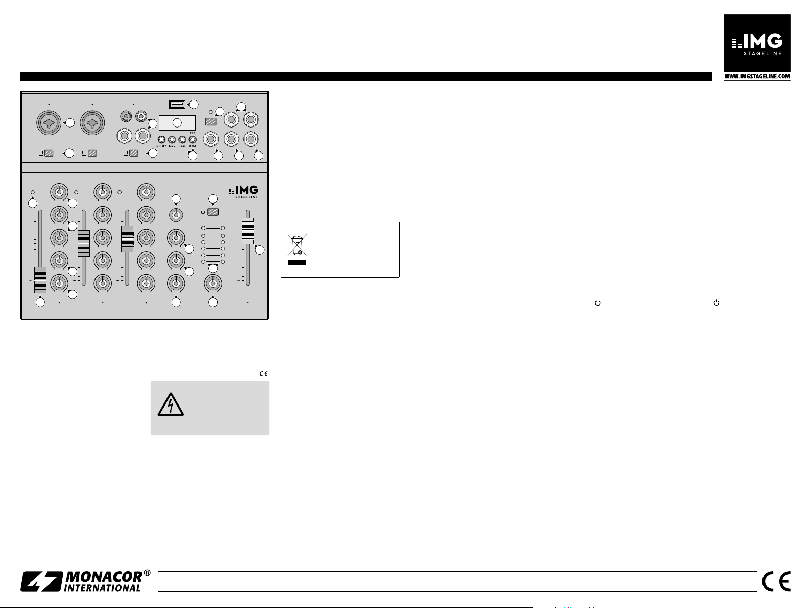
3 Übersicht
Auf der Geräterückseite befindet sich
die USB-Buchse 5 V⎓/1 A zur Stromversorgung über das beiliegende Netzgerät.
1 kombinierte Eingangsbuchse MIC /
LINE für Mikrofone (XLR) und Tonquellen mit Line-Pegel (Klinke)
2 Low-Cut-Filter : Bei gedrückter Taste
werden unerwünschte Signale mit
tiefen Frequenzen unterdrückt, z. B.
Trittschall
3 Eingang LINE des Stereokanals über
Cinch- und 6,3-mm-Klinkenbuchsen für Geräte mit Line- Pegel (z. B.
CD-Spieler, weiteres Mischpult)
4 Eingangswahltaste:
Taste ausgerastet: Eingang LINE (3)
Taste gedrückt: Eingang USB-Buchse
(5) oder Audiospieler mit BluetoothModul
5 USB-Buchse
– Ausgang digitales Mischsignal
– Eingang für Audiodaten vom Com-
puter
– Eingang für Audiodateien von
einem USB-Stick zum Abspielen
mit dem Audiospieler
6 Display für den Audiospieler; ist die
USB-Buchse(5) nicht angeschlossen,
zeigt das Display „no“ an
7 Tasten für den Audiospieler mit Blue-
tooth-Modul
REC: Start / Pause von Wieder-
II
gabe /Aufnahme
I− +I kurz drücken:
vorheriger / nächster Titel
gedrückt halten:
Lautstärke einstellen
MODE: Umschalten zwischen
– Wiedergabe (Anzeige „USb“)
– Bluetooth-Empfang („bt“)
– Aufnahme auf einen USB-
Stick („rEC“)
8 Ein- /Ausschalter PH. PWR der 48-V-
Phantomspeisung für alle XLR-Mikrofoneingänge MIC (1)
Vorsicht: Nur bei ausgeschaltetem
Mischpult betätigen, anderenfalls
können laute Schaltgeräusche auftreten.
9 Eingang RET z. B. für ein externes
Effektsignal
10 Stereo-Ausgang M L, M R für das
Mischsignal
11 Ausgang FX des Effektausspielwegs
zum Anschluss an den Eingang eines
Effektgeräts
12 Buchse H. P. (headphones) für einen
Kopfhörer
13 LED PK: Ein kurzes Aufleuchten zeigt
an, dass der maximale unverzerrte
Signalpegel erreicht ist. Leuchtet sie
länger, wird der Kanal übersteuert.
Dann den Regler GAIN (15) zurückdrehen.
14 Kanalfader für die Kanallautstärke
15 Regler GAIN für die Eingangsverstär-
kung
16 Klangregler für die Höhen (H) und
Bässe (L)
17 Regler FX zum Mischen des Kanalsig-
nals auf die interne Effekteinheit und
den AusgangFX (11)
18 Panoramaregler PAN zum Platzieren
des Mono- Signals im Stereo-Klangbild,
beim Stereo-Kanal 3 / 4 (MXR-4) bzw.
5 / 6 (MXR-6) dient er als Balanceregler
19 Drehknopf PROG zur Effektauswahl;
das Display (6) zeigt den gewählten
Effekt (01 – 16) kurz an
20 Regler DELAY für die Effektverzöge-
rungszeit
21 Regler FX zum Mischen des internen
Effektsignals auf das Ausgangssignal;
soll kein interner Effekt zugemischt
werden, den Regler auf MIN drehen
22 Regler RET (return) zum Mischen des
Signals der Buchse RET (9) auf das
Ausgangssignal, z. B. von einem externen Effektgerät
23 Ein- /Ausschalter ; beim Einschalten
zeigt das Display (6) zur Begrüßung
kurz „HI“ an
24 Ausgangspegel- und Betriebsanzeige
25 Lautstärkeregler H. P. für den Kopf-
hörer
26 Master-Fader für den Ausgangspegel
des Mischsignals an den Buchsen M L,
M R (10) und an der USB-Buchse (5)
4 Schnellstart
Zum Schutz vor lauten Störgeräuschen
vor dem Herstellen / Trennen von Verbindungen und vor dem Einschalten den
Regler H. P. (25) auf MIN drehen und den
Master-Fader (26) ganz zuziehen.
1) Die Signalquellen (Mikrofone, Instrumente usw.) an die Eingangsbuchsen
(1, 3) anschließen. Mikrofone über
XLR-Stecker anschließen, Geräte
mit Line- Pegel über Klinken- oder
Cinch-Stecker. Beim Anschluss an
die Eingangsbuchsen LINE (3) darf
die Taste (4) darunter nicht gedrückt
sein; wird die USB-Buchse (5) oder
der Audiospieler verwendet, die Taste
hineindrücken. Nur beim Einsatz von
Mikrofonen, die eine Phantomspeisung benötigen, die Taste PH. PWR. (8)
hineindrücken.
Wird ein Computer zum Abspielen
von Audiodateien oder für Aufnahmen
verwendet, diesen an die USB-Buchse
(5) anschließen.
2) Das Gerät, auf welches das Mischsignal gegeben werden soll (Verstärker,
Aktivlautsprecherbox, Aufnahmegerät), an die Ausgangsbuchsen M L, M R
(10) anschließen. Ein Kopfhörer zum
Abhören kann an die Buchse H. P. (12)
angeschlossen werden.
3) Das beiliegende Netzgerät an die USBBuchse 5 V⎓/1 A auf der Rückseite (!)
anschließen und in eine Steckdose
(230 V/ 50 Hz) stecken.
4) Zur Grundeinstellung vorerst
– die Regler GAIN (15), H, L (16) und
PAN (18) in die Mittelstellung drehen
– die Regler FX (17, 21) und RET (22)
auf MIN drehen
– die Kanalfader (14) ganz zuziehen
5) Die Signalquellen einschalten, dann
das Mischpult mit der Taste
(23) und
zuletzt das an den Ausgangsbuchsen
(10) angeschlossene Gerät. Zum Ausschalten in umgekehrter Reihenfolge
vorgehen.
6) Den Master-Fader (26) auf die Position
0 dB schieben und mit den Kanalfadern
(14) die Eingangssignale mischen.
Muss ein Kanalfader sehr weit
aufgezogen werden, die Eingangsverstärkung durch Aufdrehen des Reglers
GAIN (15) erhöhen. Leuchtet jedoch
die LED PK (13) länger auf, den Regler
GAIN entsprechend zurückdrehen. Die
LED PK darf nur bei Signalspitzen kurz
aufflackern.
7) Den Klang der Eingangssignale mit den
Reglern H und L (16) einstellen. Das
Ausgangssignal für das nachfolgende
Gerät optimal mit dem Master- Fader
(26) aussteuern. Mit dem Regler H. P.
(25) die Kopfhörerlautstärke einstellen
(nicht zu hoch, hohe Lautstärken schädigen das Gehör!).
Änderungen vorbehalten.
MONACOR INTERNATIONAL GmbH & Co. KG • Zum Falsch 36 • 28307 Bremen • Germany Copyright© by MONACOR INTERNATIONAL. All rights reserved. A-2019.99.03.05.2020
MXR-4 Order number 20.0250
MXR-6 Order number 20.0280
ELECTRONICS FOR SPECIALISTS ELECTRONICS FOR SPECIALISTS ELECTRONICS FOR SPECIALISTS ELECTRONICS FOR SPECIALISTS ELECTRONICS FOR SPECIALISTS ELECTRONICS FOR SPECIALISTS
1 2
1
MIC/LINE MIC/LINE
LOW
ON
CUT
G
A
I
N
MINPKMAX
13
10
H
−15 dB +15
0dB
L
10
−15 dB +15
15
20
F
25
X
30
MIN MAX
40
60
P
A
N
L R
1
14 22 25
LOW
ON
CUT
G
A
I
N
MINPKMAX
15
10
H
−15 dB +15
16
0dB
L
10
−15 dB +15
15
20
F
25
X
30
MIN MAX
40
17
60
P
A
N
L R
18
3/4
USB PH. PWR
3
RL
LINE
DSP
3/4
USB
42
G
PK
A
I
N
MIN MAX
10
H
−15 dB +15
0dB
L
10
−15 dB +15
15
20
F
25
X
30
MIN MAX
40
60
P
A
N
2
3/4|USB
6
MXR-4
19 23
P
R
O
G
D
E
L
A
Y
MIN MAX
20
F
X
MIN MAX
21
R
E
T
MIN MAXL R
5
7
ON
6
3
0dB
3
10
H.
P.
48V
8
9 11 12
24
MIN MAX
MXR-4; the audio mixer MXR-6 provides two additional mono input channels
Audio mixer
These brief instructions give a quick
overview of how to use the audio
English
mixer. They are intended for users
with basic knowledge of audio
technology. Please read these instructions carefully prior to operating the unit and keep them for later
reference.
2 Safety Notes
The units (mixer and power supply unit)
correspond to all relevant directives of
the EU and are therefore marked with
WARNING The power supply unit
uses dangerous mains
voltage. Leave servicing
to skilled personnel; inexpert handling may result
in electric shock.
The units are suitable for indoor use
1 Applications
This compact mixer can be used in many
ways to mix audio signals (microphones,
instruments, units with line level). The
mixed signal is output via the 6.3 mm
jacks M L, M R (10) and the USB port (5).
The USB port is also used as an input for
audio data when the mixer is connected
to a computer and for the integrated
audio player to replay MP3, WAV and
WMA files from a USB flash drive. In addition, the audio player is equipped with
a Bluetooth module.
•
only. Protect them against dripping
water, splash water and high air humidity. The admissible ambient temperature range is 0 – 40 °C.
Immediately disconnect the power
•
supply unit from the mains socket,
1. if a unit is visibly damaged,
2. if a defect might have occurred after
a unit was dropped or suffered a
similar accident,
3. if malfunctions occur.
In any case the units must be repaired
by skilled personnel.
M L M R
10
10
0dB
10
15
20
25
30
40
60
M
For cleaning only use a dry, soft cloth;
•
never use water or chemicals.
No guarantee claims for the units and
•
no liability for any resulting personal
damage or material damage will be
accepted if the units are used for other
H. P.FXRET
purposes than originally intended, if
they are not correctly connected or
operated, or if they are not repaired
in an expert way. Likewise, no liability
will be accepted for data loss caused
by a defect or operating errors and
for any consequential damage of this
data loss.
If the units are to be put out
of operation definitively, take
26
them to a local recycling
plant for a disposal which is
not harmful to the environment.
2.1 Conformity and approval
Herewith, MONACOR INTERNATIONAL
declare that the Bluetooth module in the
units MXR-4 and MXR-6 complies with
the directive 2014 / 53 / EU. The EU declarations of conformity are available on the
Internet:
www.img-stageline.com
The Bluetooth module is generally ap-
.
proved for operation in EU and EFTA
countries; it is licence-free and requires
no registration.
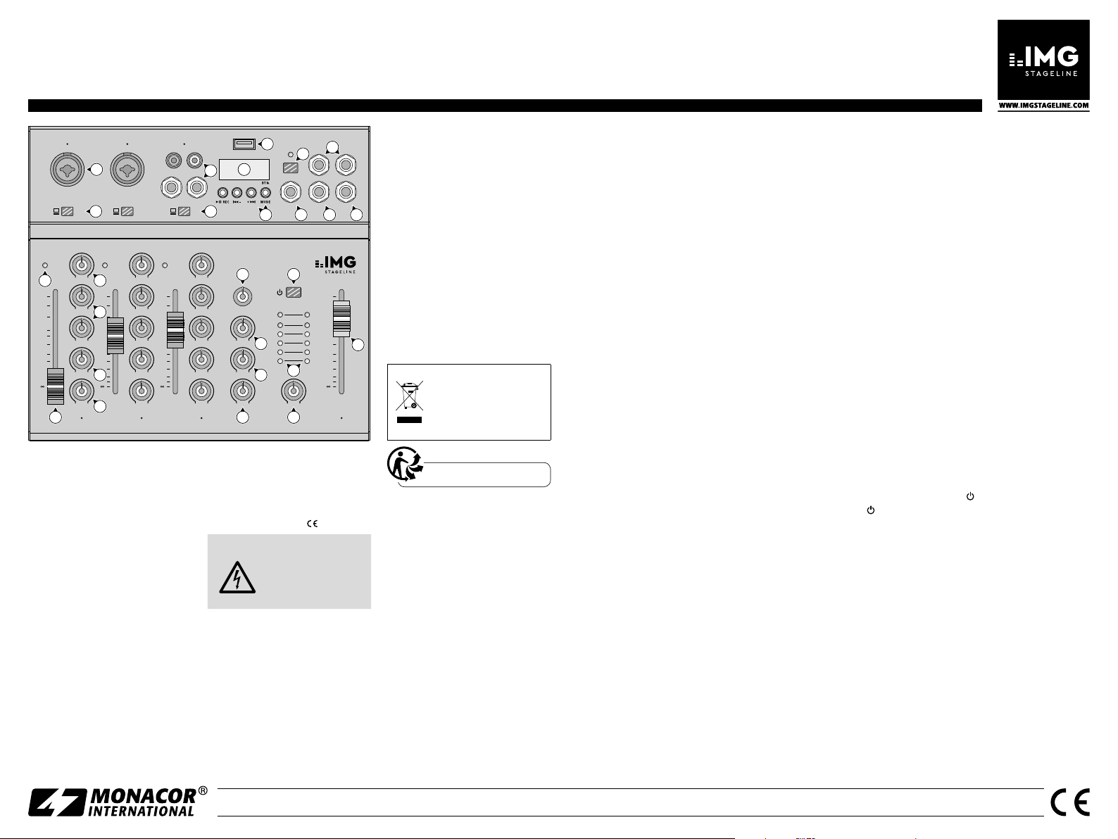
3 Overview
The USB port 5 V⎓/1 A for power supply
via the power supply unit provided is
located on the rear side of the unit.
1 Combined input jack MIC / LINE for
microphones (XLR) and audio sources
with line level (6.3 mm)
2 Low-cut filter: when the button is
pressed, undesired signals with low
frequencies, e. g. impact sound, will
be suppressed
3 Input LINE of the stereo channel via
RCA jacks and 6.3 mm jacks for units
with line level (e. g. CD player, additional mixer)
4 Input selector switch:
Button disengaged: input LINE (3)
Button engaged: input USB port (5) or
audio player with Bluetooth module
5 USB jack:
– output for mixed digital signal
– input for audio data from the com-
puter
– input for audio files from a USB
flash drive to be replayed by means
of the audio player
6 Display for the audio player; when
the USB port (5) is not connected,
“no” will be shown on the display
7 Buttons for the audio player with
Bluetooth module
II REC:
start / pause for replay / recording
Briefly press I− +I :
previous / next title
Keep I− +I pressed:
to adjust the volume
MODE: switch between
– replay (indication: “USb”)
– Bluetooth reception (“bt”)
– recording on a USB flash
drive (“rEC”)
8 On / Off switch PH. PWR of the 48 V
phantom power supply for all XLR
microphone inputs MIC(1)
Caution: Only use the switch when
the mixer is switched off; otherwise,
there may be loud switching noise.
9 Input RET, e. g. for an external effect
signal
10 Stereo output M L, M R for the mixed
signal
11 Output FX of the effect send way for
connection to the input of an effect
unit
12 Jack H. P. for headphones
13 LED indicator PK: will light up briefly
when the maximum undistorted signal level has been reached. If it lights
up for a longer time, the channel is
overloaded; in this case, turn back the
control GAIN (15).
14 Channel fader for the volume of the
channel
15 Control GAIN for the input gain
16 Sound control for the high frequen-
cies (H) and low frequencies (L)
17 Control FX to add the channel signal
to the internal effect unit and to the
output FX (11)
18 Panorama control PAN to place the
mono signal in the stereo sound,
for the stereo channel 3 / 4 (MXR-4) or
5 / 6 (MXR6), the control is used as a
balance control
19 Rotary knob PROG for effect selec-
tion; the display (6) will briefly indicate the effect selected (01 – 16)
20 Control DELAY for the effect delay
time
21 Control FX to add the internal effect
signal to the output signal; set the
control to MIN when no internal effect is to be added
22 Control RET (return) to add the sig-
nal of the jack RET (9) to the output
signal, e. g. of an external effect unit
23 Power switch ; when the mixer is
switched on, the display will briefly
show the welcome message “HI”
24 Output level indicator and power
indicator
25 Volume control H. P. for the head-
phones
26 Master fader for the output level of
the mixed signal at the jacks M L,
M R(10) and at the USB port (5)
4 Quick Start
To avoid loud interfering noise, set the
control H. P.(25) to MIN and close the
master fader (26) prior to connection /
disconnection and switch-on.
1) Connect the signal sources (microphones, instruments, etc.) to the input
jacks (1, 3). Connect the microphones
by means of XLR plugs and units with
line level by means of 6.3 mm plugs
or RCA plugs. When connecting signal
sources to the input jacks LINE (3),
make sure that the button (4) beneath
the input jacks is not pressed; when
the USB port (5) or the audio player
is used, press the button. Press the
button PH. PWR (8) only when using
microphones that require phantom
power supply.
When a computer is used to replay
audio files or for recordings, connect
the computer to the USB port (5).
2) Connect the unit to which the mixed
signal is to be sent (amplifier, active
speaker system, recorder) to the output jacks M L, M R (10). Headphones to
monitor the signal can be connected to
the jack H. P. (12).
3) Connect the power supply unit provided to the USB port 5 V⎓/1 A (located on the rear side of the unit!) and
to a mains socket (230 V/ 50 Hz).
4) To make the basic adjustments, first
– set the controls GAIN (15), H, L (16)
and PAN (18) to mid-position
– set the controls FX (17, 21) and
RET(22) to MIN
– close the channel faders (14)
5) Switch on the signal sources, then
switch on the mixer by means of
the button
(23) and finally switch
on the unit connected to the output
jacks(10). To switch off, proceed in the
reverse order.
6) Move the master fader (26) to the position 0 dB; use the channels faders (14)
to mix the input signals.
If a channel fader must be advanced almost to its maximum, turn
the control GAIN (15) to the right to
increase the input gain. If the LED indicator PK (13) lights up for a longer
period of time, turn back the control
accordingly. The LED indicator PK may
only briefly flicker at signal peaks.
7) Use the controls H and L (16) to adjust
the sound of the input signals. Use the
master fader (26) to adjust the output
signal for the subsequent unit to an
optimum level. Use the control H. P.
(25) to adjust the volume of the headphones (make sure that the volume is
not too high; high volumes may damage your hearing!).
Subject to technical modification.
MONACOR INTERNATIONAL GmbH & Co. KG • Zum Falsch 36 • 28307 Bremen • Germany Copyright© by MONACOR INTERNATIONAL. All rights reserved. A-2019.99.03.05.2020
MXR-4 Référence num. 20.0250
MXR-6 Référence num. 20.0280
ELECTRONICS FOR SPECIALISTS ELECTRONICS FOR SPECIALISTS ELECTRONICS FOR SPECIALISTS ELECTRONICS FOR SPECIALISTS ELECTRONICS FOR SPECIALISTS ELECTRONICS FOR SPECIALISTS
1 2
1
MIC/LINE MIC/LINE
LOW
ON
CUT
G
A
I
N
MINPKMAX
13
10
H
−15 dB +15
0dB
L
10
−15 dB +15
15
20
F
25
X
30
MIN MAX
40
60
P
A
N
L R
1
14 22 25
LOW
ON
CUT
G
A
I
N
MINPKMAX
15
10
H
−15 dB +15
16
0dB
L
10
−15 dB +15
15
20
F
25
X
30
MIN MAX
40
17
60
P
A
N
L R
18
3/4
USB PH. PWR
3
RL
LINE
DSP
3/4
USB
42
G
PK
A
I
N
MIN MAX
10
H
−15 dB +15
0dB
L
10
−15 dB +15
15
20
F
25
X
30
MIN MAX
40
60
P
A
N
2
3/4|USB
6
MXR-4
19 23
P
R
O
G
D
E
L
A
Y
MIN MAX
20
F
X
MIN MAX
21
R
E
T
MIN MAXL R
5
7
ON
6
3
0dB
3
10
H.
P.
M L M R
48V
8
9 11 12
24
MIN MAX
MXR-4 ; la table MXR-6 possède deux canaux d’entrée mono supplémentaires
Table de mixage audio
Ces brèves instructions donnent
une vue d‘ensemble rapide sur la
façon d‘utiliser la table de mixage
Français
audio. Cette notice s’adresse aux
utilisateurs avec des connaissances
de base en audio. Veuillez lire la
présente notice avec attention avant
le fonctionnement et conservez-la
pour pouvoir vous y reporter ultérieurement.
1 Possibilités d’utilisation
Cette table de mixage compacte peut
être utilisée de plusieurs manières pour
mixer des signaux audio (microphones,
instruments, appareils avec niveau ligne).
Le signal de mixage est pris via les prises
jack 6,35 M L, M R (10) et le port USB (5).
Le port USB sert aussi d’entrée pour des
données audio lorsque la table est reliée
à un ordinateur et pour le lecteur audio
intégré pour lire des fichiers MP3, WAV
ou WMA d’une clé USB. Le lecteur audio
est en plus doté d’un module Bluetooth.
2 Conseils de sécurité
Les appareils (table de mixage et bloc
secteur) répondent à toutes les directives
nécessaires de l’Union Européenne et
portent donc le symbole
AVERTISSE-
MENT
Les appareils ne sont conçus que
•
pour une utilisation en intérieur. Protégez-les des éclaboussures, de tout
type de projections d‘eau et d’une humidité élevée de l‘air. La température
ambiante admissible est de 0 – 40 °C.
Débranchez le bloc secteur immédiate-
•
ment dans les cas suivants :
1. un des appareils présente des dom-
2. après une chute ou accident simi-
Le bloc secteur est alimenté par une tension
dangereuse. Ne touchez
jamais l‘intérieur de
l‘appareil. Il y a risque de
décharge électrique.
mages visibles.
laire, vous avez un doute sur l‘état
de l‘appareil.
3. des dysfonctionnements apparaissent.
10
Dans tous les cas, les dommages
doivent être réparés par un technicien
spécialisé.
Pour le nettoyage, utilisez un chiffon
•
sec et doux, en aucun cas de produits
H. P.FXRET
chimiques ou d’eau.
Nous déclinons toute responsabilité en
•
cas de dommages corporels ou matériels résultants si les appareils sont utilisés dans un but autre que celui pour
lequel ils ont été conçus, s’ils ne sont
pas correctement branchés ou utilisés
10
0dB
10
15
26
20
25
30
40
60
ou s’ils ne sont pas réparés par une personne habilitée ; en outre, la garantie
deviendrait caduque. De même, notre
responsabilité ne saurait être engagée
en cas de pertes de données causées
par une mauvaise manipulation ou par
un défaut et leurs conséquences.
Lorsque les appareils sont définitivement retirés du service,
vous devez les déposer dans
M
une usine de recyclage de
proximité pour contribuer à
leur élimination non polluante.
3 Entrée LINE du canal stéréo via prises
RCA et jack 6,35 pour appareils avec
niveau ligne (par exemple lecteur CD,
autre table de mixage)
4 Sélecteur d’entrée
Touche non enfoncée : entrée LINE (3)
Touche enfoncée : entrée port USB (5)
ou lecteur audio avec module Bluetooth
5 Port USB
– sortie signal digital de mixage
– entrée pour données audio d’un
ordinateur
– entrée pour fichiers audio d’une clé
USB pour lire avec le lecteur audio
6 Affichage pour le lecteur audio ; si le
port USB (5) n’est pas branché, l’affichage indique «no»
7 Touches pour le lecteur audio avec
module Bluetooth
REC : Start / Pause (marche /arrêt)
II
pour lecteur / enregistre-
ment
appuyez brièvement :
I− +I
titre précédent / suivant
maintenez enfoncée :
CARTONS ET EMBALLAGE
PAPIER À TRIER
MODE : commutation entre
2.1 Conformité et autorisation
.
Par la présente MONACOR INTERNATIONAL déclare que le module Bluetooth dans
les appareils MXR-4 et MXR-6 répond à
la directive 2014 / 53 / UE. Les déclarations
de conformité sont disponibles sur le site:
www.img-stageline.com
Le module Bluetooth est autorisé dans les
pays de l’U.E. et les pays de l’A.E.L.E. et
n’est pas soumis à déclaration ou taxe.
8 Interrupteur marche / arrêt PH.PWR
de l’alimentation fantôme 48 V pour
toutes les entrées micro XLR MIC (1)
Attention : ne doit être activé que si
la table de mixage est éteinte, sinon,
des bruits forts de commutation
peuvent apparaître.
réglage du volume
– Lecture (affichage «USb»)
– Réception Bluetooth («bt»)
– Enregistrement sur une clé
USB («rEC»)
9 Entrée RET par exemple pour un
3 Présentation
Le port USB 5 V⎓/1 A pour l’alimentation
via le bloc secteur livré se trouve sur la
face arrière.
1 Prise d’entrée combo MIC / LINE pour
microphones (XLR) et sources audio
avec niveau ligne (jack 6,35)
2 Filtre Low-Cut : lorsque la touche est
enfoncée, les signaux non souhaités
avec des fréquences graves sont éliminés, par exemple bruits de pas
signal externe d’effet
10 Sortie stéréo M L, M R pour le signal
de mixage
11 Sortie FX de la voie d’effet pour bran-
cher à l’entrée d’un appareil à effets
12 Prise H. P. (headphones) pour un
casque
13 LED PK : si elle brille brièvement, le
niveau de signal maximal non distordu est atteint. Si elle brille plus
longtemps, le canal est en surcharge.
Tournez alors le réglage GAIN (15)
vers la gauche.
14 Fader de canaux pour le volume des
canaux
15 Réglage GAIN pour l’amplification
d’entrée
16 Egaliseur pour les aigus (H) et les
graves (L)
17 Réglage FX pour mixer le signal d’un
canal sur l’unité interne d’effets et la
sortie FX (11)
18 Réglage de panoramique PAN pour
placer le signal mono dans l’image
sonore stéréo,
sur le canal stéréo 3 / 4 (MXR-4) ou
5 / 6 (MXR-6), il sert de réglage de
balance
19 Bouton rotatif PROG pour sélection-
ner l’effet ; l’affichage (6) indique brièvement l’effet sélectionné (01 – 16)
20 Réglage DELAY pour la durée de tem-
porisation de l’effet
21 Réglage FX pour mixer le signal in-
terne d’effet sur le signal de sortie; si
aucun effet interne ne doit être mixé,
tournez le réglage sur MIN
22 Réglage RET (return) pour mixer le
signal de la prise RET (9) sur le signal
de sortie, par exemple d’un appareil
externe d’effet
23 Interrupteur marche / arrêt ;
lors de l’allumage, l’affichage (6) indique «HI» comme message d’accueil
24 Témoin du niveau de sortie et de
fonctionnement
25 Réglage de volume H. P. pour le casque
26 Fader Master pour le niveau de sortie
du signal de mixage aux prises M L,
M R (10) et au port USB (5)
4 Démarrage rapide
Pour éviter tout bruit fort, avant d’établir les branchements et de les défaire
et avant d’allumer la table de mixage,
tournez le réglage H. P. (25) sur MIN et
poussez le fader Master (26) entièrement
vers le bas.
1) Reliez les sources de signal (microphones, instruments …) aux prises
d’entrée (1, 3). Reliez les microphones
via les fiches XLR, les appareils avec
niveau ligne via les fiches 6,35 ou
RCA. Si vous utilisez les prises d’entrée LINE(3), la touche (4) située en
dessous ne doit pas être enfoncée ; si
le port USB (5) ou le lecteur audio est
utilisé, appuyez sur la touche. Appuyez
sur la touche PH.PWR (8) uniquement
si vous utilisez des microphones nécessitant une alimentation fantôme.
Si un ordinateur est utilisé pour lire
des fichiers audio ou pour des enregistrements, reliez-le au port USB (5).
2) Reliez l’appareil auquel le signal de
mixage doit être appliqué (amplificateur, enceinte active, enregistreur)
aux prises de sortie M L, M R (10). Un
casque pour la préécoute peut être
relié à la prise H. P. (12).
3) Reliez le bloc secteur livré au port USB
5 V⎓/1 A sur la face arrière (!) et à une
prise secteur 230 V/ 50 Hz.
4) Pour le réglage de base, tout d’abord,
– tournez les réglages GAIN (15), H,
L (16) et PAN (18) sur la position
médiane
– tournez les réglages FX (17, 21) et
RET (22) sur MIN
– poussez les faders des canaux (14)
entièrement vers le bas
5) Allumez les sources de signal, ensuite
allumez la table de mixage avec la
touche
(23) et enfin l’appareil relié
aux prises de sortie (10). Pour éteindre
procédez en sens inverse.
6) Poussez le fader master (26) sur la position 0 dB et mixez les signaux d’entrée avec les faders des canaux (14).
Si un fader de canal doit être
très poussé, augmentez l’amplification d’entrée en tournant le réglage
GAIN (15) vers la droite. Si la LED
PK(13) brille longuement, tournez le
réglage GAIN vers la gauche. La LED
PK ne doit briller brièvement que pour
des pointes de signal.
7) Réglez la tonalité des signaux d’entrée
avec les réglages H et L (16). Gérez le
signal de sortie pour l’appareil suivant
de manière optimale avec le fader
Master (26). Avec le réglage H. P. (25),
réglez le volume du casque (pas trop
fort car des volumes élevés peuvent
endommager l’ouïe).
Tout droit de modification réservé.
MONACOR INTERNATIONAL GmbH & Co. KG • Zum Falsch 36 • 28307 Bremen • Germany Copyright© by MONACOR INTERNATIONAL. All rights reserved. A-2019.99.03.05.2020

MXR-4 Número de referencia 20.0250
MXR-6 Número de referencia 20.0280
ELECTRONICS FOR SPECIALISTS ELECTRONICS FOR SPECIALISTS ELECTRONICS FOR SPECIALISTS ELECTRONICS FOR SPECIALISTS ELECTRONICS FOR SPECIALISTS ELECTRONICS FOR SPECIALISTS
1 2
1
MIC/LINE MIC/LINE
LOW
ON
CUT
G
A
I
N
MINPKMAX
13
10
H
−15 dB +15
0dB
L
10
−15 dB +15
15
20
F
25
X
30
MIN MAX
40
60
P
A
N
L R
1
14 22 25
LOW
ON
CUT
G
A
I
N
MINPKMAX
15
10
H
−15 dB +15
16
0dB
L
10
−15 dB +15
15
20
F
25
X
30
MIN MAX
40
17
60
P
A
N
L R
18
3/4
USB PH. PWR
3
RL
LINE
DSP
3/4
USB
42
G
PK
A
I
N
MIN MAX
10
H
−15 dB +15
0dB
L
10
−15 dB +15
15
20
F
25
X
30
MIN MAX
40
60
P
A
N
2
3/4|USB
6
MXR-4
19 23
P
R
O
G
D
E
L
A
Y
MIN MAX
20
F
X
MIN MAX
21
R
E
T
MIN MAXL R
5
7
ON
6
3
0dB
3
10
H.
P.
M L M R
48V
8
9 11 12
24
MIN MAX
10
H. P.FXRET
10
0dB
10
15
26
20
25
30
40
60
M
MXR-4; el mezclador de audio MXR-6 ofrece dos canales de entrada mono adicionales
Mezclador de Audio
Estas breves instrucciones ofrecen
una rápida visión general de cómo
utilizar el mezclador de audio. Van
Español
dirigidas a usuarios con conocimientos básicos sobre tecnología
de audio. Lea atentamente estas
instrucciones antes de utilizar el
aparato y guárdelas para usos posteriores.
2 Notas de Seguridad
Los aparatos (mezclador y alimentador)
cumplen con todas las directivas relevantes de la UE y por lo tanto están marcados con
.
ADVERTENCIA El alimentador utiliza
un voltaje peligroso.
Deje el mantenimiento
para el personal técnico; el manejo inexperto puede producir
1 Aplicaciones
Este mezclador compacto puede utilizarse de varios modos para mezclar
señales de audio (micrófonos, instrumentos o aparatos con nivel de línea). La señal
mezclada se envía mediante las tomas de
6,3 mm M L, M R (10) y el puerto USB (5).
El puerto USB también se utiliza como
entrada para datos de audio, cuando
el mezclador está conectado a un ordenador, y para que el lector de audio reproduzca archivos MP3, WAV y WMA desde
una unidad flash USB. Además, el lector
de audio está equipado con un módulo
Bluetooth.
Los aparatos están adecuados para
•
utilizarse sólo en interiores. Protéjalos
contra goteos, salpicaduras y humedad elevada. Rango de temperatura
ambiente admisible: 0 – 40 ºC.
Desconecte inmediatamente el alimen-
•
tador de la toma si:
1. Alguno de los aparatos está dañado.
2. El aparato ha sufrido daños después
de una caída o accidente similar.
3. No funciona correctamente.
Sólo el personal técnico puede reparar
los aparatos bajo cualquier circunstancia.
una descarga eléctrica.
Utilice sólo un paño suave y seco para
•
la limpieza; no utilice nunca ni agua ni
productos químicos.
No podrá reclamarse garantía o res-
•
ponsabilidad alguna por cualquier
daño personal o material resultante si
los aparatos se utilizan para otros fines
diferentes a los originalmente concebidos, si no se conectan correctamente,
no se utilizan adecuadamente o no los
repara un técnico. Del mismo modo, no
se aceptará ninguna responsabilidad
por la pérdida de datos provocada por
un defecto o por errores de funcionamiento ni por los daños a consecuencia
de esta pérdida de datos.
Si va a poner los aparatos
fuera de servicio definitivamente, llévelos a la planta de
reciclaje más cercana para
que su eliminación no perjudique el medioambiente.
2.1 Conformidad y aprobación
Por la presente, MONACOR INTERNATIONAL declara que el módulo Bluetooth
de los aparatos MXR-4 y MXR-6 cumple
con la directiva 2014 / 53 / UE. Las declaraciones de conformidad de la UE están
disponibles en Internet:
www.monacor.es
El módulo Bluetooth está aprobado para
el funcionamiento en la UE y en los países
de la AELC; no requiere ninguna licencia.
3 Descripción General
El puerto USB 5 V⎓/1 A para la alimentación mediante el alimentador entregado
está localizado en la parte posterior del
aparato.
1 Toma combinada MIC /LINE para mi-
crófonos (XLR) o fuentes de audio con
nivel de línea (6,3 mm).
2 Filtro low cut: cuando el botón esté
pulsado, se suprimirán las señales
no deseadas con frecuencias graves
como los sonidos de impactos
3 Entrada LINE del canal estéreo me-
diante tomas RCA y de 6,3 mm para
aparatos con nivel de línea (p. ej. lector CD, mezclador adicional)
4 Interruptor selector de entrada:
Botón desactivado: entrada LINE (3)
Botón activado: puerto de entrada
USB (5) o lector de audio con módulo
Bluetooth
5 Toma USB:
– salida para señal digital mezclada
– entrada para datos de audio desde
el ordenador
– entrada para archivos de audio
desde una unidad flash USB que
se reproducirá a través del lector
de audio
6 Visualizador para el lector de audio;
cuando el puerto USB (5) no esté
conectado, aparecerá “no” en el
visualizador
7 Botones para el lector de audio con
módulo Bluetooth
REC: Inicio / pausa para repro-
II
ducción / grabación
Pulsar brevemente I− +I :
Pista anterior / siguiente
Mantener I− +I pulsado:
Para ajustar el volumen
MODE: Cambio entre
– reproducción
(indicación: “USb”)
– recepción Bluetooth (“bt”)
– grabación en una unidad
flash USB (“rEC”)
8 Interruptor On / Off PH. PWR para la ali-
mentación phantom de 48 V de todas
las entradas de micrófono MIC XLR (1)
Advertencia: Utilice el interruptor
sólo cuando el mezclador esté desconectado; de lo contrario, puede producirse un fuerte ruido de conexión.
9 Entrada RET, p. ej. para una señal de
efectos externa
10 Salida estéreo M L, M R para la señal
mezclada
11 Salida FX de la vía de envío de efec-
tos para conectar a la entrada de un
aparato de efectos
12 Toma H. P. (headphones = auriculares)
para los auriculares
13 Indicador LED PK: se iluminará bre-
vemente cuando se alcance el nivel
de señal sin distorsión máximo. Si se
ilumina durante más tiempo significa
que el canal está sobrecargado; en
este caso, baje el control GAIN (15)
14 Fader de canal para el volumen del
canal
15 Control GAIN para la ganancia de
entrada
16 Control de sonido para las frecuen-
cias altas (H) y las frecuencias bajas
(L).
17 Control FX para añadir la señal del
canal a la unidad de efectos interna y
a la salida FX (11)
18 Control de panorama PAN para poner
la señal mono en el sonido estéreo,
para el canal estéreo 3 / 4 (MXR-4)
o 5 / 6 (MXR-6), el control se utiliza
como control de balance
19 Control rotatorio PROG para selec-
cionar efectos; el visualizador (6)
indicará brevemente el efecto seleccionado (01 – 16)
20 Control DELAY para el efecto de de-
mora
21 Control FX para añadir la señal de
efectos interna a la señal de salida;
ajuste el control en MIN cuando no
tenga que añadir efectos internos
22 Control RET (retorno) para añadir la
señal de la toma RET (9) a la señal de
salida, p. ej. de una unidad de efectos
externa
23 Interruptor Power ; cuando se co-
necte el mezclador, el visualizador
mostrará brevemente el mensaje de
bienvenida “HI”
24 Indicador de nivel de salida y indica-
dor de corriente
25 Control de volumen H. P. para los au-
riculares
26 Fader master para el nivel de salida
de la señal mezclada en las tomas
M L, M R (10) y en el puerto USB (5)
4 Inicio Rápido
Para evitar ruidos molestos de interferencias, ajuste el control H. P. (25) en MIN
y cierre el fader master (26) antes de la
conexión / desconexión y del encendido.
1) Conecte las fuentes de señal (micrófonos, instrumentos, etc.) a las tomas de
entrada (1, 3). Conecte los micrófonos
mediante los conectores XLR y los
aparatos con nivel de línea mediante
conectores de 6,3 mm o RCA. Cuando
conecte fuentes de señal a las tomas
de entrada LINE (3), asegúrese de que
el botón (4) bajo las tomas de entrada no esté pulsado; cuando utilice
el puerto USB (5) o el lector de audio,
pulse el botón. Pulse el botón PH. PWR
(8) sólo cuando utilice micrófonos que
necesiten alimentación phantom.
reproducir archivos de audio o para
grabar, conecte el ordenador al puerto
USB (5).
2) Conecte el aparato al que quiera enviar la señal mezclada (amplificador,
recinto activo, grabador) a las tomas
de salida M L, M R (10). Los auriculares
para monitorizar la señal se pueden
conectar a la toma H. P. (12).
3) Conecte el alimentador entregado al
puerto USB 5 V⎓/1 A (situado en la
parte posterior del aparato) y a una
toma de corriente (230 V/ 50 Hz).
4) Para realizar los ajustes básicos, primero:
– ajuste los controles GAIN (15), H,
L (16) y PAN (18) en la posición
intermedia
– ajuste los controles FX (17, 21) y
RET(22) en MIN
– cierre los faders de canal (14)
5) Conecte las fuentes de señal, luego el
mezclador mediante el botón
finalmente el aparato conectado a las
tomas de salida (10). Para la desconexión, hágalo en orden inverso.
6) Mueva el fader master (26) hasta la
posición 0 dB; utilice los faders de
canal (14) para mezclar las señales de
entrada.
carse cerca de su máximo, gire el control GAIN (15) hacia la derecha para
aumentar la ganancia de entrada. Si el
indicador LED PK (13) se ilumina durante un periodo de tiempo largo, baje
el control según corresponda. El indicador LED PK sólo tiene que parpadear
brevemente durante los picos de señal.
7) Utilice los controles H y L (16) para
ajustar el sonido de las señales de
entrada. Utilice el fader master (26)
para ajustar la señal de salida para
siguiente aparato en un nivel óptimo.
Utilice el control H. P. (25) para ajustar
el volumen de los auriculares (asegúrese de que el volumen no esté muy
alto; ¡los volúmenes elevados pueden
dañar los oídos!).
Sujeto a modificaciones técnicas.
Cuando utilice un ordenador para
(23) y
Si un fader de canal tiene que colo-
MONACOR INTERNATIONAL GmbH & Co. KG • Zum Falsch 36 • 28307 Bremen • Germany Copyright© by MONACOR INTERNATIONAL. All rights reserved. A-2019.99.03.05.2020
 Loading...