

IMG STAGE LINE MPX-804 Instruction Manual
BEDIENUNGSANLEITUNG • INSTRUCTION MANUAL • MODE D’EMPLOI
ISTRUZIONI PER L’USO • MANUAL DE INSTRUCCIONES • VEILIGHEIDSVOORSCHRIFTEN
SIKKERHEDSOPLYSNINGER • SÄKERHETSFÖRESKRIFTER • TURVALLISUUDESTA
8-KANAL-STEREO-MISCHPULT
8-CHANNEL STEREO MIXER
TABLE DE MIXAGE STEREO 8 CANAUX
MIXER STEREO A 8 CANALI
MPX-804 Best.-Nr. 02.0800
DJ
MIC
MIC 1
START
PFL
A
B
ON AIR
BOOTH
SUBW.
Hz
LAMP 12V/5W
DJ MIC
TALK
OVER
CHANNEL 2CHANNEL 1 CHANNEL 3 CHANNEL 4 DJ MIC PHONES
DJ MIC
AB
POWER
CROSSFADER
PEAK
ABABA
B
GAIN
MAXMIN
EFF.
100
PAN
L
R
LOW
MID
500
HIGH
–12
+12
–12
+12
–12
+12
Hz
LINE
MIC
MIC1
GAIN
MAXMIN
EFF.
100
PAN
L
R
LOW
MID
500
HIGH
–12
+12
–12
+12
Hz
LINE
MIC
MIC 2
GAIN
MAXMIN
EFF.
100
PAN
L
R
LOW
MID
500
HIGH
–12
+12
–12
+12
Hz
LINE
MIC
MIC 3
GAIN
MAXMIN
EFF.
100
PAN
L
R
LOW
MID
500
HIGH
–12
+12
–12
+12
Hz
MIC 4
+6
+3
0
-5
-10
-15
-18
-21
-26
-31
ON
dB
+6
+3
0
-5
-10
-15
-18
-21
-26
-31
ON
dB
BOOTH
SUBWOOFER
MASTER
LR
GAIN
MAXMIN
GAIN
MAXMIN
GAIN
MAXMIN
GAIN
MAXMIN
HIGH
–30
+12
HIGH
–30
+12
HIGH
–30
+12
HIGH
–30
+12
MID
–12
+12
–12
+12
–12
+12
–30 +12
MID MID MID
–30 +12 –30 +12 –30 +12
LOW
+12–30
LOW
+12
LOW
+12
LOW
+12–30 –30 –30
BAL
L
R
BAL
L
R
BAL
L
R
BAL
L
R
PEAK PEAK PEAK
START
PFL
START
PFL
START
PFL
PEAK
EFF.
100
LOW
–12
+12
MID
–12
+12
HIGH
–30
+12
–20
0
A
B
MASTER
PFL
SEND
EFFECT
100
100
RTN
LEVEL
SUB-
WOOFER
15060
100
FREQ.
100
BOOTH
100
MPX-804
CH 6CH 5 CH 7 CH 8
CH 2CH1 CH 3 CH 4
CD
PH.CDPH.
CD
LINE
CD
LINE
LINE
MIC
PEAK PEAK PEAK PEAK
PHONES
SOUND BOOST
MASTER A MASTER B
8-CHANNEL PRO SOUND MIXER
0
5
10
1
2
3
4
6
7
8
9
0
5
10
1
2
3
4
6
7
8
9
0
5
10
1
2
3
4
6
7
8
9
0
5
10
1
2
3
4
6
7
8
9
0
5
10
1
2
3
4
6
7
8
9
0
5
10
1
2
3
4
6
7
8
9
0
5
10
1
2
3
4
6
7
8
9
0
5
10
1
2
3
4
6
7
8
9
0
5
10
1
2
3
4
6
7
8
9
0
5
10
1
2
3
4
6
7
8
9
0
5
10
1
2
3
4
6
7
8
9
0
5
10
1
2
3
4
6
7
8
9

2
Bevor Sie einschalten ...
Wir wünschen Ihnen viel Spaß mit Ihrem neuen Gerät von
„img Stage Line“. Dabei soll Ihnen diese Bedienungsanleitung helfen, alle Funktionsmöglichkeiten kennenzulernen. Die Beachtung der Anleitung vermeidet außerdem
Fehlbedienungen und schützt Sie und Ihr Gerät vor eventuellen Schäden durch unsachgemäßen Gebrauch.
Den deutschen Text finden Sie auf den Seiten 4–10.
Before you switch on ...
We wish you much pleasure with your new “img Stage
Line” unit. With these operating instructions you will be
able to get to know all functions of the unit. By following
these instructions false operations will be avoided, and
possible damage to you and your unit due to improper
use will be prevented.
You will find the English text on the pages 4–10.
D
A
CH
GB
Antes de cualquier instalación ...
Tenemos de agradecerle el haber adquirido un aparato
“img Stage Line” y le deseamos un agradable uso. Este
manual quiere ayudarle a conocer las multiples facetas
de este aparato. La observación de las instrucciones
evita operaciones erróneas y protege Vd. y vuestro aparato contra todo daño posible por cualquier uso inadecuado.
La versión española se encuentra en las páginas 18–21.
Voordat u inschakelt ...
Wij wensen u veel plezier met uw nieuw toestel van “img
Stage Line”. Lees de veiligheidsvoorschriften, alvorens
het toestel in gebruik te nemen. Door de veiligheidsvoorschriften op te volgen zal een slechte werking vermeden
worden, en zal een eventueel letsel aan uzelf en schade
aan uw toestel tengevolge van onzorgvuldig gebruik
worden voorkomen.
U vindt de veiligheidsvoorschriften op pagina 22.
E NL
B
Inden De tænder for apparatet ...
Vi ønsker Dem god fornøjelse med Deres nye “img
Stage Line” apparat. Læs oplysningerne for en sikker
brug af apparatet før ibrugtagning. Følg sikkerhedsoplysningerne for at undgå forkert betjening og for at beskytte Dem og Deres apparat mod skade på grund af forkert brug.
Sikkerhedsoplysningerne finder De på side 22.
Förskrift
Vi önskar dig mycket nöje med din nya “img Stage Line”
enheten. Läs gärna säkerhetsinstruktionerna innan du
använder enheten. Genom att följa säkerhetsinstruktionerna kan många problem undvikas, vilket annars kan
skada enheten.
Du finner säkerhetsinstruktionerna på sidan 22.
DK S
Ennen virran kytkemistä ...
T oivomme, että uusi “img Stage Line”-laitteesi tuo sinulle
paljon iloa ja hyötyä. Ole hyvä ja lue käyttöohjeet ennen
laitteen käyttöönottoa. Luettuasi käyttöohjeet voit käyttää laitetta turvallisesti ja vältyt laitteen väärinkäytöltä.
Käyttöohjeet löydät sivulta 23.
FIN
Avant toute mise en service ...
Nous vous remercions d’avoir choisi un appareil “img
Stage Line” et vous souhaitons beaucoup de plaisir à l’utiliser. Cette notice a pour objectif de vous aider à mieux
connaître les multiples facettes de l’appareil et à vous éviter toute mauvaise manipulation.
La version française se trouve pages 11–17.
Prima di accendere ...
Vi auguriamo buon divertimento con il Vostro nuovo
apparecchio “img Stage Line”. Le istruzioni per l’uso Vi
possono aiutare a conoscere tutte le possibili funzioni. E
rispettando quanto spiegato nelle istruzioni, evitate di
commettere degli errori, e così proteggete Voi stessi, ma
anche l’apparecchio, da eventuali rischi per uso improprio.
Il testo italiano lo potete trovare alle pagine 11–17.
F
B
CH
I
wwwwww..iimmggssttaaggeelliinnee..ccoomm
3
DJ
MIC
MIC 1
START
PFL
A
B
ON AIR
BOOTH
SUBW.
Hz
DJ MIC
TALK
OVER
CHANNEL 2 CHANNEL 3 CHANNEL 4 DJ MIC PHONES
DJ MIC
AB
POWER
CROSSFADER
PEAK
A
B
A
B
A
B
GAIN
MAXMIN
EFF.
100
PAN
L
R
LOW
MID
500
HIGH
–12
+12
–12
+12
–12
+12
Hz
LINE
MIC
MIC1
GAIN
MAXMIN
EFF.
100
PAN
L
R
LOW
MID
500
HIGH
–12
+12
–12
+12
Hz
LINE
MIC
MIC 2
GAIN
MAXMIN
EFF.
100
PAN
L
R
LOW
MID
500
HIGH
–12
+12
–12
+12
Hz
LINE
MIC
MIC 3
GAIN
MAXMIN
EFF.
100
PAN
L
R
LOW
MID
500
HIGH
–12
+12
–12
+12
Hz
MIC 4
+6
+3
0
-5
-10
-15
-18
-21
-26
-31
ON
dB
+6
+3
0
-5
-10
-15
-18
-21
-26
-31
ON
dB
BOOTH
SUBWOOFER
MASTER
LR
GAIN
MAXMIN
GAIN
MAXMIN
GAIN
MAXMIN
GAIN
MAXMIN
HIGH
–30
+12
HIGH
–30
+12
HIGH
–30
+12
HIGH
–30
+12
MID
–12
+12
–12
+12
–12
+12
–30 +12
MID MID MID
–30 +12 –30 +12 –30 +12
LOW
+12–30
LOW
+12
LOW
+12
LOW
+12–30 –30 –30
BAL
L
R
BAL
L
R
BAL
L
R
BAL
L
R
PEAK PEAK PEAK
START
PFL
START
PFL
START
PFL
PEAK
EFF.
100
LOW
–12
+12
MID
–12
+12
NIGH
–12
+12
–20
0
A
B
MASTER
PFL
SEND
EFFECT
100
100
RTN
LEVEL
SUB-
WOOFER
15060
100
FREQ.
100
BOOTH
100
CH 6CH 5 CH 7 CH 8
CH 2CH1 CH 3 CH 4
CD
PH.CDPH.
CD
LINE
CD
LINE
LINE
MIC
PEAK PEAK PEAK PEAK
PHONES
SOUND BOOST
MASTER A MASTER B
8-CHANNEL PRO SOUND MIXER
0
5
10
1
2
3
4
6
7
8
9
0
5
10
1
2
3
4
6
7
8
9
0
5
10
1
2
3
4
6
7
8
9
0
5
10
1
2
3
4
6
7
8
9
0
5
10
1
2
3
4
6
7
8
9
0
5
10
1
2
3
4
6
7
8
9
0
5
10
1
2
3
4
6
7
8
9
0
5
10
1
2
3
4
6
7
8
9
0
5
10
1
2
3
4
6
7
8
9
0
5
10
1
2
3
4
6
7
8
9
0
5
10
1
2
3
4
6
7
8
9
0
5
10
1
2
3
4
6
7
8
9
CHANNEL 1
MPX-804
LAMP 12V/5W
START
PFL
A
B
CHANNEL 4
A
GAIN
MAXMIN
EFF.
100
PAN
L
R
LOW
MID
500
HIGH
–12
+12
–12
+12
Hz
MIC 4
GAIN
MAXMIN
HIGH
–30
+12
MID
–12
+12
–30 +12
LOW
+12–30
BAL
L
R
PEAK
CD
LINE
LINE
MIC
0
5
10
1
2
3
4
6
7
8
9
0
5
10
1
2
3
4
6
7
8
9
PEAK
DJ
MIC
MIC 1
ON AIR
DJ MIC
TALK
OVER
DJ MIC
DJ MIC
PEAK
EFF.
100
LOW
–12
+12
MID
–12
+12
NIGH
–12
+12
–20
0
0
5
10
1
2
3
4
6
7
8
9
CH 5
CH 4
22 23 24 25 26
➀
1
2
3
4
5
8
11
12
4
6
7
9
10
13
14
15a
16
17
18
19
20
21
27
28
30
31
32
33
34
35
36
37
38 39
29
B
A
44 45 46 47 48 49 50 51 52 53
230V~/50Hz
SEND CD LINE
MIC2 MIC1MIC3MIC4
CH7 CH5
CH8 CH6CH8
RETURN
STEREO
MONO
LEFTRIGHTABLEFTRIGHT
BALANCED BALANCEDUNBAL.
21
3
(+)
12
3
(–)
(GND)
L
R
BALANCED
INPUTS
BALANCED
OUTPUTS
MASTER OUTPUT MIC INPUT
(GND)
(+)
(–)
LEFTRIGHT
BALANCED UNBAL.
BOOTH REC. EFF. LINE INPUT START
CD LINE
CH5
CD
CH7CDCH6
CH3 CH1
CH4 CH2
SUBWOOFER
INPUT
PHONO PHONO
40 41 42 43
➁
15b

Bitte klappen Sie die Seite 3 heraus. Sie sehen
dann immer die beschriebenen Bedienelemente
und Anschlüsse.
Inhalt
1 Übersicht der Bedienelemente und
Anschlüsse . . . . . . . . . . . . . . . . . . . . . . . . 4
1.1 Frontplatte des Mischpults . . . . . . . . . . . . . 4
1.2 Rückseite des Mischpults . . . . . . . . . . . . . . 5
2 Hinweise für den sicheren Gebrauch . . . 5
3 Einsatzmöglichkeiten . . . . . . . . . . . . . . . . 6
4 Mischpult anschließen . . . . . . . . . . . . . . . 6
4.1 Eingangskanäle . . . . . . . . . . . . . . . . . . . . . .6
4.2 Ausgänge . . . . . . . . . . . . . . . . . . . . . . . . . . 6
4.3 Anschlüsse für ein Effektgerät . . . . . . . . . . . 6
4.4 Anschlüsse zur Fernsteuerung von
CD-Spielern und Plattenspielern . . . . . . . . . 7
4.5 Pultbeleuchtung und Netzanschluss . . . . . . 7
5 Bedienung . . . . . . . . . . . . . . . . . . . . . . . . . 7
5.1 Grundeinstellungen der Eingangskanäle . . 7
5.2 Einstellungen für den Subwoofer
und die Monitoranlage . . . . . . . . . . . . . . . . . 8
5.3 Mischen der Tonquellen . . . . . . . . . . . . . . . 8
5.4 Überblendfunktion für die Kanäle 5–8 . . . . 8
5.5 Verwendung eines Effektgerätes . . . . . . . . . 9
5.6 Vorhören (PFL) der Kanäle 5–8 über
einen Kopfhörer . . . . . . . . . . . . . . . . . . . . . . 9
5.7 Talkover-Funktion . . . . . . . . . . . . . . . . . . . . 9
5.8 Sound-Boost-Effekt für Masterkanal A . . . . 9
5.9 Fernstarten von Platten- und CD-Spielern . 9
6 Technische Daten . . . . . . . . . . . . . . . . . . 10
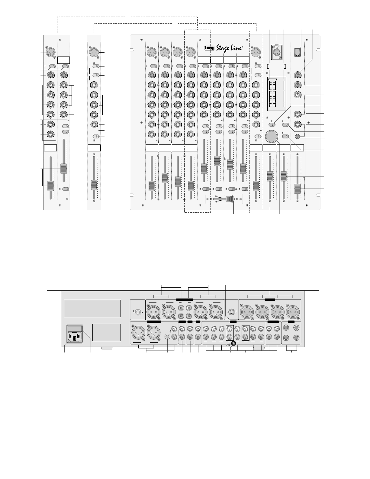
1 Übersicht der Bedienelemente und
Anschlüsse
1.1 Frontplatte des Mischpults
A Mono-Eingangskanal 4 (Kanäle 1 – 3 sind iden-
tisch) und Stereo-Eingangskanal 5 (Kanäle 6 – 8
sind identisch)
B DJ-Mikrofon-Kanal
1 Eingang MIC (XLR, sym.) für den Anschluss
eines Mono-Mikrofons; parallel geschaltet mit
der entsprechenden Buchse MIC (43) auf der
Geräterückseite
2 Umschalttasten zum Anwählen der jeweiligen
Kanaleingänge
3 Gain-Regler zum Einstellen der Eingangsver-
stärkung
4 3fache Klangregelung; bestehend aus Höhen-
regler HIGH, Mittenregler MID (semiparametrisch für die Mono-Kanäle 1–4) und Tiefenregler LOW
5 Regler zum Einstellen der Filterfrequenz für die
Klangregelung im Mittenbereich
6 Balanceregler
7 Übersteuerungsanzeigen PEAK
8 Effekt-Send-Regler zum Einstellen des Pegels,
mit dem die Kanalsignale auf den Post FaderEffektweg gegeben werden
9 Taste STARTzum Fernstarten von Platten- oder
CD-Spielern mit Kontaktsteuerung
10 T aste PFLzum Vorhören des Kanals vor dem Ka-
nalfader (12) über einen an der Buchse PHONES
(33) angeschlossenen Kopfhörer
11 Panoramaregler zum Verteilen der Mono-Signa-
le auf die Stereo-Basis
12 Kanal-Pegelregler (Kanalfader)
13 Zuordnungsschalter für den Crossfader (37); be-
stimmt, auf welche Seite des Crossfaders der
Kanal geschaltet wird:
Taste nicht gedrückt = Kanal auf „A“
Einblenden des Kanals, wenn der Crossfader
nach links geschoben wird;
Ausblenden des Kanals, wenn der Crossfader
nach rechts geschoben wird
Taste gedrückt = Kanal auf „B“
Einblenden des Kanals, wenn der Crossfader
nach rechts geschoben wird;
Ausblenden des Kanals, wenn der Crossfader
nach links geschoben wird
14 Eingang DJ MIC (kombinierte XLR-/6,3-mm-
Klinkenbuchse, sym.) für den Anschluss eines
Mono-Mikrofons an den DJ-Mikrofon-Kanal
15 Talkover-Tasten für das Mikrofon am Kanal DJ
MIC [(15 a) Taste DJ MIC] bzw. für das Mikrofon
an Kanal 1 [(15b) Taste MIC 1]:
Ist die jeweilige Taste gedrückt, werden bei
Durchsagen über das entsprechende Mikrofon
die Pegel der Eingangskanäle 2–8 um den mit
dem Regler TALKOVER(16) eingestellten Wert
abgesenkt.
16 Regler TALKOVER zum Einstellen der automati-
schen Pegelabsenkung (0 –20dB) der Kanäle
2 –8 bei Durchsagen über das Mikrofon (DJMikrofon oder Mikrofon an Kanal 1), dessen
Talkover-Taste (15) gedrückt ist
17 3fache Klangregelung für den DJ-Mikrofon-Ka-
nal; bestehend aus Höhenregler HIGH, Mittenregler MID und Tiefenregler LOW
18 Effekt-Send-Regler zum Einstellen des Pegels,
mit dem die Signale des DJ-Mikrofon-Kanals auf
den Post Fader-Effektweg gegeben werden
19 Übersteuerungsanzeige PEAK für den DJ-Mikro-
fon-Kanal
20 Taste ON AIR zum Ein-/Ausschalten des DJ-
Mikrofons an der Buchse DJ MIC (14)
21 Pegelregler (Fader) des DJ-Mikrofonkanals
22 Stereo-VU-Meter, zeigt – in Abhängigkeit der
Umschalttaste (32) – wahlweise den Masterpegel [je nach Stellung der Taste (29) den Pegel
des Masterkanals A oder des Masterkanals B]
Please unfold page 3. Thus you will always be
able to see the operating elements and connections described.
Contents
1 Operating Elements and Connections . . 4
1.1 Front panel of the mixer . . . . . . . . . . . . . . . 4
1.2 Rear side of the mixer . . . . . . . . . . . . . . . . . 5
2 Safety Notes . . . . . . . . . . . . . . . . . . . . . . . 5
3 Applications . . . . . . . . . . . . . . . . . . . . . . . . 6
4 Connecting the Mixer . . . . . . . . . . . . . . . . 6
4.1 Input channels . . . . . . . . . . . . . . . . . . . . . . . 6
4.2 Outputs . . . . . . . . . . . . . . . . . . . . . . . . . . . . 6
4.3 Connections for an effect unit . . . . . . . . . . . 7
4.4 Connections for remote-controlling of
CD players and turntables . . . . . . . . . . . . . . 7
4.5 Console illumination and mains connection 7
5 Operation . . . . . . . . . . . . . . . . . . . . . . . . . . 7
5.1 Basic settings of the input channels . . . . . . 7
5.2 Settings for the subwoofer and the monitor
system . . . . . . . . . . . . . . . . . . . . . . . . . . . . . 8
5.3 Mixing of the audio sources . . . . . . . . . . . . 8
5.4 Crossfading function for the channels 5–8 . 8
5.5 Use of an effect unit . . . . . . . . . . . . . . . . . . 9
5.6 Pre fader listening (PFL) of the
channels 5–8 via headphones . . . . . . . . . . 9
5.7 Talkover function . . . . . . . . . . . . . . . . . . . . . 9
5.8 Sound Boost effect for master channel A . . 9
5.9 Remote-controlling of turntables and
CD players . . . . . . . . . . . . . . . . . . . . . . . . . 9
6 Specifications . . . . . . . . . . . . . . . . . . . . . 10
1 Operating Elements and Connections
1.1 Front panel of the mixer
A Mono input channel 4 (channels 1 to 3 are ident-
ical) and stereo input channel 5 (channels 6 to 8
are identical)
B DJ microphone channel
1 MIC input (XLR, bal.) for the connection of a mono
microphone; connected in parallel to the corresponding jack MIC (43) on the rear side of the unit
2 Selector buttons to select the respective channel
inputs
3 Gain controls for adjusting the input amplification
4 3-way equalizer; consisting of HIGH, MID (semi-
parametrical for the mono channels 1 to 4), and
LOW controls
5 Control for adjusting the filter frequency for the
equalizer in the midrange
6 Balance control
7 Overload indications PEAK
8 Effect send control for adjusting the level by
which the channel signals are fed to the post
fader effect way
9 STARTbutton for remote starting of turntables or
CD players with contact control
10 PFL button for pre fader listening of the channel
ahead of the channel faders (12) via headphones connected to the PHONES jack (33)
11 Panorama control for distributing the mono sig-
nals to the stereo basis
12 Channel level controls (channel faders)
13 Assign switch for the crossfader (37); determines
to which side of the crossfader the channel is
switched:
Button not pressed = channel to “A”
the channel is faded in if the crossfader is
moved to the left;
the channel is faded out if the crossfader is
moved to the right
Button pressed = channel to “B”
the channel is faded in if the crossfader is
moved to the right;
the channel is faded out if the crossfader is
moved to the left
14 DJ MIC input (combined XLR /6.3mm jack, bal.)
for the connection of a mono microphone to the
DJ microphone channel
15 Talkover buttons for the microphone on the DJ
MIC channel [(15a) DJ MIC button] or for the
microphone on channel 1 [(15b) MIC 1 button]:
If the respective button is pressed, in case of
announcements via the corresponding microphone the levels of the input channels 2 to 8 are
attenuated by the value adjusted with the TALKOVER control (16)
16 TALKOVER control for adjusting the automatic
level attenuation (0 – 20 dB) of channels 2 to 8
in case of announcement via the microphone (DJ
microphone or microphone on channel 1) of
which the talkover button (15) is pressed
17 3-way equalizer for the DJ microphone channel;
consisting of the HIGH, MID, and LOW controls
18 Effect send control for adjusting the level by
which the signals of the DJ microphone channel
are fed to the post fader effect way
19 Overload indication PEAK for the DJ microphone
channel
20 Button ON AIR for switching on and off the DJ
microphone on the DJ MIC jack (14)
21 Level control (fader) of the DJ microphone channel
22 Stereo VU meter, depending on the selector but-
ton (32) it shows either the master level [according to the position of the button (29) the level of
master channel Aor of master channel B] or the
pre fader level of the input channel of which the
PFL button (10) is pressed
23 4-pole XLR jack LAMP for the connection of a
console lamp (12V/5 W max.)
24 Mono VU meter, depending on the selector but-
ton (34) it shows either the level of the subwoofer
4
GB
D
A
CH

oder den Pre Fader-Pegel des Eingangskanals,
dessen Taste PFL (10) gedrückt ist
23 4-polige XLR-Buchse LAMP zum Anschluss
einer Pultleuchte (12V/5 W max.)
24 Mono-VU-Meter, zeigt – in Abhängigkeit der Um-
schalttaste (34) – wahlweise den Pegel der Subwoofer-Ausgänge (46) oder den Pegel des Monitorausgangs BOOTH (48)
25 Ein-/Ausschalter POWER des Mischpults
26 Pegelregler BOOTH für den Monitorausgang
BOOTH (48)
27 Pegelregler SUBWOOFER LEVEL für die Sub-
woofer-Ausgänge (46)
28 Regler SUBWOOFER FREQ. zum Einstellen der
Grenzfrequenz für den Subwoofer
29 Umschalttaste zum Wählen, welcher der zwei
Masterkanäle vom Stereo-VU-Meter (22) angezeigt und auf den Kopfhörerausgang (33) geschaltet wird [Taste (32) darf nicht gedrückt sein
(„MASTER“)]
Taste nicht gedrückt:
Masterkanal A angewählt
Taste gedrückt:
Masterkanal B angewählt
30 Effekt-Send-Summenregler zur Pegeleinstellung
der zum Effektgerät abgehenden Signale
31 Return-Regler zur Pegeleinstellung der vom
Effektgerät zurückkommenden Signale
32 Umschalttaste für den Kopfhörerausgang (33)
und das Stereo-VU-Meter (22)
Taste nicht gedrückt:
Der Masterpegel – je nach Stellung der Taste
(29) der Pegel des Masterkanals A oder des
Masterkanals B – wird über den Kopfhörer abgehört und vom Stereo-VU-Meter angezeigt.
Taste gedrückt:
Der Pre-Fader-Pegel des Eingangskanals, dessen Taste PFL (10) gedrückt ist, wird über den
Kopfhörer abgehört und vom Stereo-VU-Meter
angezeigt.
33 6,3-mm-Klinkenbuchse PHONES zum Anschluß
eines Stereo-Kopfhörers (Impedanz ≥ 8Ω)
34 Umschalttaste für das Mono-VU-Meter (24)
Taste nicht gedrückt:
Das Mono-VU-Meter zeigt den Pegel des Monitorausgangs BOOTH (48) an.
Taste gedrückt :
Das Mono-VU-Meter zeigt den Pegel der Subwoofer-Ausgänge (46) an.
35 Pegelregler (Masterfader) für den Masterkanal B
36 Pegelregler für den Kopfhörer an der Buchse
PHONES (33)
37 Überblendregler (Crossfader) zum Überblenden
zwischen den Kanälen 5–8; die Kanäle werden
mit ihren Zuordnungsschaltern (13) auf die gewünschte Seite des Crossfaders gelegt
[Wird die Überblendfunktion nicht benötigt, die Zuordnungsschalter nicht drücken und den Crossfader ganz nach links auf „A“ schieben.]
38 Pegelregler (Masterfader) für den Masterkanal A
39 Taste SOUND BOOST zur kurzzeitigen Pegel-
anhebung (ca. 12 dB) des Masterkanals A für
spezielle Sound-Effekte
1.2 Rückseite des Mischpults
40 Stereo-Ausgänge des Masterkanals B – wahl-
weise XLR (sym.) oder Cinch – zum Anschluss
einer Endstufe
41 Stereo-Ausgänge des Masterkanals A – wahl-
weise XLR (sym.) oder Cinch – zum Anschluss
einer Endstufe
42 Eingänge PHONO (Cinch) für Kanal 6 und 7 zum
Anschluss von Plattenspielern mit Magnetsystem
43 Eingänge MIC (XLR, sym.) zum Anschluss von
Mono-Mikrofonen an die Kanäle 1 – 4; parallel
geschaltet mit den Buchsen MIC (1) auf der
Frontplatte
44 Buchse für das Netzkabel: Anschluss des Kabels
an eine Netzsteckdose (230V~/50Hz)
45 Sicherungsfach; eine durchgebrannte Sicherung
nur durch eine gleichen Typs ersetzen
46 Stereo-Ausgänge – wahlweise XLR (sym.) oder
Cinch – zum Anschluss der Subwoofer-Endstufe; die Ausgänge können mit dem Umschalter
(47) auch auf mono umgeschaltet werden
47 Umschalter für die Subwoofer-Ausgänge (46)
Taste nicht gedrückt:
Die Ausgänge sind stereo geschaltet.
Taste gedrückt:
Die Ausgänge sind mono geschaltet.
48 Stereo-Ausgang BOOTH (Cinch) zum Anschluss
einer Monitoranlage
49 Stereo-Ausgang REC (Cinch) zum Anschluss
eines Tonaufnahmegerätes; der Aufnahmepegel
ist unabhängig von der Stellung der Masterfader
A (38) und B (35)
50 Anschlüsse (Cinch) für ein Mono-Effektgerät
Ausgangsbuchse SEND:
Anschluss an den Eingang des Effektgerätes
Eingangsbuchse RETURN:
Anschluss an den Ausgang des Effektgerätes
51 Anschluss für einen gemeinsamen Massepunkt,
z.B. für angeschlossene Plattenspieler
52 Eingänge LINE bzw. CD (Cinch) für die Kanäle
1 – 4 (mono) und die Kanäle 5 – 8 (stereo) zum
Anschluss von Geräten mit Line-Pegel-Ausgängen (z. B. Mini-Disk-Recorder, CD-Spieler, Tapedeck)
53 6,3-mm-Klinkenbuchsen START für den An-
schluss von Steuerleitungen zum Fernstarten
von Platten- oder CD-Spielern mit Kontaktsteuerung
outputs (46) or the level of the monitor output
BOOTH (48)
25 On/Off switch POWER of the mixer
26 Level control BOOTH for the monitor output
BOOTH (48)
27 Level control SUBWOOFER LEVEL for the sub-
woofer outputs (46)
28 Control SUBWOOFER FREQ. for adjusting the
cut-off frequency for the subwoofer
29 Selector button to decide which of the two mas-
ter channels is displayed by the stereo VU meter
(22) and switched to the headphone output (33)
[button (32) must not be pressed (“MASTER”)]
Button not pressed:
master channel Ais selected
Button pressed:
master channel B is selected
30 Effect Send master control for level adjustment
of the signals passing on to the effect unit
31 Return control for level adjustment of the signals
returning from the effect unit
32 Selector button for the headphone output (33)
and the stereo VU meter (22)
Button not pressed:
According to the position of the button (29), the
level of master channel Aor of master channel
B is monitored via headphones and displayed
by the stereo VU meter.
Button pressed:
The pre fader level of the input channel of
which the PFL button (10) is pressed is monitored via the headphones and displayed by the
stereo VU meter.
33 6.3mm PHONES jack for the connection of
stereo headphones (impedance ≥ 8Ω)
34 Selector button for the mono VU meter (24)
Button not pressed:
The mono VU meter shows the level of the
monitor output BOOTH (48).
Button pressed:
The mono VU meter shows the level of the
subwoofer outputs (46).
35 Level control (master fader) for the master chan-
nel B
36 Level control for the headphones connected to
the PHONES jack (33)
37 Crossfader for fading between channels 5 to 8;
the channels are placed with their assign switches
(13) to the desired side of the crossfader
[If the crossfader function is not necessary, do
not press the assign switches and move the
crossfader to the left to “A” until it stops.]
38 Level control (master fader) for the master chan-
nel A
39 Button SOUND BOOST for short-time level
boosting (approx. 12dB) of master channel Afor
special sound effects
1.2 Rear side of the mixer
40 Stereo outputs of master channel B – either XLR
jacks (bal.) or phono jacks – for the connection of
a power amplifier
41 Stereo outputs of master channel A– either XLR
jacks (bal.) or phono jacks – for the connection of
a power amplifier
42 PHONO inputs (phono jacks) for channels 6 and
7 for the connection of turntables with magnetic
system
43 MIC inputs (XLR, bal.) for the connection of
mono microphones on channels 1 to 4; connected in parallel to the MIC jacks (1) on the front
panel
44 Jack for the mains cable: connection of the cable
to a mains socket (230V~/50Hz)
45 Fuse compartment; replace a burnt-out fuse by
one of the same type only
46 Stereo outputs – alternatively XLR jacks (bal.) or
phono jacks – for the connection of the sub-
woofer power amplifier; the outputs can also be
switched to mono with the selector switch (47)
47 Selector switch for the subwoofer outputs (46)
Button not pressed:
The outputs are switched to stereo.
Button pressed:
The outputs are switched to mono.
48 Stereo output BOOTH (phono jacks) for the
connection of a monitor system
49 Stereo output REC (phono jacks) for the connec-
tion of an audio recording unit; the recording
level is independent of the position of the master
faders A(38) and B (35)
50 Connections (phono jacks) for a mono effect unit
Output jack SEND:
connection to the input of the effect unit
Input jack RETURN:
connection to the output of the effect unit
51 Connection for a common grounding point, e.g.
for connected turntables
52 LINE and CD inputs (phono jacks) for channels 1
to 4 (mono) and channels 5 to 8 (stereo) for the
connection of units with line level outputs (e. g.
mini disk recorder, CD player, tape deck)
53 6.3mm START jacks for the connection of con-
trol lines for remote-controlling of turntables or
CD players with contact control
5
GB
D
A
CH

2 Hinweise für den sicheren Gebrauch
Dieses Gerät entspricht der Richtlinie für elektromagnetische Verträglichkeit 89/336/EWG und der Niederspannungsrichtlinie 73/23/EWG.
Beachten Sie unbedingt die folgenden Punkte:
●
Das Gerät ist nur zur Verwendung in Innenräumen
geeignet. Schützen Sie es vor Tropf- und Spritzwasser, hoher Luftfeuchtigkeit und Hitze (zulässiger Einsatztemperaturbereich 0–40°C).
●
Stellen Sie keine mit Flüssigkeit gefüllten Gefäße,
z.B. Trinkgläser, auf das Gerät.
●
Nehmen Sie das Gerät nicht in Betrieb bzw. ziehen
Sie sofort den Netzstecker aus der Steckdose:
1. wenn sichtbare Schäden am Gerät oder an der
Netzanschlussleitung vorhanden sind,
2. wenn nach einem Sturz oder Ähnlichem der
Verdacht auf einen Defekt besteht,
3. wenn Funktionsstörungen auftreten.
Lassen Sie das Gerät in jedem Fall in einer Fachwerkstatt reparieren.
●
Ziehen Sie den Netzstecker nie an der Zuleitung
aus der Steckdose, fassen Sie immer am Stecker
an.
●
Verwenden Sie für die Reinigung nur ein trockenes, weiches Tuch, niemals Wasser oder Chemikalien.
●
Wird das Gerät zweckentfremdet, falsch bedient
oder nicht fachgerecht repariert, kann für eventuelle Schäden keine Haftung übernommen werden.
●
Soll das Gerät endgültig aus dem Betrieb genommen werden, übergeben Sie es zur umweltgerechten Entsorgung einem örtlichen Recyclingbetrieb.
3 Einsatzmöglichkeiten
Das Mischpult MPX-804 mit acht Eingangskanälen
(4 Mono-Kanäle, 4 Stereo-Kanäle) und einem zusätzlichen DJ-Mikrofon-Kanal ist für professionelle
DJ-Anwendungen (z. B. in Clubs oder Discos, auf
Tanzveranstaltungen etc.) geeignet.
Das Gerät kann sowohl frei aufgestellt als auch in
ein Bedienpult eingebaut werden. Es eignet sich
ebenso für die Montage in ein Rack (482 mm / 19").
Für die Rackmontage wird eine Höhe von 10 HE
(Höheneinheiten) = 444,5mm benötigt.
4 Mischpult anschließen
Vor dem Anschließen von Geräten bzw . vor dem Ändern bestehender Anschlüsse das Mischpult ausschalten.
4.1 Eingangskanäle
Die Tonquellen an die entsprechenden Eingänge der
Eingangskanäle anschließen [Stereo-Eingänge für
die Kanäle 5–8 (weiße Buchse L= linker Kanal; rote
Buchse R = rechter Kanal), Mono-Eingänge für die
Kanäle 1–4 und den DJ-Mikrofon-Kanal]:
-
Mono-Mikrofone an die Buchsen MIC (1 oder 43);
-
ein DJ-Mono-Mikrofon an die Buchse DJ MIC (14);
-
Geräte mit Line-Pegel-Ausgang (z. B. MiniDisk-
Recorder, CD-Spieler, Tapedeck) an die Buchsen
CD oder LINE (52);
-
Plattenspieler mit Magnetsystem an die Buchsen
PHONO (42). Die Klemmschraube (51) kann als
gemeinsamer Massepunkt genutzt werden: Den
Masseanschluss des Plattenspielers mit der
Klemmschraube verbinden.
4.2 Ausgänge
1) Die Verstärker bzw. andere nachfolgende Geräte
mit Line-Eingangspegel (z.B. zweites Mischpult)
an die entsprechenden Ausgangsbuchsen der
beiden Masterkanäle anschließen:
Die Signalsumme des Masterkanals A steht
an den beiden Stereo-Ausgängen (41) zur Verfügung und die Signalsumme des Masterkanals B
an den beiden Stereo-Ausgängen (40); es kann
wahlweise der symmetrische XLR-Ausgang oder
der asymmetrische Cinch-Ausgang des Masterkanals verwendet werden.
2) Den Verstärker des Subwoofers an einen der
Stereo-Ausgänge SUBWOOFER (46) anschließen: entweder an den symmetrischen XLR-Ausgang oder an den asymmetrischen Cinch-Ausgang. Durch Drücken der Umschalttaste (47)
können die beiden Stereo-Ausgänge auf mono
geschaltet werden.
3) Ist eine Monitoranlage vorhanden, den Verstärker
der Monitoranlage an den Ausgang BOOTH (48)
anschließen.
4) Sollen Tonaufnahmen gemacht werden, das Aufnahmegerät an den Ausgang REC (49) anschließen. Der Aufnahmepegel ist unabhängig von der
Stellung der beiden Masterfader (35 und 38).
5) Über einen Stereo-Kopfhörer kann sowohl der Pre
Fader-Pegel jedes Eingangskanals 5–8 sowie
der Pegel des mit der Taste (29) gewählten Masterkanals abgehört werden. Den Kopfhörer (Impedanz ≥ 8Ω) an die Buchse PHONES (33) anschließen.
4.3 Anschlüsse für ein Effektgerät
Über die Buchsen SEND und RETURN (50) ist es
möglich, Signale der Eingangskanäle 1 –4 sowie
des DJ-Mikrofon-Kanals aus dem Mischpult herauszuführen, durch ein angeschlossenes Mono-Effektgerät (z. B. Equalizer, Hallgerät) zu schleifen und
wieder in das Mischpult zurückzuführen. Der EffektSend-Weg ist „Post Fader“ geschaltet, d.h. die Kanalsignale werden hinter den Kanalfadern (12 bzw.
21) auf den Effektweg gelegt.
1) Den Eingang des Effektgerätes an die Buchse
SEND anschließen.
2) Den Ausgang des Effektgerätes an die Buchse
RETURN anschließen.
Achtung! Das Gerät wird mit lebensgefährlicher
Netzspannung (230 V~) versorgt. Nehmen Sie deshalb niemals selbst Eingriffe im Gerät vor. Durch unsachgemäßes Vorgehen besteht die Gefahr
eines elektrischen Schlages. Außerdem
erlischt beim Öffnen des Gerätes jeglicher Garantieanspruch.
2 Safety Notes
This unit corresponds to the directive for electromagnetic compatibility 89/ 336 /EEC and to the low
voltage directive 73/23/EEC.
Please observe the following items in any case:
●
The unit is suitable for indoor use only. Protect it
against dripping water and splash water, high air
humidity, and heat (admissible ambient temperature range 0–40°C).
●
Do not place any vessel filled with liquid on the
unit, e.g. a drinking glass.
●
Do not operate the unit or immediately disconnect
the plug from the mains socket
1. if there is visible damage to the unit or to the
mains cable,
2. if a defect might have occurred after the unit
was dropped or suffered a similar accident,
3. if malfunctions occur.
In any case the unit must be repaired by skilled
personnel.
●
Never pull the mains cable for disconnecting the
mains plug from the socket.
●
For cleaning only use a dry, soft cloth, by no
means chemicals or water.
●
No liability for any damage will be accepted if the
unit is used for other purposes than originally
intended, if it is not correctly operated or not repaired in an expert way.
●
If the unit is to be put out of operation definitively,
take it to a local recycling plant for a disposal
which is not harmful to the environment.
●
Important for U.K. Customers!
The wires in this mains lead are coloured in accordance with the following code:
green/yellow = earth
blue = neutral
brown = live
As the colours of the wires in the mains lead of this
appliance may not correspond with the coloured
markings identifying the terminals in your plug,
proceed as follows:
1. The wire which is coloured green and yellow
must be connected to the terminal in the plug
which is marked with the letter E or by the earth
symbol , or coloured green or green and
yellow.
2. The wire which is coloured blue must be connected to the terminal which is marked with the
letter N or coloured black.
3. The wire which is coloured brown must be connected to the terminal which is marked with the
letter L or coloured red.
Warning
-
This appliance must be earthed.
3 Applications
The mixer MPX-804 with eight input channels
(4 mono channels, 4 stereo channels) and an additional DJ microphone channel is suitable for professional DJ applications (e. g. in clubs or discos, on
dancing events, etc.).
The unit can be placed as a table top unit as well
as be installed into a console. It is suitable for rack
mounting (482mm/19") as well. For rack mounting a
height of 10 rack spaces = 444.5 mm is necessary.
4 Connecting the Mixer
Prior to connection of units or changing of existing
connections switch off the mixer.
4.1 Input channels
Connect the audio sources to the corresponding
inputs of the input channels [stereo inputs for channels 5 to 8 (white jack L = left channel; red jack R =
right channel), mono inputs for channels 1 to 4 and
the DJ microphone channel]:
-
mono microphones to the MIC jacks (1 or 43);
-
DJ microphone to the DJ MIC jack (14);
-
units with line level output (e.g. minidisk recorder, CD player, tape deck) to the CD or LINE
jacks (52);
-
record players with magnetic system to the
PHONO jacks (42). The clamping screw (51) can
be used as common grounding point: connect the
ground connection of the turntable to the clamping screw.
4.2 Outputs
1) Connect the amplifier or other following units with
line input level (e. g. second mixer) to the corresponding output jacks of the two master channels:
The master signal of master channel Ais present at the two stereo outputs (41) and the master
signal of master channel B is present at the two
stereo outputs (40); it is possible to use either the
balanced XLR output or the unbalanced phono
output of the master channel.
2) Connect the amplifier of the subwoofer to one of
the stereo outputs SUBWOOFER (46): either to
the balanced XLR output or the unbalanced
phono output. By pressing the selector button (47)
the two stereo outputs can be switched to mono.
3) If a monitor system is provided, connect the
amplifier of the monitor system to the BOOTH
output (48).
4) For audio recordings connect the recording unit
to the REC output (49). The recording level is
independent of the position of the two master
faders (35 and 38).
5) Via stereo headphones it is possible to monitor
the pre fader level of each input channel 5 to 8 as
Attention! The unit is supplied with hazardous
mains voltage (230 V~). Leave servicing to skilled personnel only. Inexpert
handling may cause an electric shock
hazard. Furthermore, any guarantee
claim will expire if the unit has been
opened.
6
GB
D
A
CH
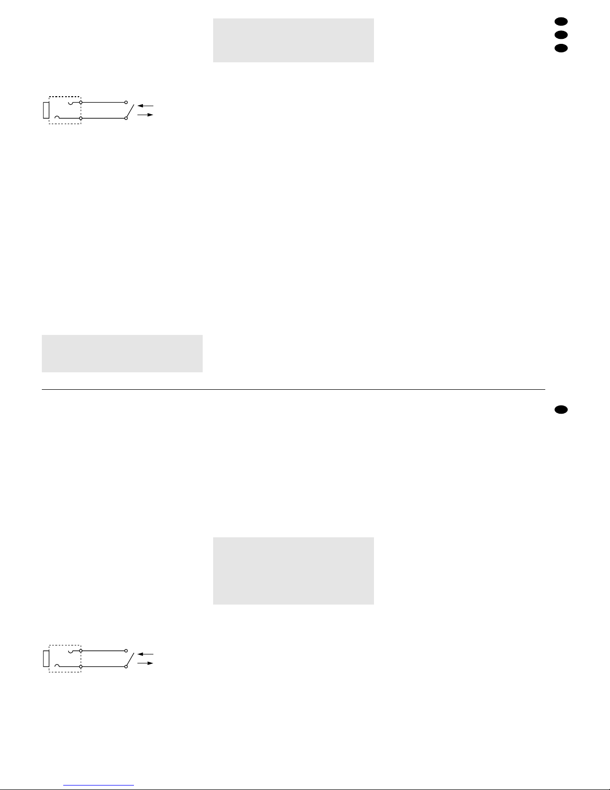
4.4 Anschlüsse zur Fernsteuerung von
CD-Spielern und Plattenspielern
Kontaktsteuerbare CD- bzw. Plattenspieler an den
Kanälen 5 bis 8 können über das Mischpult ferngestartet werden. Dazu den jeweiligen Steuereingang
des angeschlossenen Gerätes mit der entsprechenden 6,3-mm-Klinkenbuchse START(53) des Mischpults verbinden
Abb. 3: Fernstartschalter für einen Kanal
4.5 Pultbeleuchtung und Netzanschluss
Zur Pultbeleuchtung kann an die XLR-Buchse LAMP
(23) eine Schwanenhalsleuchte (12V/5 W max.) angeschlossen werden, z.B. die Leuchte GNL-405 aus
dem Programm von „img Stage Line“. Die Leuchte
wird mit dem Mischpult ein- und ausgeschaltet.
Zuletzt das Netzkabel mit der Buchse (44) verbinden und den Stecker des Netzkabels in eine
Steckdose (230V~/50Hz) stecken.
5 Bedienung
Vor dem Einschalten sollten die beiden Masterfader
A (38) und B (35) sowie der Monitorregler BOOTH
(26) und der Pegelregler (27) für den SubwooferVerstärker auf Minimum gestellt werden, um starke
Einschaltgeräusche zu vermeiden.
Das Mischpult mit dem Schalter POWER (25)
einschalten. Bei eingeschaltetem Mischpult leuchten in beiden VU-Metern (22 und 24) die LEDs „ON“.
Dann die angeschlossenen Geräte einschalten.
5.1 Grundeinstellungen der Eingangskanäle
Für eine optimale Pegeleinstellung der an den Eingangskanälen angeschlossenen Tonquellen alle
Gain-Regler (3), Klangregler (4 und 17), Balanceregler (6) und Panoramaregler (11) zunächst in die Mittelposition stellen und den Effekt-Summenregler SEND
(30) ganz zurückdrehen. Die Zuordnungsschalter
(13) der Kanäle 5 – 8 nicht drücken und den Crossfader (37) ganz nach links in Position „A“ schieben.
1) Zum Einschalten des DJ-Mikrofons die Taste ON
AIR (20) drücken.
2) Mit den Umschalttasten (2) die an den Kanälen
1–8 angeschlossenen Signalquellen anwählen.
Taste nicht gedrückt:
Bei Kanal 1–4 ist der Eingang LINE angewählt, bei Kanal 5–8 der Eingang CD.
Taste gedrückt:
Bei Kanal 1–4 ist der Eingang MIC angewählt,
bei Kanal 5–8 der Eingang LINE (Kanal 5 + 8)
bzw. der Eingang PHONO (Kanal 6 + 7).
3) Mit den Masterfadern wird der Gesamtpegel aller
angeschlossenen Tonquellen eingestellt, der an
den Masterausgängen zur Verfügung steht: Masterfader A(38) für die beiden Masterausgänge A
(41), Masterfader B (35) für die beiden Masterausgänge B (40).
Den Regler desjenigen Masterkanals, der für
die Grundeinstellung der Eingangskanäle genutzt wird, auf ca.
2
/
3 des Maximums, z. B. auf
Position 7, stellen.
4) Die Umschalttaste (32) für das Stereo-VU-Meter
(22) darf nicht gedrückt sein: Das VU-Meter zeigt
dann den Pegel eines der Masterkanäle an – je
nach Stellung des Umschalters (29) den des
Masterkanals Aoder den des Masterkanals B.
Mit der Umschalttaste (29) das Stereo-VUMeter auf denjenigen Masterkanal einstellen, der
für die Grundeinstellung der Eingangskanäle genutzt wird:
Taste nicht gedrückt:
Der Pegel des Masterkanals Awird angezeigt.
Taste gedrückt:
Der Pegel des Masterkanals B wird angezeigt.
5) Zum Aussteuern eines Kanals die Fader (12 bzw.
21) der übrigen Kanäle auf Minimum stellen und
die Tonsignale (Testsignale oder Musikstücke)
auf den jeweiligen Eingangskanal geben.
6) Anhand des Stereo-VU-Meters mit dem Kanalfader den Pegel des Kanals ausregeln. Optimale
Aussteuerung liegt vor, wenn bei den lautesten
Passagen der 0-dB-Bereich des VU-Meters kurz
aufleuchtet. Bei Anzeigen über 0 dB ist der Kanal
übersteuert. Übersteuerungen werden auch durch
die Anzeige PEAK (7 bzw. 19) angezeigt. Sie sollte gar nicht bzw. bei Lautstärkespitzen nur kurz
aufleuchten.
Der Fader sollte nach der Pegeleinstellung
auf ca.
2
/3
des Maximums stehen, damit zum Einund Ausblenden genügend Reglerweg vorhanden ist.
7) Bei sehr wenig oder sehr weit aufgezogenem
Fader muss der Pegel durch Regulierung der
Eingangsverstärkung angepasst werden: Den
Gain-Regler (3) des Kanals entsprechend zurückbzw. aufdrehen.
Für die Kanäle 5 – 8 lässt sich die Eingangsverstärkung durch Anzeige des Pre FaderPegels optimal einstellen. Dazu das Stereo-VUMeter durch Drücken der Taste (32) in den
Anzeigemodus „PFL“ umschalten und die Taste
PFL (10) des Kanals drücken: Das VU-Meter
zeigt jetzt den Signalpegel des Kanals vor dem
Kanalfader an. Den GAIN-Regler des Kanals so
einstellen, dass bei den lautesten Passagen die
0-dB-LEDs kurz aufleuchten und der Bereich
über 0dB gar nicht leuchtet.
Das menschliche Ohr gewöhnt sich an
große Lautstärken und empfindet sie
nach einiger Zeit als nicht mehr so
hoch. Darum eine hohe Lautstärke nach
der Gewöhnung nicht weiter erhöhen.
Vorsicht! Stellen Sie die Lautstärke der Audio-
anlage und die Kopfhörerlautstärke nie
sehr hoch ein. Hohe Lautstärken können auf Dauer das Gehör schädigen!
START
Start
Stop
/
Pause
well as the level of the master channel selected
with button (29). Connect the headphones (impedance ≥ 8Ω) to the PHONES jack (33).
4.3 Connections for an effect unit
Via the SEND and RETURN jacks (50) it is possible
to route signals of the input channels 1 to 4 as well
as of the DJ microphone channel out of the mixer, to
feed them through a connected mono effect unit
(e.g. equalizer, reverberation unit), and to feed them
back to the mixer again. The effect send way is
switched “post fader”, i. e. the channel signals are
guided after the channel faders to the effect way.
1) Connect the input of the effect unit to the SEND
jack.
2) Connect the output of the effect unit to the RETURN jack.
4.4 Connections for remote-controlling of
CD players and turntables
CD players and turntables with contact control on
the channels 5 to 8 can be remote-controlled via the
mixer. For this connect the respective control input
of the connected unit to the corresponding 6.3 mm
STARTjack (53) of the mixer.
Fig. 3: Remote start switch for a channel
4.5 Console illumination and
mains connection
For the console illumination a gooseneck lamp
(12V/5 W max.) may be connected to the XLR jack
LAMP (23), e. g. the lamp GNL-405 of the “img
Stage Line” range. The lamp is switched on and off
with the mixer.
Finally connect the mains cable to the jack (44)
and connect the plug of the mains cable to a mains
socket (230V~/50Hz).
5 Operation
Prior to switching on, the two master faders A (38)
and B (35) as well as the monitor control BOOTH
(26) and the level control (27) for the subwoofer
amplifier should be set to minimum to avoid loud
switching noise.
Switch on the mixer with the POWER switch (25).
With the mixer switched on, the LEDs “ON” in the
two VU meters (22 and 24) light up. Then switch on
the connected units.
5.1 Basic settings of the input channels
For an optimum level setting of the audio sources
connected to the input channels, set all gain controls
(3), equalizers (4 and 17), balance controls (6), and
panorama controls (11) to mid-position first and turn
back the effect master control SEND (30) completely. Do not press the assign switches (13) of channels
5 to 8, and place the crossfader (37) to the left to
position “A” until it stops.
1) To switch on the DJ microphone, press the ON
AIR button (20).
2) Select with the selector buttons (2) the signal
sources connected to the channels 1 to 8.
Button not pressed:
For channels 1 to 4 the LINE input is selected,
for channels 5 to 8 the CD input.
Button pressed:
For channels 1 to 4 the MIC input is selected,
for channels 5 to 8 the LINE input (channels 5
and 8) or the PHONO input (channels 6 and 7).
3) With the master faders the overall level of all
connected audio sources is adjusted which is
present at the master outputs: master fader A
(38) for the two master outputs A (41), master
fader B (35) for the two master outputs B (40).
Set the control of that master channel, which
is used for the basic setting of the input channels,
to approx.
2
/3 of the maximum, e.g. to position 7.
4) The selector button (32) for the stereo VU meter
(22) must not be pressed: Then the VU meter
shows the level of one of the master channels
– according to the position of the selector switch
(29) the level of master channel A or of master
channel B.
Adjust with the selector button (29) the stereo
VU meter to that master channel which is used
for the basic setting of the input channels:
Button not pressed:
The level of master channel Ais displayed.
Button pressed:
The level of master channel B is displayed.
5) To control a channel, set the faders (12 or 21) of
the remaining channels to minimum and feed the
audio signals (test signals or music pieces) to the
respective input channel.
6) By means of the stereo VU meter control the level
of the channel with the channel fader. The optimum level is obtained if the 0dB range of the VU
meter shortly lights up during music peaks. In
case of displays above 0dB the channel is overloaded. Overload is also displayed by the PEAK
indication (7 or 19). It should not light up at all
resp. only shortly light up in case of volume peaks.
The fader should be set to approx.
2
/3 of its
maximum after level adjustment so that there is
sufficient control way for fading in and fading out.
7) If the fader is moved up only very little or very
much, the level must be matched by adjusting the
Caution! Do not adjust the audio system or the
headphones to a very high volume. Permanent high volumes may damage
your hearing! The human ear will get
accustomed to high volumes which do
not seem to be that high after some
time. Therefore, do not further increase
a high volume after getting used to it.
START
Start
Stop
/
Pause
7
GB
D
A
CH

8) Das Stereo-VU-Meter durch Lösen der Taste (32)
wieder in den Anzeigemodus „MASTER“ schalten, und mit der 3fachen Klangregelung (4 bzw.
17) des Kanals das gewünschte Klangbild einstellen: Die Höhen (Regler HIGH), Mitten (unterer Regler MID) und Tiefen (Regler LOW) lassen
sich für alle Eingangskanäle bis max. 12dB
anheben und bis max. 12 dB (Kanäle 1 – 4 und
DJ-Mikrofonkanal) bzw. 30dB (Kanäle 5–8)
dämpfen. Stehen die Regler in Mittelstellung, findet keine Frequenzgangbeeinflussung statt.
Die Filterfrequenzen für die Höhen- und Tiefenregelung sind bei allen Eingangskanälen fest:
10 kHz für den Höhenbereich und 100Hz für den
Tiefenbereich. Für die Kanäle 1–4 lässt sich die
Filterfrequenz für den Mittenbereich stufenlos mit
dem oberen Regler MID (5) von 500Hz bis 5 kHz
einstellen.
Hinweis: Klangeinstellungen wirken sich auf die
Pegel aus. Deshalb nach einer Klangregulierung
den Kanalpegel anhand des VU-Meters kontrollieren und ggf. korrigieren.
9) Mit dem Panoramaregler PAN (11) die Signale
wie gewünscht auf der Stereo-Basis verteilen (für
die Mono-Kanäle 1 – 4) bzw. mit dem Balanceregler BAL(6) die gewünschte Balance einstellen
(für die Stereo-Kanäle 5–8).
Die Einstellungen für die übrigen belegten Eingangskanäle in der gleichen Weise wie oben beschrieben durchführen.
5.2 Einstellungen für den Subwoofer und die
Monitoranlage
Wird ein Subwoofer eingesetzt, müssen folgende
Einstellungen vorgenommen werden:
1) Mit dem Regler SUBWOOFER FREQ. (28) die
Grenzfrequenz (60 – 150 Hz) für den Subwoofer
einstellen.
2) Den Umschalter (34) drücken: Das Mono-VUMeter (24) zeigt dann den Pegel an den Subwoofer-Ausgängen (46) an. Dieser ist unabhängig
von den Einstellungen der beiden Masterfader
A (38) und B (35).
3) Anhand des Mono-VU-Meters mit dem Regler
SUBWOOFER LEVEL (27) den gewünschten
Pegel für den Subwoofer-Verstärker einstellen.
Bei Übersteuerungen (Bereich über 0 dB leuchtet) den Pegelregler entsprechend zurückdrehen.
Über eine Monitoranlage kann das laufende Musikprogramm vor den beiden Masterfadern (35 und
38) abgehört werden:
1) Der Umschalter (34) darf nicht gedrückt sein:
Das Mono-VU-Meter (24) zeigt dann den Pegel
am Monitorausgang BOOTH (48) an.
2) Anhand des Mono-VU-Meters mit dem Regler
BOOTH (26) den gewünschten Pegel für die
Monitoranlage einstellen. Bei Übersteuerungen
(Bereich über 0dB leuchtet) den Pegelregler entsprechend zurückdrehen.
5.3 Mischen der Tonquellen
1) Beim Mischen der angeschlossenen Tonquellen
wird die Überblendfunktion normalerweise nicht
benötigt. Darum die Zuordnungsschalter (13) der
Kanäle 5 – 8 auf „A“ schalten (Tasten nicht gedrückt) und den Crossfader (37) ganz nach links
auf Position „A“ schieben.
2) Den Masterfader A (38) oder B (35) so weit aufziehen, dass das Mischungsverhältnis der Tonquellen optimal eingestellt werden kann.
3) Mit den Fadern (12) der Eingangskanäle das gewünschte Lautstärkeverhältnis der T onquellen zueinander einstellen. Wird ein Kanal nicht benutzt,
sollte sein Fader auf Minimum gestellt werden.
4) Mit den Masterfadern jeden Masterkanal anhand
des Stereo-VU-Meters (22) separat ausregeln.
Dazu das VU-Meter auf Anzeige des jeweiligen
Masterkanals umschalten (siehe dazu Kap. 5.1,
Punkt 4).
Die Masterkanäle sind optimal ausgesteuert,
wenn bei den lautesten Passagen der 0-dB-Bereich des VU-Meters kurz aufleuchtet. Bei Über-
steuerungen (Bereich über 0dB leuchtet auf) den
jeweiligen Masterfader und/oder die Fader der
Eingangskanäle entsprechend herunterregeln.
5.4 Überblendfunktion für die Kanäle 5–8
Mit dem Crossfader (37) kann zwischen den vier
Stereo-Kanälen 5–8 in beliebiger Anordnung übergeblendet werden.
1) Die Fader (12) aller nicht benutzten Eingangskanäle auf Minimum stellen und die Kanäle, zwischen denen übergeblendet werden soll, mit
ihren Fadern optimal aussteuern (siehe Kap. 5.1).
2) Die für das Überblenden ausgewählten Kanäle
mit ihren Zuordnungsschaltern (13) auf die gewünschte Seite des Crossfaders schalten:
Taste nicht gedrückt = Kanal auf „A“:
Einblenden des Kanals, wenn der Crossfader
nach links geschoben wird;
Ausblenden des Kanals, wenn der Crossfader
nach rechts geschoben wird
Taste gedrückt = Kanal auf „B“:
Einblenden des Kanals, wenn der Crossfader
nach rechts geschoben wird;
Ausblenden des Kanals, wenn der Crossfader
nach links geschoben wird
3) Mit dem Crossfader kann jetzt zwischen den
gewählten Kanälen übergeblendet werden.
Es ist sowohl ein Überblenden zwischen zwei
Kanälen möglich (z. B. Kanal 5 auf „A“, Kanal 6
auf „B“), es lassen sich aber auch bei Bedarf
mehrere Kanäle mischen und dieses Mischsignal
kann dann zum Überblenden genutzt werden
(z.B. Kanäle 5 und 7 auf „A“, Kanal 8 auf „B“).
4) Mit den Masterfadern A (38) und B (35) für die
Masterkanäle A und B den gewünschten Gesamtpegel einstellen. Jeden Masterkanal anhand
des VU-Meters (22) separat ausregeln. Dazu das
VU-Meter auf Anzeige des jeweiligen Masterkanals umschalten (siehe dazu Kap. 5.1, Punkt 4).
Bei Übersteuerungen (Bereich über 0dB leuchtet
auf) den jeweiligen Masterfader entsprechend
herunterregeln.
input amplification: turn back or turn up the gain
control (3) of the channel correspondingly.
For the channels 5 to 8 the input amplification
can be adjusted in an optimum way by the display of the pre fader level. For this switch the
stereo VU meter to the display mode “PFL” by
pressing the button (32), and press the button
PFL (10) of the channel: the VU meter now
shows the signal level of the channel ahead of
the channel fader. Set the GAIN control of the
channel so that the 0 dB LEDs shortly light up
during music peaks and the range above 0 dB
does not light up at all.
8) Set the stereo VU meter to the display mode
“MASTER” again by releasing the button (32)
and adjust the desired sound with the 3-way
equalizer (4 or 17) of the channel: The high frequencies (HIGH control), the mid-frequencies
(lower MID control), and the bass frequencies
(LOW control) can be boosted up to max. 12dB
for all input channels and attenuated up to max.
12dB (channels 1 to 4 and DJ microphone channel) or 30dB (channels 5 to 8). If the controls are
in mid-position, there will be no influence on the
frequency response.
The filter frequencies for the control of high
and bass frequencies are fixed for all input channels: 10 kHz for the high frequency range and
100 Hz for the bass frequency range. For the
channels 1 to 4 the filter frequency for the midrange can continuously be adjusted with the
upper MID control (5) from 500Hz to 5kHz.
Note: Sound adjustments influence the levels.
Therefore, after a sound adjustment, check the
channel level by means of the VU meter, and if
necessary, correct it.
9) With the panorama control PAN (11) distribute
the signals as desired to the stereo basis (for the
mono channels 1 to 4) or adjust the desired
balance with the balance control BAL (6) (for the
stereo channels 5 to 8).
Make the adjustments for the remaining connected
input channels as described above.
5.2 Settings for the subwoofer and the
monitor system
If a subwoofer is used, the following settings have
to be made:
1) Set the cut-off frequency (60 – 150 Hz) for the sub-
woofer with the SUBWOOFER FREQ. control (28).
2) Press the selector switch (34): the mono VU
meter (24) then shows the level at the subwoofer
outputs (46). This is independent of the settings
of the two master faders A(38) and B (35).
3) By means of the mono VU meter adjust the desi-
red level for the subwoofer amplifier with the
SUBWOOFER LEVEL (27) control. In case of
overload (range above 0dB lights up), turn back
the level control correspondingly.
Via a monitor system the music programme cur-
rently played can be monitored ahead of the two
master faders (35 and 38):
1) The selector switch (34) must not be pressed: the
mono VU meter (24) then shows the level at the
monitor output BOOTH.
2) By means of the mono VU meter adjust the de-
sired level for the monitor system with the
BOOTH control (26). In case of overload (range
above 0dB lights up) turn back the level control
correspondingly.
5.3 Mixing of the audio sources
1) When mixing the connected audio sources, the
crossfading function is usually not necessary.
Therefore, switch the assign switches (13) of
channels 5 to 8 to “A” (buttons not pressed) and
slide the crossfader (37) completely to the left
(position “A”).
2) Move up the master fader A (38) or B (35) so that
the mixing ratio of the audio sources can be adjusted in an optimum way.
3) With the faders (12) of the input channels adjust
the desired volume ratio of the audio sources
with each other. If a channel is not used, its fader
should be set to minimum.
4) With the master faders separately control each
master channel by means of the stereo VU meter
(22). For this switch the VU meter to the display
of the respective master channel [for this see
chapter 5.1, item 4].
The master channels are controlled in an optimum way if the 0dB range of the VU meter
shortly lights up during music peaks. In case of
overload (range above 0 dB lights up) move the
respective master fader and/or the faders of the
input channels downwards correspondingly.
5.4 Crossfading function for the
channels 5 to 8
With the crossfader (37) fading between the four
stereo channels 5 to 8 can be made in any desired
arrangement.
1) Set the faders (12) of all input channels which are
not used to minimum, and obtain the optimum
level for the desired channels to be faded in by
means of their faders (see chapter 5.1).
2) Set the channels selected for crossfading with
their assign switches (13) to the desired side of
the crossfader:
Button not pressed = channel to “A”:
the channel is faded in if the crossfader is
moved to the left; the channel is faded out if
the crossfader is moved to the right
Button pressed = channel to “B”:
the channel is faded in if the crossfader is
moved to the right; the channel is faded out if
the crossfader is moved to the left
3) With the crossfader it is now possible to fade be-
tween the selected channels.
Fading between two channels is possible
(e.g. channel 5 to “A”, channel 6 to “B”), but also
several channels can be mixed, if required, and
then this mixed signal can be used for fading
(e.g. channels 5 and 7 to “A”, channel 8 to “B”).
8
GB
D
A
CH
 Loading...