

IMG STAGE LINE MPX-622/SW Instruction Manual
ELECTRONICS FOR SPECIALISTS ELECTRONICS FOR SPECIALISTS ELECTRONICS FOR SPECIALISTS ELECTRONICS FOR SPECIALISTS
BEDIENUNGSANLEITUNG
INSTRUCTION MANUAL
MODE D’EMPLOI
ISTRUZIONI PER L’USO
GEBRUIKSAANWIJZING
MANUAL DE INSTRUCCIONES
MANUAL DE INSTRUÇÕES
BRUGSANVISNING
BRUKSANVISNING
KÄYTTÖOHJE
MPX-622 / SW
Bestell-Nr. • Order No. 20.2210
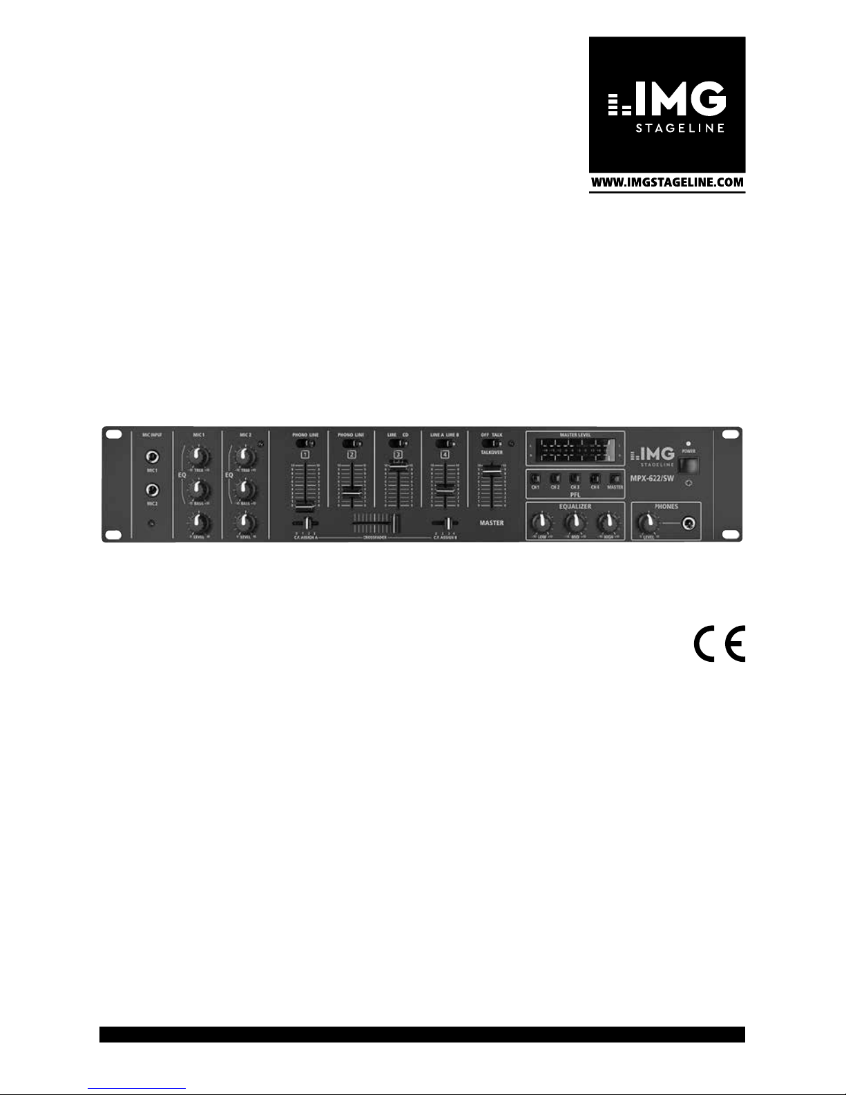
Stereo-Audio-Mischpult
Stereo Audio Mixer

ELECTRONICS FOR SPECIALISTS ELECTRONICS FOR SPECIALISTS ELECTRONICS FOR SPECIALISTS ELECTRONICS FOR SPECIALISTS
2
Deutsch ..........Seite 4
English ...........Page 7
Français ..........Page 10
Italiano...........Pagina 13
Nederlands .......Pagina 16
Español ..........Página 19
Português ........Página 22
Dansk ............Sida 25
Svenska ..........Sidan 28
Suomi............Sivulta 31
3
L
R
MIC2
MIC1
0 1 2 3
POWER
CH1
CH 2 CH 3 CH 4 MASTER
L
R
TREB
–10 +10
LEVEL
0 10
TREB
–10 +10
BASS
–10 +10
BASS
–10 +10
LEVEL
0 10
PHONO LINE
10
9
8
7
6
5
4
3
2
1
0
10
9
8
7
6
5
4
3
2
1
0
10
9
8
7
6
5
4
3
2
1
0
10
9
8
7
6
5
4
3
2
1
0
10
9
8
7
6
5
4
3
2
1
0
LINE CD
10
9
8
7
6
5
4
3
2
1
0
10
9
8
7
6
5
4
3
2
1
0
10
9
8
7
6
5
4
3
2
1
0
LINE A LINE B
10
9
8
7
6
5
4
3
2
1
0
CROSSFADER
C.F. ASSIGN A C.F. ASSIGN B
OFF TALK
10
9
8
7
6
5
4
3
2
1
0
LOW
–10 +10
MID
–10 +10
HIGH
–10 +10
LEVEL
0 10
EQUALIZER
PFL
MASTER
PHONES
MIC INPUT
MIC1 MIC 2
TALKOVER
MASTER LEVEL
EQ EQ
1
CH
2
CH
3
CH
4
CH
PHONO LINE PHONO LINE
0 2 3 4
MPX-622/SW
L
R
POWER
CH 1
CH 2 CH 3 CH 4 MASTER
L
R
10
9
8
7
6
5
4
3
2
1
0
OFF TALK
10
9
8
7
6
5
4
3
2
1
0
LOW
–10 +10
MID
–10 +10
HIGH
–10 +10
LEVEL
0 10
EQUALIZER
PFL
MASTER
PHONES
TALKOVER
MASTER LEVEL
MPX-622/SW
MIC 2
MIC 1
0 1 2 3
TREB
–10 +10
LEVEL
0 10
TREB
–10 +10
BASS
–10 +10
BASS
–10 +10
LEVEL
0 10
PHONO LINE
10
9
8
7
6
5
4
3
2
1
0
10
9
8
7
6
5
4
3
2
1
0
10
9
8
7
6
5
4
3
2
1
0
10
9
8
7
6
5
4
3
2
1
0
10
9
8
7
6
5
4
3
2
1
0
LINE CD
10
9
8
7
6
5
4
3
2
1
0
10
9
8
7
6
5
4
3
2
1
0
LINE A LINE B
10
9
8
7
6
5
4
3
2
1
0
CROSSFADER
C.F. ASSIGN A C.F. ASSIGN B
MIC INPUT
MIC 1 MIC 2
EQ EQ
1
CH
2
CH
3
CH
4
CH
PHONO LINE PHONO LINE
0 2 3 4
4
4
4
4
7
6 7
5 5
3 3 3 3
2 2
1
1
8
9
12
10
14
15
16
11
13
➊
CH1CH2CH 3CH4OUTPUT
PHONOLINELINECDAMPREC
R
L
R
L
R
L
R
L
LINELINE B LINE A PHONO
GND
230V~/ 50Hz
MAINS
CH1CH2CH3CH4OUTPUT
PHONOLINELINECDAMPREC
R
L
R
L
R
L
R
L
LINELINE B LINE A PHONO
GND
20
1918
22
17
21
➋

4
Deutsch
Stereo-Audio-Mischpult
Diese Anleitung richtet sich an Benutzer mit Grundkenntnissen in der Audiotechnik. Bitte lesen Sie die
Anleitung vor dem Betrieb gründlich durch und
heben Sie sie für ein späteres Nachlesen auf.
Auf der ausklappbaren Seite 3 finden Sie alle
beschriebenen Bedienelemente und Anschlüsse.
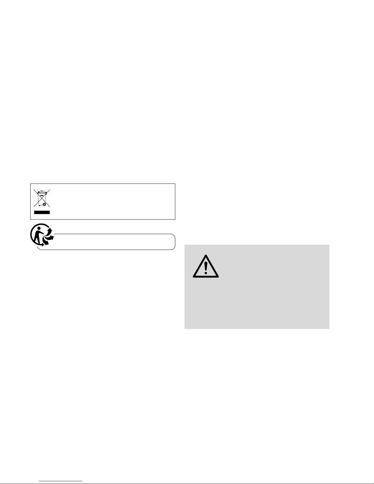
1 Übersicht der Anschlüsse und
Bedienelemente
1.1 Frontseite
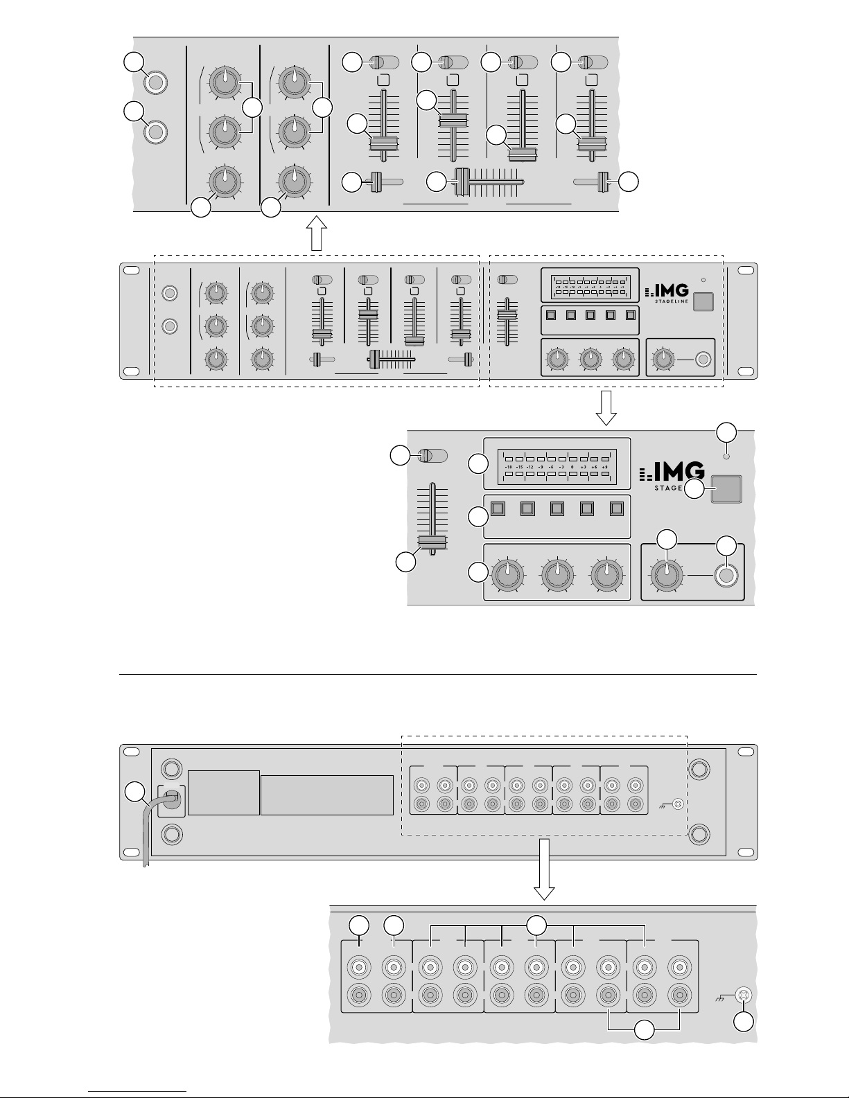
1 6,3-mm-Klinken-Eingangsbuchsen MIC 1 und
MIC 2 zum Anschluss von Mono-Mikrofonen
2 Bassregler (BASS) und Höhenregler (TREB) für
die Mikrofonkanäle MIC 1 und MIC 2
3
Eingangsumschalter für die Kanäle CH 1 – CH 4
4
Lautstärkeregler (Fader) für die Eingangskanäle
CH 1 – CH 4
5
Lautstärkeregler LEVEL für die beiden Mikrofonkanäle
6
Überblendregler (Crossfader) zum Überblenden zwischen zwei der Kanäle CH 1 – CH 4;
die jeweiligen Kanäle werden mit den beiden
C.F. ASSIGN-Schaltern (7) angewählt
7 Wahlschalter C.F. ASSIGN zum Anwählen der
zwei Ka näle, zwischen denen übergeblendet
werden soll
C.F. ASSIGN A: Position 1, 2 oder 3 zum An-
wählen des Kanals CH 1, CH 2
oder CH 3
C.F. ASSIGN B: Position 2, 3 oder 4 zum An-
wählen des Kanals CH 2, CH 3
oder CH 4
Steht der jeweilige Schalter auf Position 0, ist
kein Kanal angewählt.
8 Talkover-Schalter für Mikrofondurchsagen: In
Position TALK werden die Pegel der Kanäle
CH 1 – CH 4 um 15 dB abgesenkt.
9
Stereo-VU-Meter für den Summenausgang
AMP (19)
10
Vorhör-Tasten zum Abhören der Eingangskanäle CH 1 – CH 4 und des Summenkanals
über einen an Buchse (16) angeschlossenen
Kopfhörer
11 Ein- /Ausschalter POWER
12 Betriebsanzeige POWER
13 Summenlautstärkeregler (Fader) für den Aus-
gang AMP (19)
14
fache Klangregelung für die Ausgänge; bestehend aus Höhenregler (HIGH), Mittenregler
(MID) und Tiefenregler (LOW)
15 Lautstärkeregler LEVEL für den Kopfhörer an
Buchse (16)
16
6,3-mm-Klinkenbuchse zum Anschluss eines
Stereo-Kopfhörers (Impedanz ≥ 8 Ω)
1.2 Rückseite
17 Netzkabel zum Anschluss an 230 V/ 50 Hz
18
Ausgang REC (Cinch-Buchsen) für den Anschluss ei nes Tonaufnahmegerätes; der Aufnahmepegel ist unabhängig von der Stellung
des Summenreglers (13)
19
Summenausgang AMP (Cinch-Buchsen) für
den Anschluss eines Verstärkers
20
Eingänge LINE A, LINE B, CD und LINE
(Cinch-Buchsen) für die Kanäle CH 1 – CH 4
zum Anschluss von Geräten mit Line-Pegel
(z. B. Tuner, CD / MP3-Spieler, Kassettenrecorder)
21 Eingänge PHONO (Cinch-Buchsen) für die Ka-
näle CH 1 und CH 2 zum Anschluss von Plattenspielern mit Magnetsystem
22
Anschluss für gemeinsamen Massepunkt, z. B.
für Plattenspieler
2 Hinweise für den sicheren
Gebrauch
Das Gerät entspricht allen relevanten Richtlinien
der EU und ist deshalb mit gekennzeichnet.
WARNUNG Das Gerät wird mit lebensgefährli-
cher Netzspannung versorgt. Nehmen Sie deshalb niemals selbst
Eingriffe am Gerät vor. Durch unsachgemäßes Vorgehen besteht die
Gefahr eines elektrischen Schlages.
•
Das Gerät ist nur zur Verwendung im Innenbereich geeignet. Schützen Sie es vor Tropf- und
Spritzwasser, hoher Luftfeuchtigkeit und Hitze
(zulässiger Einsatztemperaturbereich 0 – 40 °C).
•
Stellen Sie keine mit Flüssigkeit gefüllten Ge fäße
z. B. Trinkgläser, auf das Gerät.
•
Ziehen Sie sofort den Netzstecker aus der Steckdose,
1. wenn sichtbare Schäden am Gerät oder am
Netzkabel vorhanden sind,

5
Deutsch
2. wenn nach einem Sturz oder Ähnlichem der
Verdacht auf einen Defekt besteht,
3. wenn Funktionsstörungen auftreten.
Geben Sie das Gerät in jedem Fall zur Reparatur
in eine Fachwerkstatt.
•
Ein beschädigtes Netzkabel darf nur durch eine
Fachwerkstatt ersetzt werden.
•
Ziehen Sie den Netzstecker nie am Kabel aus der
Steckdose, fassen Sie immer am Stecker an.
•
Verwenden Sie zum Reinigen nur ein trockenes,
weiches Tuch, niemals Wasser oder Chemikalien.
•
Wird das Gerät zweckentfremdet, nicht richtig
angeschlossen, falsch bedient oder nicht fachgerecht repariert, kann keine Haftung für daraus resultierende Sach- oder Personenschäden
und keine Garantie für das Gerät übernommen
werden.
Soll das Gerät endgültig aus dem Betrieb
genommen werden, übergeben Sie es zur
umweltgerechten Entsorgung einem örtlichen Recyclingbetrieb.
3 Einsatzmöglichkeiten
Das Stereo-Mischpult mit vier Stereo-Eingangskanä len und zwei Mono-Mikrofonkanälen eignet sich
so wohl für beliebige DJ-Anwendungen im professionellen oder privaten Bereich als auch für den
Einsatz in einer ELA-Anlage.
Das Mischpult kann frei aufgestellt oder in ein
Rack (482 mm / 19”) eingebaut werden. Für den
Rackeinbau wird eine Höhe von 2 HE (Höheneinheiten) = 89 mm benötigt.
4 Inbetriebnahme
1)
Die Tonquellen an die entsprechenden Eingangsbuchsen anschließen:
– LINE A, LINE B, CD und LINE (20) für den
Anschluss von Geräten mit Line-Pegel (z. B.
Tuner, CD / MP3-Spieler, Kassettenrecorder);
– PHONO (21) für den Anschluss von Platten-
spielern mit Magnetsystem;
– MIC 1 und MIC 2 (1) für den Anschluss von
Mono-Mikrofonen.
2)
Die Eingangsumschalter (3) für die Kanäle
CH 1 – CH 4 auf die entsprechende Position
stellen.
3) Den Verstärker an die Ausgangsbuchsen AMP
(19) anschließen.
4)
Für eventuelle Tonaufnahmen ein Aufnahmegerät an die Ausgangsbuchsen REC (18) anschließen. Der Aufnahmepegel ist unabhängig von
der Stellung des Summenreglers (13).
5) Den Stecker des Netzkabels (17) in eine Steckdose (230 V/ 50 Hz) stecken.
6)
Vor dem Einschalten des Mischpultes sollte
der Sum menregler (13) auf Minimum gestellt
werden, um starke Einschaltgeräusche zu vermeiden. Dann das Mischpult mit dem Schalter
POWER (11) einschalten. Zur Anzeige der Betriebsbereitschaft leuchtet die LED (12) über
dem Schalter.
7) Die angeschlossenen Geräte einschalten.
5 Bedienung
Vor der ersten Inbetriebnahme alle Klangregler (2
und 14) auf Mittelposition und den Talkover-Schalter (8) auf OFF stellen. Beide C.F. ASSIGN-Schalter
(7) auf Po sition 0 schieben (Überblendfunktion
ausge schal tet).
VORSICHT
Stellen Sie die Lautstärke der Audioanlage und die Kopfhörerlautstärke
nie sehr hoch ein. Hohe Lautstärken
können auf Dauer das Gehör schädigen! Das Ohr gewöhnt sich an
hohe Lautstärken und empfindet
sie nach einiger Zeit als nicht mehr
so hoch. Darum erhöhen Sie eine
hohe Lautstärke nach der Gewöhnung nicht weiter.
5.1 Mischen der angeschlossenen
Tonquellen
1) Mit dem Summenregler (13) wird die Gesamtlautstärke der angeschlossenen Tonquellen
eingestellt. Zur optimalen Einstellung der Eingangskanäle den Summenregler auf ca. 2⁄3 des
Maximums stellen, z. B. auf Position 7.
2) Mit den Fadern (4) die Lautstärke für die Eingangskanäle CH 1 – CH 4 einstellen. Das VUMeter (9) zeigt den Signalpegel am Summenausgang AMP (19) an. Bei 0 dB ist das Mischpult
voll ausgesteuert. Übersteuerungen zeigt das
VU-Meter durch Aufleuchten der roten LEDs an.
3)
Mit der 3fachen Klangregelung (14) das gewünsch te Klangbild für die beiden Ausgänge
REC (18) und AMP (19) einstellen: Mit den Reglern lassen sich die Tiefen (LOW), Mitten (MID)
und Höhen (HIGH) um bis zu 10 dB anheben

6
Deutsch
bzw. absenken. Stehen die Regler in Mittelstellung, findet keine Frequenzgangbeeinflussung
statt.
4)
Mit dem Crossfader (6) kann zwischen zwei
der Kanäle CH 1 – CH 4 übergeblendet werden.
Dazu mit den Schaltern C.F. ASSIGN A und B (7)
die ge wünschten Kanäle anwählen:
C.F. ASSIGN A: Position 1, 2 oder 3 zum An-
wählen des Kanals CH 1, CH 2
oder CH 3
C.F. ASSIGN B: Position 2, 3 oder 4 zum An-
wählen des Kanals CH 2, CH 3
oder CH 4
Steht der jeweilige Schalter auf Position 0, ist
kein Kanal angewählt.
Bei Aufziehen des Crossfaders nach links, wird
der mit dem Schalter C.F. ASSIGN A angewählte Kanal eingeblendet und bei Aufziehen
des Faders nach rechts der mit dem Schalter
C.F. ASSIGN B angewählte Kanal. Steht der
Fader in Mittelstellung, werden beide Kanäle
gleichzeitig auf die Ausgänge gegeben. Zum
Ausschalten der Überblendfunktion beide C.F.
ASSIGN-Schalter auf Position 0 stellen.
5.2 Vorhören der Kanäle
Über die Vorhörfunktion ist es möglich, jeden
einzelnen der Eingangskanäle CH 1 – CH 4 sowie
den Summenkanal MASTER über einen Kopfhörer
abzuhören. Der Pegel des ab gehörten Signals ist
unabhängig von der Stellung des dazugehörigen
Kanalfaders.
1)
Einen Stereo-Kopfhörer (Impedanz ≥ 8 Ω) an die
Buchse (16) an schließen.
2)
Die entsprechende Taste (10) des Kanals drücken.
3)
Mit dem Regler LEVEL (15) die gewünschte
Kopfhörerlautstärke einstellen.
5.3 Mikrofondurchsagen
1)
Für die Mikrofonkanäle MIC 1 und MIC 2 die
gewünschte Lautstärke mit den Reglern LEVEL
(5) einstellen.
2) Mit den Reglern (2) das gewünschte Klangbild
einstellen: Die Tiefen (BASS) und Höhen (TREB)
lassen sich bis zu 10 dB anheben bzw. absenken.
3)
Zur besseren Verständlichkeit einer Mikrofondurchsage können die Pegel der Kanäle
CH 1 – CH 4 um 15 dB abgesenkt werden. Dazu
den Talkover-Schal ter (8) auf Position TALK
schieben.
In Position OFF ist die Talkover-Funktion
abgeschaltet.
6 Technische Daten
Eingänge
2 × Mic:
. . . . . . . . . . . . . . . 1 mV/ 600 Ω
2 × Phono, stereo: . . . . . . . 3 mV/ 50 kΩ
6 × Line, stereo: . . . . . . . . . 150 mV/100 kΩ
Ausgänge
1 × Amp, stereo:
. . . . . . . . . 0,775 V/600 Ω
1 × Record, stereo: . . . . . . . 0,775 V/600 Ω
1 × Kopfhörer, stereo: . . . . . ≥ 8 Ω
Allgemein
Frequenzbereich:
. . . . . . . . 20 – 20 000 Hz
Klirrfaktor: . . . . . . . . . . . . . 0,1 %
Störabstand: . . . . . . . . . . . . 65 dB
Klangregelung
3 × Tiefen: . . . . . . . . . . . ±10 dB /100 Hz
1 × Mitten: . . . . . . . . . . . ±10 dB /1 kHz
3 × Höhen: . . . . . . . . . . . ±10 dB /10 kHz
Talkover: . . . . . . . . . . . . . . . –15 dB
Stromversorgung: . . . . . . . . 230 V/ 50 Hz
Leistungsaufnahme: . . . . . . 10 VA
Zulässige
Einsatztemperatur:
. . . . . . . 0 – 40 °C
Abmessungen (B × H × T): . . 482 × 89 × 95 mm,
2 HE
Gewicht: . . . . . . . . . . . . . . . 2,4 kg
Anschlüsse
Mic:
. . . . . . . . . . . . . . . . . . 2 × 6,3-mm-Klinke
Kopfhörer:
. . . . . . . . . . . . . 1 × 6,3-mm-Klinke
Alle anderen
Audioanschlüsse:
. . . . . . . . 20 × Cinch
Änderungen vorbehalten.
Diese Bedienungsanleitung ist urheberrechtlich für MONACOR ® INTERNATIONAL GmbH & Co. KG geschützt. Eine
Reproduktion für eigene kommerzielle Zwecke – auch auszugsweise – ist untersagt.
7
English
Stereo Audio Mixer
These operating instructions are intended for users
with basic knowledge in audio technology. Please
read the instructions carefully prior to operating the
unit and keep them for later reference.
All operating elements and connections de-
scribed can be found on the fold-out page 3.
1 Operating Elements
andConnections
1.1 Front panel
1
6.3 mm input jacks MIC 1 and MIC 2 to connect
mono microphones
2
Bass controls (BASS) and treble controls (TREB)
for the microphone channels MIC 1 and MIC 2
3
Input selector switches for the channels
CH 1 – CH 4
4
Volume controls (faders) for the input channels
CH 1 – CH 4
5 LEVEL controls for both microphone channels
6
Crossfader for fading between two of the
channels CH 1 – CH 4; the respective channels
are selected with the two C.F. ASSIGN switches
(7)
7 Selector switches C.F. ASSIGN to select two of
the channels for fading
C.F. ASSIGN A: position 1, 2 or 3 to select
channel CH 1, CH 2 or CH 3
C.F. ASSIGN B: position 2, 3 or 4 to select
channel CH 2, CH 3 or CH 4
If the respective switch is in 0 position, no channel is selected.
8
Talkover switch for microphone announcements: in TALK position, the levels of channels
CH 1 – CH 4 are attenuated by 15 dB.
9
Stereo VU meter for the master output AMP (19)
10
Monitoring buttons to monitor the input channels CH 1 – CH 4 and the master channel via
head phones connected to jack (16)
11 POWER switch
12 POWER LED
13 Master volume control (fader) for the output
AMP (19)
14 3-way equalizer for the outputs; consisting of
the controls HIGH, MID and LOW
15 LEVEL control for the headphones connected
to jack (16)
16
6.3 mm jack to connect stereo headphones
(impedance ≥ 8 Ω)
1.2 Rear panel
17 Mains cable for connection to 230 V/ 50 Hz
18 Output REC (RCA jacks) to connect an audio
re corder; the recording level is independent of
the position of the MASTER fader (13)
19
Master output AMP (RCA jacks) to connect
an amplifier
20
Inputs LINE A, LINE B, CD and LINE (RCA jacks)
for the channels CH 1 – CH 4 to connect units
with line level (e. g. tuner, CD / MP3 player,
cassette recorder)
21
Inputs PHONO (RCA jacks) for the channels
CH 1 and CH 2 to connect record players with
magnetic system
22
Connection for the common grounding point,
e. g. for record players
2 Safety Notes
This unit corresponds to all relevant directives of
the EU and is therefore marked with .
WARNING
The unit uses dangerous mains
voltage. Leave servicing to skilled
personnel only. Inexpert handling
may result in electric shock.
•
The unit is suitable for indoor use only. Protect
it against dripping water and splash water, high
air humidity and heat (admissible ambient temperature range 0 – 40 °C).
•
Do not place any vessels filled with liquid, e. g.
drink ing glasses, on the unit.
•
Immediately disconnect the mains plug from the
mains socket if
1. there is visible damage to the unit or to the
mains cable,
2. a defect might have occurred after the unit
was dropped or suffered a similar accident,
3. there are malfunctions.
The unit must in any case be repaired by skilled
personnel.
•
A damaged mains cable must be replaced by
skilled personnel only.
•
Never pull the mains cable to disconnect the
mains plug from the mains socket; always seize
the plug.
•
For cleaning only use a dry, soft cloth; never use
chemicals or water.
8
English
•
If the unit is used for purposes other than originally intended, if it is not correctly connected
or operated, or if it is not repaired in an expert
way, there is no liability for resulting damage to
persons or material and no guarantee for the
unit can be taken over.
•
Important for U.K. Customers!
The wires in this mains lead are coloured in
accord ance with the following code:
blue = neutral; brown = live
As the colours of the wires in the mains lead
of this appliance may not correspond with the
coloured markings identifying the terminals in
your plug, proceed as follows:
1. The wire which is coloured blue must be connected to the terminal in the plug which is
mark ed with the letter N or coloured black.
2.
The wire which is coloured brown must be
connected to the terminal which is marked
with the letter L or coloured red.
If the unit is to be put out of operation definitively, take it to a local recycling plant
for a disposal which is not harmful to the
environment.
3 Applications
The stereo mixer with four stereo input channels
and two mono microphone channels is suitable
for any desired DJ applications for professional or
private use as well as for PA system applications.
The mixer can be used as a table top unit or
be installed into a rack (482 mm / 19”). For rack
installation, two rack spaces = 89 mm are necessary.
4 Setting into Operation
1)
Connect the audio sources to the corresponding
input jacks:
– LINE A, LINE B, CD and LINE (20) to connect
units with line level (e. g. tuner, CD / MP3
player, cassette recorder);
– PHONO (21) to connect record players with
mag netic system;
– MIC 1 and MIC 2 (1) to connect mono micro-
phones.
2)
Set the input selector switches (3) for the
channels CH 1 – CH 4 to the corresponding
position.
3)
Connect the amplifier to the output jacks
AMP(19).
4)
For any audio recordings, connect a recorder to
the output jacks REC (18). The recording level
is independent of the position of the MASTER
control (13).
5) Connect the plug of the mains cable (17) to a
mains socket (230 V/ 50 Hz).
6)
Before switching on the mixer, the MASTER control (13) should be set to minimum position to
avoid a strong inrush noise. Then switch on the
mixer with the switch POWER (11). The LED (12)
above the switch lights to show that the mixer
is ready for op er ation.
7) Switch on the units connected.
5 Operation
Prior to the first setting into operation, set all
equalizer controls (2 and 14) to mid-position and
the talkover switch (8) to OFF. Set both C.F. ASSIGN switches (7) to position 0 (fading function
switched off).
CAUTION
Never adjust the audio system or
the headphones to a very high volume. Permanent high volumes may
damage your hearing! Your ear will
get accustomed to high volumes
which do not seem to be that high
after some time. Therefore, do not
further increase a high volume after
getting used to it.
5.1 Mixing the audio sources connected
1)
Use the MASTER fader (13) for adjusting the
total volume of all audio sources connected. For
optimum adjustment of the input channels, set
the MASTER fader to approx. 2⁄3 of its maximum
position, e. g. position 7.
2) With the faders (4), adjust the volume for the
input channels CH 1 – CH 4. The VU meter (9)
shows the signal level at the master output AMP
(19). At 0 dB, the mixer is set to maximum gain.
In case of overload, the red LEDs of VU meter
light up.
3) Adjust the desired tone for both outputs REC
(18) and AMP (19) with the 3-way equalizer
(14): with the controls, the LOW, MID and HIGH
frequencies may be attenuated or boosted by
up to 10 dB. In mid-position of the controls
there is no influence on the frequency response.

9
English
4) The crossfader (6) allows fading between two
of the channels CH 1 – CH 4. For this, select the
desired channels with the C.F. ASSIGN switches
A and B (7):
C.F. ASSIGN A: position 1, 2 or 3 to select
channel CH 1, CH 2 or CH 3
C.F. ASSIGN B: position 2, 3 or 4 to select
channel CH 2, CH 3 or CH 4
If the respective switch is in 0 position, no channel is selected.
When moving the crossfader to the left, the
channel selected with the C.F. ASSIGN A
switch is faded in and when moving the fader
to the right, the channel selected with the
C.F. ASSIGNB switch is faded in. If the fader is in
mid-position, both channels are fed to the outputs at the same time. To switch off the fading
function, set both C.F. ASSIGN switches to 0.
5.2 Monitoring the channels
With the monitoring function, it is possible to monitor each individual input channel CH 1 – CH 4 as
well as the MASTER channel via headphones. The
level of the signal monitored is independent of
the position of the corresponding channel fader.
1)
Connect stereo headphones (impedance ≥ 8 Ω)
to the jack (16).
2)
Press the corresponding button (10) of the
channel.
3)
Adjust the desired headphone volume with the
LEVEL control (15).
5.3 Microphone announcements
1) Adjust the desired volume with the LEVEL controls (5) for the microphone channels MIC 1
and MIC 2.
2) Adjust the desired sound with the controls (2):
the low (BASS) and high (TREB) frequencies may
be attenuated or boosted by up to 10 dB.
3) To make it easier to understand a microphone
announcement, the levels of the channels
CH 1 – CH 4 may be attenuated by 15 dB. For
this, set the talkover switch (8) to TALK position.
In OFF position, the talkover function is
switched off.
6 Specifications
Inputs
2 × mic:
. . . . . . . . . . . . . . . 1 mV/ 600 Ω
2 × phono, stereo: . . . . . . . 3 mV/ 50 kΩ
6 × line, stereo: . . . . . . . . . . 150 mV/ 100 kΩ
Outputs
1 × amp, stereo:
. . . . . . . . . 0.775 V/ 600 Ω
1 × record, stereo: . . . . . . . 0.775 V/ 600 Ω
1 × headphone, stereo: . . . . ≥ 8 Ω
General
Frequency range:
. . . . . . . . 20 – 20 000 Hz
THD: . . . . . . . . . . . . . . . . . . 0.1 %
S / N ratio: . . . . . . . . . . . . . . 65 dB
Equalizer controls
3 × low: . . . . . . . . . . . . . ±10 dB /100 Hz
1 × mid . . . . . . . . . . . . . . ±10 dB /1 kHz
3 × high . . . . . . . . . . . . . ±10 dB /10 kHz
Talkover: . . . . . . . . . . . . . . . –15 dB
Power supply: . . . . . . . . . . . 230 V/ 50 Hz
Power consumption: . . . . . . 10 VA
Admissible
ambient temperature:
. . . . . 0 – 40 °C
Dimensions (W × H × D): . . 482 × 89 × 95 mm,
2 rack spaces
Weight:
. . . . . . . . . . . . . . . 2.4 kg
Connections
Mic:
. . . . . . . . . . . . . . . . . . 2 × 6.3 mm jack
Headphones: . . . . . . . . . . . 1 × 6.3 mm jack
All other audio connections: 20 × RCA
Subject to technical modification.
All rights reserved by MONACOR ® INTERNATIONAL GmbH & Co. KG. No part of this instruction manual may be
reproduced in any form or by any means for any commercial use.

10
Français
Table de mixage audio stéréo
Cette notice s’adresse aux utilisateurs avec des
connaissances techniques de base en audio. Veuillez lire la présente notice avec attention avant le
fonctionnement et conservez-la pour pouvoir vous
y reporter ultérieurement.
Vous trouverez sur la page 3, dépliable, les
éléments et branchements décrits.
1 Eléments et branchements
1.1 Face avant
1
Prises d'entrée 6,3 mm MIC 1 et MIC 2 pour
brancher des micros mono
2 Réglages graves (BASS) et aigues (TREB) pour
les canaux micro MIC 1 et MIC 2
3
Commutateurs d'entrée pour les canaux
CH 1 – CH 4
4
Réglages de volume (fader) pour les canaux
d'entrée CH 1 – CH 4
5
Réglages de volume LEVEL pour les deux
canaux micro
6
Potentiomètre de fondu-enchaîné (crossfader)
entre deux des canaux CH 1 – CH 4. Les canaux
concernés sont à sélectionner avec les deux
commutateurs C.F. ASSIGN (7).
7
Commutateur C.F. ASSIGN : sélection des deux
canaux avec lesquels on doit effectuer un fondu-enchaîné.
C.F. ASSIGN A : Position 1, 2 ou 3 pour se-
lectionner le canal CH 1, CH 2
ou CH 3
C.F. ASSIGN B : Position 2, 3 ou 4 pour se-
lectionner le canal CH 2, CH 3
ou CH 4
Si le commutateur concerné est sur position 0,
aucun canal n'est selectionné.
8
Commutateur Talkover pour les annonces
micro : en position TALK, le niveau des canaux
CH 1 – CH 4 est abaissé de 15 dB.
9
VU-mètre stéréo pour la sortie Master AMP (19)
10
Touches de préécoute pour écouter les canaux
d'entrée CH 1 – CH 4 et le canal Master au travers de la prise (16) sur un casque
11 Interrupteur Marche /Arrêt POWER
12 Témoin de fonctionnement POWER
13
Réglage de volume Master (fader) pour la sortie
AMP(19)
14 Réglages de tonalité 3 voies pour les sorties :
aigus (HIGH), médiums (MID) et graves (LOW)
15 Réglage de volume LEVEL pour le casque sur
la prise (16)
16 Prise 6,3 mm pour brancher un casque stéréo
(im pé dance min ≥ 8 Ω)
1.2 Face arrière
17 Câble secteur 230 V/ 50 Hz
18
Sortie REC (prises RCA) pour brancher un
enregistreur ; le niveau d'enregistrement est
indépendant de la position du potentiomètre
Master(13)
19
Sortie Master AMP (prises RCA) pour brancher
un amplificateur
20
Entrées LINE A, LINE B, CD et LINE (prises RCA)
pour les canaux CH 1 – CH 4 pour brancher des
appareils à niveau Line (p. ex. tuner, lecteur
CD / MP3, ma gnéto phone)
21 Entrées PHONO (prises RCA) pour les canaux
CH 1 et CH 2 pour brancher des tourne-disques
à système magnétique
22 Branchement pour la masse commune, p. ex.
pour un tourne-disque
2 Conseils d'utilisation
etdesécurité
Cet appareil répond à toutes les directives
nécessaires de l’Union européenne et porte donc
le symbole .
AVERTISSEMENT
Cet appareil est alimenté par
une tension dangereuse. Ne
touchez jamais l’intérieur de
l’appareil car, en cas de mauvaise manipulation, vous pourriez subir une décharge électrique.
•
L’appareil n’est conçu que pour une utilisation
en intérieur. Protégez-le des éclaboussures, de
tout type de projections d’eau, de l’humidité et
de la chaleur (température ambiante admissible
0 – 40 °C).
•
En aucun cas, vous ne devez poser d’objet contenant du liquide ou un verre sur l’appareil.
•
Débranchez immédiatement la fiche du secteur
lorsque :
1. des dommages visibles apparaissent sur l’appareil ou sur le cordon secteur,
11
Français
2.
après une chute ou un cas similaire, vous avez
un doute sur l’état de l’appareil,
3. des dysfonctionnements apparaissent.
Faites toujours appel à un technicien spécialisé
pour effectuer les réparations.
•
Tout cordon secteur endommagé doit être remplacé impérativement par un technicien spécialisé.
•
Ne débranchez jamais l’appareil en tirant sur le
cordon secteur, tenez-le toujours par la fiche.
•
Pour nettoyer l’appareil, utilisez uniquement un
chiffon sec et doux, en aucun cas, de produits
chimiques ou d’eau.
•
Nous déclinons toute responsabilité en cas de
dommages corporels ou matériels résultants si
l’appareil est utilisé dans un but autre que celui
pour lequel il a été conçu, s’il n’est pas correctement branché, utilisé ou n’est pas réparé par
une personne habilitée, de même, la garantie
deviendrait caduque.
Lorsque l’appareil est définitivement retiré
du service, vous devez le déposer dans une
usine de recyclage adaptée pour contribuer à son élimination non polluante.
CARTONS ET EMBALLAGE
PAPIER À TRIER
3 Installation
Cette table de mixage stéréo avec 4 canaux stéréo
et 2 entrées micro mono a été conçu pour toutes
les utilisations DJ dans le domaine professionnel
ou privé ou dans un système de publique adresse.
La MPX-622 / SW peut être directement posée
sur une table ou installée dans un rack 482 mm
(19”) ; dans ce dernier cas, une hauteur de 2 U
(=89 mm) est nécessaire.
4 Mise en service
1)
Reliez les sources aux prises d'entrée correspondantes :
– LINE A, LINE B, CD et LINE (20) pour branche-
ment d'appareils à niveau Line (par exemple
tuner, lecteur CD / MP3, magnétophone) ;
– PHONO (21) pour brancher des tourne-disques
à système magnétique ;
– MIC 1, MIC 2 (1) pour brancher des micros
mono.
2)
Mettez les sélecteurs d'entrée (3) des canaux
CH 1 – CH 4 sur la position correspondante.
3) Connectez l’amplificateur aux prises de sortie
AMP (19).
4)
Si vous souhaitez effectuer des enregistrements,
reliez un enregistreur aux prises de sortie REC
(18). Le niveau de sortie est indépendant de la
position du réglage MASTER (13).
5)
Reliez le câble d'alimentation (17) au secteur
230 V/ 50 Hz.
6) Veillez à mettre le réglage MASTER (13) sur le
mi ni mum avant de faire fonctionner la table,
de ma nière à éviter tout bruit fort lors de l'allumage. Allumez ensuite la table avec l'interrupteur Marche /Arrêt POWER (11). La LED (12),
témoin de fonctionnement, au-dessus de l'interrupteur s'allume.
7)
Allumez maintenant les appareils reliés à la
table.
5 Utilisation
Avant la première mise en service, mettez
l'ensemble des réglages de tonalité (2 et 14)
sur la position médiane, le commutateur talkover (8) sur position OFF, les deux commutateurs
C.F. ASSIGN (7) doivent être positionnés à 0 (fonction crossfader hors service).
ATTENTION
Ne réglez pas le volume de l’installation audio et du casque trop
fort. Un volume trop élevé peut, à
long terme, générer des troubles de
l’audition. L’oreille s’habitue à des
volumes élevés et ne les perçoit plus
comme tels au bout d’un certain
temps. Nous vous conseillons donc
de régler le volume et de ne plus
le modifier.
5.1 Mixage des sources audio reliées
1)
Utilisez le potentiomètre MASTER (13) pour
régler le volume général des sources reliées.
Mettez le potentiomètre MASTER sur 2⁄3 environ
du maximum (p. ex. sur la position 7) pour régler
les canaux d'entrée de maniére optimale.
2)
Avec les potentiomètres (4) reglez le volume
pour les canaux d'entrée CH 1 – CH 4. Le niveau
de signal à la sortie Master AMP (19) est indiqué
par le VU-mètre (9). A 0 dB, le niveau maximal
est atteint. Un dépassement de niveau est signalé par les LED rouges.
3)
Avec le triple réglage de tonalité de la sortie (14),
le son souhaité peut être obtenu sur les sorties
 Loading...