

Stage Line
R
BEDIENUNGSANLEITUNG • INSTRUCTION MANUAL • MODE D`EMPLOI • ISTRUZIONI PER L´USO
GEBRUIKSAANWIJZING • HANDLEIDING • MANUAL DE INSTRUCCIONES • MANUAL DE INSTRUÇÕES
BRUGSANVISNING • BRUKSANVISNING • KÄYTTÖOHJE
STEREO-DISCO-MISCHPULT
STEREO DISCO MIXER
TABLE DE MIXAGE STÉRÉO POUR DISCOTHÈQUE
MIXER STEREO PER DISCOTECA
MPX-620 Best.-Nr. 20.0820

2
Bevor Sie einschalten ...
Wir wünschen Ihnen viel Spaß mit Ihrem
neuen img Stage Line Gerät. Dabei soll
Ihnen diese Bedienungsanleitung helfen,
alle Funktionsmöglichkeiten kennenzulernen. Die Beachtung der Anleitung vermeidet außerdem Fehlbedienungen und
schützt Sie und Ihr Gerät vor eventuellen
Schäden durch unsachgemäßen Gebrauch.
Den deutschen Text finden Sie auf den
Seiten 4
-
7.
Before you switch on ...
We wish you much pleasure with your new
img Stage Line unit. With these operating
instructions you will be able to get to know
all functions of the unit. By following these
instructions false operations will be avoided, and possible damage to you and your
unit due to improper use will be prevented.
You will find the English text on the pages
4
-
7.
Prima di accendere ...
Vi auguriamo buon divertimento con il
Vostro nuovo apparecchio img Stage Line.
Le istruzioni per l’uso Vi possono aiutare a
conoscere tutte le possibili funzioni. E rispettando quanto spiegato nelle istruzioni,
evitate di commettere degli errori, e così
proteggete Voi stessi, ma anche l’apparecchio, da eventuali rischi per uso improprio.
Il testo italiano lo potete trovare alle
pagine 8
-
11.
Avant toute mise en service ...
Nous vous remercions d’avoir choisi un
appareil img Stage Line et vous souhaitons beaucoup de plaisir à l’utiliser. Cette
notice a pour objectif de vous aider à
mieux connaître les multiples facettes de
l’appareil et à vous éviter toute mauvaise
manipulation.
La version française se trouve pages
8
-
11.
Voordat u inschakelt ...
Wij wensen u veel plezier met uw nieuw
toestel van img Stage Line. Met behulp
van bijgaande gebruiksaanwijzing kunt u
alle functiemogelijkheden leren kennen.
Door deze instructies op te volgen zal een
slechte werking vermeden worden, en zal
een eventueel letsel aan uzelf en schade
aan uw toestel tengevolge van onzorgvuldig gebruik worden voorkomen.
U vindt de nederlandstalige tekst op de
pagina’s 12
-
15.
Antes de pôr em funcionamento ...
Agradecemos-lhe por ter escolhido um
aparelho img Stage Line. Com estas
instruções ficará habilitado a conhecer e
utilizar todas as funções desta unidade.
Seguindo-as, evita possíveis manipulações defeituosas.
A versão em idioma português pode ser
encontrada nas páginas 16
-
19.
Antes de cualquier instalación
Tenemos de agradecerle el haber adquirido un equipo img Stage Line y le deseamos un agradable uso. Este manual
quiere ayudarle a conocer las multiples
facetas de este equipo y evitar cualquier
uso inadecuado.
La versión española se encuentra en las
páginas 12
-
15.
D
A
CH
GB
NL
B
F
B
CH
E
I
P
Inden De tænder for apparatet ...
Vi ønsker Dem god fornøjelse med Deres
nye img Stage Line apparat. Denne brugsanvisning giver mulighed for at lære alle
apparatets funktioner at kende. Følg vejledningen for at undgå forkert betjening og
for at beskytte Dem og Deres apparat mod
skade på grund af forkert brug.
Den danske tekst finder De på side 16
-
19.
Förskrift
Vi önskar dig mycket nöje med din nya
MPX-620. Om du först läser instruktionerna kommer du att få glädje av enheten
under lång tid. Kunskap om alla funktioner
kan bespara dig mycket besvär med
enheten i framtiden.
Du finner den svenska texten på sidan
20
-
23.
Ennen virran kytkemistä ...
Toivomme, että uusi img Stage Line-laitteesi tuo sinulle paljon iloa ja hyötyä.
Tämä käyttöohje esittää sinulle kaikki
uuden laitteesi toiminnot. Seuraamalla
sitä vältät virhetoiminnot ja niistä johtuvat
mahdolliset vahingot sinulle tai laitteellesi.
Löydät suomenkieliset käyttöohjeet sivuilta 20
-
23.
DK
S
FIN
Stage Line
R
3
LO MID HI
ON / TALKOVER
10
0
10
0
5
5
CROSSFADER
-14
0
dB
S
F
LINE
MIC
LO MID HI
PFL
0
5
10
GAIN
LO MID HI
PFL
0
5
10
GAIN
CD
MIC
X
OFF
Y
OFF
LO MID HI
PFL
0
5
10
GAIN
LINE
CD
PHONO
X
OFF
Y
OFF
LO MID HI
PFL
0
5
10
GAIN
X
OFF
Y
OFF
CD
MIC
LINE
CD
PHONO
ON
-20 10 7 5 3 1 0 1 2 3+ -20 10 7 5 3 1 0 1 2 3+dB
LEFT RIGHTLEVEL
R
01050
100
%
10
0
5
0
5
10
0
10
5
0
10
5
ASSIGN PUNCH PUNCH ASSIGN SELECT LEVEL SPEED PLAY / PAUSE
12
WRITE REPEAT
SINGLE PLAY
X
OFF
Y
OFF
START
START
START
START
MPX-620
PRO SOUND
MIXER
DJ MIC / LINE IN
CH 1 CH 2 CH 3 CH 4
+12
0
-12
+12
0
-12
+12
0
-12
+12
0
-12
+12
0
-12
+12
0
-12
+12
0
-12
+12
0
-12
+12
0
-12
+12
0
-12
+12
0
-12
+12
0
-12
+12
0
-12
+12
0
-12
+12
0
-12
10
0
5
POWER
MICDJ 1
234
ON
OFF
SAMPLER
OUTPUT
PFL
X
Y
BUS IN
MONITOR
LEVEL
X
1
2
3
4
1
2
3
4
SAMPLER CH X
RELEASE SENSITIVITY
PHONES
CH X
CH Y
LAMP
12 V / 5 W
DJ MIC
MIC / LINE IN
PFL
13 14 15 16 17 18 19 20 21 22 23 24 25
➁
FUSE 100 mAT
230 V~ / 50 Hz
OUTPUT
L
R
CH Y
CH X
CH X
REC BUS IN
CH 4
LINE
CD
PHONO
CH 3
LINE
CD
PHONO
CH 2
CD MIC
CH 1
CD MIC DJ MIC LINE
LINE IN
DCBA
START
31 32 33 34 35 36 37 38 39 40 41 42 43 44 45
12 3 45678
➀
9
10
11
12
27
30
29
26
28

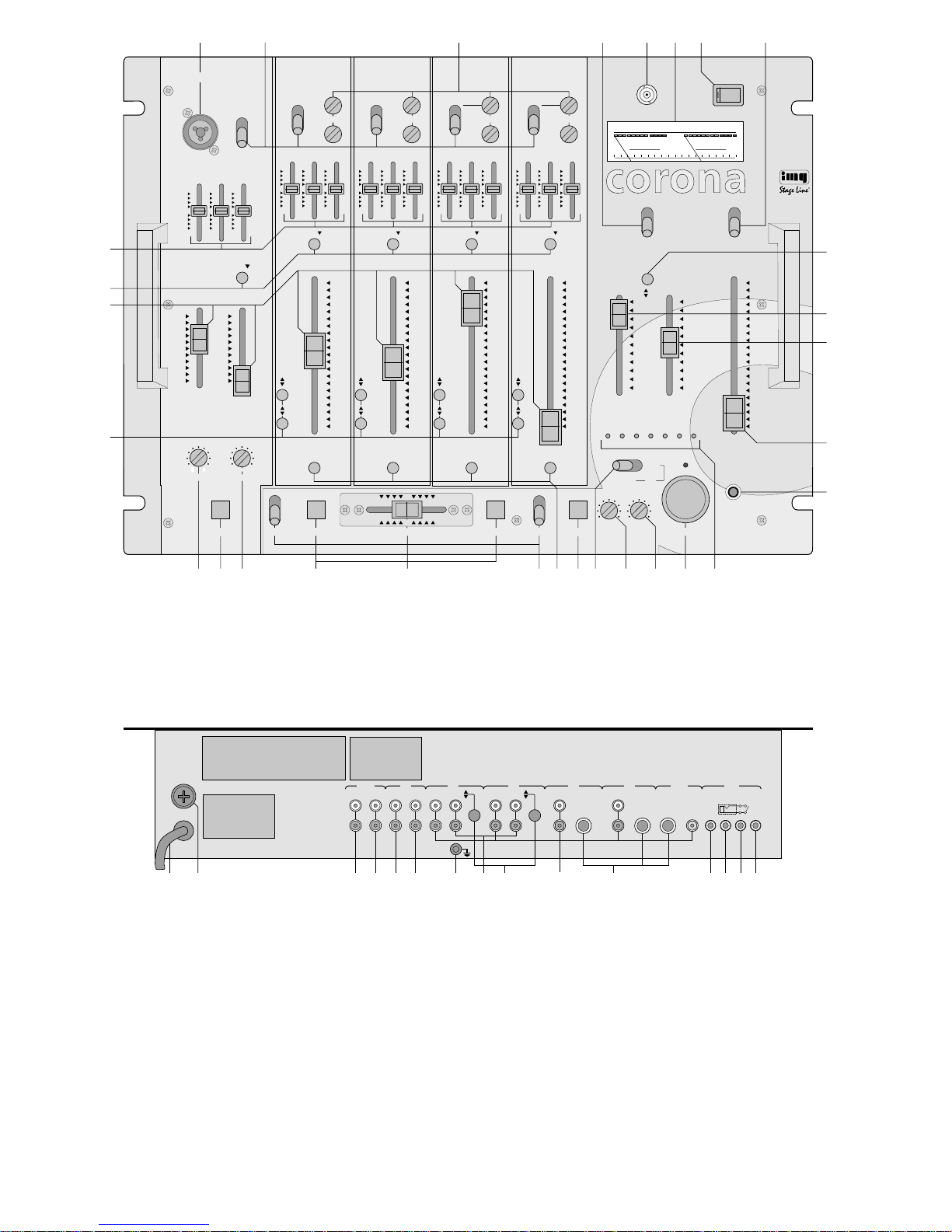
Bitte klappen Sie die Seite 3 heraus. Sie sehen
dann immer die beschriebenen Bedienelemente
und Anschlüsse.
1 Übersicht der Bedienelemente und
Anschlüsse
1.1 Frontseite
1 Eingangsbuchse (kombinierte XLR-/6,3-mm-Klin-
kenbuchse) für ein DJ-Mono-Mikrofon
2 Eingangsumschalter für den Mono-Kanal LINE
IN und die Stereo-Kanäle CH 1
-
CH 4;
LINE IN: Mono-Mikrofon (MIC)/
Mono-Line (LINE)
CH 1 und CH 2: Mono-Mikrofon (MIC)/
Stereo-Line (CD)
CH 3 und CH 4: Stereo-Line (CD) bzw. Stereo-
Phono (PHONO)/
Stereo-Line (LINE)
3 Regler GAIN zum Einstellen der Eingangsver-
stärkung für die Kanäle CH 1
-
CH 4
Die Eingangsverstärkung läßt sich für die zwei
Eingänge eines jeden Kanals getrennt einstellen:
die oberen GAIN-Regler für die Mikrofoneingänge bzw. für die Line/Phono-Eingänge, die
unteren GAIN-Regler für die Line-Eingänge.
4 Schalter BUS IN zum Ein- und Abschalten des
Erweiterungseingangs BUS IN (36)
5 BNC-Buchse LAMP zum Anschluß einer Pult-
lampe (12V/max. 5W)
6 VU-Meter
7 Ein-/Ausschalter
8 Umschalter MONITOR für den Monitorkanal und
das VU-Meter
Steht der Schalter auf Position PFL, läßt sich der
mit der Taste PFL (10) angewählte Kanal per
Kopfhörer abhören; das VU-Meter zeigt den
Pegel des jeweiligen Kanals an.
Steht der Schalter auf Position OUTPUT, kann
der mit der Taste (26) angewählte Summenkanal
abgehört werden; das VU-Meter zeigt den Aus-
gangspegel des jeweiligen Summenkanals an.
In Position SAMPLER lassen sich die mit dem
Digital-Sampler aufgenommenen Tonsignale abhören; das VU-Meter zeigt den Pegel der Tonsignale an.
9 3fache Klangregelung (Equalizer) für die Ein-
gangskanäle; bestehend aus Höhenregler (HI),
Mittenregler (MID) und Tiefenregler (LO)
10 Tasten PFL zum Abhören des jeweiligen Ein-
gangskanals über einen angeschlossenen Kopfhörer
11 Schieberegler (Fader) für die Eingangskanäle
12 Tasten zum Schalten der Kanäle CH 1
-
CH 4 auf
die beiden Summenkanäle CH X und CH Y
Sind die zwei Tasten eines Eingangskanals nicht
gedrückt, wird der Kanal auf beide Summenkanäle geschaltet. Bei gedrückter oberer Taste
wird der Kanal nicht auf den Summenkanal CH X
geschaltet, bei gedrückter unterer Taste nicht auf
den Summenkanal CH Y.
13 Regler RELEASE zum Einstellen der Wiederein-
blendungsgeschwindigkeit der Eingangskanäle
nach einer Durchsage über das DJ-Mikrofon
14 Taste ON/ TALKOVER für Mikrofon-Durchsagen
über das an Buchse (1) angeschlossene DJMikrofon; bei gedrückter Taste werden die Pegel
der übrigen Eingangskanäle um den mit dem
Regler (15) eingestellten Wert (0 dB bis
-
14dB)
abgesenkt
15 Regler SENSITIVITY zum Einstellen der Pegel-
absenkung der Eingangskanäle (0dB bis
-
14dB)
bei eingeschalteter Talkover-Funktion
16 Tasten PUNCH zum Einschalten des mit dem
Crossfader (17) ausgeblendeten Kanals
17 Überblendregler (Crossfader) zum Überblenden
zwischen zwei der Kanäle CH 1
-
CH 4
18 Schalter ASSIGN zum Anwählen der Kanäle, die
übergeblendet werden sollen
19 Tasten START zum Fernstarten der an den
Kanälen CH 1
-
CH 4 angeschlossenen Geräte
20 T aste SELECTzum Anwählen des Kanals, der mit
dem Digital-Sampler aufgenommen werden soll
21 Umschalter für die Tonaufnahme- und Wiederga-
befunktion
Position WRITE: Aufnahme des angewählten
Kanals
Position REPEAT: Endloswiedergabe der auf-
genommenen T onsignale
Position 1: einmalige Tonwiedergabe;
Rücksprung an den Anfang der
aufgenommenen Tonpassage bei
Drücken der Taste (24)
Position 2: einmalige Tonwiedergabe;
Stoppen der Tonwiedergabe bei
Drücken der Taste (24)
22 Regler LEVEL zum Einstellen der Wiedergabe-
lautstärke der aufgenommenen Tonsignale
23 Regler SPEED zum Einstellen der Aufnahmedauer
(5
-
10s) und der Wiedergabegeschwindigkeit
24 Taste PLAY/PAUSE zum Starten und Stoppen
des Digital-Samplers in Abhängigkeit des Schalters (21)
25 LED-Reihe, zeigt den zur Aufnahme angewähl-
ten Kanal an
26 Taste zum Umschalten zwischen den Stereo-
Summenkanälen
Ist die Taste nicht gedrückt, ist der Summenkanal
CH X angewählt; das VU-Meter zeigt den Ausgangspegel dieses Kanals an.
Bei gedrückter Taste ist der Summenkanal CH Y
angewählt; das VU-Meter zeigt den Ausgangspegel dieses Kanals an.
27 Schieberegler (Fader) für den Stereo-Summen-
kanal CH X
28 Schieberegler (Fader) für den Stereo-Summen-
kanal CH Y
29 Schieberegler für den Monitorkanal (Kopfhörer)
30 6,3-mm-Klinkenbuchse zum Anschluß eines
Kopfhörers (Impedanz ≥ 8Ω)
Please unfold page 3. Then you can always see
the operating elements and connections described.
1 Operating Elements and Connections
1.1 Front panel
1 Input jack (combined XLR/1/
4“jack) for a DJ
mono microphone
2 Input selector switches for the mono channel
LINE IN and the stereo channels CH 1
-
CH 4;
LINE IN: mono microphone (MIC)/
mono line (LINE)
CH 1 and CH 2: mono microphone (MIC)/
stereo line (CD)
CH 3 and CH 4: stereo line (CD) resp. stereo
phono (PHONO)/
stereo line (LINE)
3 GAIN controls for adjusting the input amplification
of channels CH 1
-
CH 4
The input amplification can be adjusted separately for both inputs of each channel: the upper
GAIN controls for the microphone inputs resp.
line/ phono inputs, the bottom GAIN controls for
the line inputs.
4 BUS IN switch for switching the extension input
BUS IN (36) on and off
5 BNC socket LAMP for connecting a gooseneck
lamp (12 V/max. 5 W)
6 VU meter
7 On/off switch
8 MONITOR selector switch for the monitor chan-
nel and the VU meter
With the switch on PFL position, the channel selected via the PFL button (10) can be monitored
with headphones; the VU meter shows the level
of the corresponding channel.
With the switch on OUTPUT position, the master
channel selected via the button (26) can be monitored; the VU meter shows the output level of the
corresponding master channel.
With the switch on SAMPLER position, the sound
signals recorded with the digital sampler can be
monitored; the VU meter shows the level of the
sound signals.
9 3-way equalizers for the input channels; con-
sisting of treble (HI), mid (MID) and bass (LO)
controls
10 PFL buttons for monitoring the corresponding
input channel via connected headphones
11 Faders for the input channels
12 Buttons for switching the channels CH 1
-
CH 4 to
both master channels CH X and CH Y
If both buttons of an input channel are not pressed,
the channel is fed to both master channels. If the
upper button is pressed, the channel is not fed to
the master channel CH X, if the bottom button is
pressed it will not be fed to the master channel
CHY.
13 RELEASE control for adjusting the speed of
fading in the input channels after an announcement via the DJ microphone
14 ON/TALKOVER button for microphone announce-
ments via the DJ microphone connected to the
jack (1); if the button is pressed, the levels of the
other input channels are attenuated by the value
(0dB up to
-
14dB) adjusted with the control (15)
15 SENSITIVITY control for adjusting the level
attenuation of the input channels (0dB up to
-
14dB) during activated talkover function
16 PUNCH buttons for switching on the channel
faded out with the crossfader (17)
17 Crossfader for fading between two of the chan-
nels CH 1
-
CH 4
18 ASSIGN switches for selecting the channels to
be faded
19 START buttons for the remote start of the units
connected to channels CH 1
-
CH 4
20 SELECTbutton for selecting the channel which is
going to be recorded with the digital sampler
21 Selector switch for the sound recording and the
reproduction function
WRITE position: recording of the selected
channel
REPEATposition: continuous reproduction of
the recorded sound signals
Position 1: one-time sound reproduction;
jumps to the beginning of the recorded sound passage if the button (24)
is pressed
Position 2: one-time sound reproduction;
the sound reproduction is stopped if
the button (24) is pressed
22 LEVEL control for adjusting the reproduction
volume of the recorded sound signals
23 SPEED control for adjusting the recording time
(5
-
10s) and the reproduction speed
24 PLAY/PAUSE button for starting and stopping the
digital sampler in dependence upon the switch
(21)
25 LED-line, indicates the channel which is selected
for recording
26 Button for selecting the stereo master channels
If the button is not pressed, the master channel
CH X is selected; the VU meter indicates the output level of this channel.
If the button is pressed, the master channel CH Y
is selected; the VU meter indicates the output
level of this channel.
27 Fader for the stereo master channel CH X
28 Fader for the stereo master channel CH Y
29 Slide control for the monitor channel (head-
phones)
30
1
/4“jack for connecting headphones
(impedance ≥ 8 Ω)
1.2 Rear panel
31 Mains cable for connecting to 230V~/50Hz
32 Mains fuse
33 Phono master output CH Y for connecting an
amplifier
4
GB
D
A
CH

1.2 Rückseite
31 Netzkabel zum Anschluß an 230V~/ 50Hz
32 Netzsicherung
33 Cinch-Summenausgang CH Y für den Anschluß
eines Verstärkers
34 Cinch-Summenausgang CH X für den Anschluß
eines Verstärkers
35 Cinch-Ausgangsbuchsen REC für den Anschluß
eines Tonaufnahmegerätes; der Aufnahmepegel
ist unabhängig von den beiden Summenreglern
(27) und (28)
36 Cinch-Eingangsbuchsen BUS IN für den An-
schluß eines zweiten Mischpultes bzw. einer weiteren Line-Quelle (Pegel nicht einstellbar)
Steht der Schalter BUS IN (4) auf Position ON,
werden die Eingangssignale dieser Buchsen auf
alle Ausgangskanäle geschaltet.
37 Anschluß für gemeinsamen Erdungspunkt, z. B
für Plattenspieler
38 Cinch-Eingangsbuchsen CD bzw. PHONO für
Kanal CH 3 und CH 4 zum Anschluß von Geräten
mit Line-Pegel (z. B. Tuner, CD-Spieler, Kassettenrecorder) oder
-
bei gedrückter Taste (39)
-
von Plattenspielern mit Magnetsystem
39 Taste zum Umschalten der Eingänge (38) von
Line- auf Phono-Pegel
40 Cinch-Eingangsbuchsen LINE bzw. CD für die
Kanäle CH 1–CH 4 und den Kanal LINE IN zum
Anschluß von Geräten mit Line-Pegel
Kanäle CH 1–CH 4: Stereo-Eingänge
Kanal LINE IN: Mono-Eingang
41 6,3-mm-Klinken-Eingangsbuchsen MIC bzw. DJ
MIC für die Kanäle CH 1, CH 2 und LINE IN zum
Anschluß von Mono-Mikrofonen
42 3,5-mm-Klinkenbuchse D zum Fernstarten des
Gerätes an Eingangskanal CH 4
43 3,5-mm-Klinkenbuchse C zum Fernstarten des
Gerätes an Eingangskanal CH 3
44 3,5-mm-Klinkenbuchse B zum Fernstarten des
Gerätes an Eingangskanal CH 2
45 3,5-mm-Klinkenbuchse A zum Fernstarten des
Gerätes an Eingangskanal CH 1
2 Hinweise für den sicheren Gebrauch
Dieses Gerät entspricht der Richtlinie für elektromagnetische Verträglichkeit 89/ 336/EWG und der
Niederspannungsrichtlinie 73/23/EWG.
Das Gerät wird mit lebensgefährlicher Netzspannung (230V~) versorgt. Nehmen Sie deshalb niemals selbst Eingriffe im Gerät vor. Durch unsachgemäßes Vorgehen besteht die Gefahr eines
elektrischen Schlages. Außerdem erlischt beim
Öffnen des Gerätes jeglicher Garantieanspruch.
Beachten Sie für den Betrieb auch unbedingt die folgenden Punkte:
•
Das Gerät ist nur zur Verwendung in Räumen
geeignet.
•
Schützen Sie das Gerät vor Feuchtigkeit und Hitze
(zulässiger Einsatztemperaturbereich 0
-
40°C).
•
Das Gerät nicht in Betrieb nehmen und sofort den
Netzstecker ziehen, wenn:
1. sichtbare Schäden am Gerät oder an der Netzanschlußleitung vorhanden sind,
2. nach einem Sturz oder ähnlichem der Verdacht
auf einen Defekt besteht,
3. Funktionsstörungen auftreten.
Das Gerät in jedem Fall zur Reparatur in eine
Fachwerkstatt geben.
•
Eine beschädigte Netzanschlußleitung darf nur
durch den Hersteller oder eine autorisierte Fachwerkstatt ersetzt werden.
•
Den Netzstecker nie an der Zuleitung aus der
Steckdose ziehen.
•
Wird das Gerät zweckentfremdet, falsch bedient
oder nicht fachgerecht repariert, kann für eventuelle Schäden keine Haftung übernommen werden.
•
Für die Reinigung nur ein trockenes Staubtuch verwenden, auf keinen Fall Chemikalien oder Wasser.
3 Aufstellmöglichkeiten
Das Stereo-Disco-Mischpult MPX-620 läßt sich
sowohl frei aufstellen als auch in ein 19“-Rack einbauen. Für den Rackeinbau wird eine Höhe von
8HE (Höheneinheiten) benötigt.
4 Inbetriebnahme
1) Die Tonquellen an die entsprechenden Eingangsbuchsen auf der Rückseite des Mischpultes anschließen:
LINE bzw. CD (40) für den Anschluß von Geräten
mit Line-Pegel (z. B Tuner, CD-Spieler, Kassettenrecorder),
Kanäle CH 1
-
CH 4: Stereo-Eingänge,
Kanal LINE IN: Mono-Eingang;
BUS IN (36) für den Anschluß eines zweiten
Mischpultes oder einer weiteren Line-Quelle
(Pegel nicht einstellbar);
CD bzw. PHONO (38) für den Anschluß von Geräten mit Line-Pegel oder
-
bei gedrückter Taste
(39)
-
von Plattenspielern mit Magnetsystem;
MIC bzw. DJ MIC (41) für den Anschluß von
Mono-Mikrofonen.
Ein DJ-Mono-Mikrofon kann an die Eingangsbuchse (1) auf der Frontseite des Gerätes angeschlossen werden.
2) Die Eingangsumschalter (2) für die Kanäle
CH 1
-
CH 4 und den Kanal LINE IN auf die ent-
sprechende Position stellen.
3) Den bzw. die Verstärker an die Ausgangsbuchsen
CH Y (33) und/oder CH X (34) anschließen.
4) Für eventuelle Tonaufnahmen ein Aufnahmegerät
an die Ausgangsbuchsen REC (35) anschließen.
Der Aufnahmepegel ist unabhängig von den beiden Summenreglern.
5) Für eine optimale Pultbeleuchtung kann an die
Buchse LAMP (5) eine Schwanenhals-Pultlampe
12V/ max. 5 W (z.B. MONACOR GNL-200, nicht
im Lieferumfang) angeschlossen werden, die mit
dem Mischpult ein- und ausgeschaltet wird.
34 Phono master output CH X for connecting an
amplifier
35 Phono output jacks REC for connecting a sound
recording unit; the recording level is independent
from both master controls (27) and (28)
36 Phono input jacks BUS IN for connecting a sec-
ond mixer resp. a further line source (level is not
adjustable)
If the BUS IN switch (4) is at position ON, the
input signals of these jacks are fed to all output
channels.
37 Connection for a common ground, e.g. with turn-
tables
38 Phono input jacks CD resp. PHONO for channel
CH 3 and CH 4 for connecting units with line level
(e.g. tuner, CD player, tape recorder) or
-
if the
button (39) is pressed
-
turntables with magnet
system
39 Button for switching the inputs (38) from line to
phono level
40 Phono input jacks LINE resp. CD for the channels
CH 1
-
CH 4 and the channel LINE IN for connecting units with line level
Channels CH 1
-
CH 4: stereo inputs
Channel LINE IN: mono input
41
1
/4“ input jacks MIC resp. DJ MIC for the channels
CH 1, CH 2, and LINE IN for connecting mono
microphones
42 3.5 mm jack D for the remote start of the unit
connected to input channel CH 4
43 3.5 mm jack C for the remote start of the unit
connected to input channel CH 3
44 3.5 mm jack B for the remote start of the unit
connected to input channel CH 2
45 3.5 mm jack A for the remote start of the unit
connected to input channel CH 1
2 Safety Notes
This appliance corresponds to the directive for electromagnetic compatibility 89/ 336 /EEC and the low
voltage directive 73/23/EEC.
This unit uses lethally high voltage (230 V~). To
prevent a shock hazard do not open the cabinet.
Leave servicing to authorized skilled personnel
only. Furthermore, any guarantee claim expires if
the unit has been opened.
Always watch the following items regarding the
operation:
•
The unit is designed for indoor use only.
•
Protect the unit against humidity and heat (permissible operating temperature range 0
-
40°C).
•
Do not take the unit into operation and immediately
take the mains plug out of the mains socket if:
1. damage at the unit or mains cable can be seen,
2. a defect might have occurred after a drop or
similar accident,
3. there are malfunctions.
The unit must in any case be repaired by authorized skilled personnel.
•
A damaged mains cable must only be repaired by
the manufacturer or authorized skilled personnel.
•
Never pull the mains plug out of the mains socket
by means of the mains cable.
•
If the unit is used for purposes other than originally
intended, if it is operated in the wrong way or not
repaired by authorized skilled personnel, there is
no liability for possible damage.
•
Use a dry dust cloth only for cleaning, by no means
chemicals or water.
•
Important for U.K. Customers!
The wires in this mains lead are coloured in accordance with the following code:
blue = neutral
brown = live
As the colours of the wires in the mains lead of this
appliance may not correspond with the coloured
markings identifying the terminals in your plug,
proceed as follows:
1.The wire which is coloured blue must be connected to the terminal in the plug which is marked
with the letter N or coloured black.
2.The wire which is coloured brown must be
connected to the terminal which is marked with the
letter L or coloured red.
3 Installation
The stereo disco mixer MPX-620 may be used as a
table top unit or may be installed in a 19” rack. A
height of 8 HE (rack spaces) is required for rack
installation.
4 Setting into Operation
1) Connect the sound sources to the corresponding
input jacks at the rear panel of the mixer:
LINE resp. CD (40) for connecting units with line
level (e.g. tuner, CD player, tape recorder),
Channels CH 1
-
CH 4: stereo inputs,
Channel LINE IN: mono input;
BUS IN (36) for connecting a second mixer or a
further line source (level not adjustable);
CD resp. PHONO (38) for connecting units with
line level or
-
if the button (39) is pressed -turn-
tables with magnet system;
MIC resp. DJ MIC (41) for connecting mono
microphones.
A DJ mono microphone can be connected to the
input jack (1) at the front panel of the unit.
2) Set the input selector switches (2) for channels
CH 1
-
CH 4 and the channel LINE IN to the cor-
responding position.
3) Connect one or two amplifiers to the output jacks
CH Y (33) and/or CH X (34).
4) Connect a recording unit to the output jacks REC
(35) if sound recordings are desired. The recording level is independent from both master controls.
5) A gooseneck console lamp with 12 V/ max. 5 W
(e.g. MONACOR GNL-200, not included) may be
5
GB
D
A
CH

6) Den Netzstecker in die Steckdose (230 V~/50Hz)
stecken.
7) Vor dem Einschalten des Mischpultes sollten die
Summenregler (27) und (28) auf Minimum gestellt
werden, um starke Einschaltgeräusche zu vermeiden. Dann das Mischpult mit dem Ein- /Ausschalter (7) einschalten.
8) Die angeschlossenen Geräte einschalten.
5 Bedienung
Vor der ersten Inbetriebnahme alle GAIN-Regler (3)
und Klangregler (9) auf Mittelposition stellen.
5.1 Mischen der angeschlossenen Tonquellen
1) Mit den Summenreglern (27) und (28) läßt sich
die Gesamtlautstärke der angeschlossenen Tonquellen einstellen. Der mit dem Summenregler
CH X (27) eingestellte Ausgangspegel steht am
Summenausgang CH X (34) zur Verfügung, der
mit dem Summenregler CH Y (28) eingestellte
Ausgangspegel wird dem Summenausgang CH Y
(33) zugeführt. Zur Pegeleinstellung der angeschlossenen Geräte die Summenregler auf ca.
2
/3
des Maximums stellen, z.B. auf Position 7.
2) Den Umschalter MONITOR (8) auf Position OUTPUT stellen. In dieser Position zeigt das VU-Meter
(6) den Ausgangspegel des Gesamtsignals an:
Ist die T aste (26) nicht gedrückt, zeigt das VU-Meter
den Ausgangspegel des Summenkanals CH X an.
Bei gedrückter Taste (26) zeigt das VU-Meter den
Ausgangspegel des Summenkanals CH Y an.
3) Mit den Fadern (11) die Pegel der Eingangskanäle einstellen. Optimale Aussteuerung liegt
vor, wenn sich die Zeiger des VU-Meters bei den
lautesten Passagen ganz rechts im grünen Bereich befinden. Übersteuerungen werden durch
ein Ausschlagen der Zeiger im roten Bereich des
VU-Meters angezeigt.
Die Fader sollten nach der Pegeleinstellung
auf ca.
2
/3 des Maximums stehen, damit beim Einund Ausblenden genügend Reglerweg vorhanden
ist. Bei wenig oder sehr weit aufgezogenen
Fadern müssen die Pegel durch Verstellen der
GAIN-Regler (3) entsprechend angepaßt werden.
Für die Kanäle CH 1
-
CH 4 sind je zwei GAINRegler vorhanden, so daß sich die Eingangsverstärkung für die zwei Eingänge eines jeden
Kanals getrennt einstellen läßt: die oberen GAINRegler für die Mikrofoneingänge bzw. für die Line/
Phono-Eingänge und die unteren GAIN-Regler
für die Line-Eingänge.
4) Mit der Klangregelung (9) das Klangbild des jeweiligen Eingangskanals einstellen. Durch Verstellen
der drei Regler lassen sich die Tiefen, Höhen und
Mitten bis zu 12dB anheben bzw. absenken. Befinden sich die Regler in der Mittelstellung findet
keine Frequenzgangbeeinflussung statt.
5) Mit dem Crossfader (17) kann zwischen zwei der
Kanäle CH 1
-
CH 4 übergeblendet werden. Dazu
mit den Schaltern ASSIGN (18) die beiden Kanäle
anwählen, zwischen denen übergeblendet werden soll. Steht der Crossfader auf Mittelposition,
werden beide Kanäle gleichzeitig auf die Ausgänge gegeben. Soll der jeweils ausgeblendete
Kanal eingeschaltet werden, die entsprechende
Taste PUNCH (16) gedrückt halten.
6) Soll das Gerät am Erweiterungeingang BUS IN
(36) zugeschaltet werden, den Schalter BUS IN
(4) auf Position ON stellen. In dieser Position wird
der Eingang BUS IN auf alle Ausgänge geschaltet. Zum Abschalten des Einganges den Schalter
BUS IN auf Postition OFF stellen.
5.2 Vorhören der Kanäle
Jede am Mischpult angeschlossene Tonquelle kann
einzeln über einen Kopfhörer abgehört werden, auch
wenn der dazugehörige Fader (11) auf Minimum
steht. Der Signalpegel der angeschlossenen Tonquelle wird auf dem VU-Meter (6) angezeigt. Die Vorhörfunktion ermöglicht somit das optimale Einstellen
der GAIN-Regler bei der Pegelanpassung. Außerdem kann durch das Abhören eines Eingangskanals
der günstigste Zeitpunkt zum Einblenden der entsprechenden Tonquelle gewählt werden.
Durch die Vorhörfunktion ist auch das Abhören eines
Summenkanals per Kopfhörer möglich. Der Signalpegel ist hier von der Stellung des jeweiligen Summenreglers abhängig. Der Ausgangspegel des mit
der Taste (26) angewählten Summenkanals wird auf
dem VU-Meter angezeigt.
Es besteht auch die Möglichkeit, die mit dem Digital-Sampler gemachten Tonaufnahmen abzuhören
(siehe auch Kap. 5.4 „Tonaufnahme und -wiedergabe mit dem Digital-Sampler“). Der Signalpegel ist
dabei nur von der Stellung des Monitor-Faders (29)
abhängig.
1) Einen Kopfhörer (≥8Ω) an die Buchse (30)
anschließen.
2) Zum Abhören eines Eingangskanals die Taste PFL
(10) des entsprechenden Eingangskanals drücken.
3) Den Umschalter MONITOR (8) auf Position PFL
stellen, wenn ein Eingangskanal abgehört wer-
den soll. In dieser Position zeigt das VU-Meter (6)
den Signalpegel des mit der Taste PFL(10) ange-
wählten Kanals an.
Den Umschalter auf Position OUTPUT stellen,
wenn ein Summenkanal abgehört werden soll.
Das VU-Meter zeigt dann den Ausgangspegel
des mit der Taste (26) angewählten Summen-
kanals an.
Zum Abhören des Digital-Samplers den Umschal-
ter auf Position SAMPLER stellen. Das VU-Meter
zeigt den Pegel des Samplers an.
4) Mit dem Fader (29) des Monitorkanals die ge-
wünschte Kopfhörer-Lautstärke einstellen.
ACHTUNG: Stellen Sie die Kopfhörerlautstärke
nie sehr hoch ein. Hohe Lautstärken können auf
Dauer das Gehör schädigen! Das menschliche
Ohr gewöhnt sich an große Lautstärken und empfindet sie nach einiger Zeit als nicht mehr so hoch.
Darum eine hohe Lautstärke nach der Gewöhnung
nicht weiter erhöhen.
5.3 Durchsagen über das DJ-Mikrofon
Ist die Taste ON/TALKOVER (14) gedrückt, werden
bei Mikrofondurchsagen über das DJ-Mikrofon an
Buchse (1) die Pegel der übrigen Eingangskanäle
connected to the LAMP jack (5) for an optimum
lighting of the mixer; the lamp is switched on and
off with the mixer.
6) Plug the mains plug into the mains socket
(230V~/50Hz).
7) The master controls (27) and (28) should be set to
minimum before turning on the mixer so that
strong inrush bump is avoided. Afterwards, turn
on the mixer with the on/off switch (7).
8) Switch on the connected units.
5 Operation
Set all GAIN controls (3) and tone controls (9) to center position before taking the unit into operation for
the first time.
5.1 Mixing of the connected sound sources
1) The total volume of the connected sound sources
can be adjusted with the master controls (27) and
(28). The output level adjusted with the master
control CH X (27) is available at the master output
CH X (34), the output level adjusted with the
master control CH Y (28) is fed to the master output CH Y (33). For the level adjustment of the
connected units set the master controls to approx.
2
/3 of the maximum, e.g. position 7.
2) Set the selector switch MONITOR (8) to the OUTPUT position. In this position, the VU meter (6)
indicates the output level of the complete signal:
If the button (26) is not pressed, the VU meter
indicates the output level of the master channel
CH X. If the button (26) is pressed, the VU meter
indicates the output level of the master channel
CH Y.
3) Adjust the levels of the input channels with the
faders (11). The optimum level is achieved if the
indicators of the VU meter are completely at the
right in the green range during the loudest passages. Overloads are indicated if the indicators
move to the red range of the VU meter.
The faders should be at approx.
2
/3 of the maxi-
mum after the level adjustment so that there is
sufficient control range for fading in and out. The
levels have to be adjusted correspondingly with
the GAIN controls (3) if the faders are almost at
minimum or maximum position. The unit is equipped with two GAIN controls for each of the
channels CH 1
-
CH 4 so that the input amplification for both inputs of each channel can be adjusted separately: the upper GAIN controls for the
microphone inputs resp. line/ phono inputs, the
bottom GAIN controls for the line inputs.
4) Adjust the sound reproduction of the corresponding input channel with the equalizer (9). The low,
high and medium frequencies can either be increased or decreased up to 12 dB by adjusting
the three controls. The frequency response is not
affected if the controls are in center position.
5) Fading between two of the channels CH 1
-
CH 4
is possible via the crossfader (17). Use the
ASSIGN switches (18) to select both channels
which are going to be faded. If the crossfader is in
center position, both channels are fed to the outputs simultaneously. Keep the corresponding
PUNCH button (16) pressed to switch on the
muted channel.
6) Turn the BUS IN switch (4) to the ON position to
switch on the unit connected to the extension
input BUS IN (36). The BUS IN input is fed to all
outputs if the switch is in this position. Set the
BUS IN switch to OFF position to switch off the
input.
5.2 Monitoring of the channels
Each sound source connected to the mixer can be
monitored separately via headphones, even if the
corresponding fader (11) is at minimum. The signal
level of the connected sound source is displayed on
the VU meter (6). With the PFL function the optimum
setting of the GAIN controls during level adjustment
is achieved. Furthermore, the best timing for fading
in the corresponding sound source can be chosen
via monitoring of an input channel.
Monitoring of a master channel is also possible by
headphones via the PFL function. The signal level
depends upon the setting of the corresponding
master control. The output level of the master channel selected with the button (26) is displayed on the
VU meter.
It is also possible to monitor the sound recordings
produced with the digital sampler (see also chapter
5.4 “Sound recording and reproduction with the digital sampler”). The signal level only depends upon the
position of the monitor fader (29).
1) Connect headphones (≥ 8Ω) to the jack (30).
2) For monitoring an input channel, press the PFL
button (10) of the corresponding input channel.
3) Adjust the selector switch MONITOR (8) to PFL
position for monitoring an input channel. In this
position the VU meter (6) indicates the signal
level of the channel selected with the PFL button
(10).
Adjust the selector switch to the OUTPUTposition
to monitor a master channel. The VU meter will
then display the output level of the master channel selected with the button (26).
Set the selector switch to the SAMPLER position
for monitoring the digital sampler. The VU meter
displays the level of the sampler.
4) Adjust the desired headphones volume with the
fader (29) of the monitor channel.
CAUTION: Do not adjust the headphones to a high
volume. Permanent high volumes may damage a
person´s hearing! The human ear gets accustomed to high volumes which do not seem to be
that high after some time. Therefore, do not further
increase a high volume after getting used to it.
5.3 Announcements via the DJ microphone
The levels of all other input channels are decreased
if the ON/TALKOVER button (14) is pressed during
microphone announcements via the DJ microphone
at jack (1). Adjust the desired level attenuation (0dB
up to
-
14 dB) with the SENSITIVITY control (15).
The speed with which the input channels are faded in
6
GB
D
A
CH
abgesenkt. Dazu mit dem Regler SENSITIVITY (15)
die gewünschte Pegelabsenkung (0 dB bis
-
14dB)
einstellen. Mit dem Regler RELEASE (13) läßt sich
die Geschwindigkeit einstellen, mit der die Eingangskanäle nach der Pegelabsenkung wieder eingeblendet werden. Durch Drehen des Reglers nach links
wird die Wiedereinblendung der Eingangskanäle
verzögert, durch Drehen nach rechts setzt die Wiedereinblendung schneller ein.
5.4 Tonaufnahme und -wiedergabe mit dem
Digital-Sampler
5.4.1 Aufnahme
1) Alle Eingangskanäle und der Summenkanal CH X
können einzeln zur Aufnahme angewählt werden.
Mit der Taste SELECT (20) den gewünschten
Kanal anwählen. Die entsprechende LED des
Kanals (25) leuchtet auf.
2) Den Umschalter (21) auf Position WRITE stellen.
3) Mit dem Regler SPEED (23) läßt sich die
gewünschte Aufnahmedauer zwischen 5 und 10
Sekunden einstellen. Je höher der Regler aufgedreht wird, desto länger wird die Aufnahme.
4) Die Taste PLAY/ PAUSE (24) drücken. Die Ton-
aufnahme beginnt. Zur Anzeige leuchtet die rote
LED über der Taste. Sie erlischt, sobald die Aufnahme beendet ist. Der Aufnahmepegel ist unabhängig von der Reglerstellung des jeweiligen
Kanals. Zum vorzeitigen Stoppen der Aufnahme
Taste PLAY/PAUSE drücken.
5.4.2 Wiedergabe
1) Für eine einmalige Wiedergabe den Umschalter
(21) auf Position 1 oder 2 stellen. Für eine Endloswiedergabe den Umschalter auf Position
REPEATstellen.
2) Zum Starten der Wiedergabe die Taste PLAY/
PAUSE (24) drücken. Die rote LED über der Taste
leuchtet auf. Die Wiedergabe ist nur über den
Summenkanal CH X möglich. Der Summenregler
CH X (27) darf nicht auf Minimum stehen. Ein
Abhören der aufgenommenen Tonsignale über
den Kopfhörer ist dagegen auch bei geschlosse-
nem Summenregler möglich (siehe Kap. 5.2 „Vorhören der Kanäle“).
3) Steht der Umschalter (21) auf Position 1, bewirkt
erneutes Drücken der Taste PLAY/PAUSE (24)
einen Rücksprung zum Anfang der aufgenommenen Tonpassage. Somit können durch schnelles Betätigen dieser Taste spezielle Toneffekte für
den Disco-Betrieb erzeugt werden. Zum Stoppen
der Wiedergabe den Umschalter (21) auf Position 2 stellen.
Steht der Umschalter (21) auf Position 2 oder
REPEAT, wird die Wiedergabe durch erneutes
Drücken der Taste PLAY/PAUSE (24) oder durch
Umstellen des Umschalters (21) auf Position 1
gestoppt. Die rote LED über der Taste erlischt.
4) Mit dem Regler LEVEL (22) die gewünschte Wiedergabelautstärke einstellen.
5) Mit dem Regler SPEED (23) kann die Geschwindigkeit der Wiedergabe verändert werden. Wird
die Reglerstellung der Aufnahme beibehalten,
läuft die Wiedergabe in der Originalgeschwindigkeit ab. Drehen des Reglers nach rechts erhöht
die Wiedergabegeschwindigkeit, Drehen des
Reglers nach links reduziert sie.
HINWEIS: Zur optimalen Anpassung der Wiedergabegeschwindigkeit sollte der Regler bei der
Aufnahme in Mittelstellung stehen. Diese Stellung
garantiert bei der Wiedergabe einen ausreichenden Reglerweg zum Erhöhen oder Herabsetzen
der Wiedergabegeschwindigkeit.
5.5 Fernstarten von Plattenspielern und CD-
Spielern
CD-Spieler bzw. Plattenspieler an den Kanälen
CH 1
-
CH 4 können über das Mischpult ferngestartet werden. Dazu muß der entsprechende Steuereingang des angeschlossenen Gerätes mit einer der
3,5-mm-Klinkenbuchsen auf der Rückseite des
Mischpultes verbunden werden:
Gerät an CH 4: Anschluß an Buchse D (42),
Gerät an CH 3: Anschluß an Buchse C (43),
Gerät an CH 2: Anschluß an Buchse B (44),
Gerät an CH 1: Anschluß an Buchse A (45).
Durch Drücken der jeweiligen START-Taste (19) wird
ein Schalter geschlossen und startet dadurch den
CD-Spieler bzw. Plattenspieler. Wird die STARTTaste wieder gelöst, öffnet der Schalter, und das
angeschlossene Gerät stoppt.
6 Technische Daten
Eingänge
MIC: . . . . . . . . . . . . . . . 4 x 2,2mV/600Ω
PHONO: . . . . . . . . . . . 2 x 2mV/47kΩ
LINE: . . . . . . . . . . . . . . 7 x 120mV/47 kΩ
BUS IN: . . . . . . . . . . . . 1 x 120mV/47 kΩ
Ausgänge
MASTER: . . . . . . . . . . . 2 x 1V/600Ω
RECORD: . . . . . . . . . . 1 x 1V/600Ω
Frequenzbereich: . . . . . . . 20
-
20000 Hz
Klirrfaktor: . . . . . . . . . . . . 0,1%
Störabstand: . . . . . . . . . . 63dB
Klangregler
5 x Tiefen: . . . . . . . . . . ±12dB/100 Hz
5 x Mitten: . . . . . . . . . . x ±12dB/1kHz
5 x Höhen: . . . . . . . . . . ±12dB/10 kHz
Sampler: . . . . . . . . . . . . . 12Bit, 5
-
10 s regelbar
Kopfhörerausgang: . . . . . ≥ 8 Ω, Stereo
Talkover: . . . . . . . . . . . . . 0dB bis -14dB
Kontaktbelastung
Fernstart . . . . . . . . . . . . . 24V /500 mA max.
Stromversorgung: . . . . . . 230V~/50Hz/15VA
Abmessungen (Bx HxT) . 482 x 120 x 348mm,
8HE
Gewicht: . . . . . . . . . . . . . . 6,5 kg
Anschlüsse
DJ-MIC: . . . . . . . . . . . . 1 x XLR/6,3-mm-Klinke
MIC: . . . . . . . . . . . . . . . 3 x 6,3-mm-Klinke, sym.
Fernstart: . . . . . . . . . . . 4 x 3,5-mm-Klinke,
massefrei
Kopfhörer: . . . . . . . . . . 1 x 6,3-mm-Klinke
alle anderen
Audioanschlüsse . . . . . 21 x Cinch
Laut Angaben des Herstellers.
Änderungen vorbehalten.
after the level attenuation is adjusted with the
RELEASE control (13). By turning the control to the
left, fading-in of the input channels is delayed, by
turning it to the right, fading-in is faster.
5.4 Sound recording and reproduction with
the digital sampler
5.4.1 Recording
1) All input channels and the master channel CH X
can be selected separately for recordings. Select
the desired channel with the SELECT button (20).
The corresponding LED (25) of the channel lights.
2) Set the selector switch (21) to WRITE position.
3) The desired recording time can be adjusted be-
tween 5 to 10 seconds with the SPEED control
(23). The more the control is turned up, the longer
the recording.
4) Press the PLAY/PAUSE button (24). The sound
recording starts. The red LED above the button
lights. It stops lighting as soon as the recording is
completed. The recording level is independent
from the control setting of the corresponding
channel. Press the PLAY/PAUSE button to stop
the recording prematurely.
5.4.2 Reproduction
1) Set the selector switch (21) to position 1 or 2 for a
one-time reproduction. Adjust the selector switch
to the REPEAT position for a continuous reproduction.
2) Press the PLAY/PAUSE button (24) for starting
the reproduction. The red LED above the button
lights. Reproduction is only possible via the
master channel CH X. The master control CH X
(27) must not be adjusted to minimum. Monitoring
of the recorded sound signals via headphones is
possible even if the master control is closed (see
chapter 5.2 “Monitoring of the Channels”).
3) If the selector switch (21) is at position 1, pressing
the PLAY/PAUSE button (24) once more will
result in a jump back to the beginning of the
recorded sound passage. Thus, if this button is
pressed quickly, special sound effects for the
disco operation can be produced. Switch the selector switch (21) to position 2 to stop the reproduction.
If the selector switch (21) is at position 2 or
REPEAT, the reproduction is stopped by pressing
the PLAY/PAUSE button (24) again or via switching the selector switch (21) to position 1. The red
LED above the button stops lighting.
4) The desired reproduction volume can be adjusted
with the LEVEL control (22).
5) The reproduction speed can be varied with the
SPEED control (23). If the control setting of the
recording is not changed, the reproduction is performed in the original speed. By turning the
control to the right, the reproduction speed is
increased, it is decreased by turning the control to
the left.
NOTE: The control should be in center position
during recordings for an optimum adaptation of
the reproduction speed. This position guarantees
sufficient control range for increasing or decreasing the reproduction speed.
5.5 Remote start of turntables and CD players
CD players resp. turntables connected to channels
CH 1
-
CH 4 can be started remotely via the mixer.
The corresponding control input of the unit must be
connected to one of the 3.5 mm jacks at the rear
panel:
Unit at CH 4: Connect to jack D (42),
Unit at CH 3: Connect to jack C (43),
Unit at CH 2: Connect to jack B (44),
Unit at CH 1: Connect to jack A(45).
By pressing the corresponding STARTbutton (19), a
switch latches and the CD player resp. the turntable
is started. If the START button is disengaged, the
switch opens and the connected unit stops.
6 Specifications
Inputs
MIC: . . . . . . . . . . . . . . . 4 x 2.2mV/600Ω
PHONO: . . . . . . . . . . . 2 x 2mV/47kΩ
LINE: . . . . . . . . . . . . . . 7 x 120mV/47 kΩ
BUS IN: . . . . . . . . . . . . 1 x 120mV/47 kΩ
Outputs
MASTER: . . . . . . . . . . . 2 x 1V/600Ω
RECORD: . . . . . . . . . . 1 x 1V/600Ω
Frequency range: . . . . . . 20
-
20000 Hz
THD: . . . . . . . . . . . . . . . . 0.1%
S/N ratio: . . . . . . . . . . . . . 63 dB
Tone control
5 x Bass: . . . . . . . . . . . . . ±12dB/100 Hz
5 x Mid: . . . . . . . . . . . . . . ±12dB/1 kHz
5 x Treble: . . . . . . . . . . . . ±12dB/10 kHz
Sampler: . . . . . . . . . . . . . 12 bit, 5
-
10 sec.
adjustable
Headphones output: . . . . ≥ 8Ω, stereo
Talkover: . . . . . . . . . . . . . 0dB up to
-
14dB
Contact rating
remote start: . . . . . . . . . . 24V /500 mA max
Power supply: . . . . . . . . . 230V~/50Hz/15VA
Dimensions (W x H x D): . 482 x 120 x 348 mm,
8HE (rack spaces)
Weight: . . . . . . . . . . . . . . . 6.5kg
Connections
DJ MIC: . . . . . . . . . . . . 1 x XLR/
1
/4“jack
MIC: . . . . . . . . . . . . . . . 3 x 1/4“jack, balanced
Remote start: . . . . . . . . 4 x 3.5mm jack, floating
Headphones: . . . . . . . . 1 x
1
/4“jack
All other
audio connections: . . . . 21 x phono
According to the manufacturer.
Subject to technical change.
7
GB
D
A
CH

Ouvrez le présent livret page 3 de manière à
visualiser les éléments et branchements.
1 Eléments et branchements
1.1 Face avant
1 Prise d'entrée (combinée XLR/jack 6,35) pour un
micro mono DJ.
2 Sélecteurs d'entrée pour le canal mono LINE IN
et les canaux stéréo CH 1–CH 4.
LINE IN: micro mono (MIC)/
Line mono (LINE)
CH 1 et CH 2: micro mono (MIC)/
stéréo Line (CD)
CH 3 et CH 4: stéréo Line (CD) ou stéréo
Phono (PHONO)/
Stéréo Line (LINE)
3 Potentiomètres GAIN: réglage de l'amplification
d'entrée des canaux CH 1–CH 4. L'amplification
d'entrée peut être réglée séparément pour les
deux entrées de chaque canal:
Potentiomètres GAIN supérieurs entrées micro/
entrées Line/Phono
Potentiomètres GAIN inférieurs entrées Line
4 Interrupteur BUS IN: marche/arrêt de l'entrée
supplémentaire BUS IN (36)
5 Prise BNC LAMP: branchement d'une lampe col
de cygne 12V/max. 5W
6 VU-mètre
7 Interrupteur Marche/Arrêt
8 Sélecteur MONITOR: pour le canal Moniteur et le
VU-mètre.
Si l'interrupteur est sur PFL, on peut effectuer
une préécoute du canal, sélectionné avec la touche PFL (10). Le VU-mètre affiche le niveau de
chaque canal.
Si l'interrupteur est sur OUTPUT, on peut faire
une préécoute du canal Master sélectionné avec
la touche (26); le VU-mètre indique son niveau de
sortie.
Sur la position SAMPLER, on peut faire une
préécoute des signaux enregistrés par le sampler
digital, le VU-mètre indique leur niveau.
9 Egaliseur 3 voies des canaux d'entrée, aigus
(Hi), médiums (MID) et graves (LO)
10 Touches PFL: préécoute du canal d'entrée avec
un casque
11 Potentiomètres à glissières des canaux d'entrée
12 Touches de commutation des canaux CH1–
CH4 sur les deux canaux Master CH X et CH Y.
Si aucune des touches n'est enfoncée, le canal
est commuté sur les deux canaux Master. Si la
touche supérieure est enfoncée, le canal n'est
pas commuté sur le canal Master CH X, si la touche inférieure est enfoncée, il n'est pas commuté
sur le canal Master CH Y.
13 Bouton RELEASE: réglage de la vitesse de
démarrage des canaux d'entrée après une
annonce via le micro DJ.
14 Touche ON/ TALKOVER pour effectuer des an-
nonces micro via le micro DJ relié à la prise (1).
Si la touche est enfoncée, les niveaux des autres
canaux d'entrée sont diminués de la valeur sélectionnée avec le potentiomètre (15) de 0dB à
-
14dB.
15 Potentiomètre SENSITIVITY: réglage de la dimi-
nution de niveau des canaux d'entrée (0 dB à
-
14dB) si la fonction Talkover est activée.
16 Touches PUNCH: mise en service du canal avec
lequel on a effectué le fondu-enchaîné (17).
17 Potentiomètre de fondu-enchaîné entre deux des
canaux CH 1–CH 4
18 Interrupteur ASSIGN: sélection des canaux avec
lesquels on doit effectuer un fondu-enchaîné.
19 Touches START: démarrage électrique des
appareils reliés aux canaux CH 1–CH 4
20 Touche SELECT: sélection du canal qui doit être
enregistré par le sampler digital.
21 Sélecteur pour les fonctions enregistrement et
lecture.
Position WRITE enregistrement du canal sé-
lectionné
Position REPEAT lecture continue des signaux
enregistrés
Position 1 lecture unique: retour au dé-
but du passage enregistré si
la touche (24) est enfoncée.
Position 2 lecture unique: arrêt de la
lecture en enfonçant la touche (24).
22 Potentiomètre LEVEL: réglage du volume de lec-
ture des signaux enregistrés
23 Potentiomètre SPEED: réglage de la durée d'en-
registrement (5–10 s) et de la vitesse de lecture.
24 Touche PLAY/PAUSE: démarrage et arrêt du
sampler digital, en fonction de la position de l'interrupteur (21)
25 Série de diodes: visualisation du canal sélec-
tionné pour l'enregistrement
26 Sélecteur des canaux Master stéréo:
Si la touche n'est pas enfoncée, le canal Master
CH X est sélectionné, le VU-mètre indique le
niveau de sortie de ce canal.
Si la touche est enfoncée, le canal Master CH Y
est sélectionné, le VU-mètre indique son niveau
de sortie.
27 Potentiomètre à glissière: canal Master stéréo
CH X
28 Potentiomètre à glissière: canal Master stéréo
CH Y
29 Potentiomètre à glissière pour le canal moniteur
(casque)
30 Prise jack 6,35: branchement d'un casque (im-
pédance ≥8 Ω)
1.2 Face arrière
31 Câble secteur 230V~/50Hz
32 Fusible secteur
33 Sortie RCA Master CH Y: pour brancher un
amplificateur
Vi consigliamo di aprire completamente la
pagina 3. Così vedrete sempre gli elementi di
comando e i collegamenti descritti.
1 Gli elementi di comando e i collega-
menti
1.1 Pannello frontale
1 Presa (combinazione XLR/ jack 6,3 mm) per mi-
crofono DJ mono
2 Commutatori per il canale mono LINE IN e per i
canali CH 1–CH 4;
LINE IN: micro mono (MIC)/
Mono Line (LINE)
CH 1 e CH 2: micro mono (MIC)/
Stereo Line (CD)
CH 3 e CH 4: Stereo Line (CD) o stereo
Phono (PHONO)/
Stereo Line (LINE)
3 Regolatori GAIN per regolare l'amplificazione
d'ingresso per i canali CH 1–CH 4.
Il guadagno può essere impostato separatamente per i due ingressi di ogni canale: con i
regolatori GAIN superiori si imposta il guadagno
degli ingressi microfono o Line/Phono, con quelli
inferiori quello degli ingressi Line.
4 Commutatore BUS IN per attivare e disattivare
l’ingresso di ampliamento BUS IN (36)
5 Presa BNC LAMP per collegare una lampada
(12V/max. 5W)
6 VU-metro
7 Interruttore ON/OFF
8 Commutatore per il canale monitor e il VU-metro
In posizione PFL, il canale selezionato con il
tasto PFL(10) può essere ascoltato nella cuffia; il
VU-metro visualizza il livello del relativo canale.
In posizione OUTPUT, il canale delle somme
selezionato con il tasto (26) può essere ascoltato;
il VU-metro visualizza il livello del relativo canale
delle somme.
In posizione SAMPLER si possono ascoltare i
segnali audio registrati dal sampler digitale; il VUmetro visualizza il livello dei segnali.
9 Regolatori toni con 3 diverse frequenze (equaliz-
zatore) per i canali d'ingresso, con regolatore
degli alti (HI), dei medi (MID) e dei bassi (LO)
10 Tasti PFL per ascoltare in cuffia il relativo canale
d'ingresso.
11 Cursore (fader) per i canali d'ingresso
12 T asti di commutazione per trasferire i canali CH1–
CH 4 sui due canali delle somme CH X e CH Y.
Con i tasti non premuti, il relativo canale viene
trasferito sui due canali delle somme. Se è premuto il tasto superiore, il canale non viene trasferito sul canale delle somme CH X, se è premuto il
tasto inferiore, il canale non viene trasferito sul
canale delle somme CH Y.
13 Regolatore RELEASE per impostare la velocità
di inserimento sfumato dei canali d’ingresso dopo
un avviso col microfono DJ.
14 Tasto ON/TALKOVER per avvisi mediante il
micro DJ collegato alla presa (1); con il tasto premuto, i livelli degli altri canali sono abbassati del
valore (da 0dB a
-
14dB) impostato con il regola-
tore (15)
15 Regolatore SENSITIVITYper regolare l’abbassa-
mento del livello dei canali d’ingresso (da 0 dB a
-
14dB) nella funzione di Talkover
16 T asti PUNCH per inserire il canale soppresso con
il crossfader (17)
17 Crossfader per il passaggio fra due dei canali
CH1–CH 4
18 Commutatore ASSIGN per selezionare i canali
previsti per il fading
19 Tasti START per l'avvio a distanza degli appa-
recchi collegati con i canali CH 1–CH 4
20 Tasto SELECT per selezionare il canale da regi-
strare con il sampler digitale
21 Selettore per la funzione di registrazione e di
riproduzione
Posizione WRITE: registrazione del canale
selezionato
Posizione REPEAT: ripetizione continua dei seg-
nali registrati
Posizione 1: riproduzione unica: ritorno
all’inizio dl brano registrato
se si preme il tasto (24)
Posizione 2: riproduzione unica: la ripro-
duzione viene fermata se si
preme il tasto (24)
22 Regolatore LEVEL per impostare il volume di
riproduzione dei segnali registrati
23 Regolatore SPEED per impostare la durata della
registrazione (5–10 sec.) e la velocità di riproduzione
24 Tasto PLAY/PAUSE per avviare e fermare il
sampler digitale a seconda della posizione del
commutatore (21)
25 Catena di led per indicare il canale selezionato
per la registrazione
26 Tasto di commutazione fra i canali stereo delle
somme
Col tasto non premuto è selezionato il canale
delle somme CH X; il VU-metro indica il livello di
quel canale.
Col tasto premuto è selezionato il canale delle
somme CH Y; il VU-metro indica il livello di quel
canale.
27 Cursore (fader) per il canale stereo delle somme
CH X
28 Cursore (fader) per il canale stereo delle somme
CH Y
29 Cursore (fader) per il canale monitor (cuffia)
30 Presa jack 6,3mm per il collegamento di una cuf-
fia (impedenza ≥8 Ω)
1.2 Pannello posteriore
31 Cavo rete 230V~/50Hz
32 Fusibile di rete
33 Uscita cinch delle somme CH Y per il collega-
mento di un amplificatore
8
I
F
B
CH

34 Sortie RCA Master CH X: pour brancher un
amplificateur
35 Prises de sortie RCA REC: branchement d'un
magnétophone: le niveau d'enregistrement est
indépendant de la position des deux potentiomètres (27) et (28).
36 Prises d'entrée RCABUS IN: branchement d'une
seconde table de mixage ou d'une autre source
Line (niveau non réglable).
Si l'interrupteur BUS IN (4) est sur ON, les signaux d'entrée de ces prises sont commutés sur
tous les canaux de sortie.
37 Branchement d'un point général à la masse, par
exemple pour une platine-disques
38 Prises d'entrée RCA CD / PHONO pour les can-
aux CH 3 et CH 4: branchement d'appareils à
niveau Line (par exemple, Tuner, Lecteur CD,
magnétophone) ou, si la touche (39) est enfoncée, de platine-disques à système magnétique.
39 Commutateur pour les entrées (38) de niveau
Line sur niveau Phono
40 Prises d'entrée RCA LINE/ CD pour les canaux
CH 1–CH 4 et le canal LINE IN pour brancher
des appareils à niveau Line
Canaux CH 1–CH 4: entrées stéréo
Canal LINE IN: entrée mono
41 Prises d'entrée jack 6,35 MIC/ DJ MIC pour les
canaux CH 1, CH 2 et LINE IN: branchements de
micros mono.
42 Prise jack 3,5 D: démarrage électrique de l'ap-
pareil relié au canal d'entrée CH 4
43 Prise jack 3,5 C: démarrage électrique de l'ap-
pareil relié au canal d'entrée CH 3
44 Prise jack 3,5 B: démarrage électrique de l'ap-
pareil relié au canal d'entrée CH 2
45 Prise jack 3,5 A: démarrage électrique de l'ap-
pareil relié au canal d'entrée CH 1
2 Conseils d'utilisation
La MPX-620 répond aux normes européennes
89/ 336 / CEE relatives à la compatibilité électromagnétique et aux normes 73/ 23/ CEE portant sur les
appareils à basse tension.
La MPX-620 est alimentée par une tension en
230 V~. Ne touchez jamais l'intérieur de l'appareil
car, en cas de mauvaise manipulation, vous pourriez
subir une décharge électrique mortelle. En outre,
l'ouverture de l'appareil rend toute garantie caduque.
Respectez les points suivants:
•
L'appareil n'est conçu que pour une utilisation en
intérieur.
•
Protégez-le de la chaleur et de l'humidité (température autorisée de fonctionnement 0–40°C)
•
Ne le faites jamais fonctionner et débranchez-le
immédiatement lorsque:
1. des dommages sur l'appareil ou le cordon secteur apparaissent,
2. après une chute …, l'appareil présente un
défaut,
3. des disfonctionnements apparaissent.
Dans tous les cas, les dommages doivent être
réparés par un technicien spécialisé.
•
Tout cordon secteur endommagé ne doit être remplacé que par le constructeur ou un technicien
habilité.
•
Ne retirez jamais le cordon secteur de la prise en
tirant dessus.
•
Nous déclinons toute responsabilité en cas de
dommage si l'appareil est utilisé dans un but autre
que celui pour lequel il a été conçu, s'il n'est pas
correctement utilisé ou réparé par une personne
habilitée.
•
Pour nettoyer l'appareil, utilisez un chiffon sec, en
aucun cas de produits chimiques ou d'eau.
3 Installation
La MPX-620 peut être directement posée sur une
table ou installée dans un rack 19"; dans ce dernier
cas, une hauteur de 8 U est nécessaire.
4 Mise en service
1) Reliez les sources aux prises d'entrée correspondantes sur la face arrière de la table:
LINE/CD (40) branchement d'appareils à niveau
LINE (par exemple, tuner, lecteur CD, magnétophone);
Canaux CH 1–CH 4: entrées stéréo
Canal LINE IN: entrée mono;
BUS IN (36) branchement d'une autre table de
mixage ou d'une autre source Line (niveau non
réglable);
CD/ PHONO (38) branchement d'appareils à niveau Line ou, si la touche (39) est enfoncée, de
platine-disques à système magnétique;
MIC/DJ MIC (41) branchement de micros mono.
On peut relier un micro mono DJ sur la prise d'en-
trée (1) située sur la face avant de l'appareil.
2) Mettez le sélecteur d'entrée (2) des canaux CH 1–
CH 4 et du canal LINE IN sur la position correspondante.
3) Connectez le /les ampli (s) aux prises de sortie
CH Y (33) et/ou CH X (34).
4) Reliez un magnétophone aux prises de sortie
REC (35). Le niveau de sortie est indépendant de
la position des deux potentiomètres Master.
5) Vous pouvez brancher une lampe col de cygne
12V/max. 5W max. (par exemple GNL-200, non
livrée) à la prise LAMP (5). Elle sera allumée et
éteinte par l'interrupteur général de la table.
6) Reliez le câble d'alimentation au secteur 230 V~/
50Hz.
7) Veillez à mettre les potentiomètres Master (27) et
(28) sur le minimum avant de faire fonctionner la
table de manière à éviter tout bruit fort lors de l'allumage. Allumez ensuite la table avec l'interrupteur Marche/Arrêt (7).
8) Allumez maintenant les divers appareils reliés à
la table.
34 Uscita cinch delle somme CH X per il collega-
mento di un amplificatore
35 Prese d'uscita cinch REC per il collegamento di
registratori; il livello di registrazione è indipendente dai due regolatori delle somme (27) e (28).
36 Prese d’ingresso cinch BUS IN per il collega-
mento di un secondo mixer o di un’altra sorgente
Line (livello non regolabile).
Se il commutatore BUS (4) è in posizione ON, i
segnali d’ingresso di queste prese passano su
tutti i canali d’uscita.
37 Collegamento di una messa a terra comune,
p.es. per un giradischi
38 Prese d'ingresso cinch CD o PHONO per i canali
CH 3 e CH 4 per collegare degli apparecchi con
livello Line (p.es. tuner, lettore CD, registratore a
cassette) oppure – con il tasto (39) premuto – dei
giradischi con sistema magnetico
39 Commutatore per gli ingressi (38) fra i livelli Line
e Phono
40 Prese d'ingresso LINE o CD per i canali CH 1–
CH 4 e per il canale LINE IN per collegare apparecchi con livello line;
Canali CH 1–CH 4: ingressi stereo
Canale LINE IN: ingresso mono
41 Prese d'ingresso jack 6,3 mm MIC e DJ MIC per
i canali CH 1, CH 2 e LINE IN per collegare dei
microfoni mono
42 Presa jack D 3,5 mm per l'avvio a distanza dell'
apparecchio collegato con il canale d'ingresso
CH 4
43 Presa jack C 3,5 mm per l'avvio a distanza dell'
apparecchio collegato con il canale d'ingresso
CH 3
44 Presa jack B 3,5 mm per l'avvio a distanza dell'
apparecchio collegato con il canale d'ingresso
CH 2
45 Presa jack A 3,5 mm per l'avvio a distanza dell'
apparecchio collegato con il canale d'ingresso
CH 1
2 Avviso di sicurezza
Questo apparecchio corrisponde alle norme 89/336/
CEE sulla compatibilità elettromagnetica e 73/ 23/
CEE per apparecchi a bassa tensione.
Questo apparecchio funziona con tensione di rete
di 230 V~. Non intervenire mai al suo interno; la
manipolazione scorretta può provocare delle scariche pericolose. Se l’apparecchio viene aperto,
cessa ogni diritto di garanzia.
Durante l’uso si devono osservare assolutamente i
seguenti punti:
•
L’apparecchio è previsto solo per l’uso all’interno
di locali.
•
Proteggere l'apparecchio dall'umidità e dal calore
(temperatura d'impiego ammessa 0–40°C).
•
Non mettere in funzione l’apparecchio e staccare
subito la spina rete se:
1. l’apparecchio o il cavo rete presentano dei
danni visibili;
2. dopo una caduta o dopo eventi simili sussiste il
sospetto di un difetto;
3. l’apparecchio non funziona correttamente.
Per la riparazione rivolgersi sempre ad una officina
competente.
•
Il cavo rete, se danneggiato, può essere sostituito
solo dal costruttore o da un laboratorio autorizzato.
•
Staccare il cavo rete afferrando la spina, senza tirare il cavo.
•
Nel caso di uso improprio, di impiego scorretto o di
riparazione non a regola d’arte non si assume
nessuna responsabilità per eventuali danni.
•
Per la pulizia usare solo un panno asciutto; non
impiegare in nessun caso prodotti chimici o acqua.
3 Possibilità di collocazione
Il mixer stereo MPX-620 per discoteca è previsto sia
per la collocazione libera che per il montaggio in un
rack 19”. Per il montaggio in rack sono richieste
8unità di altezza.
4 Messa in funzione
1) Collegare le sorgenti con le prese d'ingresso sul
retro del mixer:
LINE e CD (40) per collegare apparecchi con
livello line (p.es. tuner, lettore CD, registratore a
cassette);
Canali CH 1–CH 4: ingressi stereo
Canale LINE IN: ingresso mono;
BUS IN (36) per il collegamento di un secondo
mixer o di un’altra sorgente Line (livello non regolabile);
CD o PHONO (38) per collegare degli apparecchi
con livello Line oppure – con il tasto (39) premuto
– dei giradischi con sistema magnetico;
MIC e MIC DJ (41) per collegare dei microfoni
mono.
È possibile collegare un microfono DJ mono con
la presa d'ingresso (1) sul pannello frontale.
2) Posizionare i commutatori d’ingresso (2) per i
canali CH 1–CH 4 e per il canale LINE IN come
desiderato.
3) Collegare uno o due amplificatori alle prese d'uscita CH Y (33) e/o CH X (34).
4) Per eventuali registrazioni audio, collegare un
registratore alla presa d'uscita REC (35). Il livello
di registrazione non dipende dai due regolatori
delle somme.
5) Per illuminare il mixer è possibile collegare una
lampada a collo di cigno 12 V/max. 5 W (p. es.
MONACOR GNL-200, non compreso) alla presa
LAMP (5) che viene accesa e spenta con il mixer
6) Inserire il cavo rete nella presa (230V~/50 Hz).
7) Per evitare i rumori di commutazione, posizionare
i regolatori delle somme (27) e (28) sul minimo.
Quindi accendere il mixer con l’interruttore
ON/OFF (7).
8) Accendere gli apparecchi collegati.
9
I
F
B
CH

5 Utilisation
Avant la première mise en service, mettez l'ensemble des potentiomètres GAIN (3) et de tonalité (9) sur
la position médiane.
5.1 Mixage des sources reliées
1) Réglez le volume général des diverses sources
avec les potentiomètres Master (27) et (28). Le
niveau de sortie réglé avec le potentiomètre CH X
(27) est sur la sortie Master CH X (34), le niveau
de sortie réglé avec le potentiomètre CH Y (28),
sur la sortie Master CH Y (33). Mettez les potentiomètres sur
2
/3 environ (position 7) de leur
course pour régler le niveau des appareils reliés.
2) Mettez le sélecteur MONITOR (8) sur OUTPUT; le
VU-mètre indique le niveau de sortie du signal
général (6). Si la touche (26) n'est pas enfoncée,
le VU-mètre indique le niveau de sortie du canal
Master CH X. Si elle est enfoncée, il indique le
niveau de sortie du canal Master CH Y.
3) Réglez les niveaux des canaux d'entrée avec les
potentiomètres (11). Pour un fonctionnement optimal, lors des passages forts, l'aiguille du VUmètre doit être dans la partie verte, complètement
à droite. Toute surcharge est signalée par une
déviation de l'aiguille dans la partie rouge.
Les potentiomètres doivent, après le réglage
de niveau, être à
2
/3 environ du maximum afin que
lorsque vous effectuez un fondu-enchaîné, leur
course soit suffisante. Si les potentiomètres sont
trop ou pas assez poussés, il faut adapter les
niveaux avec les potentiomètres GAIN (3); pour
chacun des canaux CH 1–CH 4, il existe deux
réglages GAIN de telle sorte que l'amplification
pour les deux entrées de chaque canal puisse
être réglée séparément. Potentiomètre GAIN
supérieur pour les entrées micro/ Line et Phono
potentiomètre GAIN inférieur entrées Line.
4) Réglez la tonalité avec les réglages (9) pour chaque canal d'entrée. Vous pouvez ainsi augmenter
ou diminuer les graves, aigus, médiums de 12dB.
Si les potentiomètres sont en position médiane, il
n'y a aucune influence sur la bande passante.
5) Le potentiomètre (17) permet de réaliser un
fondu-enchaîné entre deux des canaux CH 1–
CH 4. Pour ce faire, sélectionnez les deux canaux
avec les interrupteurs ASSIGN (18) entre lesquels le fondu-enchaîné est effectué. Si le potentiomètre est sur la position médiane, les deux
canaux sont simultanément sur les sorties.
Enfoncez la touche PUNCH (16) correspondante
si le canal doit être allumé.
6) Pour allumer l'appareil relié aux entrées supplémentaires BUS IN (36), mettez l'interrupteur BUS
IN (4) sur la position ON: l'entrée BUS IN est commutée sur toutes les sorties. Pour les déconnecter, mettez ce commutateur sur OFF.
5.2 Préécoute des canaux
Il est possible d'effectuer une préécoute de toute
source reliée à la table de mixage via un casque,
même si le potentiomètre correspondant (11) est sur
le minimum; le niveau de la source reliée est affiché
sur le VU-mètre (6). La fonction préécoute permet un
réglage optimal des potentiomètres GAIN. En outre,
on peut ainsi déterminer le point précis à partir
duquel effectuer le fondu-enchaîné. Cette fonction
permet également la préécoute d'un canal Master
via le casque. Le niveau du signal dépend de la position du potentiomètre correspondant. Le niveau de
sortie du canal Master sélectionné avec la touche
(26) est affiché sur le VU-mètre.
Vous pouvez aussi effectuer une préécoute des
sons enregistrés par le sampler (voir paragraphe
5.4: enregistrement et lecture avec le sampler digi-
tal). Le niveau dépend uniquement de la position du
potentiomètre moniteur (29).
1) Reliez un casque (≥ 8Ω) à la prise (30).
2) Enfoncez la touche PFL (10) du canal d'entrée
correspondant.
3) Mettez le sélecteur (8) sur la position PFL lorsqu'un canal d'entrée doit être écouté. Dans cette
position, le VU-mètre (6) indique le niveau du
canal réglé avec la touche PFL (10).
Mettez le sélecteur (8) sur la position OUTPUT
pour une préécoute d'un canal Master. Dans cette
position, le VU-mètre (6) indique le niveau de sortie du canal réglé avec la touche (26).
Mettez le sélecteur sur SAMPLER pour une préécoute: le niveau est indiqué sur le VU-mètre.
4) Réglez le volume du casque, potentiomètre (29).
ATTENTION: Ne réglez pas le volume du casque
trop fort. Des volumes d'écoute trop élevés peuvent entraîner des troubles de l'audition. L'oreille
humaine s'habitue aux volumes élevés et, après
une certaine accoutumance, ne les perçoit plus
tels qu'ils sont réellement. C'est pourquoi nous
vous conseillons de ne plus augmenter le volume
une fois que vous êtes habitué à un certain
niveau sonore.
5.3 Annonces micro DJ
Si la touche ON/TALKOVER (14) est enfoncée pendant une annonce micro effectuée avec le micro DJ
(branché sur la prise (1), les niveaux des autres canaux d'entrée sont diminués. Réglez la diminution
souhaitée avec le potentiomètre SENSITIVITY (15)
(0 dB à
-
14 dB). Avec le potentiomètre RELEASE
(13), vous pouvez ajuster la vitesse à laquelle le
fondu-enchaîné des canaux d'entrée est effectué
une fois les niveaux diminués. Tournez le bouton
vers la gauche pour temporiser le fondu-enchaîné, et
vers la droite pour l'accélérer.
5.4 Enregistrement et lecture avec le sam-
pler digital
5.4.1 Enregistrement
1) Tous les canaux d'entrée et le canal Master CH X
sont sélectionnés séparément pour l'enregistrement. Choisissez le canal voulu avec la touche
SELECT (20), la diode correspondante au canal
(25) s'allume.
2) Mettez le sélecteur (21) sur la position WRITE.
5 Funzionamento
Prima della prima messa in funzione portare tutti i
regolatori GAIN (3) e dei toni (9) in posizione centrale.
5.1 Miscelare le sorgenti collegate
1) Con i regolatori delle somme (27) e (28) è possibile regolare il volume globale delle sorgenti collegate. Il livello d'uscita regolato con il regolatore
delle somme CH X (27) è disponibile all'uscita
delle somme CH X (34), mentre il livello d'uscita
regolato con il regolatore delle somme CH Y (28)
si trova all'uscita delle somme CH Y (33). Per
regolare il livello degli apparecchi collegati posizionare il regolatore delle somme a circa
2
/3 del
massimo, p.es. in posizione 7.
2) Posizionare il commutatore MONITOR (8) su
OUTPUT. In questa posizione, il VU-metro (6)
visualizza il livello d'uscita del segnale globale.
Se il tasto (26) non è premuto, il VU-metro visualizza il livello d'uscita del canale delle somme CHX.
Con il tasto (26) premuto, il VU-metro visualizza il
livello d'uscita del canale delle somme CH Y.
3) Impostare con i fader (11) i livelli dei canali d'ingresso. La regolazione è ottimale quando, con i
volumi più alti, l'indicatore del VU-metro si trova
tutto a destra nella zona verde. Se l'indicatore
passa nella zona rossa del VU-metro, il segnale è
sovrapilotato.
Dopo l'impostazione del livello, i fader dovreb-
bero trovarsi a circa
2
/3 del massimo per aver una
tolleranza sufficiente nei momenti di fading. Se i
fader sono aperti molto o aperti poco, occorre
adattare i livelli spostando i regolatori GAIN (3).
Per i canali CH 1–CH 4 sono presenti per ciascuno 2 regolatori GAIN; così il guadagno degli
ingressi può essere impostato separatamente per
i due ingressi di ogni canale: i regolatori GAIN
superiori sono previsti per gli ingressi microfono o
Phono, quelli inferiori per gli ingressi Line.
4) Impostare i toni dei diversi canali con i regolatori
(9). Spostando i tre regolatori è possibile alzare o
abbassare fino a 12dB le frequenze alte, medie e
basse. Se i cursori si trovano in posizione centrale, la frequenza non viene influenzata.
5) Con il crossfader (17) si può passare mediante
fading fra due dei canali CH 1–CH 4. Per fare ciò
selezionare i due canali con i commutatori
ASSIGN (18). Se tutti e due i canali sono destinati
alle uscite, il crossfader deve stare in posizione
centrale. Per attivare il canale soppresso tener
premuto il relativo tasto PUNCH (16).
6) Per attivare l’apparecchio collegato con gli
ingressi di ampliamento BUS IN (36) posizionare
il commutatore BUS (4) su ON. In questa posizione, gli ingressi BUS IN passano su tutte le
uscite. Per disattivare gli ingressi posizionare
BUS su OFF.
5.2 Preascolto dei canali
Con una cuffia è possibile il preascolto singolo di
tutte le sorgente collegate con il mixer, anche se il
relativo fader (11) è sul minimo. Il livello del segnale
della sorgente collegata è visualizzato sul VU-metro
(6). La funzione di preascolto permette l'impostazione ottimale dei regolatori GAIN durante l'adattamento dei livelli. Inoltre, con il preascolto del segnale
d'ingresso è possibile scegliere il momento ideale
per inserire una sorgente.
Grazie alla funzione di preascolto è possibile il
preascolto in cuffia anche di un canale delle somme.
In questo caso, il livello del segnale dipende dalla
posizione del relativo regolatore delle somme. Il
livello d'uscita del canale selezionato con il tasto (26)
è visualizzato sul VU-metro.
Esiste la possibilità di preascolto delle registra-
zioni effettuate con il sampler digitale (vedi capitolo
5.4 ”Registrazione e riproduzione con il sampler digi-
tale”). Il livello del segnale dipende in questo caso
solo dalla posizione del fader monitor (29).
1) Collegare una cuffia (≥8 Ω) con la presa (30).
2) Per ascoltare un canale d'ingresso premere il
tasto PFL (10) del relativo canale.
3) Portare il commutatore MONITOR (8) in posizione PFL per ascoltare un canale d'ingresso. In
questa posizione, il VU-metro (6) visualizza il
livello del segnale del canale selezionato con il
tasto PFL (10).
Portare il commutatore in posizione OUTPUT per
ascoltare un canale delle somme. In questa posizione, il VU-metro visualizza il livello d'uscita del
canale delle somme selezionato con il tasto (26).
Per il preascolto del sampler digitale posizionare il
commutatore su SAMPLER. Il VU-metro visualizza il livello del sampler.
4) Impostare il volume della cuffia con il fader (29)
del canale monitor.
ATTENZIONE: Mai tenere molto alto il volume
nelle cuffie. A lungo andare, il volume eccessivo
può procurare danni all’udito! L’orecchio si abitua
agli alti volumi e dopo un certo tempo non se ne
rende più conto. Non aumentare il volume successivamente.
5.3 Annuncio con il microfono DJ
Se il tasto ON/TALKOVER (14) è premuto, durante gli
annunci fatti con il microfono DJ collegato alla presa
(1), i livelli degli altri canali d’ingresso vengono abbassati. La riduzione desiderata (da 0 dB a
-
14dB)
può essere impostata con il regolatore SENSITIVITY
(15). Con il regolatore RELEASE (13) si imposta la
velocità con la quale si ripristinano il volumi dei canali
d’ingresso dopo l’abbassamento del livello. Girando il
regolatore a sinistra, il ripristino viene ritardato, girando a destra, il volume originale ritorna più velocemente.
5.4 Registrazione e riproduzione con il
sampler digitale
5.4.1 Registrazione
1) Per la registrazione si possono selezionare singo-
larmente tutti i canali d’ingresso e il canale delle
somme CH X. Il canale desiderato viene selezio-
10
I
F
B
CH

3) Réglez la durée de l'enregistrement avec le
potentiomètre SPEED (23) entre 5 et 10 secondes. Plus le potentiomètre est poussé, plus l'enregistrement est long.
4) Enfoncez la touche PLAY/PAUSE (24), l'enregistrement commence. La diode rouge au dessus de
la touche s'allume, elle s'éteint dès que l'enregistrement est terminé. Le niveau d'enregistrement
est indépendant de la position des réglages de
chaque canal. Pour arrêter l'enregistrement avant
son terme, enfoncez la touche PLAY/PAUSE.
5.4.2 Lecture
1) Mettez le sélecteur (21) sur la position 1 ou 2 pour
une lecture unique; pour une lecture en continu,
mettez-le sur la position REPEAT.
2) Pour démarrer la lecture, enfoncez la touche
PLAY/ PAUSE (24), la diode rouge au-dessus de
la touche s'allume. La lecture n'est possible que
sur le canal Master CH X. Le potentiomètre CH X
(27) ne doit pas être sur le minimum. Il est possible d'effectuer une préécoute des signaux enregistrés avec un casque même si le potentiomètre est fermé (voir paragraphe 5.2 Préécoute
des canaux).
3) Si le sélecteur (21) est sur la position 1, une nouvelle pression sur la touche PLAY/PAUSE (24)
permet de revenir en arrière au début du passage
enregistré. En enfonçant cette touche rapidement, vous pouvez ainsi produire des effets spéciaux pour une utilisation en discothèque. Pour
arrêter la lecture, mettez le sélecteur (21) sur la
position 2.
Si ce sélecteur (21) est sur la position 2 ou
REPEAT, la lecture est arrêtée par une nouvelle
pression sur la touche PLAY/PAUSE (24) ou en
mettant le sélecteur (21) sur la position 1. La
diode rouge s'éteint.
4) Réglez le volume de la lecture avec le potentiomètre LEVEL (22).
5) Vous pouvez modifier la vitesse de lecture avec le
réglage SPEED (23); si vous conservez la position de l'enregistrement, la lecture se fera à la
vitesse d'origine. Si vous tournez le potentiomètre
vers la droite, vous augmentez la vitesse, si vous
le tournez vers la gauche, vous la diminuez.
CONSEIL: Pour une adaptation optimale de la
vitesse de lecture, nous vous conseillons de
mettre le potentiomètre, lors de l'enregistrement,
sur la position médiane. Ainsi, lors de la lecture, la
course est assez longue pour augmenter ou diminuer correctement la vitesse.
5.5 Démarrage électrique de platine-disques
ou lecteurs CD
Vous pouvez faire démarrer un lecteur CD ou une
platine-disques, reliés aux canaux CH 1–CH 4, depuis la table. Pour ce faire, reliez l'entrée de l'appareil à une des prises jack 3,5 situées sur la face
arrière de la table de mixage.
Appareil relié à CH 4: branchement à la prise D (42),
appareil relié à CH 3: branchement à la prise C (43),
appareil relié à CH 2: branchement à la prise B (44),
appareil relié à CH 1: branchement à la prise A(45).
Si vous enfoncez la touche START(19), un interrupteur est fermé et démarre ainsi le lecteur CD ou la
platine-disques. Si la touche est relâchée, l'interrupteur s'ouvre, l'appareil s'arrête.
6 Caractéristiques techniques
Entrées
MIC: . . . . . . . . . . . . . . . 4 x 2,2mV/600Ω
PHONO: . . . . . . . . . . . 2 x 2mV/47kΩ
LINE : . . . . . . . . . . . . . . 7 x 120mV/47kΩ
BUS IN: . . . . . . . . . . . . 1 x 120mV/47 kΩ
Sorties
MASTER: . . . . . . . . . . . 2 x 1 V/600 Ω
RECORD: . . . . . . . . . . 1 x 1 V/600 Ω
Bande passante: . . . . . . . 20–20000 Hz
Taux de distorsion: . . . . . . 0,1 %
Rapport signal/bruit: . . . . 63dB
Réglage de tonalités
5 x Graves: . . . . . . . . . ±12dB/100Hz
5 x Médiums: . . . . . . . . ±12dB/1 kHz
5 x Aigus: . . . . . . . . . . . ±12dB/10kHz
Sampler: . . . . . . . . . . . . . 12 bits, 5–10 secondes,
réglable
Sortie casque: . . . . . . . . . ≥ 8Ω, stéréo
Talkover: . . . . . . . . . . . . . 0dB à
-
14dB
Démarrage électrique: . . . 24V /500 mA max.
Alimentation: . . . . . . . . . . 230V~/50Hz/15VA
Dimensions (L x H x P): . . 482 x 120 x 348mm,
8U
Poids: . . . . . . . . . . . . . . . . 6,5kg
Branchements
DJ-MIC: . . . . . . . . . . . . 1 x XLR/jack 6,35
MIC: . . . . . . . . . . . . . . . 3 x jack 6,35 sym
Démarrage électrique: . 4 x jack 3,5, non relié
Casque: . . . . . . . . . . . . 1 x jack 6,35
Autres
branchements audio: . . 21 x RCA
D'après les données du constructeur.
Tout droit de modification réservé.
nato con il tasto SELECT (20) e si accende il led
del canale (25).
2) Posizionare il commutatore (21) su WRITE.
3) Con il regolatore SPEED (23), la durata della registrazione può essere impostata fra 5 e 10
secondi. Più si apre il regolatore, più lunga
diventa la registrazione.
4) Premere il tasto PLAY/PAUSE (24). La registrazione inizia e si accende il led rosso sopra il tasto.
Il led si spegne quando la registrazione è terminata. Il livello di registrazione non dipende dalla
posizione del regolatore del canale. Per interrompere la registrazione si può premere il tasto
PLAY/PAUSE.
5.4.2 Riproduzione
1) Per una riproduzione unica posizionare il commutatore (21) su 1 o 2. Per la riproduzione senza fine
portarlo su REPEAT.
2) Per avviare la riproduzione premere i tasti
PLAY/PAUSE (24). Il led rosso sopra il tasto si
accende. La riproduzione è possibile solo con il
canale delle somme CH X. Il regolatore del
canale delle somme CH X (27) non deve trovarsi
sul minimo. Il preascolto in cuffia è comunque
possibile anche con il regolatore delle somme chiuso (vedi capitolo 5.2 ”Preascolto dei canali”).
3) Se il commutatore (21) si trova in posizione 1, una
nuova pressione sul tasto PLAY/PAUSE (24) provoca il ritorno all’inizio del brano registrato. Premendo velocemente questo tasto, si possono
produrre effetti speciali. Per fermare la riproduzione portare il commutatore (21) in posizione 2.
Se il commutatore (21) si trova in posizione 2 o
REPEAT, la riproduzione viene fermata con una
nuova pressione sul tasto PLAY/PAUSE (24)
oppure con lo spostamento del commutatore (21)
in posizione 1. Aquesto punto il led rosso sopra il
tasto si spegne.
4) Con il regolatore LEVEL (22) si imposta il volume
desiderato della riproduzione.
5) Con il regolatore SPEED (23) si può modificare la
velocità della riproduzione. Se si mantiene la
stessa posizione della registrazione, la riproduzione avviene con la velocità originale. Girando il
regolatore a destra, la velocità aumenta, girandolo a sinistra, la velocità diminuisce.
NOTA: Per permettere un adattamento ottimale
della velocità di riproduzione, il regolatore dovrebbe trovarsi in posizione centrale durante la
registrazione. Tale posizione lascia sufficiente
spazio per aumentare o per ridurre la velocità
durante la riproduzione.
5.5 Avvio a distanza di giradischi e lettori CD
È possibile avviare dal mixer dei lettori CD e dei giradischi collegati con i canali CH 1–CH 4. In tal caso
occorre collegare l'ingresso di comando dell'apparecchio con una delle prese jack 3,5mm che si trovano sul retro del mixer.
Collegare l’apparecchio a CH 4: presa D (42),
collegare l’apparecchio a CH 3: presa C (43),
collegare l’apparecchio a CH 2: presa B (44),
collegare l’apparecchio a CH 1: presa A(45).
Premendo il relativo tasto START (19) si chiude un
interruttore provocando l'avvio del lettore CD o del
giradischi. Se si libera di nuovo il tasto START, l'interruttore si apre, e l'apparecchio collegato si ferma.
6 Dati tecnici
Ingressi
MIC: . . . . . . . . . . . . . . . 4 x 2,2mV/600Ω
PHONO : . . . . . . . . . . . 2 x 2mV/47 kΩ
LINE : . . . . . . . . . . . . . . 7 x 120mV/47 kΩ
BUS IN: . . . . . . . . . . . . 1 x 120mV/47 kΩ
Uscite
MASTER: . . . . . . . . . . . 2 x 1V/600Ω
RECORD: . . . . . . . . . . 1 x 1V/600Ω
Banda passante: . . . . . . . 20–20000 Hz
Fattore di distorsione: . . . 0,1%
Rapporto S/R: . . . . . . . . . 63dB
Regolatore toni
5 x Bassi: . . . . . . . . . . . ±12dB/100Hz
5 x Medi: . . . . . . . . . . . ±12dB/1 kHz
5 x Alti: . . . . . . . . . . . . . ±12dB/10kHz
Sampler: . . . . . . . . . . . . . 12 bit, 5–10 sec.
regolabili
Uscita cuffia: . . . . . . . . . . ≥8 Ω, stereo
Talkover: . . . . . . . . . . . . . da 0dB a
-
14dB
Potenza contatti
avvio a distanza . . . . . . . . 24V /500 mAmax
Alimentazione: . . . . . . . . . 230V~/50 Hz/15 VA
Dimensioni (lxhxp): . . . . . 482 x 120 x 348mm,
8 unità di altezza
Peso: . . . . . . . . . . . . . . . . 6,5kg
Collegamenti
MIC DJ . . . . . . . . . . . . . 1 x XLR/jack 6,3 mm
MIC . . . . . . . . . . . . . . . 3 x jack 6,3mm, simm.
Avvio a distanza . . . . . 4 x jack 3,5mm,
senza massa
Cuffia . . . . . . . . . . . . . . 1 x jack 6,3 mm
Tutti gli altri
collegamenti audio: . . . 21 x cinch
Dati forniti dal costruttore.
Con riserva di modifiche tecniche.
11
I
F
B
CH

Vouw bladzijde 3 helemaal open, zodat u steeds
een overzicht hebt van de beschreven bedieningselementen en de aansluitingen.
1 Overzicht van de bedieningselemen-
ten en aansluitingen
1.1 Frontpaneel
1 Ingang (gecombineerde XLR-/6,3-mm-jack) voor
een DJ monomicrofoon
2 Ingangsschakelaars voor het monokanaal LINE
IN en de stereokanalen CH 1 tot CH 4;
LINE IN: monomicrofoon (MIC)/
monolijn (LINE)
CH 1 en CH 2: monomicrofoon (MIC)/
stereolijn (CD)
CH 3 en CH 4: stereo-phono (PHONO)/
stereolijn (LINE)
3 GAIN-regelaar voor regeling van de ingangsver-
sterking van de kanalen CH 1 tot CH 4
De ingangsversterking kan voor beide ingangen
van elk kanaal afzonderlijk geregeld worden: de
bovenste GAIN-regelaars voor de microfoonresp. lijn-/phono-ingangen, de onderste volumeregelaars voor de lijningangen.
4 BUS IN-schakelaar om de ingang BUS IN (36) in
en uit te schakelen.
5 BNC-connector voor aansluiting van een zwa-
nenhalslamp (12V/max. 5W)
6 VU-meter
7 POWER-schakelaar
8 MONITOR-keuzeschakelaar voor het monitorka-
naal en de VU-meter
Met de schakelaar in de PFL-stand kan het kanaal dat met behulp van de PFL-toets (10) geselecteerd is, via een hoofdtelefoon voorbeluisterd
worden; de VU-meter geeft het niveau van het
desbetreffende kanaal weer.
Met de schakelaar in OUTPUT-stand kan het
masterkanaal dat met behulp van de toets (26)
geselecteerd is, voorbeluisterd worden; de VUmeter geeft het uitgangsniveau van het overeenkomstige kanaal weer.
Met de schakelaar in SAMPLER-positie kunnen
de geluidssignalen die met de digitale sampler
opgenomen werden, voorbeluisterd worden; de
VU-meter geeft het uitgangsniveau van de
geluidssignalen weer.
9 3-bands equalizers voor de ingangskanalen met
regeling van hoge (HI) en lage (LO) tonen en
middentonen (MID)
10 PFL-toetsen voor de voorafluistering van het
overeenkomstige ingangskanaal via een aangesloten hoofdtelefoon
11 Schuifregelaars voor de ingangskanalen
12 Toetsen om de kanalen CH 1 tot CH 4 naar beide
masterkanalen CH X en CH Y te schakelen.
Indien de beide toetsen van een ingangskanaal
niet ingedrukt worden, dan gaat het kanaalsignaal naar de beide masterkanalen.
Indien de bovenste toets ingedrukt wordt, gaat het
kanaalsignaal niet naar het masterkanaal CH X,
indien de onderste toets ingedrukt wordt, gaat het
kanaalsignaal niet naar het masterkanaal CH Y.
13 RELEASE-regelaar om de snelheid te regelen,
waarmee de ingangskanalen na een aankondiging via de DJ-microfoon weer ingemixt worden.
14 ON/ TALKOVER-toets voor aankondigingen via
de DJ-microfoon, aangesloten op jack (1); bij
drukken op deze toets worden de niveaus van de
andere ingangskanalen via de regelaar (15) met
een waarde tussen 0 en
-
14dB gedempt.
15 SENSITIVITY-regelaar voor regeling van het
dempingsniveau van de ingangskanalen (0dB tot
maximaal
-
14 dB) tijdens de geactiveerde talk-
over-functie.
16 PUNCH-toetsen om naar het kanaal te schakelen
dat met de crossfader (17) weggemixt wordt.
17 Crossfader om te regelen tussen twee van de
kanalen CH 1 tot CH 4.
18 ASSIGN-schakelaars voor selectie van de te
mixen kanalen.
19 START-toetsen voor de faderstart van de compo-
nenten die aangesloten zijn op kanaal CH 1 tot CH4
20 SELECT-toets voor de selectie van het kanaal dat
met de digitale sampler opgenomen moet worden.
21 Keuzeschakelaar voor de geluidsopnames en de
weergavefunctie
WRITE-stand: opname van het geselecteerde
kanaal
REPEAT-stand: continue weergave van de
opgenomen geluidssignalen
Stand 1: eenmalige geluidsweergave;
springt naar het begin van de
opgenomen passage bij het
drukken op toets (24)
Stand 2: eenmalige geluidsweergave;
de geluidsweergave wordt
onderbroken bij het drukken op
toets (24)
22 LEVEL-regelaar voor de regeling van het weer-
gavevolume van de opgenomen geluidssignalen
23 SPEED-regelaar voor de regeling van de opna-
metijd (5–10 seconden) en de weergavesnelheid
24 PLAY/PAUSE-toets om de digitale sampler te
starten en te stoppen, al naar gelang de stand
van schakelaar (21)
25 LED-lijn om het kanaal dat voor opname geselec-
teerd is, aan te duiden.
26 Toets om de stereo-masterkanalen te selecteren
Indien de toets niet ingedrukt is, wordt het
masterkanaal CH X geselecteerd; de VU-meter
geeft het uitgangsniveau van dit kanaal aan.
Indien de toets ingedrukt is, wordt het masterkanaal CH Y geselecteerd; de VU-meter geeft het
uitgangsniveau van dit kanaal aan.
27
Schuifregelaar voor het stereo-masterkanaal CHX
28 Schuifregelaar voor het stereo-masterkanaal CH Y
29 Schuifregelaar voor het monitorkanaal (hoofdte-
lefoon)
30 6,3 mm-jack voor aansluiting van hoofdtelefoon
(impedantie ≥8 Ω)
1.2 Achterzijde
31 Netsnoer voor aansluiting op 230V~/50Hz
32 Netzekering
33 Masteruitgang CHY voor aansluiting van een
versterker
Si desea ver los elementos operativos y las
conexiones descritas referirse a la página 3.
1 Elementos de control y conexiones
1.1 Panel frontal
1 Entrada jack (combinado XLR/jack 6,3 mm) para
micro mono DJ.
2 Interruptores de entrada para el canal LINE IN y
canales estéreo CH1–CH4;
LINE IN: Micro mono (MIC)/
línea mono (LINE)
CH 1–CH 2: Micro mono (MIC)/
línea estéreo (CD)
CH 3–CH 4: Phono estéreo (PHONO)/
línea estéreo (LINE)
3 GAIN controles de ajuste de entrada de amplifi-
cación de los canales CH1–CH4
La entrada de amplificación puede ser ajustada
independientemente por cada entrada de cada
canal: Los controles superiores GAIN para micro,
entradas Phono, los controles inferiores para las
entradas de línea.
4 BUS IN interruptor para la extensión de entrada
BUS IN (36) on/off.
5 Terminal BNC para conexión de una lámpara
flexo (12V/max. 5W).
6 VU Meter.
7 Interruptor on/off.
8 Interruptor selector para canal de monitor y VU
meter.
Con el interruptor en posición PFL, el canal seleccionado con este botón (10) puede ser monitorizado con los auriculares; el VU meter muestra
el nivel del canal correspondiente.
Con el interruptor en posición OUTPUT, el canal
Master seleccionado (26) puede ser monitorizado; el VU meter muestra el nivel de salida del
correspondiente canal Master. Con el interruptor
en posición SAMPLER, las señales grabadas
con el sampler digital pueden monitorizarse, el
VU meter muestra el nivel de la señal.
9 Equalizador 3 vías para canales de entrada, Agu-
dos (H) medios (MID) y graves (LO).
10 Botones PFL para monitorizar con auriculares el
correspondiente canal de entrada.
11 FADERS para los canales de entrada.
12 Selectores de canales Master CH X y CH Y para
las canales CH1–CH4. Si los dos botones de un
canal de entrada no están apretados, el canal
está enviado a dos canales Master.
Si el botón superior se encuentra presionado, el
Master del canal CH X no es seleccionado.
Si el botón inferior se encuentra presionado, el
Master del canal CH Y no es seleccionado.
13 RELEASE control para el ajuste de la velocidad
de entrada de canales después de utilizar el
micro DJ.
14 ON/TALKOVER botón para anuncios con el
micro conectado en (1); si el botón está presionado, el nivel (0dB a
-
14dB) de los otros canales de entrada es atenuado, ajustado con el control (15).
15 SENSITIVITY control de ajuste de nivel de aten-
uación (0dB a
-
14dB) de los canales de entrada
mientras se encuentra activada la función talkover.
16 PUNCH botones para conectar el canal aten-
uado con el crossfader (17).
17 Crossfader para el cambio entre dos canales
CH1–CH4.
18 ASSIGN interruptores para seleccionar los cana-
les a cambiar.
19 Botón STAR Tpara puesta en marcha con control
remoto de las unidades conectadas a los canales
CH1–CH4.
20 SELECT botón para seleccionar el canal que va
a ser grabado con el sampler digital.
21 Interruptor selector de señal grabada y función
de reproducción
WRITE posición: Grabación del canal seleccio-
nado.
REPEATposición: Reproducción continua de la
señal registrada.
Posición 1: Reproduce 1 vez. Salta al
principio de la grabación si el
botón (24) está presionado.
Posición 2: Reproduce 1 vez. La repro-
ducción se detiene si el botón
(24) está presionado.
22 LEVELcontrol de ajuste del volumen de la repro-
ducción de la señal grabada.
23 SPEED control de ajuste del tiempo de grabación
y velocidad de reproducción (5–10 seg.).
24 PLAY/PAUSE de sampler digital con dependen-
cia del interruptor (21).
25 LED-line, indica el canal seleccionado para gra-
bación.
26 Selector de canales, si el botón no está apretado
se selecciona el canal CH X; el VU meter indica
el nivel de salida de este canal. Si el botón está
apretado, se selecciona el canal CH Y: el VU
meter indica el nivel de salida de este canal.
27 Fader para el Master estéreo del canal CH X.
28 Fader para el Master estéreo del canal CH Y.
29 Control deslizante para el canal de monitor (auri-
culares).
30 6,3mm jack para conexión de auriculares (impe-
dancía ≥8 Ω).
1.2 Panel posterior
31 Cable de red para conectar a 230V~/50Hz.
32 Fusible
33 Salida master phono CH Y para conexión con
amplificador.
34 Salida master phono CH X para conexión con
amplificador.
35 Salida jacks phono REC para conectar unidad de
grabación; el volumen de grabación es independiente por cada control Master (27) y (28).
36 Entrada jacks phono BUS IN para la conexión de
un segundo mezclador u otra fuente Line (nivel
no ajustable).
12
E
NL
B

34 Masteruitgang CHX voor aansluiting van een
versterker
35 Uitgangsjacks REC voor de aansluiting van ge-
luidsopnameapparatuur; het opnameniveau is onafhankelijk van beide masterregelaars (27) en (28)
36 Ingangsjacks BUS IN voor de aansluiting van een
tweede mengpaneel resp. een bijkomende lijnbron (niveau is niet regelbaar)
Wanneer de BUS-schakelaar (4) in de ON-stand
staat, worden de ingangssignalen van deze jacks
naar alle uitgangskanalen gestuurd.
37 Aansluiting van een gemeenschappelijke massa,
bv. bij platenspelers
38 Ingangsjacks CD resp. PHONO voor de kanalen
CH 3 en CH 4 voor de aansluiting van apparatuur
met lijnniveau zoals tuners, CD-spelers, cassettes of – bij het drukken op toets (39) – platenspelers met een magnetisch systeem.
39 Toets om de ingangen (38) van lijn- naar phono-
niveau te schakelen
40 Ingangsjacks LINE resp. CD voor de kanalen CH
1 tot CH 4 en het kanaal LINE IN voor de aansluiting van apparatuur met lijnniveau
Kanalen CH 1 tot CH 4: stereo-ingangen
Kanaal LINE IN: mono-ingang
41 6,3-mm-ingangsjacks MIC resp. DJ MIC voor de
kanalen CH 1, CH 2 en LINE IN voor de aansluiting van monomicrofoons.
42 3,5-mm-jack D voor de faderstart van het toestel
aangesloten op ingangskanaal CH 4
43 3,5-mm-jack C voor de faderstart van het toestel
aangesloten op ingangskanaal CH 3
44 3,5-mm-jack B voor de faderstart van het toestel
aangesloten op ingangskanaal CH 2
45 3,5-mm-jack Avoor de faderstart van het toestel
aangesloten op ingangskanaal CH 1
2 Veiligheidsvoorschriften
Dit toestel is in overeenstemming met de EU-richtlijn
89/336/EEC voor elektromagnetische compatibiliteit
en 73/23/EEC voor toestellen op laagspanning.
De netspanning waarmee dit toestel gevoed wordt
is levensgevaarlijk! Open het toestel niet, want
door onzorgvuldige ingrepen loopt u het risico van
een elektrische schok. Bovendien vervalt elke garantie bij het eigenhandig openen van het toestel.
Let bij ingebruikname eveneens op het volgende:
•
Het toestel is enkel geschikt voor gebruik binnenshuis
•
Vermijd uitzonderlijk warme plaatsen en plaatsen
met een hoge vochtigheid (toegestaan omgevingstemperatuurbereik: 0–40°C).
•
Schakel het toestel niet in en trek onmiddellijk de
stekker uit het stopcontact wanneer:
1. het toestel of het netsnoer zichtbaar beschadigd
is,
2. er een defect zou kunnen optreden nadat het
toestel bijvoorbeeld gevallen is,
3. het toestel slecht functioneert.
Het apparaat moet in elk geval hersteld worden
door een gekwalificeerd vakman.
•
Een defect snoer mag enkel door de fabrikant of
door een gekwalificeerd persoon hersteld worden.
•
Trek de stekker nooit met het snoer uit het stopcontact.
•
In geval van ongeoorloofd of verkeerd gebruik of
van herstelling door een niet-gekwalificeerd persoon vervalt de garantie bij eventuele schade.
•
Verwijder het stof met een droge doek. Gebruik
zeker geen chemicaliën of water.
3. Installatie
Het stereo disco mengpaneel MPX-620 kan gebruikt
worden als tafelmodel of kan in een 19"-rack geïntegreerd worden. Voor de montage in een rack hebt u
8HE (rack-eenheden) nodig.
4. Ingebruikname
1) Sluit de geluidsbronnen aan op de overeenkomstige ingangen aan de achterzijde van het mengpaneel:
LINE resp. CD (40) voor aansluiting van toestellen met lijnniveau (bv. tuner, CD-speler, cassettespeler),
Kanalen CH 1–CH 4: stereo-ingangen,
Kanaal LINE IN: mono-ingang;
BUS IN (36) voor de aansluiting van een tweede
mengpaneel of een andere lijnbron (niveau is niet
instelbaar);
CD resp. PHONO (38) voor de aansluiting van
apparatuur met een lijnniveau of – bij het drukken
op toets (39) – platenspelers met een magnetisch
systeem;
MIC resp. DJ MIC (41) voor de aansluiting van
monomicrofoons.
Een DJ-monomicrofoon kan aangesloten worden
op de ingangsjack (1) op het frontpaneel van het
mengpaneel.
2) Draai de ingangskeuzeschakelaars (2) voor de
kanalen CH 1 tot CH 4 en het kanaal LINE IN in
de overeenkomstige stand.
3) Verbind één of twee versterkers met de uitgangsjacks CH Y (33) en/of CH X (34).
4) Verbind een opnametoestel met de uitgangen
REC (35) voor eventuele geluidsopnames. Het
opnameniveau is onafhankelijk van beide masterregelaars.
5) Er kan eventueel een zwanenhalslamp van
12V/max. 5 W (bv. MONACOR GNL-200, niet
inbegrepen) aangesloten worden op de LAMPjack (5) voor een optimale verlichting van het
mengpaneel; de lamp wordt in- en uitgeschakeld
via het mengpaneel.
6) Plug de netstekker in het stopcontact (230 V~/
50Hz).
7) Om inschakelploppen te vermijden is het aan te
raden de masterregelaars (27) en (28) in de minimumstand te plaatsen. Schakel vervolgens met
behulp van de POWER-schakelaar (7) het mengpaneel in.
8) Schakel alle aangesloten toestellen in.
Si el interruptor BUS (4) se encuentra en posición
ON, las señales de entrada de este jack son
enviadas a todos los canales de salida.
37 Conexión común tierra, p.ej. para tocadiscos
38 Entrada jacks CD o PHONO para canal CH 3 y
CH 4 para la conexión de unidades con nivel de
línea (p. ej. tuner, CD, platina o si el botón (39)
está apretado para giradiscos con sistema
magnético.
39 Botón conexión entradas (38) desde línea a nivel
phono.
40 Entradas phono jack LINE CD para canales
CH1–CH4 y el canal LINE IN para conectar
unidades con nivel de línea.
Canales CH1–CH4: Entradas estéreo
Canales LINE IN: entradas mono.
41 6,3 mm jack entrada de micro. CH 1–CH 2 para
DJ MIC y LINE IN para micrófonos mono.
42 3,5mm jack D para la puesta en marcha con con-
trol remoto de la unidad conectada a la entrada
CH 4.
43 3,5mm jack C para la puesta en marcha con con-
trol remoto de la unidad conectada a la entrada
canal CH 3.
44 3,5mm jack B para la puesta en marcha con con-
trol remoto de la unidad conectada a la entrada
canal CH 2.
45 3,5mm jack Apara la puesta en marcha con con-
trol remoto de la unidad conectada a la entrada
canal CH 1.
2 Notas de seguridad
Este aparato cumple las directivas de compatibilidad
electromagnética de la CEE 89/336/EEC y bajo voltaje 73/23/EEC.
Esta unidad utiliza alto voltaje (230V~). Para prevenir una descarga recomendamos que solo procedan a su manipulación interior personal autorizado. de otro modo, cualquier garantia quedará
invalidada.
Para su funcionamiento hay que tener en cuenta:
•
Uso exclusivo en interiores
•
Proteger el equipo de la calor y humedad (rango
de temperatura permitida de utilización 0–40°C).
•
Desconectar el equipo y el cable de conexión si se
observa que:
1. existen daños en el equipo o en el cable de alimentación.
2. puede haberse estropeado después de caerse
o ser golpeado.
3. no funciona correctamente.
El equipo sólo puede repararse por personal cualificado.
•
El cable de alimentación sólo puede cambiarse
por el fabricante o por personal autorizado.
•
Nunca quitar la toma de tensión del zócalo tirando
del cable.
•
Si el equipo se usa para propuestas diferentes de
las que están destinadas, si no se usa correctamente o se repara por personal no autorizado, no
existe la responsabilidad en caso de avería.
•
Para su limpieza usar un trapo seco, no utilizar
nunca agua ni productos químicos.
3 Instalacion
El mezclador MPX-620 puede instalarse como unidad de sobremesa o en rack de 19”. Ocupa una
altura de 6 unidades.
4 Funcionamiento
1) Conectar las fuentes de sonido a las correspondientes entradas en la parte posterior del mezclador:
LINE CD (40) para conectar unidades tipo tuner,
CD, platina cassette,
Canales CH1–CH4: entradas estéreo;
Canal LINE IN: entrada mono;
BUS IN (36) para conectar un segundo mezclador
u otra fuente Line (nivel no ajustable);
CD/PHONO (38) para conectar unidades con
nivel de línea o – con el botón (39) apretado –
giradiscos con sistema magnético;
MIC/DJ MIC (41) para conectar micrófonos mono.
En el panel frontal puede conectarse [entrada
jack (1)] un micrófono mono del DJ.
2) Seleccionar la entrada de canales (2) y canal
LINE IN.
3) Conectar uno o dos amplificadores a la salida
jack CH Y (33) y/o CH X (34).
4) Conectar la unidad de grabación a la salida REC
(35) si desea efectuar alguna grabación. El nivel
de grabación es independiente de los dos controles Master.
5) Puede conectarse una lampara flexo tipo 12 V/
max. 5 W (MONACOR GNL-200 no incluida). La
lámpara está encendida y apagada con el mezclador.
6) Conectar a la red (230 V~/50 Hz).
7) Los controles generales (27) y (28) deben encontrarse al mínimo antes de poner en marcha la
unidad para evitar ruidos fuertes de conexión.
Después, poner en funcionamiento con el interruptor ON/OFF (7).
8) Poner en funcionamiento el resto de unidades.
5 Utilización
Poner todos los controles de ganancia GAIN (3) y
tonos (9) en posición central antes de poner en funcionamiento por primera vez.
5.1 Mezcla de señales
1) El volumen total de las señales conectadas
puede ajustarse con el Master (27) y (28). El nivel
de salida ajustado con el master CH X (27) se
obtiene con el master de salida CH X (34), y el
ajustado con el control CH Y (28) con el CH Y
(33). Para el ajuste de las unidades conectadas
colocar el master de control aproximadamente
2
/
3
del máximo (ej. posición 7).
13
E
NL
B

5 Werking
Plaats alle GAIN-regelaars (3) en toonregelaars (9)
in de middelste stand, alvorens het mengpaneel een
eerste keer in gebruik te nemen.
5.1 Mixen van de aangesloten
geluidsbronnen
1) Het totale volume van de aangesloten geluids-
bronnen kan geregeld worden met behulp van de
masterregelaars (27) en (28). Het uitgangsniveau
dat geregeld wordt met de masterregelaar CH X
(27), gaat naar de masteruitgang CH X (34), het
uitgangsniveau dat geregeld wordt met de
masterregelaar CH Y(28) gaat naar de masteruitgang CH Y (33). Voor de niveauregeling van de
aangesloten bronnen, plaatst u de masterregelaars in een stand die ongeveer
2
/3 van het maxi-
mum bedraagt, bv. stand 7.
2) Draai de MONITOR-keuzeschakelaar (8) in de
OUTPUT-stand. In deze stand zal de VU-meter
(6) het uitgangsniveau van het volledige signaal
weergeven:
Wanneer de toets (26) niet ingedrukt wordt, zal de
VU-meter het uitgangsniveau van het masterkanaal CH X weergeven. Wanneer toets (26) ingedrukt is, geeft de VU-meter het uitgangsniveau
van het masterkanaal CH Y weer.
3) Regel het niveau van de ingangskanalen met
behulp van de schuifregelaars (11). Het optimale
niveau wordt bereikt, wanneer de wijzers van de
VU-meter zich tijdens de luidste passages volledig rechts in het groene bereik bevinden. Bij
overbelasting slaan de wijzers over in het rode
bereik van de VU-meter.
De schuifregelaars moeten zich na de niveau-
regeling in ongeveer
2
/3 van de maximumwaarde
bevinden, zodat het regelgebied voor in- en uitmengen voldoende groot is. De niveaus dienen op
dezelfde manier met de GAIN-regelaars (3) ingesteld te worden als de schuifregelaars zich bijna in
minimum- of maximumpositie bevinden. Het
mengpaneel is uitgerust met twee volumeregelaars voor elk van de kanalen CH 1 tot CH 4, zodat
de ingangsversterking voor beide ingangen van elk
kanaal afzonderlijk geregeld kunnen worden: de
bovenste volumeregelaars voor de microfoonresp. phono-ingangen, de onderste volumeregelaars voor de lijningangen.
4) Regel met behulp van de equalizers (9) de
geluidsweergave van het overeenkomstige ingangskanaal. De lage, hoge en middelste frequenties kunnen ofwel verhoogd of verlaagd worden tot 12 dB door de drie schuifregelaars in te
stellen. Wanneer de regelaars zich in de middelste stand bevinden, wordt de frequentie niet veranderd.
5) Met behulp van de crossfader (17) kan tussen de
kanalen CH 1 tot CH 4 geregeld worden. Selecteer beide te regelen kanalen met behulp van de
ASSIGN-schakelaars (18). Staat de crossfader in
centrale stand, dan worden beide kanaalsignalen
tegelijk naar de uitgangen gestuurd. Houd de
desbetreffende PUNCH-toets (16) ingedrukt om
naar het gedempte kanaal te schakelen.
6) Draai de BUS IN-schakelaar (4) in de ON-stand
om het apparaat in te schakelen dat op de ingangen BUS IN (36) aangesloten is. De BUS INingangssignalen worden naar alle uitgangen gestuurd, wanneer de schakelaar in deze stand
staat. Draai de BUS-schakelaar in de OFF-stand
om de ingangen uit te schakelen.
5.2 Voorafluistering van de kanalen
Elke geluidsbron die aangesloten is op het mengpaneel kan afzonderlijk voorbeluisterd worden via de
hoofdtelefoon, zelfs wanneer de overeenkomstige
schuifregelaar (11) in de minimumstand staat. Het signaalniveau van de aangesloten geluidsbron wordt
weergegeven op de VU-meter (6). Zo kan met behulp
van de PFL-functie de optimale stand van de GAINregelaars tijdens de niveauregeling bepaald worden.
Bovendien kunt u via de voorafluistering van een
ingangskanaal het juiste moment selecteren, waarop
een bepaalde geluidsbron ingemengd wordt.
Met behulp van de PFL-functie kan eveneens een
masterkanaal via een hoofdtelefoon voorbeluisterd
worden. Het signaalniveau is afhankelijk van de instelling van de desbetreffende masterregelaar. Het uit-
gangsniveau van het masterkanaal dat met toets (26)
geselecteerd is, wordt op de VU-meter aangegeven.
Het is eveneens mogelijk om de geluidssignalen
die met de digitale sampler opgenomen werden,
voor te beluisteren (zie hoofdstuk 5.4 "Geluidsopname en -weergave met de digitale sampler). Het
signaalniveau is enkel afhankelijk van de stand van
de schuifschakelaar (29) van de monitor.
1) Verbind de hoofdtelefoon (≥8 Ω) met de jack (30).
2) Druk voor de voorafluistering van een ingangska-
naal op de PFL-toets (10) van het overeenkom-
stige ingangskanaal.
3) Plaats de MONITOR-keuzeschakelaar (8) in de
PFL-stand om een ingangskanaal voor te beluis-
teren. In deze stand zal de VU-meter (6) het sig-
naalniveau weergeven van het kanaal dat met de
PFL-toets (10) geselecteerd werd.
Plaats de keuzeschakelaar in de OUTPUT-stand
om een masterkanaal voor te beluisteren. De VU-
meter zal dan het uitgangsniveau weergeven van
het masterkanaal dat met de toets (26) geselec-
teerd werd.
Plaats de keuzeschakelaar in de SAMPLER-
stand voor de voorafluistering van de digitale
sampler. De VU-meter toont het niveau van de
sampler.
4) Stel de hoofdtelefoon op het gewenste volume in
met behulp van de schuifregelaar (29) van het
voorafluisteringskanaal.
OPGELET: Stel het volume van de hoofdtelefoon
nooit te hoog in. Langdurige blootstelling aan ho-
ge volumes kan het gehoor beschadigen. Het ge-
hoor raakt aangepast aan hoge volumes die na
een tijdje niet meer zo hoog lijken. Verhoog daar-
om het volume niet nog meer, nadat u er gewend
aan bent geraakt.
5.3 Aankondigingen via de DJ microfoon
De niveaus van alle andere ingangskanalen worden
tijdens aankondigingen via de DJ-microfoon op jack
(1) gedempt door op ON/ TALKOVER-toets (14) te
drukken. Regel met behulp van de SENSITIVITYregelaar (15) het gewenste dempingsniveau tussen
2) Ajustar el selector (8) en posición OUTPUT. En
esta posición, el VU meter (6) indicará el nivel de
salida de la señal total:
Si el botón (26) no está presionado, el VU meter
indicará el nivel de salida del canal master CH X.
Si el botón (26) está presionado, el VU meter indicará el nivel de salida del CH Y.
3) Ajustar el nivel de entradas con los faders (11). El
nivel óptimo es cuando los indicadores del VU
meter se encuentran completamente a la derecha
en la zona verde con pasajes fuertes. Si el nivel
es demasiado elevado, las indicadores se encuentran en la zona roja.
Los faders deben encontrarse a aprox.
2
/3 del
máximo después del ajuste, así este debe haber
suficiente control de rango para atenuar ”in o
”out”. Los niveles deben ser ajustados con los
controles de GAIN (3) si los faders se encuentran
en posición mínimo o máximo. Esta unidad está
equipada con dos controles de GAIN para cada
canal así es posible ajustar las entradas amplificadas separadamente. Los controles superiores
de GAIN para phono inputs, micrófono, y las inferiores para entradas de línea.
4) Ajustar la señal de entrada con los equalizadores
(9). Las frecuencias altas, medias y bajas pueden
incrementarse o disminuir en 12dB ajustando los
tres controles. La respuesta de frecuencia no se
ve afectada si los controles están en posición
central.
5) Con el crossfader (17) puede cambiar entre dos
de los canales CH 1–CH 4. Seleccionar los dos
canales a cambiar con los interruptores ASSIGN
(18). Si el crossfader está en posición central,
ambos canales son enviados simultaneamente a
las salidas. Mantener el correspondiente botón
PUNCH (16) apretado para accionar el canal
mudo.
6) Poner el interruptor BUS IN (4) en posición ON
para poner en funcionamiento la unidad conectada a la entradas de extensión BUS IN (36). Las
entradas BUS IN son enviadas a todas las salidas
si el interruptor se encuentra en esta posición.
Poner en posición OFF el BUS para desconectar
las entradas.
5.2 Pre-escucha de canales
Cada señal conectada al mezclador puede monitorizarse separadamente con los auriculares, aunque
el correspondiente fader (11) esté al mínimo. La
señal viene indicada en el VU meter (6). Con la función PFL se obtiene el mejor ajuste de controles
GAIN. Además, monitorizando un canal de entrada,
el momento más favorable puede ser seleccionado
para introducir una fuente de sonido correspondiente.
Monitorizar un canal es también posible con los
auriculares y la función PFL. El nivel de señal
depende sobretodo del correspondiente master de
control. El nivel de salida del canal seleccionado con
el botón (26) aparece en el VU meter.
Es también posible también monitorizar el sonido
grabado con el sampler digital (ver el capítulo 5.4
Grabación y reproducción con el sampler digital). El
nivel de la señal solo depende de la posición del
fader de monitor (29).
1) Conectar los auriculares (30) ≥ 8Ω.
2) Apretar el botón PFL (10) del canal a escuchar.
3) Ajustar el selector (8) en posición PFL para moni-
torizar una entrada. En esta posición el VU meter
(6) indica el nivel de la señal del canal seleccio-
nado con el botón (10).
Ajustar el selector en posición OUTPUT. El VU
meter indicará entonces el nivel de salida del
canal seleccionado con el botón (26).
Poner el selector en posición SAMPLER para
escuchar la señal del sampler. El VU meter indica
la señal del sampler.
4) Ajustar el volumen de los auriculares con el fader
(29).
ATENCIÓN: Nunca ajustar los auriculares a volu-
men máximo. Elevados volúmenes permanentes
pueden dañar el oído de las personas. El oído pu-
ede acostumarse a los altos volúmenes y no darse
cuenta de lo elevado que se encuentra. No incre-
mentar los volúmenes elevados después de usarlo.
5.3 Avisos con el DJ microfono
Los niveles de todos los canales se atenúan en
12dB si el ON/ TALKOVER (14) se encuentra apretado. Ajustar el nivel de atenuación (0 dB a
-
14dB)
con el control SENSITIVITY(15). La velocidad con la
cual la señal es introducida de nuevo después de la
atenuación del nivel se ajusta con el control
RELEASE (13). Girando el control a la izquierda disminuye y a la derecha aumenta.
5.4 Grabación y reproducción con el sampler
digital
5.4.1 Grabación
1) Todas las entradas y el master CH X pueden sel-
eccionarse por separado para grabaciones. Seleccionar el canal deseado con el botón SELECT
(20). Se iluminará el LED (25) correspondiente.
2) Colocar el selector (21) en posición WRITE.
3) El tiempo de grabación deseado puede ajustarse
entre 5 y 10 seg. con el control SPEED (23).
Cuanto más alto el control será abierto, cuanto
más largo la grabación será.
4) Presionar el botón PLAY/PAUSE (24). El LED
rojo superior se ilumina. Este se apagará cuando
la grabación esté terminada. El nivel de grabación es independiente de los controles de canal
correspondiente. Apretar PLAY/PAUSE para finalizar la grabación prematuramente.
5.4.2 Reproducción
1) Colocar el selector (21) en posición 1 o 2 para
efectuar una reproducción. Colocar el selector en
posición REPEAT para efectuar reproducciones
continuas.
2) Apretar PLAY/PAUSE (24) para comenzar la
reproducción. El LED rojo se iluminará. La reproducción es solo posible a través del canal master
CH X. CHX (27) no debe estar al mínimo. La
señal puede escucharse con auriculares si el
master general está cerrado (capítulo 5.2).
14
E
NL
B

0 dB en -14dB. De snelheid waarmee de ingangskanalen ingemixt worden na de niveaudemping
wordt geregeld met de RELEASE-regelaar (13).
Draait u de regelaar naar links, dan wordt het inmixen van de ingangskanalen vertraagd; door hem
naar rechts te draaien, gebeurt het inmixen sneller.
5.4 Faderstart van platenspelers en
CD-spelers
5.4.1 Opname
1) Alle ingangskanalen en het masterkanaal CH X
kunnen voor opnames afzonderlijk geselecteerd
worden. Selecteer het gewenste kanaal met behulp van de SELECT-toets (20). De overeenkomstige LED (25) van het kanaal licht op.
2) Plaats de keuzeschakelaar (21) in de WRITE-
stand.
3) De gewenste opnametijd kan met behulp van de
SPEED-regelaar (23) tussen 5 en 10 seconden
ingesteld worden. Hoe hoger de regelaar ingesteld wordt, hoe langer de opname.
4) Druk op de PLAY/PAUSE-toets (24). De geluid-
sopname begint en de rode LED boven de toets
licht op. De LED gaat pas uit na het beëindigen
van de opname. Het opnameniveau is onafhankelijk van de regelaarinstelling van het desbetreffende kanaal. Druk op de PLAY/PAUSE-toets
(24) om de opname voortijdig te beëindigen.
5.4.2 Weergave
1) Plaats de keuzeschakelaar (21) in de stand 1 of 2
voor een eenmalige opname. Zet de keuzeschakelaar in de REPEAT-stand voor een continue
weergave.
2) Druk op de PLAY/PAUSE-toets (24) om de weer-
gave te starten. De rode LED boven de toets licht
op. De weergave is enkel mogelijk via het masterkanaal CH X. De masterregelaar CH X (27) mag
niet in de minimumstand geplaatst worden. Het is
mogelijk om de opgenomen geluidssignalen voor
te beluisteren via de hoofdtelefoon, zelfs indien
het masterkanaal gesloten is (zie hoofdstuk 5.2
"Voorafluistering van de kanalen).
3) Indien de keuzeschakelaar (21) in stand 1 staat en
u drukt nogmaals op de PLAY/PAUSE-toets (24),
dan wordt er teruggesprongen naar het begin van
de opgenomen passage. Door deze toets herhaald
snel in te drukken, kunt u speciale geluidseffecten
voor gebruik in een discotheek produceren. Zet de
keuzeschakelaar (21) in stand 2 om de weergave
te onderbreken.
Indien de keuzeschakelaar (21) in stand 2 of
REPEAT staat, dan wordt de weergave onderbroken door nogmaals op de PLAY/PAUSE-toets (24)
te drukken of door de keuzeschakelaar (21) in stand
1 te plaatsen. De rode LED boven de toets gaat uit.
4) Stel het gewenste weergavevolume in met behulp
van de LEVEL-regelaar (22).
5) De weergavesnelheid kan met behulp van de
SPEED-regelaar (23) gewijzigd worden. Indien de
instelling van de opname niet gewijzigd wordt,
gebeurt de weergave in de oorspronkelijke snelheid. Door de regelaar naar rechts te draaien,
wordt de weergavesnelheid verhoogd; draait u
hem naar links, dan neemt de snelheid af.
OPMERKING: De regelaar moet gedurende de
opnames in de centrale stand staan voor een optimale wijziging van de weergavesnelheid. Deze
stand garandeert voldoende regelbereik voor het
verhogen of verlagen van de weergavesnelheid.
5.5 Faderstart bij platenspelers en
CD-spelers
CD-spelers resp. platenspelers die op de kanalen
CH 1 tot CH 4 aangesloten zijn, kunnen vanaf het
mengpaneel met de faderstart gestart worden. De
overeenkomstige regelingang van het mengpaneel
moet aangesloten worden op één van de 3,5-mmjacks aan de achterzijde van het toestel:
Toestel op CH 4: aangesloten op jack D(42)
Toestel op CH 3: aangesloten op jack C(43)
Toestel op CH 2: aangesloten op jack B (44)
Toestel op CH 1: aangesloten op jack A (45)
Door op de overeenkomstige START-toets (19) te
drukken, sluit het schakelcircuit en wordt de CD-speler resp. de platenspeler gestart. Bij uitschakeling
van de START-toets opent de schakelaar en valt het
aangesloten toestel stil.
6 Technische gegevens
Ingangen
MIC: . . . . . . . . . . . . . . . 4 x 2,2mV/600 Ω
PHONO: . . . . . . . . . . . 2 x 2mV/47 kΩ
LINE: . . . . . . . . . . . . . . 7 x 120mV/47 kΩ
BUS IN: . . . . . . . . . . . . 1 x 120mV/47 kΩ
Uitgangen
MASTER: . . . . . . . . . . . 2 x 1V/600 Ω
RECORD: . . . . . . . . . . 1 x 1V/600 Ω
Frequentiebereik: . . . . . . . 20–20 000Hz
THD: . . . . . . . . . . . . . . . . 0,1%
Signaal/Ruis-verhouding: 63dB
Toonregeling
5 x Lage tonen: . . . . . . ±12dB/100Hz
5 x Midden tonen: . . . . ±12dB/1 kHz
5 x Hoge tonen: . . . . . . ±12dB/10 kHz
Sampler . . . . . . . . . . . . 12 bit, 5–10 sec instel-
baar
Uitgang hoofdtelefoon: . . ≥ 8 Ω, stereo
Talkover: . . . . . . . . . . . . . 0 dB tot
-
14dB
Faderstart: . . . . . . . . . . . . 24 V /500 mAmax.
Voedingsspanning: . . . . . 230V~/50 Hz/15 VA
Afmetingen (B x H x D): . . 482 x 120 x 348mm,
8HE (rack-eenheden)
Gewicht: . . . . . . . . . . . . . . 6,5kg
Aansluitingen
DJ MIC: . . . . . . . . . . . . 1 x XLR/6,3-mm-jack
MIC: . . . . . . . . . . . . . . . 3 x 6,3-mm-jack,
gebalanceerd
Faderstart: . . . . . . . . . . 4 x3,5-mm-jack,
zwevend
Hoofdtelefoon: . . . . . . . 1 x 6,3-mm-jack
Alle andere audioverb.: 21 x cinch
Opgemaakt volgens de gegevens van de fabrikant.
Deze behoudt zich het recht voor de technische
gegevens te veranderen.
3) Si el selector (21) se encuentra en posición 1,
apretando PLAY/PAUSE (24) una vez más, saltará al principio del pasaje.Si este botón se presiona rápidamente, se consiguen efectos especiales de sonido para el uso en discotecas.
Colocar el selector (21) en posición 2 para parar
la reproducción.
Si el selector (21) se encuentra en posición 2 o
REPEAT, la reproducción puede pararse apretando nuevamente el botón (24) o colocando el
selector (21) en posición 1. El LED rojo se apagará.
4) El volumen deseado se ajusta con el control
LEVEL (22).
5) Puede variarse la velocidad de reproducción con
el control SPEED (23). Si no se cambia, la velocidad será la original. Girando el control a la
izquierda, la velocidad aumenta y a la derecha
disminuye.
NOTA: Para una óptima adaptación de la velocidad de reproducción, el control debe estar en
posición centro durante la grabación. Esta posición garantiza suficiente control de rango para
aumentar o disminuir la velocidad de reproducción.
5.5 Control de remoto giradiscos y CD
Los CD y giradiscos conectados en los canales
CH1–CH4 pueden ponerse en marcha por control
remoto desde el mezclador.
El correspondiente control de entrada de la unidad
debe estar conectada con un de los 3,5mm jacks a
la parte posterior del mezclador:
CH4: conectar jack D (42)
CH3: conectar jack C (43)
CH2: conectar jack B (44)
CH1: conectar jack A (45)
Apretando el botón START (19), el interruptor está
cerrado, las unidades se ponen en marcha. Si el
botón START no está apretado, el interruptor está
abierto y las unidades se paran.
6 Especificaciones
Entradas
MIC: . . . . . . . . . . . . . . . 4 x 2,2mV/600Ω
PHONO: . . . . . . . . . . . 2 x 2mV/47 kΩ
LINE: . . . . . . . . . . . . . . 7 x 120mV/47 kΩ
BUS IN: . . . . . . . . . . . . 1 x 120mV/47 kΩ
Salidas
MASTER: . . . . . . . . . . . 2 x 1V/600Ω
RECORD: . . . . . . . . . . 1 x 1V/600Ω
Rango de frecuencias . . . 20–20000 Hz
THD: . . . . . . . . . . . . . . . . 0,1%
S/N ratio: . . . . . . . . . . . . . 63 dB
Control de tono
5 x GRAVES: . . . . . . . . ±12dB/100Hz
5 x MEDIOS: . . . . . . . . ±12dB/1 kHz
5 x AGUDOS: . . . . . . . ±12dB/10kHz
Sampler: . . . . . . . . . . . . . 12bit, 5–10 seg.
ajustable
Salida auriculares: . . . . . . ≥8 Ω, estéreo
Talkover: . . . . . . . . . . . . . 0dB a
-
14dB
Arranque remoto: . . . . . . . 24V /500mA max.
Alimentación: . . . . . . . . . . 230V~/50 Hz/15 VA
Dimensiones (A x H x P): . 482 x 120 x 348mm,
8 unid. rack
Peso: . . . . . . . . . . . . . . . . 6,5kg
Conexiones
DJ micro: . . . . . . . . . . . 1 x XLR/6,3mm jack
MIC: . . . . . . . . . . . . . . . 3 x 6,3mm jack balan-
ceado
Remoto: . . . . . . . . . . . . 4 x 3,5mm jack,
sin masa
Auriculares: . . . . . . . . . 1 x 6,3mm jack
Otras conexiones: . . . . 21 x RCA
Según el fabricante.
Sujeto a cambios técnicos.
15
E
NL
B

Desdobre a Pág. 3. Pode assim acompanhar a
descrição dos elementos de comando e das
ligações.
1 Comandos e Ligações
1.1 Painel da Frente
1 Tomada de entrada (XLR ou Jack de 1/4”) para
microfone DJ mono.
2 Comutadores de entrada para o canal mono
LINE IN e os canais estéreo CH 1–CH 4:
LINE IN: microfone mono (MIC)/
linha mono (LINE)
CH1 e CH2: microfone mono (MIC)/
linha estéreo (CD)
CH3 e CH4: linha estéreo (CD) ou
gira-discos estéreo (PHONO)/
linha estéreo (LINE)
3 Controlo de ganho GAIN para ajuste da amplifi-
cação da entrada, dos canais CH 1–CH 4.
A amplificação de entrada pode ser ajustada
separadamente para ambas as entradas de cada
canal. Os controlos de Ganho (GAIN) de cima,
para as entradas de microfone ou entradas de
linha/ gira-discos, os de baixo para as entradas
de linha.
4 Comutador BUS IN para ligar/desligar a entrada
BUS IN (36).
5 Tomada BNC LAMP, para ligação de uma lâm-
pada de haste flexível (12V/ máx. 5 W ) na consola.
6 Vuimetro.
7 Interruptor para ligar/desligar.
8 Comutador MONITOR para selecção do canal
monitor e do vuimetro. Com o comutador na posição PFL, o canal seleccionado com a tecla PFL
(10), pode ser controlado com os auscultadores.
O vuimetro indica o nível do canal correspondente.
Com o comutador na posição OUTPUT, o canal
MASTER seleccionado com a tecla (26), pode
ser controlado. O vuimetro indica o nível de saída
do canal Master correspondente.
9 Igualizador de 3 vias para os canais de entrada,
com controlo de agudos (HI), médios (MID) e
graves (LO).
10 Teclas PFL, para controlo dos canais de entrada
através da monitorização pelos auscultadores.
11 Potenciómetros para os canais de entrada.
12 Teclas para comutar os canais CH1– CH 4, para
ambos os canais Master CHX e CH Y. Se ambas
as teclas de um canal de entrada, não forem premidas, o canal alimenta ambos os canais master.
Se carregar na tecla de cima, o canal não alimenta o canal Master CH X. Se a tecla de baixo for
carregada, não alimentará, o canal Master CHY.
13 Controlo RELEASE para ajuste da velocidade de
atenuação dos canais de entrada depois de um
anuncio no microfone DJ.
14 Tecla ON/ TALK-OVER para anúncios de micro-
fone através do microfone MIC-DJ. ligado ao
Jack (1). Se a tecla for carregada, o nível dos
outros canais de entrada, é atenuado (0 dB a
-
14 dB), para o valor ajustador com o controlo
(15).
15 Controlo de sensibilidade para ajuste do nível de
atenuação dos canais de entrada (0dB
-
14dB),
durante a função TALKOVER activada.
16 Tecla PUNCH para ligar o canal que é atenuado
com o potenciómetro cruzado (17).
17 Potenciómetros cruzados para atenuação entre
os canais CH1–CH4.
18 Tecla ASSIGN para seleccionar os canais a
serem atenuados.
19 T eclas START para arrancar por controlo remoto,
as unidades ligadas ao canal CH 1–CH 4.
20 Tecla SELECT para seleccionar o canal a ser
gravado com o sampler digital.
21 Comutador para as funções de gravação e repro-
dução de som:
Posição WRITE: gravação do canal seleccio-
nado.
Posição REPEAT: Reprodução continua dos
sinais sonoros gravados.
Posição 1: Uma só reprodução; salta
para o principio da passagem
gravada, se a tecla (24) fôr
premida.
Posição 2: Uma só reprodução; Arepro-
dução pára se a tecla (24) fôr
premida.
22 Controlo LEVEL para ajustar o volume de repro-
dução do sinal gravado.
23 Controlo SPEED para ajuste do tempo de gra-
vação (5–10 seg.) e da velocidade de reprodução.
24 Tecla PLAY/PAUSE para arrancar e parar o
sampler digital dependente do comutador (21).
25 LED-LINE, indica o canal seleccionado para gra-
vações.
26 Tecla para seleccionar os canais Master estéreo.
Se a tecla não for premida, está seleccionado o
canal CH X; o vuimetro indica o nível de saída
deste canal. Se a tecla fôr premida, fica seleccionado o canal Master CH Y; o vuímetro indica o
nível de saída deste canal.
27 Potenciómetro para o canal master estéreo CHX.
28 Potenciómetro para o canal master estéreo CHY.
29 Cursor para o canal monitor (auscultadores).
30 Jack de
1
/4” para ligar os auscultadores (impe-
dância de ≥8 Ω).
1.2 Painel da Rectaguarda
31 Cabo de corrente para ligação a 230V~/50Hz.
32 Fusível de corrente.
33 Saída master de gira-discos CHY para ligar a um
amplificador.
34 Saída master de gira-discos CHX para ligar a um
amplificador.
35 Jacks de saída REC, para ligar uma unidade de
gravação de som. O nível de gravação é inde-
Slå venligst side 3 ud. De kan nu hele tiden se de
beskrevne betjeningsfunktioner og tilslutninger.
1 Oversigt over betjeningselementer
og tilslutninger
1.1 Forsiden
1 Indgangsbøsning (kombineret XLR/6,3 mm jack)
til en DJ monomikrofon
2 Indgangsafbrydere til monokanalen LINE IN og
stereokanalerne CH 1–CH 4;
LINE IN: Mono mikrofon (MIC)/
stereo line (LINE)
CH 1 og CH 2: Mono mikrofon (MIC)/
stereo line (CD)
CH 3 og CH 4: Stereo line (CD) eller
stereo phono (PHONO)/
stereo line (LINE)
3 GAIN kontrol til regulering af indgangsforstærk-
ningen på kanalerne CH 1–CH 4
Indgangsforstærkningen kan justeres særskilt for
begge indgange i hver kanal: De øverste GAIN
kontroller til mikrofon eller linie/phono indgange,
de nederste GAIN kontroller til linie indgange.
4 BUS IN kontakt til ind- og udkobling af ekstraind-
gangen BUS IN (36)
5 BNC sokkel for tilslutning af en svanehals lampe
(12V/max. 5W)
6 VU-meter
7 Tænd/sluk knap
8 Vælger til aflytningskanalen og VU-meteret
Med vælgeren i PFL-stilling kan den kanal, der er
valgt med PFLknappen (10), aflyttes med hovedtelefoner; VU-meteret viser niveauet for den tilsvarende kanal.
Med vælgeren i OUTPUT stilling kan den masterkanal, der er valgt med knappen (26), aflyttes;
VU-meteret viser niveauet for den tilsvarende
masterkanal.
Med kontakten i SAMPLER-stilling kan de lydsignaler, der er optaget med sampleren, aflyttes;
VU-meteret viser signalniveauet.
9 3-vejs equalizer til indgangskanalerne; beståen-
de af diskant (HI), mellemtone (MID) og bas (LO)
kontroller
10 PFLknapper til aflytning af de tilsvarende kanaler
via tilsluttede hovedtelefoner
11 Fadere til indgangskanalerne
12 Knapper til indkobling af kanalerne CH 1–CH 4 til
begge masterkanalerne CH X og CH Y
Hvis ingen af knapperne til en indgangskanal
nedtrykkes, ledes signalet til begge masterkanalerne. Hvis den øverste knap nedtrykkes, ledes
signalet ikke til masterkanalen CH X, hvis den
nederste knap nedtrykkes, ledes signalet ikke til
masterkanalen CH Y.
13 RELEASE kontrol til justering af indfadingens
hastighed i indgangskanalerne efter afslutningen
af en meddelelse via DJ mikrofonen
14 ON/TALKOVER knap til mikrofonmeddelelser via
DJ mikrofonen forbundet til jackbøsning (1); hvis
knappen nedtrykkes, dæmpes lydniveauet på de
andre indgangskanaler med værdien (0dB op til
-
14dB) reguleret med kontrollen (15)
15 SENSITIVITY kontrol til justering af dæmningsni-
veauet på indgangskanalerne (0 dB op til
-
14dB)
ved aktiv "bryd ind"-funktion
16 PUNCH knapper til indkobling af den kanal, der
er udfadet med krydsfaderen (17)
17 Krydsfader til fading mellem to af kanalerne
CH 1–CH 4
18 ASSIGN kontakt til valg af kanaler, der skal fades
19 START knapperne til fjernstart af enheder, der er
tilsluttet kanalerne CH 1–CH 4
20 SELECT knap til valg af den kanal, der skal opta-
ges med digital sampleren
21 Vælger til lydoptagelser og gengivefunktion
WRITE-stilling: Optagelse af den valgte kanal
REPEAT-stilling: Fortsat gengivelse af de
indspillede lydsignaler
Stilling 1: Engangs lydgengivelse; sprin-
ger til begyndelsen af den
indspillede lydpassage, hvis
knap (24) nedtrykkes
Stilling 2: Engangs lydgengivelse; lyd-
gengivelsen stoppes, hvis knap
(24) nedtrykkes
22 LEVEL kontrol til regulering af lydstyrken for de
indspillede lydsignaler
23 SPEED kontrol til regulering af indspilningstiden
(5–10 sek.) og gengivelseshastigheden
24 PLAY/PAUSE knap til start og stop af digital
sampleren afhængigt af kontakt (21)
25 LED-række, viser den kanal, der er valgt til opta-
gelse
26 Vælger til stereo masterkanalerne;
Hvis knappen ikke nedtrykkes, er CH X masterkanalen valgt; VU-meteret viser udgangsniveauet for denne kanal.
Hvis knappen nedtrykkes, vælges masterkanal
CHY; VU-meteret viser udgangsniveauet for
denne kanal.
27 Fader til stereo masterkanal CH X
28 Fader til stereo masterkanal CH Y
29 Fader til aflytningskanal (hovedtelefoner)
30 6,3mm jack for tilslutning af hovedtelefoner
(impedans ≥8 Ω)
1.2 Bagsiden
31 Netkabel for tilslutning til 230V~/50Hz
32 Netsikring
33 Phono masterudgang CH Y for tilslutning til en
forstærker
34 Phono masterudgang CH X for tilslutning til en
forstærker
35 Phono optagerudgang REC for tilslutning af lyd-
optagere; optageniveauet er uafhængigt af begge
masterkontrollerne (27) og (28)
36 Phono indgangsbøsninger BUS IN for tilslutning
af en ekstra mixer eller en yderligere linie lydkilde
16
DK
P

pendente de ambos os controlos master (27) e
(28).
36 Jacks de entrada BUS IN, para ligar um segundo
misturador ou outra fonte de linha ( o nível não é
ajustável).
Se o comutador BUS IN(4), estiver na posição
ON, os sinais de entrada desses jacks alimentam
todos os outros canais de saída.
37 Ligação de terra comum, para o gira-discos.
38 Jacks de entrada CD ou PHONO para os canais
CH3 e CH 4, para ligação de unidades com nível
de linha (sintonizador, leitor de CD, ou gravador),
se carregar na tecla (39), pode ligar um gira-discos com sistema magnético.
39 T ecla para comutação das entradas (38), de linha
para gira-discos.
40 Jacks de entrada LINE ou CD, para os canais
CH 1– CH 4 e LINE IN, para ligar unidades de
nível de linha (sintonizador, leitor de CD’s , leitor
de cassetes)
Canais CH1– CH4: Entradas Estéreo
Canal LINE IN: Entrada mono
41 Jacks de entrada de
1
/4” MIC ou MIC DJ, para os
canais CH 1, CH 2 e LINE IN, para ligação de
microfones mono.
42 Jack D de 3,5 mm para o arranque por controlo
remoto, da unidade ligada ao canal de entrada
CH4.
43 Jack C de 3,5 mm para o arranque por controlo
remoto, da unidade ligada ao canal de entrada
CH3.
44 Jack B de 3,5 mm para o arranque por controlo
remoto, da unidade ligada ao canal de entrada
CH2.
45 Jack A de 3,5 mm para o arranque por controlo
remoto, da unidade ligada ao canal de entrada
CH1.
2 Recomendações
Esta unidade está conforme as Directivas EC,
89/366/CEE, para compatibilidade electromagnetica,
e 73/23/CEE para equipamentos de baixa voltagem.
Esta unidade usa alta-voltagem (230V~). Para evitar um choque mortal, não abra a caixa. Entregue
a assistência, apenas a pessoal devidamente
autorizado. Além disso, se a unidade for aberta, a
garantia expira.
Para funcionamento, tenha sempre em atenção os
seguintes itens:
•
A unidade está preparada para funcionamento
somente em interiores.
•
Evite locais excessivamente quentes e muito
húmidos (0° a 40° é a temperatura de funcionamento admissível).
•
Não ponha a unidade a funcionar e retire imediatamente a ficha da tomada se:
1. For visível alguma avaria na unidade ou no
cabo de alimentação de corrente.
2. Ocorreu uma queda ou acidente similar.
3. Verificar mau funcionamento.
Em qualquer dos casos a unidade só deve ser
reparada por pessoal habilitado.
•
Um cabo avariado só deve ser reparado pelo fabricante ou pessoal devidamente qualificado.
•
Nunca desligue a ficha da tomada, puxando pelo
cabo de energia.
•
Se a unidade for usada para fins diferentes daqueles a que se destina, se for manuseada incorrectamente ou reparada por pessoal não qualificado,
não assumiremos qualquer responsabilidade pelos possíveis danos ou avarias.
•
Para limpeza use apenas um pano seco para
remover o pó e nunca água ou produtos químicos
3 Instalação
O misturador MPX-620 tanto pode trabalhar sobre
uma mesa, como instalado numa rack de 19”. Nesta
situação, é necessário uma altura de 8HE (espaços)
para a montagem em rack.
4 Colocar em Funcionamento
1) Ligue as fontes de som às respectivas entradas
de jack no painel traseiro do misturador.
LINE ou CD (40) para ligar unidades com canais
de nível de linha (sintonizador, leitor CD, gravador de fita).
Canais CH 1–CH 4: Entradas Estéreo
Canal LINE IN: Entrada Mono;
BUS IN (36) para ligar um segundo misturador ou
outra fonte de linha (o nível não é ajustável);
CD ou PHONO (38) para ligar unidades com nível
de linha, ou se a tecla (39) for premida, um giradiscos com sistema magnético;
MIC ou MIC DJ (41) para ligar microfones mono.
Pode ligar-se um microfone DJ MONO, à entrada
de jack (1) no painel da frente da unidade.
2) Coloque na posição correspondente, o selector
de entrada (2), para os canais CH 1– CH 4 e o
canal LINE IN.
3) Ligue um ou dois amplificadores à saída CH Y
(33) ou CH X (34).
4) Ligue uma unidade de gravação à saída REC
(35), se pretender efectuar gravações. O nível de
gravação é independente dos controlos Master.
5) Para melhor iluminação do misturador ligue ao
jack LAMP (5), uma lâmpada de 12 V/máx. 5 W
(MONACOR GNL-200, não incluída), com haste
articulada. A lâmpada acende e apaga com o
misturador.
6) Ligue a ficha de corrente à tomada de parede
(230V~/50Hz).
7) Antes de ligar o interruptor do misturador, coloque
no mínimo os controlos Master (27) e (28), para a
evitar a saída violenta do som muito forte. Aseguir,
ligue o misturador com a tecla ON/OFF (7).
8) Ligue os interruptores das outras unidades.
5 Funcionamento
Antes de iniciar o funcionamento pela primeira vez,
coloque na posição central todos os controlos de
ganho GAIN (3), e de tonalidade (9).
(niveauet kan ikke justeres)
Hvis kontakten BUS (4) er i stilling ON, ledes indgangssignalerne fra disse bøsninger til alle
udgangskanaler
37 Fælles stelpunkt, fx til pladespillere
38 Phono indgangsbøsninger CD eller PHONO til
kanal CH 3 og CH 4 for tilslutning af enheder med
linieniveau (fx tuner, CD-afspiller, kassetteoptager) eller – hvis knap (39) nedtrykkes – pladespillere
39 Knap til skift af indgange (38) fra linie til phono
niveau
40 Phono indgangsbøsninger LINE eller CD til kanal
CH 1–CH 4 og kanal LINE IN for tilslutning af
enheder med linieniveau
Kanalerne CH 1–CH 4: Stereo indgange
Kanal LINE IN: Mono indgang
41 6,3 mm jackbøsninger MIC henholdsvis DJ MIC
til kanalerne CH 1, CH 2 og LINE IN for tilslutning
af monomikrofoner
42 3,5 mm jack D til fjernstart af en enhed tilsluttet
indgangskanalen CH 4
43 3,5 mm jack C til fjernstart af en enhed tilsluttet
indgangskanalen CH 3
44 3,5 mm jack B til fjernstart af en enhed tilsluttet
indgangskanalen CH 2
45 3,5 mm jack A til fjernstart af en enhed tilsluttet
indgangskanalen CH 1
2 Gode råd om sikker brug
Dette apparat opfylder EU-retningslinierne 89/ 336 /
EØC for elektromagnetisk kompatibilitet og 73/ 23/
EØC for lavspændingsapparater.
VIGTIGT! Der er stærkstrøm i apparatet, derfor må
servicering kun udføres af autoriseret personel.
Ved ethvert indgreb fra andre end MONACOR
DANMARK A/ S bortfalder garantien. Udsæt ikke
apparatet for fugtighed og høje temperaturer.
Før ibrugtagning skal følgende punkter ubetinget
iagttages:
CD eller PHONO (38) for tilslutning af enheder
med linieniveau – eller hvis knap (39) nedtrykkes
– pladespillere;
MIC henholdsvis DJ MIC (41) for tilslutning af
monomikrofoner.
En DJ mikrofon kan tilsluttes indgangsbøsningen
(1) på mixerens frontpanel.
2) Sæt indgangsvælgerne til kanalerne CH 1– CH 4
(2) og LINE IN kanalen i tilsvarende stillinger.
3) Tilslut en eller to forstærkere til udgangsbøsningerne CH Y (33) og/eller CH X (34).
4) Tilslut en optager til udgangsbøsningerne REC
(35), hvis optagelse ønskes. Optageniveauet er
uafhængigt af begge masterkontrollerne.
5) En svanehalslampe med 12 V/max. 5W (fx
MONACOR GNL-200, medfølger ikke) kan tilsluttes til LAMP-bøsningen (5) for optimal belysning
af pulten; lampen tændes og slukkes med mixeren.
6) Sæt netstikket i en kontakt med 230 V~/50 Hz.
7) Inden mixeren tændes, bør alle masterkontroller
(27) og (28) stilles på minimum for at forhindre et
kraftigt lydchok. Derefter tændes mixeren med
tænd/sluk-knappen (7).
8) Tænd for de tilsluttede enheder.
5 Betjening
Sæt alle GAIN kontroller (3) og tonekontroller (9) i
midterstilling, inden apparatet tændes første gang.
5.1 Mixning af de tilsluttede lydkilder
1) Totallydstyrken for de tilsluttede lydkilder kan indstilles med masterkontrollerne (27) og (28). Udgangsniveauet justeret med masterkontrollen
CHX (27) er tilgængeligt på masterudgangen
CHX (34), udgangsniveauet justeret med masterkontrollen CHY (28) ledes til masterudgangen
CH Y (33). Ved niveauregulering af de tilsluttede
enheder stilles masterkontrollerne til ca.
2
/
3 af
maksimum, fx stilling 7.
17
DK
P
•
Apparatet er kun egnet til indendørs brug.
•
Beskyt apparatet mod varme og fugtighed (tilladte
driftstemperaturer mellem 0 og 40°C).
•
Anvend ikke apparatet og træk straks netstikket
ud af kontakten hvis:
1. Der er synlige skader på apparatet eller netkablet,
2. En skade er opstået efter apparatet er tabt eller
tilsvarende hændelse.
3. Der er fejlfunktioner.
Apparatet skal under alle omstændigheder repareres af autoriseret personel.
•
En beskadiget netledning bør kun repareres hos
MONACOR DANMARK A/S eller et autoriseret
værksted.
•
T ag aldrig netstikket ud af kontakten ved at trække
i ledningen.
•
Hvis apparatet anvendes til andre formål, end det
er beregnet til, hvis det betjenes forkert eller ikke
repareres af autoriseret personel, garanteres ikke
for mulige skader.
•
Anvend kun en tør støveklud til rengøring, under
ingen omstændigheder kemikalier eller vand.
3 Installationsmuligheder
Discomixeren MPX-620 kan stilles på et bord eller
monteres i et 19" rack. En højde på 8U (rack Units)
er nødvendig til rack-indbygning.
4 Ibrugtagning
1) Tilslut lydkilderne til de tilsvarende indgangsbøsninger på mixerens bagpanel:
LINE henholdsvis CD (40) for tilslutning af enheder med linieniveau (f.eks. tuner, CD-afspiller,
kassetteoptager).
Kanalerne CH 1–CH 4: Stereo indgange,
Kanal LINE IN: Mono indgang;
BUS IN (36) for tilslutning af en ekstra mixer eller
anden linie lydkilde (niveauet kan ikke justeres);

5.1 Mistura de Fontes Sonoras Ligadas
1) O volume total das fontes de som ligadas, deve
ser ajustado com os controlos Master (27) e (28).
O nível de saída ajustado com o controlo Master
CH X (27), obtêm-se na saída master CH X (34).
De forma semelhante, o nível de saída ajustado
com o controlo Master CH Y (28), obtêm-se na
saída master CH Y (33). Para o ajuste de nível
das unidades ligadas, coloque os controlos
Master, aproximadamente a
2
/3 do máximo, isto é,
na posição 7.
2) Coloque o comutador MONITOR (8) na posição
OUTPUT . Nesta posição, pode ver-se no vuimetro
(6), o nível do sinal de saída completo. Se a tecla
(26), não estiver premida o vuimetro indica, o nível
de saída do canal master CH X. Se a tecla (26),
estiver carregada, o vuimetro indicará o nível de
saída do outro canal, isto é, do canal master CH Y.
3) Ajuste o nível dos canais de entrada, com os
potenciómetros (11). O nível óptimo, obtêm-se se
os indicadores do vuimetro estiverem completamente á direita na escala verde, durante as passagens mais altas. No caso de sobrecargas, os
indicadores deslocam-se para a escala vermelha
do vuimetro.
Depois do ajuste de nível, os potenciómetros
devem estar aproximadamente a
2
/3 do volume
máximo, o que deixará uma escala de controlo
suficiente para aumentar ou diminuir o volume.
Se os potenciómetros estiverem, quase no máximo, ou no mínimo, os níveis tem de ser ajustados
de acordo com os controlos de ganho GAIN (3).
A unidade está equipada com dois controlos
GAIN, para cada um dos canais CH1– CH 4, de
forma que a amplificação de entrada para ambas
as entradas de cada canal possam ser ajustadas
separadamente; os controlos de ganho (GAIN),
de cima aplicam-se as entradas de microfone ou
linha/ Phono, ao passo que os debaixo se destinam às entradas de linha.
4) Ajuste a reprodução do som de cada canal, com
os igualizadores (9). As frequências baixas, médias, e altas podem ser tanto aumentadas como
diminuídas até 12 dB, ajustando estes três controlos. Se os controlos estiverem na posição central, a resposta em frequência não é afectada.
5) A atenuação entre os canais CH 1–CH 4, é possível através do potenciómetro cruzado (17). Seleccione os dois canais a serem atenuadas com
os comutadores ASSIGN (18). Se o potenciómetro cruzado, estiver na posição central, ambos os
canais alimentam as saídas em simultâneo. Mantenha carregada a tecla PUNCH (16), para ligar o
canal silencioso.
6) Coloque o comutador BUS IN (4) na posição ON,
para ligar a unidade de entrada BUS IN (36). A
entrada BUS IN alimenta todas as saídas, com o
comutador nesta posição. Coloque o comutador
BUS IN na posição OFF, para desligar a entrada.
5.2 Controlo dos Canais
Cada fonte sonora ligada ao misturador, pode ser
controlada pelos auscultadores, mesmo que o potenciómetro correspondente (11) esteja no mínimo. O
nível do sinal da fonte é visível no vuimetro (6). Com
a função PFL, pode obter-se o ajuste óptimo dos controlos de ganho GAIN. Além disso a melhor altura
para atenuação da fonte respectiva, pode ser escolhida através do controlo de um canal de entrada.
É também possível controlar um canal Master,
com os auscultadores, através da função PFL. O
nível de sinal depende da posição do respectivo
controlo Master. O nível de saída do canal master
seleccionado com a tecla (26), é indicado pelo vuímetro. É também possível controlar as gravações
realizadas com o SAMPLER DIGITAL (ver Cap. 5.4
”Gravações de Som e Reproduções com o Sampler
Digital”). O nível de sinal depende apenas da posição do potenciómetro do monitor (29).
1) Ligue os auscultadores (≥ 8Ω de impedância) ao
Jack (30).
2) Carregue na tecla PFL (10), correspondente ao
canal de entrada, que pretende controlar.
3) Ajuste o comutador MONITOR (8), para a posição PFL, para controlar um canal de entrada. Ne-
sta posição, o vuimetro (6), indicará o nível de
sinal do canal seleccionado com a tecla PFL(10).
Ajuste o comutador para a posição OUTPUT,
para controlar um canal Master. O vuimetro indicará o nível de saída do canal master seleccionado com a tecla (26).
Coloque o comutador na posição SAMPLER para
controlar o sampler digital. O vuímetro indicará o
nível do sampler.
4) Ajuste o volume pretendido do auscultador com o
potenciómetro (29) do canal monitor.
ATENÇÃO: Não coloque os auscultadores num
nível de volume demasiado elevado. Um volume
constante elevado, pode causar-lhe lesões no
aparelho auditivo. O ouvido humano vai-se habituando a volumes de som elevados, o que leva
em pouco tempo á necessidade de volumes mais
e mais elevados. Portanto não aumente mais um
volume depois de se habituar a ele.
5.3 Anúncios com o Microfone DJ
Os níveis de todos os outros canais de entrada, reduzem-se ao carregarmos na tecla ON/TALKOVER (4),
durante os anúncios através do microfone DJ, ligado
ao jack (1). Ajuste a atenuação de nível que pretende
(0dB
-
14dB) através do controlo SENSITIVITY (15).
Arapidez com que os canais de entrada são atenuados, depois da atenuação de nível, é ajustada com o
controlo RELEASE (13). Rodando o controlo para a
esquerda, a atenuação dos canais é atrasada, ao
passo que para a direita é mais rápida.
5.4 Gravação e Reprodução com o Sampler
Digital
5.4.1 Gravação
1) Todos os canais de entrada e o canal Master
CH X, podem ser seleccionados separadamente,
para gravações. Seleccione o canal que pretende
através do comutador SELECT (20). O LED (25),
correspondente ao canal acende.
2) Coloque o comutador (21) na posição WRITE.
2) Sæt vælgeren (8) i OUTPUT stilling. I denne stilling vil VU-meteret (6) vise udgangsniveauet for
det samlede signal:
Hvis knap (26) ikke nedtrykkes, vil VU-meteret
vise udgangsniveauet for masterkanalen CH X.
Hvis knap (26) nedtrykkes, vil VU-meteret vise
udgangsniveauet for masterkanalen CH Y.
3) Reguler indgangskanalernes niveau med faderne
(11). Det optimale niveau opnås, hvis VU-meterets indikatorer er helt til højre i det grønne
område under de højeste lydpassager. VU-meterets indikatorer flytter sig ved overstyring til det
røde område.
Faderne skal ca. stå i
2
/3 af maksimum stilling
efter niveaureguleringen, således at der er tilstrækkeligt reguleringsområde for ind- og udfading. Hvis
faderne er næsten i min. eller max. stilling, skal
niveauerne reguleres tilsvarende med GAIN-kontrollerne (3). Apparatet er forsynet med to GAINkontroller for hver af kanalerne CH 1–CH 4, således at indgangsforstærkningen for højre/ venstre
kanal på hver indgangskanal kan reguleres særskilt: De øverste GAIN-kontroller til mikrofon- henholdsvis linie/phono-indgange. De nederste GAINkontroller til linieindgange.
4) Lydgengivelsen for den pågældende indgangskanal reguleres med equalizerne (9). De lave, mellemste og høje frekvenser kan enten forstærkes
eller dæmpes op til 12dB ved justering af de tre
kontroller. Frekvensområdet er upåvirket, hvis
kontrollerne står i midterstilling.
5) Fading mellem to af kanalerne CH 1–CH 4 er mulig via krydsfaderen (17). Vælg de to kanaler, der
skal fades, med ASSIGN kontakterne (18). Når
krydsfaderen står i midterstilling, udstyrer begge
kanaler udgangene samtidig. Hold den tilsvarende PUNCH knap (16) nedtrykket for at åbne
for den tavse kanal.
6) Sæt BUS kontakten (4) i ON-stilling for at tilslutte
den enhed, der er sat til ekstraindgangene BUS
IN (36). I denne kontaktstilling ledes BUS IN indgangssignalet til alle udgange. Stil BUS IN Kontakten i OFF-stilling for at slukke for indgangene.
5.2 Aflytning af kanalerne
Enhver lydkilde, der er tilsluttet mixeren, kan aflyttes
via hovedtelefoner, selv når den tilsvarende fader (11)
står i min. stilling. Den tilsluttede lydkildes signalniveau
vises på VU-meteret (6). Således kan man med PFLfunktionen opnå de optimale indstillinger af GAIN-kontrollerne under niveaujusteringen. Desuden kan det
bedste tidspunkt for indfading af den pågældende lydkilde vælges via aflytning af en indgangskanal.
Via PFL-funktionen er aflytning af en masterkanal
også muligt med hovedtelefoner. Signalniveauet
afhænger af den pågældende masterkontrols stilling.
Lydniveauet for den med knap (26) valgte masterkanal kan aflæses på VU-meteret.
Det er også muligt at aflytte lydoptagelser fremstillet med digitalsampleren (se også afsnit 5.4 "Lydoptagelse og gengivelse med digital sampler"). Signalniveauet afhænger kun af aflytningsfaderens
stilling (29).
1) Forbind hovedtelefonerne (≥ 8Ω) med jackbøs-
ning (30).
2) Tryk på PFL-knappen (10) for den pågældende
indgangskanal ved aflytning.
3) Sæt vælgeren MONITOR (8) i PFL-stilling til aflyt-
ning af en indgangskanal. I denne stilling vil VU-
meteret (6) vise signalniveauet for den kanal, der
er valgt med PFL-knappen (10).
Sæt vælgeren i OUTPUT stilling for at aflytte en
masterkanal. VU-meteret vil så vise udgangsni-
veauet for den masterkanal, der er valgt med
knap (26).
Sæt vælgeren i SAMPLER stilling for aflytning af
digitalsampleren. VU-meteret viser samplerens
lydniveau.
4) Indstil det ønskede lydniveau for hovedtelefo-
nerne med faderen (29) på monitorkanalen.
ADVARSEL: Indstil ikke hovedtelefonernes lydniveau for højt. Vedvarende højt lydtryk kan være
skadeligt for den lyttende person! Det menneskelige øre vænner sig til højt lydtryk, således at dette
efter en tids forløb ikke føles så højt. Skru derfor
ikke yderligere op for lyden, når De efter nogen tid
har vænnet Dem til det høje lydtryk.
5.3 Meddelelser via DJ-mikrofon
Lydniveauet på alle øvrige indgangskanaler dæmpes ved mikrofonmeddelelser via DJ mikrofonen på
jackbøsning (1), hvis ON/TALKOVER knappen (14)
nedtrykkes. Reguler den ønskede dæmpning (0 dB
op til
-
14dB) med SENSITIVITY kontrollen (15). Den
hastighed, hvormed indgangskanalerne indfades
igen efter dæmpningen, reguleres med RELEASE
kontrollen (13). Hvis kontrollen drejes til venstre, forsinkes indfadingen af indgangskanalerne, ved drejning til højre sker indfadingen hurtigere.
5.4 Lydoptagelse og gengivelse med digital-
sampler
5.4.1 Optagelse
1) Alle indgangskanaler og masterkanalen CH X kan
vælges separat ved optagelser. Vælg den ønskede kanal med SELECT-knappen (20). Den lysdiode (25), der indikerer den pågældende kanal,
lyser.
2) Sæt vælgeren (21) i WRITE-stilling.
3) Den ønskede optagetid kan justeres mellem 5 og
10 sekunder med SPEED kontrollen (23). Jo
mere kontrollen drejes mod højre, jo længere bliver optagelsen.
4) Tryk på PLAY/PAUSE knappen (24). Lydoptagel-
sen begynder. Den røde lysdiode over knappen
lyser. Den slukker, så snart optagelsen er færdig.
Optageniveauet er uafhængigt af kontrollernes
stilling for den pågældende kanal. Tryk på PLAY/
PAUSE knappen for at stoppe optagelsen i utide.
5.4.2 Gengivelse
1) Sæt vælgeren (21) i stilling 1 eller 2 ved engangs-
gengivelse. Sæt vælgeren i REPEATstilling, hvis
fortsat gengivelse ønskes.
2) Tryk på PLAY/PAUSE knappen (24) for at starte
gengivelse. Den røde lysdiode over knappen
lyser. Gengivelse er kun mulig via masterkanalen
CH X. Masterkontrollen CH X (27) må ikke skrues
ned på minimum. Det er muligt at aflytte de optagede lydsignaler via hovedtelefoner, selv om
18
DK
P

3) O tempo de gravação pode ser ajustado entre 5 e
10 segundos, com o controlo SPEED (23). Quanto mais elevar o controlo, mais prolongada é a
gravação.
4) Carregue na tecla PLAY/PAUSE (24). Agravação
começa. O LED vermelho por cima da tecla,
acende e apaga assim que a gravação esteja
completa. O nível de gravação é independente da
posição do controlo do canal seleccionado. Para
interromper a gravação, carregue na tecla
PLAY/PAUSE.
5.4.2 Reprodução
1) Coloque o comutador (21) na posição 1 ou 2 para
uma só reprodução. Ajuste o comutador para
posição REPEATpara uma reprodução continua.
2) Carregue na tecla PLAY/PAUSE (24) para iniciar
a reprodução. O LED vermelho por cima da tecla
acende. A reprodução só é possível através do
canal Master CH Y. O canal Master CH X (27),
não precisa de ser ajustado para o mínimo. Controle os sinais gravados, com os auscultadores, é
possível mesmo que o canal Master esteja
fechado (ver Cap. 5.2 ”Controlo dos Canais”).
3) Se o comutador (21), estiver na posição 1, carregando mais uma vez na tecla PLAY/PAUSE (24),
resulta num recuo para o principio da passagem
gravada. Assim se a tecla fôr carregada rapidamente, podem produzir-se efeitos de som especiais, para o funcionamento em discotecas. Comute o selector (21) para a posição 2, para parar
a reprodução.
Se o comutador (21) estiver na posição 2 ou
REPEAT, a reprodução pára, carregando novamente na tecla PLAY/PAUSE (24) ou mudando o
selector (21), para a posição 1. O LED vermelho
por cima da tecla apaga-se.
4) O volume de reprodução pode ser ajustado com
o controlo LEVEL (22).
5) A velocidade de reprodução pode variar com o
controlo SPEED (23). Se a posição do controlo
de reprodução não for modificada, a reprodução
é efectuada na velocidade original. Rodando o
controlo para a direita, a velocidade aumenta, se
rodarmos o controlo para a esquerda a velocidade diminui.
NOTA: O controlo deve estar em posição central,
durante as gravações, para uma adaptação óptima da velocidade de reprodução. Esta posição
garante, uma margem de controlo suficiente para
aumentar ou diminuir a velocidade de reprodução.
5.5 Arranque do gira-discos e leitores de CD
por controlo remoto
Leitores de CD e gira-discos ligados aos canais
CH 1– CH 4, podem arrancar por controlo remoto,
através do misturador. A entrada de controlo correspondente da unidade, deve ser ligada a um dos
jacks de 3,5mm, nas rectaguarda do misturador:
Unidade no CH4: Liga-se no jack D (42)
Unidade no CH3: Liga-se no jack C (43)
Unidade no CH2: Liga-se no jack B (44)
Unidade no CH1: Liga-se no jack A (45)
Carregando na tecla START(19) correspondente, o
interruptor fecha e o leitor de CD ou o gira-discos
arranca. Se a tecla STARTfor liberta, a unidade pára
e o interruptor abre.
6 Especificações
Entradas:
MIC: . . . . . . . . . . . . . . . 4 x 2,2mV/600Ω
PHONO: . . . . . . . . . . . 2 x 2mV/47 kΩ
LINE: . . . . . . . . . . . . . . x 120mV/47 kΩ
BUS IN: . . . . . . . . . . . . 1 x 120mV/47 kΩ
Saídas:
MASTER: . . . . . . . . . . . 2 x 1V/600Ω
RECORD: . . . . . . . . . . 2 x 1V/600Ω
Escala de frequência: . . . 20 a 20000 Hz
Distorção: . . . . . . . . . . . . 0,1%
Relação sinal/ruído: . . . . . 63dB
Controlo de Tonalidade
5 x Baixos: . . . . . . . . . . ±12dB/100Hz
5 x Médios: . . . . . . . . . ±12dB/1kHz
5 x Agudos: . . . . . . . . . ±12dB/10 kHz
Sampler: . . . . . . . . . . . . . 12Bit, 5–10 Seg aju-
stável
Saída de Auscultador: . . . 8 Ω, estéreo
Talkover: . . . . . . . . . . . . . 0 a
-
14dB
Arranque remoto: . . . . . . . capacidade do contacto
24V /500mA máx.
Alimentação: . . . . . . . . . . 230V~/50Hz/15VA
Dimensões: . . . . . . . . . . . 482 x 120 x 348 mm
8HE- Espaços de rack
Peso: . . . . . . . . . . . . . . . . 6,5kg
Ligações
MIC DJ: . . . . . . . . . . . . 1 x XLR/jack de
1
/4”
MIC: . . . . . . . . . . . . . . . 3 x Jack de
1
/4”
Balanceada
Arranque remoto: . . . . . 4 x Jack de 3,5mm, não
ligados
Auscultadores: . . . . . . . 1 x Jack de
1
/4”
Todas as outras
ligações de audio: . . . . 21 x RCA
De acordo com o fabricante.
Sujeito a alterações técnicas.
masterkontrollen er lukket (se afs. 5.2 "Aflytning
af kanalerne").
3) Hvis vælgeren (21) er i stilling 1, vil fornyet nedtrykning af PLAY/PAUSE knappen (24) bevirke et
spring tilbage til den optagede passages begyndelse. Man kan således ved hurtig nedtrykning af
knappen skabe særlige lydeffekter til diskotekbrug. Sæt vælgeren (21) i stilling 2 for at stoppe
gengivelsen.
Hvis vælgeren (21) er i stilling 2 eller REPEAT,
stoppes gengivelsen ved tryk på PLAY/PAUSE
knappen (24) igen eller ved at sætte vælgeren
(21) i stilling 1. Den røde lysdiode over knappen
slukker.
4) Det ønskede gengivelsesniveau kan indstilles
med LEVEL kontrollen (22).
5) Gengivelseshastigheden kan varieres med
SPEED kontrollen (23). Hvis indstillingerne fra
optagelsen ikke ændres, vil gengivelsen ske med
den originale hastighed. Ved at dreje kontrollen til
højre, øges gengivelseshastigheden, ved drejning til venstre nedsættes hastigheden.
BEMÆRK: For at tilpasse gengivelseshastigheden bedst muligt bør kontrollen stå i midterstilling
under optagelser. Denne stilling sikrer tilstrækkeligt reguleringsområde til forøgelse eller nedsættelse af gengivelseshastigheden.
5.5 Fjernstart af pladespillere og
CD-afspillere
CD-afspillere eller pladespillere forbundet til kanalerne CH 1–CH 4 kan fjernstartes via mixerpulten.
Forbind enhedens tilsvarende kontrolindgang med
en af 3,5 mm jackbøsningerne på mixerens bagside:
Enhed på CH 4: Forbindes til jackbøsningen D (42).
Enhed på CH 3: Forbindes til jackbøsningen C (43).
Enhed på CH 2: Forbindes til jackbøsningen B (44).
Enhed på CH 1: Forbindes til jackbøsningen A (45).
Ved tryk på den tilsvarende START-knap (19) slutter
en kontakt og CD-afspilleren eller pladespilleren
starter. Hvis START-knappen slippes, åbner kontakten og den tilsluttede enhed stopper.
6 Tekniske data
Indgange
MIC: . . . . . . . . . . . . . . . 4 x 2,2mV/600Ω
PHONO: . . . . . . . . . . . 2 x 2mV/47kΩ
LINE: . . . . . . . . . . . . . . 7 x 120mV/47 kΩ
BUS IN: . . . . . . . . . . . . 1 x 120mV/47 kΩ
Udgange
MASTER: . . . . . . . . . . 2 x 1V/600 Ω
RECORD: . . . . . . . . . . 1 x 1V/600Ω
Frekvensområde: . . . . . . . 20–20 000Hz
Klirfaktor: . . . . . . . . . . . . . 0,1%
Signal/støjforhold: . . . . . . 63dB
Tonekontroller
5 x Bas: . . . . . . . . . . . . ±12dB/100 Hz
5 x Mellemtone: . . . . . . ±12dB/1 kHz
5 x Diskant: . . . . . . . . . ±12dB/10kHz
Sampler: . . . . . . . . . . . . . 12 bit, 5–10 sek.,
justerbar
Hovedtelefonudgang: . . . ≥8 Ω, stereo
Brydeind funktion: . . . . . . 0dB op til
-
14dB
Kontaktbelastning
fjernstart: . . . . . . . . . . . . . 24V /500mA max.
Strømforsyning: . . . . . . . . 230 V~/50 Hz/15 VA
Dimensioner (B x H x D): . 482 x 120 x 348mm
(8 U)
Vægt: . . . . . . . . . . . . . . . . 6,5kg
Forbindelser
DJ MIC: . . . . . . . . . . . . 1 x XLR/6,3 mm jack-
bøsning
MIC: . . . . . . . . . . . . . . 3 x 6,3mm jackbøsning,
balanceret
Fjernstart: . . . . . . . . . . 4 x 3,5mm jackbøsning,
hævet stel
Hovedtelefoner: . . . . . 1 x 6,3 mm jackbøsning
Alle andre
audio-forbindelser . . . . 21 x phonobøsninger
Vi forbeholder os ret til, uden forudgående varsel, at
foretage ændringer i ovennævnte data.
19
DK
P

Ha sidan 3 uppslagen för att åskådliggöra hänvisningarna i texten.
1 Funktion och anslutningar
1.1 Fronpanel
1 Ingång XLR/telejack för DJ monomik.
2 Ingångsväljare för monokanal Line in och stereo-
kanal 1–4:
LINE IN: monomik/monoline
KANAL 1/2: monomik/stereoline (CD)
KANAL 3/4: stereoline (CD) resp stereo
phono/stereoline
3 Känslighetskontroll för ingångar kanal 1–4.
Ingångskänsligheten kan justeras för varje kanal
individuellt. Den övre för mikar och den undre för
kanal 1–4.
4 Bus in omkopplare för inkoppling av yttre ingång
Bus in (36) av/på.
5 Bnckontakt för anslutning av svanhalslampa 12V/
max. 5W.
6 VU-meter.
7 Strömbrytare.
8 Monitorväljare för monitor och vu-meter.
Med omkopplaren i PFLläge kan kanal som valts
med PFLknapp (10) avlyssnas via hörlur. Vumetern visar nivån för resp kanal.
Med omkopplare i outputläge kan masterkanalen
avlyssnas. Vu-metern visar utnivån från resp
masterkanal.
Vrid omkopplaren i samplerläge, signalen kan
förlyssnas och Vu-metern visar nivån.
9 3-vägs EQ för ingångarna diskant,mellan,bas
kontroller.
10 Pfl knappar för lyssning på resp kanal i hörlur.
11 Skjutreglar för ingångskanalerna.
12 Omkopplare för kanaler 1–4 för koppling valfritt
till kanal X kanal Y
Om ingen av knapparna är nedtryckt går signalen
till både kanal X och kanal Y. Om den övre knappen är nedtryckt går signalen till kanal X och om
den undre knappen är nedtryckt går signalen till
kanal Y.
13 Återställningsknappp för justering av hastighet till
regel till Djkanal.
14
Talstyrningsomkopplare för DJ-mik till anslutning 1. Då knappen är intryckt dämpas signalerna
från alla andra kanaler med 0–14dB ställbart med
kontroll (15).
15 Känslighetskontroll för justering av talstyrningens
dämpning på de övriga ingångarna.
16 Slag knapp för återställning av kanal som däm-
pats med skjutregel (17).
17 Skjutregel för växling mellan 2 valfria kanaler
kanal 1–4.
18 ASSIGNomkopplare för förinställning vilka 2 ka-
naler som skall regleras med skjutregel.
19 STARTknapp för fjärrstarten till enheter anslutna
till kanal 1–4.
20 Väljare för kanal som skall spelas in med samp-
lern.
21 Omkopplare för in/avspelning med samplern.
Write läge: spelar in vald kanal
Repeat läge: spelarav den inspelade signa-
len upprepade ggr.
Position 1: Avspelning av det inspelade lju-
det 1 gång. hoppar tillbaks till
början på den inspelade sekvensen om knappen trycks ned.
Position 2: Avspelning av det inspelade lju-
det 1 gång. Avspelningen stoppas om knappen trycks ned.
22 Nivåkontroll för den inspelade signalen
23 Hastighetskontroll för den inspelade signalens
tonhöjd, tid 5–10 sek.
24 Spel/pauseknapp för start/stopp av samplern
oberoende av knapp 21.
25 Lysdioder, indikerar den kanal som valts för ins-
pelning.
26 Tryckväljare för masterkanal.
Om knappen är upptryckt hörs masterkanal X
VU-metern visar nivån från denna kanal.
Om knappen är nedtryckt hörs kanal Y och VUmetern visar nivån från denna kanal.
27 Regel för kanal X.
28 Regel för kanal Y.
29 Skjutregel för nivåreglering av hörlur (monitorka-
nal).
30 Telejackanslutning för hörlur min. ≥8 Ω.
1.2 Bakpanel
31 Elsladd för 230V~/50Hz.
32 Säkringshållare.
33 Master kanal Y till förstärkare.
34 Master kanal X till förstärkare.
35 RCA-utgång för anslutning av bandspelare. Ni-
vån är oberoende av masterkanalerna.
36 RCAingångar Bus In för ytterligare en mixer eller
annan ljudkälla. Fast signalnivå. Om Bus Inomkopplare (4) är i läge on går denna ingång till
samtliga kanalutgångar.
37 Anslutning för extern jord.
38 Phono resp. CD ingång Phono för kanal 3– 4
avser anslutning av signalkälla med linjesignal
CD, bandspelare ed. eller om knapp (39) är
intryckt för skivspelare med magnetisk pickup.
39 Omkopplare för val line/phono.
40 Line resp. CD-ingångar för kanal 1–4 och Line In
för anslutning av Line nivåer
Kanal 1–4 = stereoingångar.
Kanal Line In = Monoingång.
41 Telejackanslutning för monomik resp Djmik för
kanal 1–2 och line in för anslutning av monomik.
42 3,5mm telejackanslutning för fjärrstart av kanal 4
43 3,5mm telejackanslutning för fjärrstart av kanal 3
44 3,5mm telejackanslutning för fjärrstart av kanal 2
45 3,5mm telejackanslutning för fjärrstart av kanal 1
Avaa sivu 3, josta näet lukiessasi eri osien ja
liitäntöjen sijainnit.
1 Toimintoelementit ja Liitännät
1.1 Etupaneeli
1 Tuloliitin (XLR/1/4" jakin yhdistelmä) DJ:n mikro-
fonia varten (mono)
2 Tulokytkimet mono-kanavaa LINE IN ja stereoka-
navia CH1–CH4 varten:
LINE IN: mono mikrofoni (MIC)/
mono linja (LINE)
CH 1 ja CH 2: mono mikrofoni (MIC)/
stereo linja (CD)
CH 3 ja CH 4: stereo linja (CD) vast. stereo
äänirasia (PHONO)/
stereo linja (LINE)
3 GAIN säätö kanavien CH 1–CH 4 tulovahvistuk-
sen säätöä varten
Jokaisessa kanavassa molempien tulojen tulotaso on erikseen säädettävissä: ylempi GAINsäätö säätää mikrofoni- ja äänirasia-tuloja, ja
alempi vastaavasti linja-tuloja.
4 BUS IN kytkin laajennustulon BUS IN (36) kytke-
miseksi päälle/pois
5 BNC-liitin äänipöytävalaisinta varten (12 V/max.
5W)
6 VU-mittari
7 Virtakytkin
8 Valintakytkin monitorointikanavan ja VU-mittarin
välillä
Kytkimen ollessa PFL asennossa, PFL- painikkeella (10) valittua kanavaa voidaan kuunnella
kuulokkeilla; VU-mittari ilmaisee valitun kanavan
tason.
Kytkimen ollessa OUTPUT asennossa, voidaan
kuunnella valintapainikkeella (26) valittua
Master-kanavaa; VU-mittari ilmaisee valitun
Master-kanavan tason.
Kytkimen ollessa SAMPLER asennossa, voidaan
samplerilla äänitettyjä ääniä monitoroida; signaalitaso näkyy VU-mittarista
9 3-alueinen ekvalisaattori tulokanaville sisältäen
diskantin (HI), keskialueen (MID) ja basson (LO)
säädöt
10 PFL painikkeet vastaavan kanavan kuuloke-
monitorointia varten
11 Liukusäätimet tulokanaville
12 Painikkeet, joilla kytketään kanavat CH 1–CH 4
molempiin master-kanaviin CH X ja CH Y
Painikkeet yläasennossa molemmat masterkanavat ovat päällä. Ylemmän painikkeen painaminen kytkee pois master-kanavan CH X, ja alemman painaminen vastaavasti master-kanavan
CH Y.
13 RELEASE säätimellä säädetään DJ-mikrofonin
kuulutuksen jälkeistä fading-in nopeutta
14 ON/TALKOVER painike kanavien CH1–CH4
vaimentamiseksi puhuttaessa DJ MIC-liittimessä
(1) olevaan mikrofoniin; painiketta painettaessa
muut tulokanavat vaimentuvat 0 dB
-
14 dB. Vai-
mennusta säädetään säätimellä (15)
15 SENSITIVITY säädin tulokanavien vaimennuk-
sen säätöön kuulutusten aikana. Vaimennusalue
0dB
-
14dB
16 PUNCH painikkeet joilla aktivoidaan ne kanavat
joiden välillä sekoitusfader (17) toimii
17 Sekoitusfader kanavien CH 1–CH 4 välillä
18 ASSIGN kytkin jolla valitaan häivytettävät kana-
vat
19 START painike kanaviin CH 1–CH 4 kytkettyjen
laitteiden kaukokäynnistystä varten
20 SELECT painike, jolla valitaan samplerille ääni-
tettävä kanava
21 Valintakytkin äänitystä ja toistoa varten
WRITE asento: valitun kanavan äänitys
REPEATasento: äänitteen jatkuva toisto
Asento 1: kertatoisto; hyppää äänitteen
alkuun kun painiketta (24)
painetaan
Asento 2: kertatoisto; äänitteen toisto
loppuu kun painiketta (24)
painetaan
22 LEVEL säätimellä säädetään toistettavan äänit-
teen voimakkuutta
23 SPEED säätimellä säädetään äänitysaikaa
(5–10 sec.) sekä toiston nopeutta
24 PLAY/PAUSE painikkeella käynnistetään ja py-
säytetään sampleri. Toiminta riippuu kytkimen
(21) asennosta
25 LED-rivi joka ilmaisee äänitettäväksi valitun
kanavan
26 Stereo master-kanavien valintapainike:
Master-kanava CH X on päällä kun valintapainike
on yläasennossa
Master-kanava CH Yon päällä kun valintapainike
on painettu ala-asentoon VU-mittari näyttää
kulloinkin valittuna olevan kanavan ulostulotason
27 Liukusäädin stereo master-kanavalle CH X
28 Liukusäädin stereo master-kanavalle CH Y
29 Liukusäädin monitorointi-kanavalle (kuulokkeet)
30
1
/4" jakki kuulokkeille (impedanssi ≥8 Ω)
1.2 Takapaneeli
31 Verkkojohto, jännite 230V~/50 Hz
32 Pääsulake
33 RCAmaster-lähtöjakkipari CH Y vahvistimelle
34 RCAmaster-lähtöjakkipari CH X vahvistimelle
35 RCAlähtöjakkipari REC nauhuria varten; äänitys-
taso on riippumaton kummastakin mastersäädöstä (27) ja (28)
36 RCA tulojakkipari BUS IN toisen mikserin kytke-
mistä varten (taso ei säädettävissä).
Jos BUS-kytkin (4) on asennossa ON, näiden
jakkien tulosignaali ohjautuu kaikkiin lähtökanaviin.
37 Maadoitusliitin esim. levysoitinta varten
38 RCA tulojakkipari CD vast. PHONO kanaville CH
3 ja CH 4 linjatasoisille laitteille (esim. viritin, CD-
20
FIN
S

2 Säkerhetsföreskrifter
Enheten uppfyller EG-direktiv 89/336 /EEC avseende elektromagnetiska störfält samt 73 /23/ EEC för
lågspännigsapplikationer.
Enheten använder hög spänning internt. Undvik
därför att på egen hand öppna chassiet utan
lämna enheten till auktoriserad verkstad för service och reparation. Alla garantier upphöt att gälla
om egna ingrepp görs i enheten.
Ge även akt på följande.
•
Enheten är endast avsedd för inomhusbruk.
•
Skydda enheten från damm fukt och hög värme.
Arbetstemperatur 0–40°C.
•
Ta ut elsladden ur kontakten om något av följande
uppstår.
1. Elsladden är skadad.
2. enheten har skador efter fall ed.
3. Enheten har andra felfunktioner.
Enheten skall lämnas till verkstad för åtgärd.
•
En skadad elsladd måste bytas på verkstad eller
av behörig personal.
•
Dra aldrig ur kontakten genom att dra i sladden
utan dra i kontaktkroppen.
•
Rengör endast med en ren och torr trasa, aldrig
vätskor i någon form då dessa kan rinna in och
orsaka kortslutning.
•
Om enheten används på annat sätt än som avses
upphör alla garantier att gälla. Detsamma gäller
om service utförs av oauktoriserad verkstad.
3 Installation
Mixer MPX-620 kan användas som bordsmodell
eller monteras i 19” rack. 8 rackhöjder behövs.
1HE = 44 mm.
4 Komma igång
1) Anslut alla signalkällor till resp. ingång på mixerns
baksida.
LINE resp. CD (40) för anslutning av enheter med
linjenivå CD, tape, tuner etc,
Kanal 1–4: stereoingångar,
Kanal Line In: monoingång;
BUS IN (36) för anslutning av ännu en mixer eller
enheten med linjenivå (fast nivå);
CD resp. PHONO (38) för anslutning av linjenivå
eller skivspelare om knapp (39) är nedtryckt;
MIK resp. DJ MIK (41) för monomik.
DJ-monomik (1) för anslutning av monomik.
2) Ställ omkopplare (2) för kanal 1–4 och Kanal Line
In i resp. position.
3) Anslut en eller 2 Förstärkare till utgång X och Y
(34 resp. 33).
4) Anslut en bandspelare till utgång REC (35) om
inspelningar skall göras. Nivån är oberoende av
alla andra nivåer.
5) Anslut ev en svanhalslampa till anslutning (5)
12V/max. 5W max (MONACOR GNL-200) medföljer ej. lampan tänds från mixern.
6) Stoppa in elkontakten i urtaget 230 V~/50 Hz.
7) Masterkontroll (27 +28) bör stå i minimiläge vid
tillslag för att undvika strömstötar i högtalarna.
Dra upp volymen när mixern är påslagen (7).
8) Slå på övriga anslutna enheter.
5 Användning
Ställ alla känslighetskontroller (3) och tonkontrollerna (9) i mittläge innan första påslag.
5.1 Mixning av anslutna ljudkällor
1) Den sammanlagda volymen på anslutna ljudkällor kan justeras med masterkontrollen (27 och
28). Utnivån på masterkontroll kanal X (27) är
justerbar med masterutgång kanal X (34). Utnivån på masterkontroll kan Y (28) är justerbar med
masterkontroll kanal Y (33). För inställning av
resp tillkopplad enhet, ställ masterreglarna till
ung.
2
/3 av regelns längd (position 7).
2) Ställ omkopplaren Monitor (8) i läge Output (utgång). I detta läge visar VU-metern (6) den kompletta signalen. Om knapp (26) inte är nedtryckt
visar meter signalen från kanal X och om knappen är intryckt visar VU-metern signalen från kanal Y.
3) Justera nivån på utkanalerna med reglarna (11).
Den optimala signalen är när VU-metern visar
utslag på den gröna delen vid de högsta passagerna. Överstyrning visas då metern går över till
det röda fältet på VU-metern.
Reglarna bör stå ca:
2
/3 delar av regelns längd
för att ge tillräckligt med utrymme för upp och
nedtoningar. Nivåkänsligheten kan ställas in med
kontrollerna GAIN (känslighet). på ingångarna.
Mixern är utrustad med 2 st. känslighetskontroller
för kanal 1–4 för att möjliggöra individuell inställning av inkanalernas känslighet. Den övre kontrollen är för mik resp phono/lineingångarna. Den
undre kontrollen är för inställning av Lineingångarna.
4) Justera tonen på resp. insignal med EQ:n (9). Bas
mellan och diskantregistret kan justeras ±12 dB
med tonkontrollerna. Med tonkontrollerna i mittenläge är ljudet opåverkat av EQ:n.
5) Övergång mellan 2 av kanal 1– 4 är möjlig med
skjutregel (17). använd omkopplarna ASSIGN
(18) för att välja de kanaler som skall regleras
med skjutregel (17). Om skjutregeln är i mittläge
går båda kanalerna till utgångarna samtidigt.
Tryck ned motsvarande PUNCH-knapp (16) för
att slå på den dämpade kanalen.
6) Vrid omkopplaren BUS IN (4) till tonläge för att
koppla in enheten ansluten till ingång BUS IN
(36). Med BUS IN i onläge sänds ljudet till alla
kanalutgångar. ställ omkopplaren BUS IN i off
läge för att stänga av ingångarna.
soitin, levysoitin), tai – painettaessa painiketta
(39) – levysoittimille, joissa on magneettinen
äänirasia
39 Linja/äänirasia-tulovalintapainike tuloille (38)
40 RCA tulojakkipari LINE vast. CD kanaville CH1–
CH 4 ja kanavalle LINE IN linjatasoisille laitteille
(esim. viritin, CD-soitin, kasettisoitin)
Kanavat CH 1–CH 4: stereotulot
Kanava LINE IN: monotulo
41
1
/4" tulojakit MIC vast. DJ MIC kanaville CH 1,
CH2 ja LINE IN mono-mikrofonia varten
42 3,5 mm jakki D kanavaan CH4 liitetyn laitteen
kaukokäynnistystä varten
43 3,5 mm jakki C kanavaan CH3 liitetyn laitteen
kaukokäynnistystä varten
44 3,5 mm jakki B kanavaan CH2 liitetyn laitteen
kaukokäynnistystä varten
45 3,5mm jakki A kanavaan CH 1 liitetyn laitteen
kaukokäynnistystä varten
2 Turvallisuusohjeet
Tämä laite vastaa EU:n direktiivejä 89/336/EEC
elektromagneettisesta yhteensopivuudesta ja 73/23/
EEC matalajännitteisistä laitteista.
Tämä laite käyttää hengenvaarallista käyttöjännitettä (230V~). Sähköiskun välttämiseksi älä avaa
laitetta. Vain hyväksytty huolto saa huoltaa laitteen. Takuu raukeaa, jos laite on avattu.
Huomioi käytössä myös seuraavat asiat:
•
Laite on tarkoitettu käytettäväksi vain sisätiloissa.
•
Suojaa laite kuumuudelta ja kosteudelta (sallittu
käyttölämpötila 0–40°C).
•
Älä kytke virtaa päälle ja irrota laite välittömästi
sähköverkosta jos:
1. laitteessa tai verkkojohdossa on näkyvä vika
2. laite on saattanut vaurioitua pudotuksessa tai
vastaavassa tilanteessa
3. laite toimii väärin.
Kaikissa näissä tapauksissa laitteen saa korjata
vain hyväksytty huolto.
4) Kytke nauhuri lähtöjakkipariin REC (35) jos äänityskäyttöä tarvitaan. Master-liukusäätimet eivät
vaikuta äänitystasoon.
5)
Äänipöytävalaisin 12V/max.5W (esim.
MONACOR
GNL-200, ei sis. hintaan) voidaan kytkeä LAMP-liittimeen (5) paremman valaistuksen saamiseksi. Valaisin kytketään päälle ja pois mikseristä.
6) Liitä verkkojohto pistorasiaan (230 V~/50 Hz).
7)
Ennen virran kytkemistä aseta master-liukusäätimet (27) ja (28) minimiin, jotta vältyttäisiin käynnistyksen aiheuttamalta voimakkaalta rasahdukselta.
Tämän jälkeen kytke mikseri päälle virtakytkimestä
(7).
7) Kytke mikseriin liitetyt laitteet päälle.
5 Käyttö
Aseta kaikki GAIN-säädöt (3) ja äänenvärin säädöt
(9) keskiasentoon ennen laitteen ensimmäistä käyttökertaa.
5.1 Pöytään liitettyjen äänilähteiden miksaus
1) Äänilähteiden kokonaistasoa säädetään masterliukusäätimistä (27) ja (28). Master-lähdön CH X
(34) lähtötasoa säädetään master-liukusäätimellä
CH X (27) ja vastaavasti master-lähdön CH Y (35)
lähtötasoa master-liukusäätimellä CH Y(28). Säätääksesi äänilähteiden tasot aseta master-liukusäätimet noin
2
/
3 maksimista, esim. asentoon 7.
2) Aseta valintakytkin MONITOR (8) OUTPUT asentoon. Tällöin VU-mittari (6) näyttää koko signaalin
lähtötason:
Jos painike (26) on ylhäällä, näyttää VU-mittari
master-kanavan CH X lähtötason.
Jos painike (26) on painettuna alas, näyttää VUmittari master-kanavan CH Y lähtötason.
3) Säädä tulokanavien tasot liukusäätimillä (11). Tasot ovat optimissaan, kun VU-mittarit pysyvät juuri ja juuri vihreällä alueella äänitasojen huippujen
aikana. Jos VU-mittarit käyvät punaisella alueella
21
FIN
S
•
Vahingoittuneen verkkojohdon saa korjata vain
hyväksytty huolto.
•
Älä koskaan irrota verkkoliitintä johdosta vetämällä. Vedä aina itse liittimestä.
•
Jos laitetta on käytetty muuhun kuin alunperin tarkoitettuun käyttöön, jos sitä on käytetty ohjeiden
vastaisesti, tai jos sitä on huoltanut muu kuin
hyväksytty huolto, valmistaja tai myyjä eivät
vastaa mahdollisesta vahingosta.
•
Puhdista laite pyyhkimällä puhtaalla, kuivalla kangaspalalla. Älä käytä kemikaaleja tai vettä.
3 Asennus
Stereo diskomikseri MPX-620 voidaan pitää pöydällä tai asentaa 19" räkkiin. Räkissä tulee olla tilaa
8HE (unit) verran.
4 Käyttöönotto
1) Kytke äänilähteet mikserin takapaneelissa oleviin
tulojakkeihin seuraavasti:
LINE vast. CD (40) linjatasoisille laitteille (esim.
viritin, CD-soitin, kasettisoitin):
Kanavat CH 1–CH 4: stereo-tulot
Kanava LINE IN: mono-tulo
BUS IN (36) toisen mikserin tai muun linjatasoisen laitteen kytkemistä varten (taso ei säädettävissä);
CD tai PHONO (38) linjatasoisia laitteita varten,
tai – jos painike (39) on painettuna – levysoittimille joissa magneettinen äänirasia;
MIC vast. DJ MIC (41) mikrofoneja (mono) varten.
DJ mikrofoni voidaan liittää etupaneelissa olevaan tuloliittimeen (1).
2) Kytke kanavien CH 1– CH 4 ja LINE IN tulojen
valintakytkimet (2) vastaaviin asentoihin.
3) Kytke vahvistin /vahvistimet lähtöjakkeihin CH Y
(33) ja/tai CH X (34).

5.2 Avlyssning av kanalerna
Varje ansluten ljudkälla kan avlyssnas separat via
hörlurar även om motsvarande regel (11) är i minimipositon.Signalen från vald kanal visas i VU-metern
(6). Med förlyssningsfunktionen (PFL) är det möjligt
att ställa in känsligheten (GAIN) optimalt. Dessutom
kan den bästa timingen avgöras med förlyssningen.
Avlyssning av masterkanalen är också möjlig med
hörlurar via PFL funktionen. Signalnivån beror på
inställningen av resp masterkontroll. Utnivån till
master som valts med knapp (26) visas även i VUmetern.
Det är även möjligt att avlyssna inspelning med
samplern (Se även kapitel 5.4 ”In och avspelning
med den digitala samplern”). Nivån beror på inställningarna på monitorregeln (29).
1) Anslut hörlurarna till anslutning (30) min ≥ 8Ω.
2) För att lyssna på någon kanal, tryck ned motsva-
rande PFL knapp (10).
3) Ställ väljare (8) monitoromkopplaren i PFL läge
för att lyssna på en kanal.I detta läge visar VU-
metern signalnivån på vald signal. Ställ omkopp-
laren i ouputläge för att lyssna på en masterkanal.
VU-metern visar då signalnivån på den masterka-
nal som valts (26). Ställ omkopplaren i sampler
position för att lyssna på den digitala samplern.
VU-metern visar då signalen från samplern.
4) Ställ in hörlurarna till lagom nivå.
OBS: Undvik att höja efter det att öronen vant sig
vid nivån. Det finns en uppenbar risk för be-
stående hörselskada om så sker.
5.3 Anrop via DJ-mik anslutningen
Signalen på alla andra kanaler dämpas om omkopplare (14) är i on/talkover läge. Då DJ-mik:en används
(1). Ställ in önskad dämpning av signalen med känslighetskontrollen (15). Signalen kan dämpas ned till
-
14 dB. Ställ in med omkopplare (13) Release hur
snabbt signalen från de övriga kanalerna skal tona in
igen efter avslutat anrop. Vridning medsols ger långsam intoning och vridning motsols ger en snabb intoning.
5.4 In och avspelning med den
digitala samplern
5.4.1 Inspelning
1) Alla kanaler inklusive masterkanal X kan väljas
för inspelning med samplern. Välj kanal med
omkopplarna (20). Motsvarande diod (25) tänds.
2) Ställ omkopplare (21) i write läge.
3) Den önskade tiden kan ställas in 5 –10 sek. med
speedkontrollen (23). Ju mer kontrollen dras upp
ju längre inspelning kan göras.
4) Tryck på PLAY/PAUSEknappen (24). Inspelnin-
gen börjar. Den röda lysdioden tänds. Dioden
slutar lysa när inspelningen stannar. Innivån är
oberoende av nivån i motsvarande kanal. Tryck
på PLAY/PAUSEknappen för att avsluta inspelningen i förtid.
5.4.2 Avspelning
1) Ställ omkopplare (21) 1 eller 2 för avspelning 1
gång. Ställ omkopplare n i repeatläge för att spela
av sekvensen om och om igen.
2) Tryck på PLAY/PAUSEknappen (24) för att börja
avspelningen. Dioden över knappen tänds. Avspelning kan bara ske via masterkanal X. Masterkontroll (27) får inte stå i minimiläge vid avspelning. Avlyssning med hörlur kan ske även om
masterkontrollen är stängd. Se kapitel 5.2 ”Avlyssning av kanalerna”.
3) Om omkopplare (21) är i läge 1 hoppar avspelnin-
gen tillbaks till början vid varje tryck på PLAY/
PAUSEknappen. Om knappen trycks ned snabbt
kan specialeffekter typ ”scratch” fås fram. Ställ
omkopplaren i läge 2 för att stanna avspelningen.
Om omkopplare (21) är i läge 2 eller REPEAT
stannas avspelningen med ett tryck på PLAY/
PAUSEknappen (24) eller med med omkopplare
(21) som då vrids till läge 1. Den röda dioden
slutar att lysa.
4) Nivån kan justeras med nivåkontroll LEVEL (22).
5) Avspelningshastigheten kan varieras med kon-
trollen SPEED (23). Om inställningen inte ändras,
spelas sekvensen av med samma hastighet som
inspelats. Vridning åt höger ökar hastigheten på
avspelningen och vridning åt vänster minskar
hastigheten på avspelningen.
OBS! Kontrollen bör vara i centerläge vid inspelning för att möjliggöra optimal anpassning vid
avspelning. I detta läge är anpassningen optimal.
5.5 Fjärrstart av skivspelare och CD-spelare
CD och skivspelare kan fjärrmanövreras via mixer då
de anslutits kanal 1–4. Anslutning till motsvarande
fjärrkontakt sitter på baksidan av mixern.
Kanal 4 ansluts till D (42)
Kanal 3 ansluts till C (43)
Kanal 2 ansluts till B (44)
Kanal 1 ansluts till A (45)
Genom att trycka på motsvarande omkopplare startas resp CD eller skivspelare. Om omkopplaren
trycks in igen öppnar brytaren och resp. enhet stannar.
syttyy overload-valo merkkinä signaalin yliohjautumisesta.
Liukusäätimien tulisi olla noin
2
/3 maksimista
tasonsäädön jälkeen, jotta säätöalue olisi mahdollisimman hyvin hallinnassa. Tasot täytyy säätää vastaavasti GAIN-säätimien (3) kanssa jos
liukusäätimet ovat lähellä joko minimi, tai maksimi
asentoa. Mikserissä on kaksi GAIN säätöä joka
kanavalle CH1– CH 4 joten kanavien molempien
tulojen vahvistusta voidaan säätää toisistaan riippumatta. Ylempi GAIN-säätö vaikuttaa mikrofonija linja/ äänirasia-tuloihin, ja alempi GAIN-säätö
vastaavasti linjatasoisiin tuloihin.
4) Säädä kunkin kanavan äänenväriä ekvalisaattoreilla (9). Matalien, keski ja korkeiden äänien
tasoa voi kutakin joko lisätä tai vähentää 12 dB.
Kun äänenvärinsäädöt ovat keskiasennossa, on
taajuusvaste suora.
5) Siirtyminen kanavien CH 1–CH 4 välillä on mahdollista sekoitusfaderin (17) avulla. Valitse molemmat sekoitettavat kanavat ASSIGN-kytkimillä (18).
Säädä sekoitusfader keskiasentoon jotta molemmat kanavat ovat käytössä samanaikaisesti. Pidä
vastaavaa PUNCH painiketta (16) painettuna kytkeäksesi päälle mykistetyt kanavat.
6) Käännä BUS-kytkin (4) asentoon ON kytkeäksesi
laajennustuloon BUS IN (36) liitetyn laitteen
päälle. BUS IN-tulot on kytketty kaikkiin lähtöihin
jos kytkin on tässä asennossa. Kääntämällä BUSkytkimen asentoon OFF kytkeytyvät tulot pois
päältä.
5.2 Kanavan tarkkailu (monitorointi)
Kaikkia kanavia voidaan tarkkailla erikseen kuulokkeilla, vaikka vastaava liukusäädin (11) olisi nolla-asennossa. Äänilähteen signaalitaso näkyy VU-mittarista
(6). PFL-toiminnon avulla voidaan siten saavuttaa
GAIN-säätöjen optimiasetukset tasonsäätöjen aikana. Lisäksi paras fading-in ajoitus kullekin äänilähteelle voidaan valita monitoroimalla tulokanavaa.
Master-kanavan kuulokemonitorointi on myös
mahdollista PFL-toiminnon avulla. Signaalitaso riippuu vastaavan master-liukusäätimen asennosta. Va-
lintapainikkeella (26) valitun master-kanavan lähtötaso näkyy VU-mittarissa.
Myös samplerilla tehtyjä äänityksiä on mahdollista monitoroida (katso myös luku 5.4 "Äänitys ja toisto
samplerin avulla"). Signaalitaso riippuu monitori-liukusäätimen (29) asennosta.
1) Kytke kuulokkeet (≥ 8Ω) kuulokejakkiin (30).
2) Paina monitoroitavan tulokanavan PFL-painiketta
(10).
3) Aseta valintakytkin MONITOR (8) asentoon PFL
tulokanavan monitoroimiseksi. Tässä asennossa
VU-mittari (6) näyttää PFL-painikkeella valitun
kanavan signaalitason.
Aseta valintakytkin asentoon OUTPUT master-
kanavan monitoroimiseksi. Tällöin VU-mittari
näyttää valitsinpainikkeella (26) valitun master-
kanavan lähtötason.
Samplerin monitoroimiseksi aseta valintakytkin
asentoon SAMPLER. Tässä asennossa VU-mit-
tari näyttää samplerin signaalitason.
4) Säädä kuulokkeiden äänenvoimakkuus monito-
rointi-kanavan liukusäätimellä (29).
VAROITUS: Älä säädä kuulokkeiden äänenvoi-
makkuutta liian kovalle, koska jatkuva voimakas
ääni voi vahingoittaa kuuloa. Ota huomioon, että
korva tottuu kovaan ääneen, joka tuntuu sen jäl-
keen todellista hiljaisemmalta, Jos kuuntelet ko-
vaa, älä enää nosta äänenvoimakkuutta kun olet
tottunut siihen.
5.3 Mikrofonikuulutukset
Kaikkien tulokanavien tasot laskevat kuulutusten aikana jos ON/TALKOVER (14) painike on painettuna.
Vaimennus on säädettävissä välillä 0dB asti max.
-
14dB SENSITIVITY säätimestä (15). Kuulutuksen
jälkeinen fade in- nopeus säädetään RELEASE- säätimestä (13). Vasemmalle käännettäessä fade in hidastuu, oikealle käännettäessä vastaavasti nopeutuu.
5.4 Äänitys ja toisto samplerin avulla
5.4.1 Äänitys
1) Kaikki tulokanavat ja lähtökanava CH X voidaan
erikseen valita äänitettäväksi. Valitse haluttu
kanava SELECT painikkeella (20). Vastaavan
kanavan LED (25) syttyy.
2) Aseta valintakytkin (21) asentoon WRITE.
3) Haluttu äänitysaika (5–10s) säädetään SPEED
säätimestä (23). Mitä enemmän säädintä käännetään auki, sitä pidempi on äänitysaika.
4) Paina PLAY/PAUSE painiketta (24) jolloin äänitys
alkaa. Punainen LED painikkeen päällä syttyy.
LED sammuu heti kun äänitys päättyy. Äänitystaso on riippumaton äänitettävän kanavan säätimien asennosta. Paina PLAY/PAUSE painiketta
jos haluat lopettaa äänityksen ennenaikaisesti.
5.4.2 Toisto
1) Aseta valintakytkin (21) asentoon 1 tai 2 kertatoistoa varten. Jatkuvaa toistoa varten tulee valintakytkin säätää asentoon REPEAT.
2) Paina PLAY/PAUSE painiketta (24) jolloin toisto
alkaa. Toisto on mahdollista vain master-kanavan
CH X kautta. Master- liukusäädintä CH X (27) ei
saa säätää minimiasentoon. Äänitteen kuulokemonitorointi on mahdollista, vaikka master-kanava on suljettuna [kts. luku 5.2 "Kanavan tarkkailu
(monitorointi)"].
3) Jos valintakytkin (21) on asennossa 1,
PLAY/PAUSE kytkimen (24) painaminen uudelleen aloittaa äänitteen toiston uudelleen alusta.
Painamalla kytkintä toistuvasti nopeaan tahtiin
saadaan aikaiseksi mielenkiintoisia erikoisefektejä diskokäyttöön. Aseta valintakytkin (21)
asentoon 2 jolloin toisto loppuu.
Jos valintakytkin (21) on asennossa 2 tai
REPEAT, toisto loppuu kun PLAY/PAUSE painiketta (24) painetaan uudelleen tai valintakytkin
muutetaan asentoon 1. Punainen LED kytkimen
yläpuolella sammuu.
4) Haluttu toiston voimakkuus säädetään LEVEL
säätimestä (22).
22
FIN
S

6 Specifikationer
Ingångar
MIK: . . . . . . . . . . . . . . . 4 x 2,2 mV/600 Ω
PHONO: . . . . . . . . . . . 2 x 2mV/47 kΩ
LINE: . . . . . . . . . . . . . . 7 x 120mV/47 kΩ
BUS IN: . . . . . . . . . . . . 1 x 120mV/47 kΩ
Utgångar
MASTER: . . . . . . . . . . . 2 x 1V/600Ω
RECORD: . . . . . . . . . . 1 x 1V/600Ω
Frekvensomfång: . . . . . . . 20–20000 Hz
Distortion: . . . . . . . . . . . . 0,1%
Störavstånd: . . . . . . . . . . 63dB
Tonkontroller
5 x Bas: . . . . . . . . . . . . ±12dB/100 Hz
5 x Mellan: . . . . . . . . . . ±12dB/1 kHz
5 x diskant: . . . . . . . . . ±12dB/10kHz
Sampler: . . . . . . . . . . . . . 12 bit 5–10 sek.,
justerbar
Hörlurar: . . . . . . . . . . . . . . ≥ 8 Ω stereo
Talstyrning: . . . . . . . . . . . 0 dB till
-
14dB
Kontakttolerans
fjärrstart: . . . . . . . . . . . . . 24V /500mA max.
Strömförsörjning: . . . . . . . 230 V~/50 Hz/15 VA
Dimensioner (B x H x D): . 482 x 120 x 348mm,
8 rackhöjder
(1 HE = 44mm)
Vikt: . . . . . . . . . . . . . . . . . 6,5 kg
Anslutningar
DJ-mik: . . . . . . . . . . . . 1 x XLR/telejack
mik: . . . . . . . . . . . . . . . 3 x telejack balanserad
fjärrstart: . . . . . . . . . . . 4 x 3,5 telejack flytande
hörlurar: . . . . . . . . . . . . 1 x telejack 6,25 mm
alla andra anslutningar: 21 x RCA
Enligt tillverkaren.
Reservation för tekniska förändringar.
5) Toistonopeutta voidaan muuttaa SPEED-sääti-
mestä (23). Jos säätimen asentoa ei muuteta,
toistuu äänite alkuperäisellä nopeudella. Kääntämällä säädintä oikealle toistonopeus kasvaa; vasemmalle kääntämällä toistonopeus vastaavasti
hidastuu.
HUOM: Säädin kannattaa pitää keskiasennossa
äänityksen aikana, koska tällöin toistonopeutta
voi joustavimmin muuttaa joko nopeampaan tai
hitaampaan suuntaan.
5.5 Levysoittimien ja CD-soittimien kauko-
käynnistys
Kanaviin CH1–CH4 liitetyt CD-soittimet samoin kuin
levysoittimet voidaan kaukokäynnistää mikserin kautta. Kanavaa vastaava kontrollitulo tulee kytkeä mikserissä olevaan 3,5mm jakkiin seuraavasti:
Laite kanavassa CH 4: kytketään jakkiin D (42),
Laite kanavassa CH 3: kytketään jakkiin C (43),
Laite kanavassa CH 2: kytketään jakkiin B (44),
Laite kanavassa CH 1: kytketään jakkiin A (45).
Painamalla vastaavaa STARTpainiketta (19), kytkin
lukkiutuu ja CD tai levysoitin käynnistyy. Jos START painike vapautetaan, kytkin avautuu ja soittimet
pysähtyvät.
6 Tekniset tiedot
Tuloliitännät
MIC: . . . . . . . . . . . . . . . 4 x 2,2mV/600Ω
PHONO: . . . . . . . . . . . 2 x 2mV/47 kΩ
LINE: . . . . . . . . . . . . . . 7 x 120mV/47 kΩ
BUS IN: . . . . . . . . . . . . 1 x 120mV/47 kΩ
Lähtöliitännät
MASTER: . . . . . . . . . . . 2 x 1V/600Ω
RECORD: . . . . . . . . . . 1 x 1V/600Ω
Taajuusalue: . . . . . . . . . . 20–20 000Hz
THD: . . . . . . . . . . . . . . . . 0,1%
Signaalikohinasuhde: . . . 63dB
Äänenvärinsäädöt
5 x Bass: . . . . . . . . . . . ±12dB/100Hz
5 x Mid: . . . . . . . . . . . . ±12dB /1kHz
5 x Treble: . . . . . . . . . . ±12dB/10kHz
Kuulokeliitäntä: . . . . . . . . ≥8Ω, stereo
Puhekytkin: . . . . . . . . . . . 0dB asti
-
14dB
Kaukokäynnistys: . . . . . . . 24V /500mA max.
Virtalähde: . . . . . . . . . . . . 230V~/50Hz/15 VA
Mitat (L x K x S): . . . . . . . 482 x 120 x 348 mm,
8HE (räkkiyksikköä)
Paino: . . . . . . . . . . . . . . . 6,5kg
Liittimet
DJ MIC: . . . . . . . . . . . . 1 x XLR/
1
/4" jakki
MIC: . . . . . . . . . . . . . . . 3 x
1
/4" jakki, balansoitu
Remote start: . . . . . . . . 4 x 3,5mm jakki, kelluva
Kuulokkeet: . . . . . . . . . 1 x
1
/
4" jakki
Muut audio-
liittimet . . . . . . . . . . . . . 21 x RCA
Tiedot valmistajan antamia.
Muutosoikeus pidätetään.
23
FIN
S

Stage Line
R
Copyrightby INTER-MERCADOR GMBH & CO. KG, Bremen, Germany. All rights reserved.
11.96.01
 Loading...