

IMG STAGE LINE MPX-44, MPX-44/SW Instruction Manual
STEREO-DJ-MISCHPULT
STEREO DJ MIXER
TABLE DE MIXAGE DJ STEREO
MIXER DJ STEREO
MPX-44 Best.-Nr. 20.2060
MPX-44/SW Best.-Nr. 20.2420
BEDIENUNGSANLEITUNG • INSTRUCTION MANUAL • MODE D’EMPLOI • ISTRUZIONI PER L’USO
GEBRUIKSAANWIJZING • MANUAL DE INSTRUCCIONES • INSTRUKCJA OBSŁUGI
SIKKERHEDSOPLYSNINGER • SÄKERHETSFÖRESKRIFTER • TURVALLISUUDESTA

2
www.imgstagelin e.com
Bevor Sie einschalten …
Wir wünschen Ihnen viel Spaß mit Ihrem neuen Gerät
von „img Stage Line“. Bitte lesen Sie diese Bedienungsanleitung vor dem Betrieb gründlich durch. Nur so lernen
Sie alle Funk tionsmöglichkeiten kennen, ver meiden
Fehlbedienungen und schützen sich und Ihr Gerät vor
eventuellen Schäden durch unsachge mäßen Ge brauch.
Heben Sie die Anleitung für ein späteres Nachlesen auf.
Der deutsche Text beginnt auf der Seite 4.
Before you switch on …
We wish you much pleasure with your new “img Stage
Line” unit. Please read these operating instructions
carefully prior to operating the unit. Thus, you will get to
know all functions of the unit, operating errors will be prevented, and yourself and the unit will be protected
against any damage caused by improper use. Please
keep the oper ating instructions for later use.
The English text starts on page 4.
D
A
CH
GB
Avant toute installation …
Nous vous souhaitons beaucoup de plaisir à utiliser cet
ap pareil “img Stage Line”. Lisez ce mode dʼemploi enti è re ment avant toute utilisation. Uniquement ainsi, vous pourrez apprendre lʼensemble des possibilités de fonc tion nement de lʼappareil, éviter toute manipulation erro née et
vous protéger, ainsi que lʼappareil, de dommages éven tuels engendrés par une utilisation inadaptée. Conservez
la notice pour pouvoir vous y reporter ultérieurement.
La version française se trouve page 8.
Prima di accendere …
Vi auguriamo buon divertimento con il vostro nuovo ap pa recchio di “img Stage Line”. Leggete attentamente le
istruzioni prima di mettere in funzione lʼapparecchio.
Solo così potete conoscere tutte le funzionalità, evitare
co m an di sbagliati e proteggere voi stessi e lʼapparecchio
da eventuali danni in seguito ad un uso improprio. Conservate le istruzioni per poterle consultare anche in
futuro.
Il testo italiano inizia a pagina 8.
F
B
CH
I
Voor u inschakelt …
Wij wensen u veel plezier met uw nieuwe apparaat van
“img Stage Line”. Lees deze gebruikershandleiding
grondig door, alvorens het apparaat in gebruik te nemen.
Alleen zo leert u alle functies kennen, vermijdt u foutieve
be dien ing en behoedt u zichzelf en het apparaat voor
eventuele schade door ondeskundig gebruik. Bewaar de
hand leiding voor latere raadpleging.
De Nederlandstalige tekst vindt u op pagina 12.
Antes de la utilización …
Le deseamos una buena utilización para su nuevo aparato “img Stage Line”. Por favor, lea estas instrucciones
de uso atentamente antes de hacer funcionar el aparato.
De esta manera conocerá todas las funciones de la
unidad, se prevendrán errores de operación, usted y el
aparato estarán protegidos en contra de todo daño causado por un uso inadecuado. Por favor, guarde las
instrucciones para una futura utilización.
El texto en español empieza en la página 12.
NL
B
E
Før du tænder …
God fornøjelse med dit nye “img Stage Line” produkt.
Læs venligst sikkerhedsanvisningen nøje, før du tager
produktet i brug. Dette hjælper dig med at beskytte produktet mod ukorrekt ibrugtagning. Gem venligst denne
betjeningsvejledning til senere brug.
Du finder sikkerhedsanvisningen på side 18.
Ennen kytkemistä …
Toivomme Sinulle paljon miellyttäviä hetkiä uuden “img
Stage Line” laitteen kanssa. Ennen laitteen käyttöä
Sinua huolellisesti tutustumaan turval li suu soh jeisiin.
Näin vältyt vahingoilta, joita virheellinen laitteen käyttö
saattaa aiheuttaa. Ole hyvä ja säilytä käyttöohjeet myöhempää tarvetta varten.
Turvallisuusohjeet löytyvät sivulta 18.
DK
FIN
Innan du slår på enheten …
Vi önskar dig mycket glädje med din nya “img Stage
Line” produkt. Läs igenom säkerhetsföreskrifterna noga
innan enheten tas i bruk. Detta kan förhindra att problem
eller fara för dig eller enheten uppstår vid användning.
Spara instruktionerna för framtida användning.
Säkerhetsföreskrifterna återfinns på sidan 18.
S
Przed uruchomieniem …
Życzymy zadowolenia z nowego produktu “img Stage
Line”. Dzięki tej instrukcji obsługi będą państwo w stanie
poznać wszystkie funkcje tego urządzenia. Stosując się
do instrukcji unikną państwo błędów i ewentualnego
uszkodzenia urządzenia na skutek nieprawidłowego
użytkowania. Prosimy zachować instruk cję.
Tekst polski zaczyna się na stronie 16.
PL
3
30 31 32 33 34 35
1
3
4
2
5
67
8
9
10 11
12
13
14
15
16
17
18
19
20
21 22 23 24 25 26
29
27 28
1
3
4
2
5
67
8
9
10
11
12
13
14
15
16
17
18
19
20
21 22 23
24 25
26
MPX-44
30 31 32 33 34 35
29
27 28
MPX-44/SW
13
13

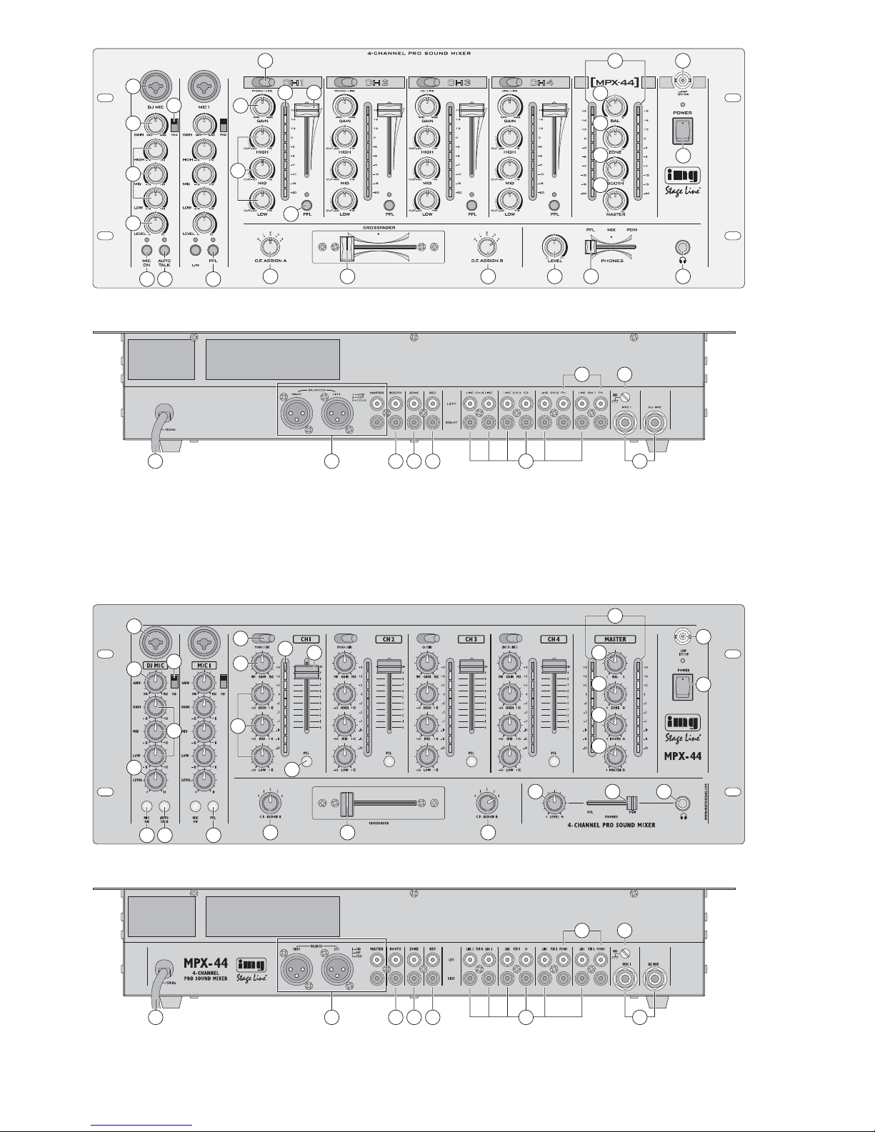
Bitte klappen Sie die Seite 3 heraus. Sie sehen
dann immer die beschriebenen Bedien elemente
und Anschlüsse.
1 Übersicht der Bedienelemente und
Anschlüsse
1.1 Frontseite
1 Eingangsbuchse (sym.), jeweils für den Mikrofon -
kanal DJ MIC und den Mikrofonkanal MIC 1; der
Mikrofonanschluss ist über XLR- oder 6,3-mmKlinkenste cker möglich
[Alternativ können auch die jeweiligen Mikrofon eingänge (35) auf der Rückseite ge nutzt werden.]
2 PAD-Schalter, jeweils für den Mikrofon kanal DJ
MIC und den Mikrofonkanal MIC 1:
bei nach unten geschobenem Schalter wird der
Eingangspegel des jeweiligen Mikrofons um
15 dB abgesenkt
3 Gain-Regler für die Eingangsverstärkung, je weils
für den Mikrofon kanal DJ MIC und den Mikrofonkanal MIC 1
4 3fache Klangregelung (max. ±12 dB), jeweils für
den Mikrofon kanal DJ MIC und den Mikrofonkanal MIC 1:
HIGH = Höhen, MID = Mitten, LOW = Bässe
5 Pegelregler, jeweils für den Mikrofon kanal DJ
MIC und den Mikrofonkanal MIC 1
6 Ein-/Ausschalttaste, jeweils für den Mikrofon -
kanal DJ MIC und den Mikrofonkanal MIC 1;
bei ge drückter Taste (MPX-44: LED über der
Taste leuch tet, MPX-44/ SW: Taste leuchtet) ist
das jeweilige Mikrofon eingeschaltet
7 Talkover-Taste für den DJ-Mikrofonkanal:
bei ge drückter Taste (MPX-44: LED über der
Taste leuch tet, MPX-44/SW: Taste leuchtet) werden bei Durchsagen über das DJ-Mikrofon die
Kanä le 1 –4 automatisch um 16 dB abgesenkt
8 Eingangsumschalter, jeweils für die Stereo-
Kanäle 1 – 4
9 Gain-Regler für die Eingangsverstärkung, je -
weils für die Stereo-Kanäle 1 – 4
10 LED-Pegelanzeige, jeweils für die Stereo-Kan ä -
le 1 – 4: Anzeige des Pre-Fader-Signalpegels,
d. h. des Signalpegels
vor
dem jeweiligen Kanal-
fader (11)
11 Pegelregler (Fader), jeweils für die Stereo-Kanä -
le 1 – 4
12 3fache Klangregelung (max. +15 dB, -30 dB),
jeweils für die Stereo-Kanäle 1 – 4:
HIGH = Höhen, MID = Mitten, LOW = Bässe
13 PFL-Taste, jeweils für die Stereo-Kanäle 1 – 4
und den Mikrofonkanal MIC 1;
bei ge drückter Tas te (MPX-44: LED über der Tas te leuchtet, MPX-44/ SW: Taste leuchtet) lässt
sich das Kanalsignal vor dem dazugehörigen
Pegelregler (5 bzw. 11) über einen Kopfhörer an
der Buchse (26) abhören
14 Stereo-LED-Pegelanzeige für das Ausgangs -
signal der Buchsen MASTER (30)
15 Balanceregler für das Ausgangssignal der Buch-
sen MASTER (30), BOOTH (31) und ZONE (32)
16 Pegelregler für den Ausgang ZONE (32)
17 Pegelregler für den Ausgang BOOTH (31)
18 Pegelregler für die MASTER-Ausgänge (30)
19 BNC-Buchse zum Anschluss einer Schwanen-
halsleuchte (12 V/5W max.)
20 Ein-/Ausschalter des Mischpults, mit darüber lie-
gender Betriebsanzeige
21 Zuordnungsschalter für die Überblendfunktion:
Aus wahl des Kanals, der eingeblendet wird, wenn
der Crossfader (22) nach links gezogen wird
22 Crossfader zum Überblenden zwischen zwei der
Stereo-Kanäle 1 – 4; die Kanäle werden mit den
C. F. ASSIGN-Schaltern (21 und 23) ausgewählt
(Wird die Überblendfunktion nicht benötigt, beide
Schalter auf „0“ stellen.)
23 Zuordnungsschalter für die Überblendfunktion:
Aus wahl des Kanals, der eingeblendet wird, wenn
der Crossfader (22) nach rechts gezogen wird
24 Lautstärkeregler für den Kopfhörerausgang
(26)
25 Überblendregler PHONES zur Auswahl des Ab -
hörsignals für den Kopfhörerausgang (26):
Fader ganz links („PFL“)
Vorhören („Pre Fader Listening“) der Kanäle,
deren Taste PFL (13) gedrückt ist
Fader ganz rechts („PGM“)
Abhören des laufenden Musikprogramms vor
den Ausgangsreglern (16, 17, 18)
26 6,3-mm-Klinkenbuchse zum Anschluss eines
Stereo-Kopfhörers (Impedanz min. 8 Ω)
1.2 Rückseite
27 Stereo-Eingänge PH [MPX-44] bzw. PHONO
[MPX-44/SW] (Cinch) für die Ka näle 1 und 2
zum Anschluss von Platten spielern mit Mag netsystem
28 Klemmschraube GND für den gemeinsamen
Masseanschluss von Plattenspielern
29 Netzkabel zum Anschluss an eine Netzsteck-
dose 230 V~/50 Hz
30 Stereo-Ausgänge MASTER – wahlweise XLR
(sym.) oder Cinch – für den An schluss des Hauptverstärkers
31 Stereo-Ausgang BOOTH (Cinch) für den An -
schluss eines weiteren Verstärkers, z.B. für die
Monitoranlage
32 Stereo-Ausgang ZONE (Cinch) für den An -
schluss eines weiteren Verstärkers, z.B. für die
Nebenraum-Beschallung
33 Stereo-Aufnahmeausgang (Cinch) für den An -
schluss eines Tonaufnahmegerätes; der Aufnahmepegel ist un abhängig von der Stel lung der
Ausgangsregler (16, 17, 18)
34 Stereo-Eingänge LINE und CD (Cinch) für die
Ka näle 1 – 4 zum Anschluss von Geräten mit
Line-Pe gel-Ausgängen (z. B. MD-Recorder, CDSpie ler)
Please unfold page 3. Then you can always see the
operating elements and connections de scribed.
1 Operating Elements and Connections
1.1 Front panel
1 Input jack (bal.), each for microphone channel
DJ MIC and microphone channel MIC 1; con nection of a microphone is possible via XLR plug
or 6.3 mm plug
[As an alternative, the corresponding microphone inputs (35) on the rear panel of the unit
may be used.]
2 PAD switch, each for microphone channel DJ
MIC and microphone channel MIC 1
with the switch in the lower position, the input
level of the corresponding microphone is atte nu ated by 15 dB
3 Gain control for the input amplification, each for
microphone channel DJ MIC and microphone
channel MIC 1
4 3-way tone control (±12 dB max.), each for
microphone channel DJ MIC and microphone
channel MIC 1:
HIGH, MID, LOW
5 Level control, each for microphone channel DJ
MIC and microphone channel MIC 1
6 On-off switch, each for microphone channel DJ
MIC and microphone channel MIC 1;
with the button pressed (MPX-44: LED above the
button lights up, MPX-44/ SW: button lights up),
the corresponding microphone is switched on
7 Talkover switch for the DJ microphone channel:
with the button pressed (MPX-44: LED above the
button lights up, MPX-44/ SW: button lights up),
the chan nels 1 to 4 are automatically attenuated
by 16 dB when announcements are made via the
DJ microphone
8 Input selector switch, each for the stereo chan-
nels 1 to 4
9 Gain control for the input amplification, each for
the stereo channels 1 to 4
10 LED level indication, each for the stereo chan-
nels 1 to 4: display of the prefader signal level,
i. e. of the signal level
ahead
of the correspond -
ing channel fader (11)
11 Level control (fader), each for the stereo chan-
nels 1 to 4
12 3-way equalizer (+15 dB,
-
30 dB max.), each for
the stereo channels 1 to 4:
HIGH, MID, LOW
13 PFL button, each for the stereo channels 1 to 4
and the microphone channel MIC 1:
with the button pressed (MPX-44: LED above the
button lights up, MPX-44/ SW: button lights up),
the channel signal can be monitored ahead of
the corresponding level control (5 or 11) via
headphones connected to the jack (26)
14 Stereo LED level indication for the output signal
of the jacks MASTER (30)
15 Balance control for the output signal at the jacks
MASTER (30), BOOTH (31), and ZONE (32)
16 Level control for the output ZONE (32)
17 Level control for the output BOOTH (31)
18 Level control for the MASTER outputs (30)
19 BNC jack for connecting a gooseneck light
(12 V/5W max.)
20 Power switch of the mixer with power LED above
it
21 Assignment switch for crossfading: selection of
the channel to be faded in with the crossfader
(22) moved to the left
22 Crossfader for crossfading between two of the
stereo channels 1 to 4; the channels are select ed with the C. F. ASSIGN switches (21 and 23).
[If cross fading is not required, set both switches
to “0”.]
23 Assignment switch for crossfading: selection of
the channel to be faded in with the crossfader
(22) moved to the right
24 Volume control for the headphone output (26)
25 Crossfading control PHONES for selecting the
monitoring signal for the headphone output
(26)
fader at the left stop (“PFL”)
prefader listening to the channels of which the
button PFL (13) has been pressed
fader at the right stop (“PGM”)
monitoring of the current music programme
ahead of the output controls (16, 17, 18)
26 6.3 mm jack for connecting stereo headphones
(minimum impedance 8 Ω)
1.2 Rear panel
27 Stereo inputs PH [MPX-44] or PHONO [MPX-
44/SW] (phono jacks) for the channels 1 and 2
for connecting turntables with magnetic system
28 Clamping screw GND for the common ground
connection of turntables
29 Mains cable for connecting the unit to a mains
socket 230 V~/50 Hz
30 Stereo outputs MASTER [optionally XLR jacks
(bal.) or phono jacks] for connecting the main
amplifier
31 Stereo output BOOTH (phono jacks) for connect -
ing another amplifier, e.g. for the monitoring
system
32 Stereo output ZONE (phono jacks) for connect -
ing another amplifier, e.g. for PA application in
adjoining rooms
33 Stereo recording output (phono jacks) for con -
necting an audio recorder; the recording level is
independent of the position of the output controls
(16, 17, 18)
34 Stereo inputs LINE and CD (phono jacks) for the
channels 1 to 4 for connecting units with line
level outputs (e. g. MD recorder, CD player)
35 Input jacks (6.3 mm jacks, bal.) for the micro-
phone channels DJ MIC and MIC 1; as an alternative to the corresponding microphone inputs
(1) on the front panel
4
GB
D
A
CH
35 Eingangsbuchsen (6,3-mm-Klinke, sym.) für die
Mikrofonkanäle DJ MIC und MIC 1; alternativ zu
den jeweiligen Mi krofon ein gängen (1) auf der
Frontseite
2 Hinweise für den sicheren Gebrauch
Dieses Gerät entspricht allen erforderlichen Richt linien der EU und deshalb mit gekennzeichnet.
Beachten Sie auch unbedingt die folgenden Punkte:
Das Gerät ist nur zur Verwendung im Innenbereich geeignet. Schützen Sie es vor Tropf- und
Spritz wasser, hoher Luftfeuchtigkeit und Hit ze
(zulässiger Einsatztemperaturbereich 0 – 40 °C).
Stellen Sie keine mit Flüssigkeit gefüllten Gefäße,
z. B. Trinkgläser, auf das Gerät.
Nehmen Sie das Gerät nicht in Betrieb bzw. zie hen Sie sofort den Netzstecker aus der Steckdose:
1. wenn sichtbare Schäden am Gerät oder an der
Netz anschlussleitung vor handen sind,
2. wenn nach einem Sturz oder Ähnlichem der
Verdacht auf einen Defekt besteht,
3. wenn Funktionsstörungen auftreten.
Lassen Sie das Gerät in jedem Fall in einer Fachwerkstatt reparieren.
Eine beschädigte Netzanschlussleitung darf nur
durch eine Fachwerkstatt ersetzt werden.
Ziehen Sie den Netzstecker nie am Kabel aus der
Steckdose, fassen Sie immer am Stecker an.
Verwenden Sie zum Reinigen nur ein trockenes,
weiches Tuch, niemals Wasser oder Chemikalien.
Wird das Gerät zweckentfremdet, nicht richtig
angeschlossen, falsch be dient oder nicht fach -
gerecht re pa riert, kann keine Haftung für daraus
resultierende Sach- oder Personenschäden und
keine Garantie für das Gerät übernommen werden.
3 Einsatzmöglichkeiten
Das Mischpult ist für beliebige DJ-An wen dungen im
privaten oder professionellen Be reich geeignet. Es
lassen sich bis zu sechs Geräte mit Line-Pegel (z. B.
CD-Spieler), bis zu zwei Plattenspieler und zwei
Mikrofone an schlie ßen.
Das Mischpult ist für die Montage in ein Rack für
Geräte mit einer Breite von 482 mm (19") vorgesehen. Für den Einbau werden 4 HE (Höheneinheiten)
= 177 mm benötigt. Es kann jedoch auch frei aufgestellt werden.
4 Geräte anschließen
Vor dem Anschließen von Geräten bzw. Ändern be stehender Anschlüsse das Mischpult ausschalten.
1) Die Stereo-Tonquellen an die entsprechenden
Cinch-Eingangsbuchsen der Kanäle 1 – 4 an -
schlie ßen (weiße Buchse LEFT = linker Kanal;
rote Buchse RIGHT = rechter Kanal):
– Geräte mit Line-Pegel-Ausgang (z. B. MD-Re -
corder, CD-Spie ler, Kassettenrecorder) an die
Buchsen LINE oder CD (34);
– Plattenspieler mit Magnetsystem an die Buch-
sen PH [MPX-44] bzw. PHONO [MPX-44/SW]
(27). Die Klemmschraube GND (28) kann als
gemeinsamer Massepunkt ge nutzt werden:
Den Masseanschluss der Plattenspieler mit
der Klemmschraube verbinden.
2) Es lassen sich zwei Mikrofone anschließen: ein
DJ-Mikrofon an den DJ-Mikrofonkanal DJ MIC
und ein weiteres Mikrofon an den zweiten Mikrofonkanal MIC 1. Das jeweilige Mikrofon entweder
über einen XLR- oder einen 6,3-mm-Klinkenste cker an den Mikrofoneingang (1) auf der Frontplatte anschließen oder über einen 6,3-mm-Klinkenstecker an den entsprechenden Mikrofon ein gang (35) auf der Rückseite.
3) Zum Anschluss von Verstärkern stehen mehrere
Stereo-Ausgänge mit eigenen Pegelreglern zur
Verfügung:
– die Ausgänge MASTER (30); hier sollte der
Hauptverstärker für die Saalbeschallung an ge schlos sen werden, wahlweise an den sym me trischen XLR- oder an den Cinch-Ausgang
– der Ausgang BOOTH (31); hier kann z.B. der
Verstärker für eine Monitoranlage an ge schlos sen werden
– der Ausgang ZONE (32); hier kann z.B. ein
zusätzlicher Verstärker für eine NebenraumBeschallung angeschlossen werden
4) Sollen Tonaufnahmen gemacht werden, das Aufnahmegerät an den Stereo-Ausgang REC (33)
an schlie ßen. Der Aufnahmepegel ist unabhängig
von der Stellung der drei Ausgangsregler ZONE,
BOOTH und MASTER (16, 17, 18).
5) An die 6,3-mm-Klinkenbuchse (26) kann ein
Stereo-Kopfhörer (Impedanz min. 8 Ω) angeschlossen werden, zum Vorhören der Eingangskanäle oder zum Abhören des laufenden Musikprogramms vor den drei Ausgangsreglern ZONE,
BOOTH und MASTER (16, 17, 18).
6) Zur Pultbeleuchtung kann eine Schwanenhalsleuchte (12 V/5 W max.) an die BNC-Buchse
LAMP (19) an ge schlossen werden, z. B. die
Leuch te GNL-205 aus dem Programm von „img
Stage Line“. Die Leuchte wird mit dem Mischpult
ein- und ausgeschaltet.
7) Zuletzt den Stecker des Netzkabels (29) in eine
Steckdose (230 V~/50 Hz) stecken.
Soll das Gerät endgültig aus dem Be trieb
ge nom men werden, übergeben Sie es zur
umweltgerechten Entsorgung ei nem örtlichen Re cyc ling be trieb.
WARNUNG Das Gerät wird mit lebensgefährli-
cher Netzspannung (230 V~) versorgt. Nehmen Sie deshalb nie selbst
Eingriffe am Gerät vor. Durch un sachge mäßes Vorgehen besteht die
Gefahr eines elektrischen Schlages.
2 Safety Notes
This unit corresponds to all required directives of the
EU and is therefore marked with .
Please observe the following items in any case:
The unit is suitable for indoor use only. Protect it
against dripping water and splash water, high air
humidity, and heat (admissible ambient temperature range 0 – 40°C).
Do not place any vessel filled with liquid on the
unit, e. g. a drinking glass.
Do not operate the unit or immediately disconnect
the plug from the mains socket
1. if there is visible damage to the unit or to the
mains cable,
2. if a defect might have occurred after the unit
was dropped or suffered a similar accident,
3. if malfunctions occur.
In any case the unit must be repaired by skilled
personnel.
A damaged mains cable must be replaced by
skilled personnel only.
Never pull the mains cable for disconnecting the
mains plug from the socket, always seize the plug.
For cleaning only use a dry, soft cloth; never use
chemicals or water.
No guarantee claims for the unit and no liability for
any resulting personal damage or material
damage will be accepted if the unit is used for
other purposes than originally intended, if it is not
correctly connected, operated or not repaired in
an expert way.
Important for U. K. Customers!
The wires in this mains lead are coloured in ac cord ance with the following code:
blue = neutral
brown = live
As the colours of the wires in the mains lead of this
appliance may not correspond with the coloured
markings identifying the terminals in your plug,
proceed as follows:
1. The wire which is coloured blue must be con nected to the terminal in the plug which is
marked with the letter N or coloured black.
2. The wire which is coloured brown must be con nected to the terminal which is marked with the
letter L or coloured red.
3 Applications
The mixer is suitable for any private or professional
DJ applications. It allows connection of up to six
units with line level (e. g. CD player), up to two turntables, and two mi cro phones.
The mixer is designed for installation into a rack
for units of a width of 482 mm (19"). For rack installation, 4 RS (rack spaces) = 177 mm are required.
However, the mixer can also be placed as desired.
4 Connection
Switch off the mixer prior to connecting any units or
to changing any existing connections.
1) Connect the stereo audio sources to the corre-
sponding phono input jacks of the channels 1 to 4
(white jack LEFT; red jack RIGHT):
– units with line level output (e. g. MD recorder,
CD player, cassette recorder) to the jacks
LINE or CD (34);
– turntables with magnetic system to the jacks
PH [MPX-44] or PHONO [MPX-44/SW] (27).
The clamping screw GND (28) can be used as
a common ground: Connect the ground con nection of the turntables to the clamping screw.
2) Connection of two microphones is possible:
Connect a DJ microphone to the DJ microphone
channel DJ MIC and another microphone to the
second microphone channel MIC 1. Either con nect the corresponding microphone via an XLR
plug or a 6.3 mm plug to the microphone input (1)
on the front panel or via a 6.3 mm plug to the corresponding microphone input (35) on the rear
panel.
3) For connecting amplifiers, several stereo outputs
with individual level controls are available:
– outputs MASTER (30): it is recommended to
connect the main amplifier for PA application in
halls to these outputs, optionally to the bal anced XLR output or to the phono output
– output BOOTH (31): it is possible to connect
e. g. the amplifier for a monitoring system to
this output
– output ZONE (32): it is possible to connect
e. g. an additional amplifier for PA application
in adjoining rooms to this output
4) For audio recordings, connect the recorder to the
stereo output REC (33). The recording level is in dependent of the position of the three output controls ZONE, BOOTH, and MASTER (16, 17, 18).
5) For prefader listening to the input channels or for
monitoring the current music programme ahead
of the three output controls ZONE, BOOTH, and
MASTER (16, 17, 18), it is possible to connect
stereo headphones (minimum impedance 8 Ω) to
the 6.3 mm jack (26).
6) For illuminating the console, it is possible to con nect a gooseneck light (12 V/5W max.) to the
BNC jack LAMP (19), e. g. the light GNL-205
from the “img Stage Line” range. The light is
switched on or off with the mixer.
7) Finally connect the plug of the mains cable (29)
to a mains socket (230 V~/50 Hz).
If the unit is to be put out of operation de fin itively, take it to a local recycling plant for a
disposal which is not harmful to the environment.
WARNING The unit is supplied with hazardous
mains voltage (230 V~). Leave ser vicing to skilled personnel only. In expert handling may cause an electric shock hazard.
5
GB
D
A
CH
5 Bedienung
Vor dem Einschalten die Ausgangsregler ZONE,
BOOTH und MASTER (16, 17, 18) auf Minimum
stellen, um Einschaltgeräusche zu vermeiden. Das
Mischpult mit dem Schalter POWER (20) einschalten. Die Betriebsanzeige über dem Schalter leuchtet.
Nach dem Betrieb das Mischpult wieder mit dem
Schalter POWER ausschalten.
5.1 Grundeinstellungen
5.1.1 Stereo-Eingangskanäle 1 –4
Vorab alle Gain-Reg ler (9) und Klangregler (12) so wie den Ba lan ceregler (15) in die Mittelposition drehen. Die zwei Zuordnungsschalter für die Überblendfunktion C.F. ASSIGN A und B (21, 23) auf „0“
stellen.
Zum Aussteuern eines Kanals:
1) Mit dem Eingangsumschalter (8) des Kanals die
Buchsen der gewünschten Signalquelle an wäh len.
2) Ein Tonsignal (z. B. Musikstück) auf den Eingang
geben.
3) Den Fader (11) des Kanals bis ca.
2
/3 des Maxi-
mums aufziehen.
4) Um das Signal über die Lautsprecher einer angeschlossenen PA-Anlage abzuhören, den jeweiligen Ausgangsregler – ZONE (16), BOOTH (17)
oder MASTER (18) – aufdrehen. (Das Signal
lässt sich auch über einen Kopfhörer ab hören
– siehe dazu Kap. 5.4.)
5) Die Kanal-Pegelanzeige (10) zeigt den Signal pegel
vor
dem Kanalfader (Pre-Fader-Pegel) an.
An hand der Pegelanzeige mit dem Gain-Regler
(9) des Kanals den Eingang aus steuern: Optimale Aussteuerung liegt vor, wenn bei durch schnittlich lauten Passagen Werte im 0-dB- Be reich an ge zeigt werden. Leuchtet die rote +9-dBLED auf, ist der Kanal über steuert. Falls erforderlich, kann der Gain-Reg l er auch ganz auf MIN
bzw. MAX ge dreht werden.
6) Mit den drei Klangreglern (12) des Kanals das
ge wünschte Klangbild einstellen. Durch Verstellen der Regler lassen sich die Höhen (HIGH),
Mitten (MID) und Bässe (LOW) an he ben (bis
max. 15 dB) bzw. stark absenken (bis max.
30 dB). Stehen die Regler in Mittelstellung, findet
keine Frequenzgangbeeinflussung statt.
Even tuell muss nach der Klangeinstellung der
Kanalpegel noch einmal mit dem Gain-Regler
korrigiert werden.
5.1.2 Mikrofonkanäle
Zum Aussteuern eines Mikrofonkanals vorab den
Gain-Regler (3) und die Klangregler (4) des Kanals
in die Mittelposition und den Schalter PAD (2) des
Kanals in die obere Position stellen.
1) Zum Einschalten des Mikrofons die Taste MIC
ON (6) des Kanals drücken (MPX-44: LED über
der Taste leuchtet, MPX-44/SW: Tas te leuchtet).
2) Den Pegelregler LEVEL (5) des Kanals und den
Masterregler (18) bis ca.
2
/3 des Maximums auf-
drehen.
3) In das Mikrofon sprechen. Den Gain-Regler (3)
des Kanals so ein stellen, dass die Stereo-Pegel anzeige (14) Werte im 0-dB-Bereich anzeigt (der
Regler kann ggf. auch ganz zu- oder aufgedreht
werden).
Tritt eine akustische Rückkopplung auf (lauter
Pfeifton) oder ist der Eingangspegel auch bei
zugedrehtem Gain-Regler noch zu hoch, den
PAD-Schalter (2) des Kanals in die untere Position schie ben: Der Eingangspegel wird dann um
15 dB abgesenkt.
4) Den Klang mit der 3fachen Klangregelung (4)
des Kanals einstellen: die Hö hen (HIGH), Mitten
(MID) und Bäs se (LOW) lassen sich bis max.
12 dB an heben oder absenken. Eventuell da nach
den Kanalpegel mit dem Gain-Regler korrigieren.
5) Zur besseren Verständlichkeit einer Durchsage
bei laufendem Musikprogramm kann für das DJMikrofon mit der Taste AUTO TALK (7) die Talk over-Funktion eingeschaltet werden: Ist die Taste
ge drückt (MPX-44: LED über der Taste leuchtet,
MPX-44/SW: Tas te leuchtet), werden bei Durchsagen über das DJ-Mikrofon die Pegel der Stereo-Kanäle 1 – 4 au tomatisch um 16 dB ab gesenkt. Zum Ab schal ten der Funktion die Taste
wieder ausrasten.
5.1.3 Ausgangskanäle
Das Ausgangssignal wird auf die regelbaren Ausgänge MAS TER (30), BOOTH (31) und ZONE (32)
sowie auf den Aufnahmeausgang REC (33) – ohne
eigenen Pegelregler – gegeben.
1) Die Stereo-Pegelanzeige (14) zeigt den Pegel
des Signals an den Ausgängen MASTER an.
Den Pegel an hand der Pegelanzeige mit dem
Regler MASTER (18) op timal aussteuern. In der
Regel wird eine optimale Aussteuerung er reicht,
wenn die Pegelanzeige Wer te im 0-dB-Be reich
an zeigt. Ist der Aus gangs pegel jedoch für das
nachfolgende Gerät zu hoch oder zu niedrig,
muss das Signal entsprechend niedriger oder
höher ausgesteuert werden.
2) Mit dem Regler BOOTH (17) den gewünschten
Signalpegel für den Ausgang BOOTH einstellen.
3) Mit dem Regler ZONE (16) den gewünschten
Signalpegel für den Ausgang ZONE einstellen.
4) Mit dem Balanceregler BAL (15) die Balance für
die Ausgänge MASTER, BOOTH und ZONE einstellen.
VORSICHT Stellen Sie die Lautstärke der Audio -
an lage und die Kopfhörerlautstärke
nie sehr hoch ein. Hohe Laut stärken
können auf Dauer das Gehör schädigen! Das mensch liche Ohr gewöhnt
sich an große Lautstärken und empfindet sie nach ei niger Zeit als nicht
mehr so hoch. Darum eine hohe Laut stärke nach der Gewöhnung nicht
wei ter erhöhen.
5 Operation
Prior to switching on, set the output controls ZONE,
BOOTH, and MASTER (16, 17, 18) to minimum to
prevent switching noise. Switch on the mixer with
the switch POWER (20). The power LED above the
switch lights up.
After operation, switch off the mixer with the switch
POWER.
5.1 Basic adjustments
5.1.1 Stereo input channels 1 to 4
First set all gain controls (9), equalizer controls (12),
and the balance control (15) to mid-position. Then
set the two switches for crossfading C.F. ASSIGN A
and B (21, 23) to “0”.
Level control of a channel:
1) Use the input selector switch (8) of the channel to
select the jacks of the desired signal source.
2) Feed an audio signal (e. g. music piece) to the
input.
3) Advance the fader (11) of the channel to approx.
2
/3 of its maximum.
4) To monitor the signal via the speakers of a PA
system connected, advance the corresponding
output control – ZONE (16), BOOTH (17), or
MASTER (18). [The signal can also be monitored
via headphones – see chapter 5.4.]
5) The level indication (10) of the channel displays
the signal level
ahead of
the channel fader (pre-
fader level). Via the level indication, control the
level of the input with the gain control (9) of the
channel: In case of optimum level control, values
in the 0 dB range are displayed at average vol ume. If the red +9 dB LED lights up, there is an
overload of the channel. If required, turn the gain
control fully to MIN or MAX.
6) Adjust the desired sound with the three equalizer
controls (12) of the channel. By adjusting the
controls, the high frequencies (HIGH), midrange
frequencies (MID), and low frequencies (LOW)
can be boosted (up to 15 dB max.) or substan tially attenuated (up to 30 dB max.). With the controls in mid-position, the frequency response is
not affected.
After the sound adjustment, readjust the
channel level once again with the gain control, if
requir ed.
5.1.2 Microphone channels
For level control of a microphone channel, first set
the gain control (3) and the tone controls (4) of the
channel to mid-position and set the switch PAD (2)
of the channel to the upper position.
1) To switch on the microphone, press the button
MIC ON (6) of the channel (MPX-44: LED above
the button lights up, MPX-44/ SW: button lights
up).
2) Advance the control LEVEL (5) of the channel
and the master control (18) to approx.
2
/3 of its
maximum.
3) Speak into the microphone. Adjust the gain control (3) of the channel in such a way that the
stereo level indication (14) displays values in the
0 dB range (if required, the control can be fully
opened or closed).
In case of howlback (loud whistling) or if the
input level is too high even with the gain control
closed, set the PAD switch (2) of the channel to
the lower position: The input level will be attenu ated by 15 dB.
4) Adjust the sound with the 3-way tone control (4)
of the channel: the high frequencies (HIGH) mid -
range frequencies (MID) and low frequencies
(LOW) can be attenuated or boost ed up to 12 dB
max. Readjust the channel level with the gain
control afterwards, if required.
5) To improve the audibility of an announcement
during the current music programme, the talkover
function can be switched on for the DJ microphone with the button AUTO TALK (7): With the
button pressed (MPX-44: LED above the button
lights up, MPX-44/ SW: button lights up), the
levels of the stereo channels 1 to 4 are automatically attenu ated by 16 dB when announcements
are made via the DJ microphone. To switch off
the function, unlock the button.
5.1.3 Output channels
The output signal is fed to the adjustable outputs
MASTER (30), BOOTH (31), ZONE (32) and to the
recording output REC (33) without individual level
control.
1) The stereo level indication (14) displays the level
of the signal at the outputs MASTER. Via the
level indication, adjust an optimum level with the
control MASTER (18). Usually, an optimum level
is obtained if the level indication displays values
in the 0 dB range. However, if the output level is
too high or too low for the following unit, the signal must be controlled to a correspondingly lower
or higher level.
2) With the control BOOTH (17), adjust the desired
signal level for the output BOOTH.
3) With the control ZONE (16), adjust the desired
signal level for the output ZONE.
4) With the balance control BAL (15), adjust the
balance for the outputs MASTER, BOOTH, and
ZONE.
5) The recording signal at the output REC can be
monitored via headphones – see chapter 5.4. It is
not affected by the controls MASTER, BOOTH,
and ZONE (the signal is taken off
ahead of
the
output controls).
CAUTION Never adjust the audio system or the
headphones to a very high volume.
Permanent high volumes may dam age your hearing! The human ear will
get accustomed to high volumes
which do not seem to be that high
after some time. Therefore, do not
further increase a high volume after
getting used to it.
6
GB
D
A
CH
 Loading...