

IMG STAGELINE MPX-30DMP Instruction Manual
ELECTRONICS FOR SPECIALISTS ELECTRONICS FOR SPECIALISTS ELECTRONICS FOR SPECIALISTS ELECTRONICS FOR SPECIALISTS
BEDIENUNGSANLEITUNG
INSTRUCTION MANUAL
MODE D’EMPLOI
ISTRUZIONI PER L’USO
GEBRUIKSAANWIJZING
MANUAL DE INSTRUCCIONES
INSTRUKCJA OBSŁUGI
SIKKERHEDSOPLYSNINGER
SÄKERHETSFÖRESKRIFTER
TURVALLISUUDESTA
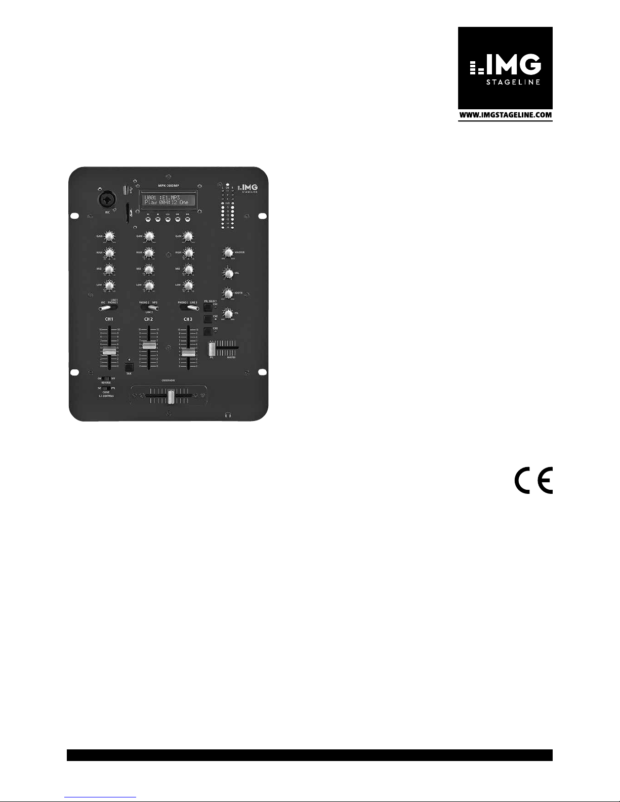
Stereo-DJ-Mischpult
mit MP3-Spieler
Stereo DJ Mixer
with MP3 Player
MPX-30DMP
Bestell-Nr. • Order No. 20.2760

2
Deutsch ...........Seite 4
English ............Page 7
Français ...........Page 10
Italiano............Pagina 13
Nederlands ........Pagina 16
Español ...........Página 19
Polski .............Strona 22
Dansk .............Sida 25
Svenska ...........Sidan 25
Suomi.............Sivulta 25
ELECTRONICS FOR SPECIALISTS ELECTRONICS FOR SPECIALISTS ELECTRONICS FOR SPECIALISTS ELECTRONICS FOR SPECIALISTS
3
12
3
11
12
13
14
15
16
17
18
19
10
9
8
7
6
5
4
3
2
1
A
B
C
D
MID
+12
CUT
-
32 dB
+12
CUT
-
32 dB
GAIN
MAXMIN
LOW
+12
CUT
-
32 dB
HIGH
MID
+12
CUT
-
32 dB
+12
CUT
-
32 dB
GAIN
MAXMIN
LOW
+12
CUT
-
32 dB
HIGH
MID
+12
CUT
-
32 dB
+12
CUT
-
32 dB
GAIN
MAXMIN
MAXMIN
MAXMIN
MAXMIN
LOW
+12
CUT
-
32 dB
HIGH
MIC
LINE1
PHONO1 PHONO 2 MP3 PHONO 3 LINE 3
C.F. CONTROLS
REVERSE
CURVE
ON OFF
TALK
0
1
2
3
4
5
6
7
8
9
10
0
1
2
3
4
5
6
7
8
9
10
0
1
2
3
4
5
6
7
8
9
10
0
1
2
3
4
5
6
7
8
9
10
0
1
2
3
4
5
6
7
8
9
10
0
1
2
3
4
5
6
7
8
9
10
LINE 2
PFL MASTER
CROSSFADER
PFL SELECT
CH1
CH2
CH3
MASTER
BAL
RL
BOOTH
PFL
MIC
ON
11
8
5
0dB
-5
-9
-12
-15
-20
-25
L R
CH 1
CH 2
CH 3
C
MPX-30DMP
MPX-30DMP
21
3
21
3
23 24 25 26 27
20
21
22
28
POWER
GND GND
LINE1
PHONO1
INPUT1INPUT2
LINE2 PHONO2
INPUT3
LINE3 PHONO3RECBOOTHMASTER
OUTPUT
R
BAL.
L
BAL.
LINE1 /
PHONO1
R
L
230V~
50Hz
FUSE
MPX-30DMP
➀
➁

4
Deutsch
Stereo-DJ-Mischpult
Diese Anleitung richtet sich an Benutzer
mit Grundkenntnissen in der Audiotechnik.
Bitte lesen Sie die Anleitung vor dem Betrieb
gründlich durch und heben Sie sie für ein späteres Nachlesen auf.
Auf der ausklappbaren Seite 3 finden
Sie alle beschriebenen Bedienelemente und
Anschlüsse.
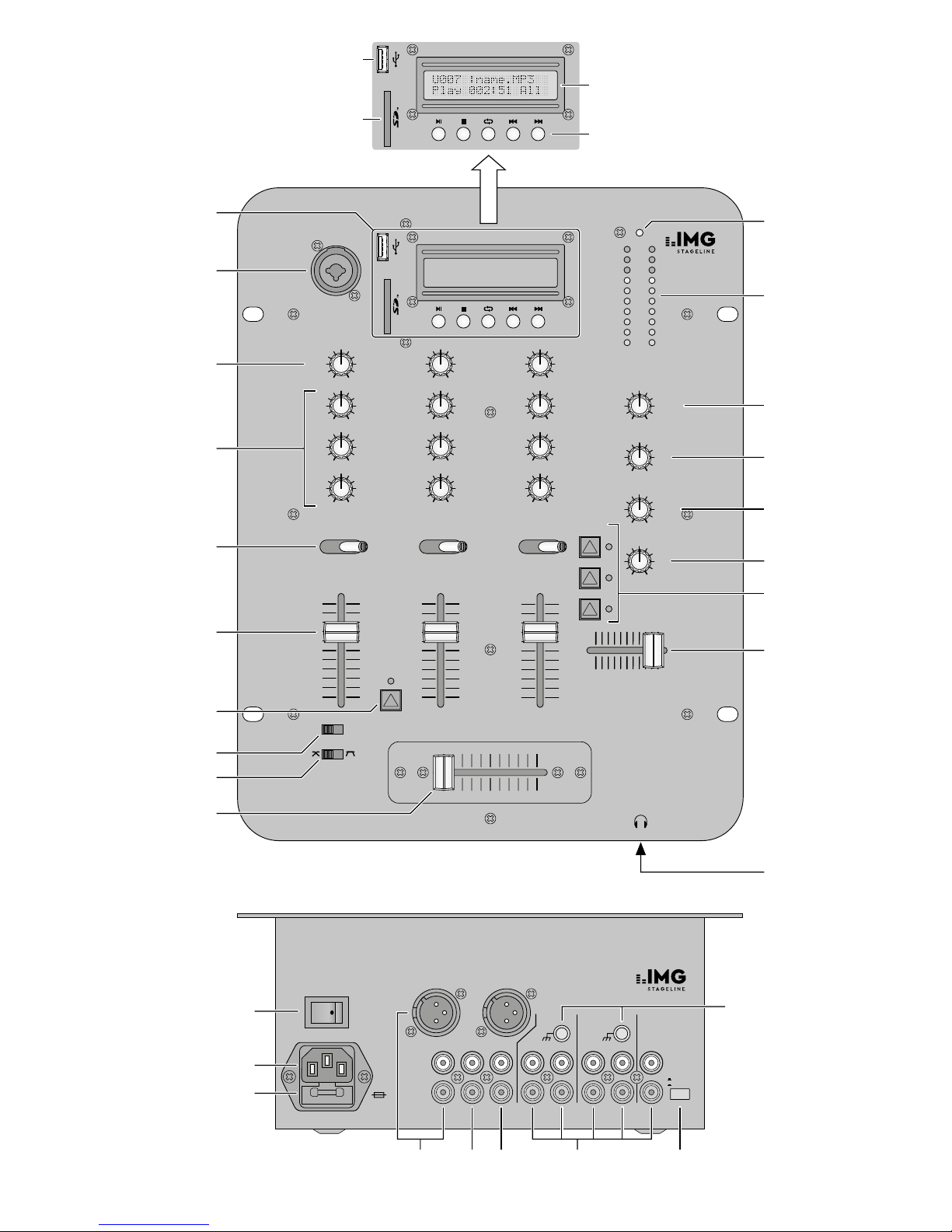
1 Übersicht der Anschlüsse
und Bedienelemente
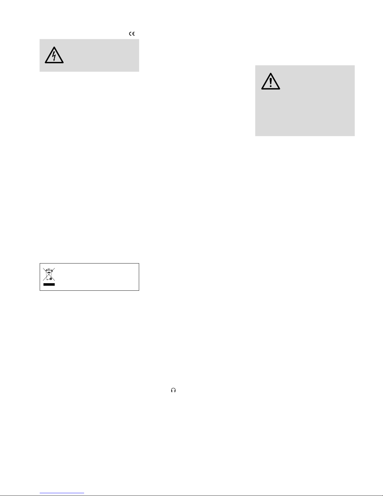
1.1 Ober- und Vorderseite
1 MP3-Spieler
A
USB-Buchse zum Einstecken eines
USB-Sticks oder zum Anschluss einer
Festplatte mit eigener Stromversorgung
B Steckplatz für eine SD / SDHC-Karte
C Display, zeigt
in der oberen Zeile
– das angewählte Abspielmedium („U“
für USB-Speicher, „S“ für SD / SDHCKarte) und die Nummer des Titels
bzw. im Modus „Stop“ die Anzahl
der Titel
– den Dateinamen des Titels
in der unteren Zeile
– den Betriebsmodus („Play“, „Pause“
„Stop“)
– abwechselnd die bereits gespielte Zeit
des Titels und seine Gesamtlaufzeit
bzw. im Modus „Stop“ die Zeitanzeige „000:00“
– „All“ bei ständiger Wiederholung
aller Titel oder „One“ bei ständiger
Wiederholung eines Titels
D Bedientasten
– Taste
II
, um das Abspielen zu starten
und zu unterbrechen
– Taste , um das Abspielen zu beenden
– Taste , zum Umschalten zwischen
ständiger Wiederholung eines Titels
(Anzeige „One“) oder aller Titel (An-
zeige „All“)
– Tasten
I
und
I
, um einen Titel
vor oder zurück zu springen; für den
schnellen Vor- oder Rücklauf im Titel
die jeweilige Taste gedrückt halten
2
Mikrofoneingang (kombinierte Buchse
XLR / 6,3-mm-Klinke, sym.) für Kanal CH 1
3
Regler GAIN für die Eingangsverstärkung,
für jeden Eingangskanal
4 Klangregler, für jeden Eingangskanal
HIGH : Höhen, MID : Mitten, LOW : Tiefen
5
Eingangswahlschalter,
für jeden Eingangskanal
CH 1 links Eingang MIC
rechts Eingang LINE 1/ PHONO 1
CH 2 links Eingang PHONO 2
Mitte Eingang LINE 2
rechts MP3-Spieler
CH 3 links Eingang PHONO 3
rechts Eingang LINE 3
6 Fader zum Einstellen des Kanalpegels,
für jeden Eingangskanal
7
Taste TALK (mit Kontroll-LED) zum
Stummschalten der Kanäle CH 2 und CH 3
bei Mikrofondurchsagen
8
Schalter REVERSE zum Auswählen auf
welche Seite des Crossfaders (10) die
Kanäle CH 2 und CH 3 geschaltet werden
ON links Kanal CH 3, rechts Kanal CH 2
OFF links Kanal CH 2, rechts Kanal CH 3
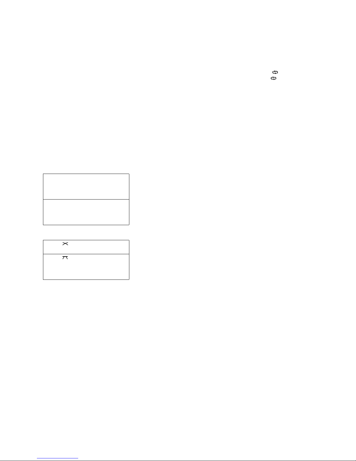
9
Schalter CURVE für das Überblendverhalten des Crossfaders (10)
weiches, gleichmäßiges Überblen-
den
hartes Überblenden mit einem wei-
ten Bereich, in dem beide Kanäle
gleich laut zu hören sind
10 Überblendregler (Crossfader) für die Ka-
näle CH 2 und CH 3
Wird die Überblendfunktion nicht benötigt, den Crossfader in die Mitte schieben.
11 Betriebsanzeige
12
Stereo-Pegelanzeige für das mit dem
Regler MASTER (13) eingestellte Summensignal
13
Gesamt-Pegelregler MASTER: bestimmt
den Pegel des Summensignals, das über
die Ausgänge R BAL. / L BAL. und MASTER
(23) ausgegeben wird
14
Balance-Regler für das mit dem Regler
MASTER (13) eingestellte Summensignal
15
Gesamt-Pegelregler BOOTH: bestimmt
den Pegel des Summensignals, das über
den BOOTH-Ausgang (24) ausgegeben
wird
16
Lautstärkeregler für den Kopfhörerausgang (19)
17
Vorhörtaste für jeden Eingangskanal
(mit Kontroll-LED): bei gedrückter Taste
lässt sich das zugehörige Kanalsignal vor
dem Fader (6) über einen Kopfhörer an
der Buchse (19) abhören (PFL = „Pre
Fader Listening“).
18 Regler zur Auswahl des Abhörsignals für
den Kopfhörerausgang (19)
Position PFL
Vorhören der Kanäle, deren Taste PFL
SELECT (17) gedrückt ist
Position MASTER
Abhören der Signalsumme vor den
Ausgangsreglern (13, 15)
19
6,3-mm-Klinkenbuchse zum Anschluss
eines Stereo-Kopfhörers (Impedanz
min.8 Ω)
1.2 Rückseite
20 Ein- /Ausschalter POWER
21
Netzbuchse zum Anschluss an eine Steckdose (230 V/ 50 Hz) über das beiliegende
Netzkabel
22
Halterung für die Netzsicherung; eine
geschmolzene Sicherung nur durch eine
gleichen Typs ersetzen
23
Stereo-Ausgänge R BAL. / L BAL. (XLR-Ein
baustecker, sym.) und MASTER (Cinch Buchsen) zum Anschluss des Verstärkers
für die Beschallung
Der XLR-Ausgang und der Cinch-Ausgang
können auch gleichzeitig zum Anschluss
von zwei Verstärkern verwendet werden.
Der Ausgangspegel wird mit dem Regler
MASTER (13) eingestellt.
24
Stereo-Ausgang BOOTH (Cinch-Buchsen)
für den Anschluss eines weiteren Verstärkers, z. B. für eine Monitoranlage oder
eine Nebenraum-Beschallung; der Ausgangspegel wird mit dem Regler BOOTH
(15) eingestellt
25
Stereo-Ausgang REC (Cinch-Buchsen) für
den Anschluss eines Aufnahmegerätes;
der Aufnahmepegel ist unabhängig von
der Stellung der Ausgangsregler (13, 15)
26
Stereo-Eingänge (Cinch-Buchsen) zum
Anschluss von Tonquellen an die Kanäle
CH 1 bis CH 3
INPUT 2, INPUT 3:
Eingänge PHONO für Plattenspieler mit
Magnetsystem,
Eingänge LINE für Geräte mit Line-Pegel-Ausgang, z. B. CD-Spieler, Tapedeck,
Radio
INPUT 1:
Der Eingang kann mit der daneben liegenden Taste zwischen PHONO und LINE umgeschaltet werden: ☞ siehe Position 27.
27 LINE / PHONO-Umschalter, um den dane-
ben liegenden Eingang für Kanal CH 1
auf Line-Signalpegel (Taste ausgerastet)
oder Phono-Signalpegel (Taste gedrückt)
zu schalten
28 Masse-Klemmschrauben GND für ange-
schlossene Plattenspieler
5
Deutsch
2 Hinweise für den
sicherenGebrauch
Das Gerät entspricht allen relevanten Richtlinien der EU und trägt deshalb das -Zeichen.
WARNUNG
Das Gerät wird mit lebensgefährlicher Netzspannung
versorgt. Nehmen Sie deshalb
niemals selbst Eingriffe daran
vor. Durch unsachbemäßes
Vorgehen besteht die Gefahr
eines elektrischen Schlages.
•
Das Gerät ist nur zur Verwendung im Innenbereich geeignet. Schützen Sie es vor
Tropf- und Spritzwasser, hoher Luftfeuchtigkeit und Hitze (zulässiger Einsatztemperaturbereich 0 – 40 °C).
•
Stellen Sie keine mit Flüssigkeit gefüllten
Gefäße, z. B. Trinkgläser, auf das Gerät.
•
Ziehen Sie sofort den Netzstecker aus der
Steckdose:
1. wenn sichtbare Schäden am Gerät oder
am Netzkabel vorhanden sind,
2.
wenn nach einem Sturz oder Ähnlichem
der Verdacht auf einen Defekt besteht,
3. wenn Funktionsstörungen auftreten.
Lassen Sie das Gerät in jedem Fall in einer
Fachwerkstatt reparieren.
•
Ziehen Sie den Netzstecker nie am Kabel
aus der Steckdose, fassen Sie immer am
Stecker an.
•
Verwenden Sie zum Reinigen nur ein trockenes, weiches Tuch, niemals Wasser oder
Chemikalien.
•
Wird das Gerät zweckentfremdet, nicht
richtig angeschlossen, falsch bedient oder
nicht fachgerecht repariert, kann keine
Haftung für daraus resultierende Sach-
oder Personenschäden und keine Garantie
für das Gerät übernommen werden.
Soll das Gerät endgültig aus dem
Betrieb genommen werden, überge
-
ben Sie es zur umweltgerechten Ent
sorgung einem örtlichen Recyclingbetrieb.
3 Einsatzmöglichkeiten
Das 3-Kanal-Mischpult MPX-30DMP ist für
beliebige DJ-Anwendungen im privaten oder
professionellen Bereich geeignet. Das Gerät
bietet Anschlussmöglichkeiten für Geräte mit
Line-Pegel (z. B. CD-Spieler), Plattenspieler
und ein DJ-Mikrofon. Als zusätzliche Tonquelle steht der integrierte MP3-Spieler zur
Verfügung, mit dem sich MP3-Audiodateien
von USB-Speichern (z. B. USB-Sticks) und
SD / SDHC-Karten (max. 32 GB) abspielen
lassen. Alle Tonquellen können über einen
Kopfhörer vorgehört werden („Pre Fader Listening“).
Das Mischpult kann sowohl frei aufgestellt
als auch in ein Bedienpult eingebaut werden.
4 Anschluss
Vor dem Anschluss bzw. vor dem Verändern
von Anschlüssen das Mischpult und die anzuschließenden Geräte ausschalten.
1)
Die Stereo-Tonquellen an die entsprechenden Cinch-Eingangsbuchsen (26) der
Kanäle CH 1 bis CH 3 anschließen (weiße
Buchse L = linker Kanal; rote Buchse R
=rechter Kanal):
Geräte mit Line-Pegel-Ausgang (z. B.
CD-Spieler, Tapedeck, Radio) lassen sich
anschließen an
– den Eingang LINE 1/ PHONO 1 von Kanal
CH 1; die daneben liegende Taste (27)
muss dazu ausgerastet sein
– den Eingang LINE 2 von Kanal CH 2
– den Eingang LINE 3 von Kanal CH 3
Plattenspieler mit Magnetsystem lassen
sich anschließen an
– den Eingang LINE 1/ PHONO 1 von Kanal
CH 1; die daneben liegende Taste (27)
muss dazu gedrückt sein
– den Eingang PHONO 2 von Kanal CH 2
– den Eingang PHONO 3 von Kanal CH 3
Ist am Anschlusskabel des Plattenspielers
ein separates Massekabel vorhanden, dieses mit einer Klemmschraube GND (28)
verbinden.
2) Ein Mikrofon lässt sich über einen XLRStecker oder einen 6,3-mm-Klinkenstecker
an die symmetrisch beschaltete Buchse
MIC(2) anschließen.
3)
Zum Anschluss von Verstärkern stehen
mehrere Stereoausgänge zur Verfügung:
– symmetrisch beschalteter XLR-Ausgang
R BAL. / L BAL. und asymmetrisch beschal
teter Cinch-Ausgang MASTER (23): An
einen dieser Ausgänge sollte der Hauptverstärker für die Beschallung angeschlossen werden. Der XLR-Ausgang sollte
bevorzugt verwendet werden, da die
symmetrische Signalübertragung einen
besseren Schutz gegen Störeinstrahlungen bietet, die besonders bei längeren
Anschlusskabeln auftreten können.
Der XLR-Ausgang und der Cinch-Ausgang können auch gleichzeitig zum Anschluss von zwei Verstärkern verwendet
werden.
– Ausgang BOOTH (24): Hier kann z. B. ein
Verstärker für eine Monitoranlage oder
für eine Nebenraum-Beschallung angeschlossen werden.
4)
Sollen Tonaufnahmen gemacht werden,
das Aufnahmegerät an den StereoAusgang REC (25) anschließen. Der Aufnahmepegel ist unabhängig von der Stellung der Ausgangsregler MASTER (13) und
BOOTH (15).
5)
Zum Vorhören der Eingangskanäle oder
zum Abhören des Summensignals vor den
Ausgangsreglern MASTER und BOOTH
kann ein Kopfhörer (Impedanz min. 8 Ω)
über einen 6,3-mm-Klinkenstecker an den
Stereo-Ausgang (19) angeschlossen
werden
.
6)
Das beiliegende Netzkabel an die Netzbuchse (21) anschließen und den Stecker
in eine Netzsteckdose (230 V/ 50 Hz)
stecken.
5 Bedienung
Vor dem Einschalten die Ausgangsregler
MASTER (13) und BOOTH (15) auf Minimum
stellen, um Einschaltgeräusche zu vermeiden.
Das Mischpult wird mit dem Netzschalter
POWER (20) ein- und ausgeschaltet. Bei eingeschaltetem Gerät leuchtet die Betriebsanzeige ON (11).
VORSICHT
Stellen Sie die Lautstärke der
Audioanlage und die Kopfhörerlautstärke nie sehr hoch ein.
Hohe Lautstärken können auf
Dauer das Gehör schädigen!
Das Ohr gewöhnt sich an hohe
Lautstärken und empfindet sie
nach einiger Zeit als nicht mehr
so hoch. Darum erhöhen Sie
eine hohe Lautstärke nach der
Gewöhnung nicht weiter.
5.1 Mischen der Tonquellen
Überblenden zwischen zwei Kanälen
1)
Mit den Kippschaltern (5) für jeden Eingangskanal die gewünschte Tonquelle
anwählen:
CH 1 linke Position für das Mikrofon am
Eingang MIC
rechte Position für das Gerät am
Eingang LINE 1/ PHONO 1
CH 2 linke Position für das Gerät am Ein-
gang PHONO 2
mittlere Position für das Gerät
am Eingang LINE 2
rechte Position für den integrierten
MP3-Spieler
CH 3 linke Position für das Gerät am Ein-
gang PHONO 3
rechte Position für das Gerät am
Eingang LINE 3
2)
Zur Pegelangleichung und Klangkorrektur
der Eingangssignale, folgende Grundeinstellungen durchführen:
a)
Alle Kanalfader (6) auf Minimum stellen.
Alle Gain-Regler (3), Klangregler (4) und
den Crossfader (10) in die Mittelposition
stellen.
b)
Leuchtet die LED über der Taste TALK
(7), die Taste zum Ausschalten der Talkover-Funktion ausrasten.
c) Den Ausgangsregler MASTER (13) auf
ca. 2 ⁄ 3 des Maximums aufdrehen.
d) Ein Tonsignal (z.B. Musikstück) auf den
ersten benutzten Eingangskanal geben
und den zugehörigen Fader (6) bis ca.2 ⁄ 3
des Maximums aufziehen.
e)
Mit dem Regler GAIN (3) des Kanals den
Pegel so aussteuern, dass die Pegelanzeige (12) bei den lautesten Passagen im
0-dB-Bereich aufleuchtet. Den Klang mit
den Reglern HIGH, MID und LOW (4) einstellen. Danach die Aussteuerung ggf.
mit dem Regler GAIN korrigieren. Nach
der Gain- und Klangeinstellung den
Kanalfader wieder auf Minimum stellen.
f)
Die Schritte d) und e) für die übrigen verwendeten Eingangskanäle wiederholen.
Hinweis: Diese Bedienschritte dienen nur als
Hilfes tellung, es sind auch andere Vorgehensweisen
zur Grundeinstellung der Eingangskanäle möglich.
6
Deutsch
3)
Nach der Grundeinstellung können die
Eingangssignale mit den Kanalfadern (6)
im gewünschten Lautstärkeverhältnis gemischt oder ein- und ausgeblendet werden.
4)
Für das Summensignal an den Ausgängen
R BAL. / L BAL. und MASTER (23) mit dem
Ausgangsregler MASTER (13) die endgültige Lautstärke einstellen und mit dem
Regler BAL (14) die Stereo-Balance. Der
Signalpegel lässt sich an der Pegelanzeige
(12) ablesen. In der Regel wird bei 0 dB
eine optimale Aussteuerung erreicht. Ist
der Ausgangspegel des Mischpults jedoch
für den angeschlossenen Verstärker zu
hoch oder zu niedrig, muss das Summensignal entsprechend höher oder niedriger
eingestellt werden.
Für einen an den Buchsen BOOTH (24)
angeschlossenen Verstärker die Lautstärke
mit dem Ausgangsregler BOOTH (15) einstellen.
5)
Mit dem Crossfader (10) kann zwischen
den Kanälen CH 2 und CH 3 übergeblendet
werden.
Mit dem Schalter REVERSE (8) die beiden
Kanäle dem Crossfader zuordnen:
Position ON CH 2 rechte Seite des
Crossfaders
CH 3 linke Seite des
Crossfaders
Position OFF CH 2 linke Seite des
Crossfaders
CH 3 rechte Seite des
Crossfaders
Mit dem Schalter CURVE (9) das Überblendverhalten des Crossfaders einstellen:
Position weiches, gleichmäßiges
Überblenden
Position hartes Überblenden mit
einem weiten Bereich, in
dem beide Kanäle gleich
laut zu hören sind
6)
Zur besseren Verständlichkeit einer Mikrofondurchsage kann die Taste TALK (7) gedrückt werden: Bei gedrückter Taste (LED
darüber leuchtet) sind die Kanäle CH 2 und
CH 3 stummgeschaltet.
5.2 Abhören über Kopfhörer
Die Eingangskanäle CH 1 bis CH 3 können
einzeln (oder auch gemeinsam) über einen
Kopfhörer abgehört werden, auch wenn der
zugehörige Kanalfader (6) auf Minimum steht
(PFL „Pre Fader Listening“ = Abhören vor dem
Fader). Damit kann z. B. der nächste zu spielende Titel ausgesucht werden.
Wahlweise ist es auch möglich, über den
Kopfhörer die Signalsumme, unbeeinflusst
von der Einstellung der Ausgangsregler MASTER (13) und BOOTH (15), abzuhören.
1)
Zum Vorhören eines Eingangskanals die
zugehörige Taste PFL SELECT (17) drücken,
die LED neben der Taste leuchtet.
2)
Den Auswahlregler (18) für die Abhörfunktion in die Position PFL schieben.
3)
Die Kopfhörerlautstärke mit dem Regler
PFL (16) einstellen.
4) Soll das Summensignal abgehört werden,
den Auswahlregler für die Abhörfunktion
in die Position MASTER schieben. In den
Zwischenstellungen ist ein Mischsignal
aus Eingangskanal- und Summensignal
zu hören.
5.3 Bedienung des MP3-Spielers
Der MP3-Spieler ist nach Inbetriebnahme des
Mischpults eingeschaltet. Ist kein Abspielmedium angeschlossen zeigt das Display (C):
NO Disk
Please Add Disk
Ist ein Abspielmedium angeschlossen, gibt
das Display nach dem Einlesen des Mediums
hinter dem jeweiligen Kennbuchstaben („U“
für USB-Speicher, „S“ für SD / SDHC-Karte)
die Gesamtanzahl der Titel an, z. B. für eine
Speicherkarte mit 132 Titeln:
Total Song: S132
Please Enter Key
Sind zwei Abspielmedien angeschlossen, ist
der USB-Speicher angewählt. Zum Umschalten zwischen zwei Medien muss das gerade
angewählte entfernt werden. Der MP3-Spieler schaltet dann automatisch auf das andere
um. Er schaltet auch immer automatisch auf
das Medium um, das neu angeschlossen wird.
Abspielmedium anschließen und entfernen:
– Einen USB-Stick in die USB-Buchse (A)
stecken oder eine Festplatte mit der USBBuchse verbinden. Eine angeschlossene
Festplatte darf nur eine Partition aufweisen
und muss über ein eigenes Netzgerät mit
Strom versorgt werden.
– Eine SD / SDHC-Karte (mit der abgeschrägten
Ecke voran und den Kontakten nach rechts)
so weit in den Steckplatz (B) stecken, bis
sie einrastet.
Um die Abspielmedien zu entfernen, den
USB-Speicher von der USB-Buchse trennen und die Speicherkarte erst durch Hineindrücken entriegeln, dann herausziehen.
USB-Speicher und Speicherkarte sollten nicht
während ihrer Wiedergabe entfernt werden.
Bedientasten (D)
Wiedergabe / Pause-Taste
II
Um das Abspielen zu starten, die Taste
II drücken: Das Display zeigt „Play“, die
Zeitanzeige daneben wechselt zwischen
der bereits gespielten Zeit des Titels und
seiner Gesamtlaufzeit. In der oberen Zeile
wird der Kennbuchstabe für das Abspielmedium („U“ = USB-Speicher, „S“ =
SD / SDHC-Karte) und die Nummer des
Titels angezeigt, dahinter der Dateiname
des Titels (als durchlaufende Anzeige bei
längeren Namen).
Um das Abspielen zu unterbrechen,
die Taste
II
erneut drücken: Das Display
zeigt „Pause“, alle beweglichen Anzeigen
„frieren ein“. Um das Abspielen des Titels
fortzusetzen, wieder die Taste
II drücken.
Stopp-Taste
Um das Abspielen zu beenden, die Taste
drücken: Das Display zeigt „Stop“, die
Zeitanzeige wechselt auf „000:00“ und der
aktuell durchlaufende Dateiname „friert
ein“. Anstelle der Titelnummer wird die Gesamtanzahl der Titel angegeben. Um das
Abspielen mit dem ersten Titel wieder zu
starten, die Taste
II drücken.
Wiederhol-Taste
Mit der Taste kann zwischen ständiger
Wiederholung aller Titel (Anzeige „All“)
und ständiger Wiederholung eines Titels
(Anzeige „One“) umgeschaltet werden.
Vorwärts / Rückwärts-Tasten
I und I
Zum Sprung auf den nächsten Titel bzw.
vorherigen Titel die jeweilige Taste kurz
drücken. Für den schnellen Vorlauf bzw.
Rücklauf innerhalb eines Titels die jeweilige
Taste gedrückt halten.
6 Technische Daten
Eingänge
Empfindlichkeit / Impedanz
MIC: � � � � � � � � � � � � � � 1 mV/ 650 Ω
PHONO 1: � � � � � � � � � � 2 mV/ 50 kΩ
PHONO 2, PHONO 3: � � 1 mV/ 60 kΩ
LINE 1: � � � � � � � � � � � � 70 mV/ 50 kΩ
LINE 2, LINE 3: � � � � � � � 50 mV/ 10 kΩ
Ausgangspegel
R BAL� / L BAL�: � � � � � � � 1 V*
MASTER: � � � � � � � � � � � 580 mV*
BOOTH: � � � � � � � � � � � � 500 mV
REC: � � � � � � � � � � � � � � 200 mV
Kopfhörerimpedanz: � � � � ≥ 8 Ω
Frequenzgang: � � � � � � � � 20 – 20 000 Hz
Klirrfaktor: � � � � � � � � � � � < 0,15 %
Störabstand: � � � � � � � � � > 60 dB, unbewertet
Klangregelung
Tiefen: � � � � � � � � � � � � � +12 dB / −32 dB
bei 50 Hz
Mitten: � � � � � � � � � � � � +12 dB / −32 dB
bei 1,2 kHz
Höhen: � � � � � � � � � � � � +12 dB / −32 dB
bei 10 kHz
Anschlüsse
MIC, mono: � � � � � � � � � kombinierte Buchse
XLR / 6,3-mm-Klinke
(sym�)
LINE, PHONO, stereo: � � Cinch-Buchsen
R BAL� / L BAL�, stereo: � XLR-Einbaustecker (sym�)
MASTER, stereo: � � � � � Cinch-Buchsen
BOOTH, stereo: � � � � � � Cinch-Buchsen
REC, stereo: � � � � � � � � � Cinch-Buchsen
Kopfhörer, stereo: � � � � 6,3-mm-Klinkenbuchse
Stromversorgung: � � � � � 230 V/ 50 Hz
Leistungsaufnahme: � � � � max� 20 VA
Einsatztemperatur: � � � � � 0 – 40 °C
Abmessungen: � � � � � � � � 245 × 315 × 120 mm
Gewicht: � � � � � � � � � � � � 3 kg
* bei Anzeige 0 dB
Änderungen vorbehalten.
Diese Bedienungsanleitung ist urheberrechtlich für MONACOR ® INTERNATIONAL GmbH & Co. KG
geschützt. Eine Reproduktion für eigene kommerzielle Zwecke – auch auszugsweise – ist untersagt.

7
English
Stereo DJ Mixer
These operating instructions are intended for
users with basic knowledge in audio technology. Please read the instructions carefully
prior to operating the unit and keep them for
later reference.
All operating elements and connections
described can be found on the fold-out page3.
1 Operating Elements
andConnections
1.1 Front panel
1 MP3 player
A USB port to connect a USB flash drive
or a hard disk with separate power
supply
B Slot for an SD / SDHC card
C Display, to indicate
in the top line
– the replay medium selected (“U”
for USB storage medium, “S” for
SD / SDHC card) and the number of
the title or, in the “Stop” mode, the
total number of titles
– the file name of the title
in the bottom line
– the operating mode (“Play”, “Pause”,
“Stop”)
– the time already played of the title
alternating with its total playing time
or, in the “Stop” mode, the time indication “000:00”
– “All” for constant repeat of all titles
or “One” for constant repeat of one
title
D Control buttons
– button
II to start / pause the replay
– button to stop the replay
– button to switch over between
constant repeat of one title (indication “One”) and constant repeat of
all titles (indication “All”)
– buttons
I
and
I
to go to the next
title or to the previous title; for fast
forward / reverse within a title, keep
the corresponding button pressed
2
Microphone input (combined jack XLR /
6.3 mm, bal.) for channel CH 1
3
Controls GAIN for the input amplification,
one for each input channel
4 Equalizer controls HIGH, MID, LOW,
one for each input channel
5 Input selector switches,
one for each input channel
CH 1 left input MIC
right input LINE 1/ PHONO 1
CH 2 left input PHONO 2
centre input LINE 2
right MP3 player
CH 3 left input PHONO 3
right input LINE 3
6 Faders to set the channel level,
one for each input channel
7
Button TALK (with LED indicator) to mute
the channels CH 2 and CH 3 during microphone announcements
8
Switch REVERSE to assign the channels
CH 2 and CH 3 to the right side or the left
side of the crossfader (10)
ON channel CH 3 on the left,
channel CH 2 on the right
OFF channel CH 2 on the left,
channel CH 3 on the right
9
Switch CURVE for the behaviour of the
crossfader (10)
soft and smooth crossfading
sharp crossfading with a wide range
in which both channels are reproduced at the same volume
10
Crossfader for the channels CH 2 and CH 3
When the crossfading function is not required, set the crossfader to mid-position.
11 Power LED
12 Stereo VU meter for the sum signal ad-
justed with the control MASTER (13)
13
Overall level control MASTER: to define
the level of the sum signal sent to the
outputs R BAL. / L BAL. and MASTER (23)
14
Balance control for the sum signal adjusted with the control MASTER (13)
15
Overall level control BOOTH: to define the
level of the sum signal sent to the output
BOOTH (24)
16 Volume control for the headphone out-
put (19)
17 PFL (prefader listening) buttons, one for
each input channel (with LED indicator):
When the button is pressed, it is possible
to monitor the corresponding channel signal ahead of the fader (6) via headphones
connected to the jack (19).
18
Control to select the monitoring signal for
the headphone output (19)
position PFL
prefader listening to the channels
whose button PFL SELECT (17) is
pressed
position MASTER
monitoring of the signal sum ahead of
the output controls (13, 15)
19
6.3 mm jack to connect stereo headphones (minimum impedance: 8 Ω)
1.2 Rear panel
20 POWER switch
21
Mains jack for connection to a socket
(230 V/ 50 Hz) via the mains cable provided
22
Support for the mains fuse; always replace
a blown fuse by one of the same type
23
Stereo outputs R BAL. / L BAL. (XLR chassis
plugs, bal.) and MASTER (RCA jacks) to
connect the amplifier for PA applications
The XLR output and the RCA output can
also be used at the same time to connect
two amplifiers. Adjust the output level
with the control MASTER (13).
24
Stereo output BOOTH (RCA jacks) to connect another amplifier, e. g. for a monitoring system or for PA applications in
adjoining rooms; adjust the output level
with the control BOOTH (15)
25
Stereo output REC (RCA jacks) to connect a recorder; the recording level is independent of the position of the output
controls (13, 15)
26
Stereo inputs (RCA jacks) to connect audio
sources to the channels CH 1 to CH 3
INPUT 2, INPUT 3:
Inputs PHONO for turntables with magnetic system
Inputs LINE for units with line level output,
e. g. CD player, tape deck, radio
INPUT 1:
To switch over the input between PHONO
and LINE, use the selector switch next to
this input ☞ see item 27.
27
LINE / PHONO selector switch; to switch
the input for channel CH 1 (next to the
selector switch) to line signal level (button
disengaged) or phono signal level (button
engaged)
28
Clamp screws GND for ground connection of turntables connected
8
English
2 Safety Notes
This unit corresponds to all relevant directives
of the EU and is therefore marked with .
WARNING
The unit uses dangerous mains
voltage. Leave servicing to
skilled personnel only. Inexpert
handling may result in electric
shock.
•
The unit is suitable for indoor use only. Pro
tect it against dripping water and splash
water, high air humidity and heat (admissible ambient temperature range 0 – 40 °C).
•
Do not place any vessel filled with liquid on
the unit, e. g. a drinking glass.
•
Immediately disconnect the plug from the
mains socket
1.
if the unit or the mains cable is visibly
damaged,
2.
if a defect might have occurred after the
unit was dropped or suffered a similar
accident,
3. if malfunctions occur.
In any case the unit must be repaired by
skilled personnel.
•
Never pull the mains cable to disconnect
the mains plug from the socket, always
seize the plug.
•
For cleaning only use a dry, soft cloth; never
use chemicals or water.
•
No guarantee claims for the unit and no
liability for any resulting personal damage
or material damage will be accepted if the
unit is used for other purposes than originally intended, if it is not correctly connected or operated, or if it is not repaired
in an expert way.
If the unit is to be put out of operation definitively, take it to a local
recycling plant for a disposal which
is not harmful to the environment.
3 Applications
The 3-channel mixer MPX-30DMP is designed
for any private or professional DJ applications.
It offers connections for units with line level
(e. g. CD player), turntables and a DJ microphone. The integrated MP3 player is an additional audio source: It will replay MP3 audio
files from USB storage media (e. g. USB flash
drives) and SD / SDHC cards (32 GB max.). Pre
fader listening to all audio sources via headphones is available.
Set up the mixer on its own or install it
into a control console.
4 Connection
Prior to making or changing any connections,
switch off the mixer and the units to be connected.
1) Connect the stereo audio sources to the
corresponding RCA input jacks (26) of the
channels CH 1 to CH 3 (white jack L = left
channel; red jack R = right channel):
Connect units with line level output
(e. g. CD player, tape deck, radio) to
– the input LINE 1/ PHONO 1 of channel
CH 1; the button (27) next to this input
must be disengaged
– the input LINE 2 of channel CH 2
– the input LINE 3 of channel CH 3
Connect turntables with magnetic sys-
tem to
– the input LINE 1 / PHONO 1 of channel
CH 1; the button (27) next to this input
must be engaged
– the input PHONO 2 of channel CH 2
– the input PHONO 3 of channel CH 3
If there is a separate ground cable at the
connection cable of the turntable, connect this ground cable to a clamp screw
GND (28).
2)
Connect a microphone via XLR plug or
6.3 mm plug to the balanced jack MIC (2).
3)
To connect amplifiers, several stereo outputs are available:
– Balanced XLR output R BAL. / L BAL. and
unbalanced RCA output MASTER (23):
Connect the main amplifier for PA ap-
plications to one of these outputs. The
XLR output should be preferred: The
balanced signal transmission offers a
higher protection against interference
which may occur particularly with long
connection cables.
The XLR output and the RCA output can
also be used at the same time to connect
two amplifiers.
– Output BOOTH (24), e. g. to connect an
amplifier for a monitoring system or for
PA applications in adjoining rooms.
4)
For audio recordings, connect the re-
corder to the stereo output REC (25).
The recording level is independent of the
position of the output controls MASTER
(13) and BOOTH (15).
5)
For prefader listening to the input channels
or for monitoring the sum signal ahead of
the output controls MASTER and BOOTH,
connect headphones (minimum impedance: 8 Ω) via 6.3 mm plug to the stereo
output (19).
6) Connect the mains cable provided to the
mains jack (21) first, and then connect it
to a mains socket (230 V/ 50 Hz).
5 Operation of the Mixer
Prior to switching on, set the output controls
MASTER (13) and BOOTH (15) to minimum to
prevent switching noise. To switch the mixer
on or off, use the POWER switch (20). When
the mixer has been switched on, the power
LED ON (11) lights up.
CAUTION Never adjust the audio system
and the headphones to a very
high volume. Permanent high
volumes may dam age your
hearing! Your ear will get
accustomed to high volumes
which do not seem to be that
high after some time. Therefore, do not further increase
a high volume after getting
used to it.
5.1 Mixing the audio sources
Crossfading between two channels
1) Use the toggle switches (5) to select the
desired audio source for each input channel:
CH 1 left position for the microphone at
the input MIC
right position for the unit at the
input LINE 1/ PHONO 1
CH 2 left position for the unit at the input
PHONO 2
centre position for the unit at the
input LINE 2
right position for the integrated
MP3 player
CH 3 left position for the unit at the input
PHONO 3
right position for the unit at the
input LINE 3
2) For level matching and sound correction
of the input signals, make the following
basic settings:
a) Set all channel faders (6) to minimum.
Set all gain controls (3), equalizer controls (4) and the crossfader (10) to
mid-position.
b)
If the LED above the button TALK (7)
lights up, disengage the button to
deactivate the talkover function.
c) Set the output control MASTER (13) to
approx. 2 ⁄ 3 of the maximum.
d) Feed an audio signal (e. g. music piece)
to the first input channel used and set
the corresponding fader (6) to approx.
2
⁄ 3 of the maximum.
e)
Use the control GAIN (3) of the channel
to control the level in such a way that
the 0 dB range of the VU meter (12)
lights up with music peaks. Adjust the
sound with the controls HIGH, MID and
LOW (4). If re quired, readjust the level
control with the control GAIN. After
gain and sound have been adjusted, set
the channel fader to minimum again.
f)
Repeat steps d) and e) for the other
input channels used.
Note: These operating steps are merely an aid; for
basic setting of the input channels, you may also
proceed differently.
 Loading...