

BEDIENUNGSANLEITUNG • INSTRUCTION MANUAL • MODE D’EMPLOI • ISTRUZIONI PER L’USO
VEILIGHEIDSVOORSCHRIFTEN • CONSEJOS DE SEGURIDAD • ŚRODKI BEZPIECZEŃSTWA
SIKKERHEDSOPLYSNINGER • SÄKERHETSFÖRESKRIFTER • TURVALLISUUDESTA
STEREO-DJ-MISCHPULT MIT
USB-SCHNITTSTELLE
STEREO DJ MIXER WITH USB INTERFACE
TABLE DE MIXAGE DJ STEREO AVEC INTERFACE USB
MIXER DJ STEREO CON PORTA USB
MPX-300USB Best.-Nr. 20.2400

2
www.imgstageline.com
Bevor Sie einschalten …
Wir wünschen Ihnen viel Spaß mit Ihrem neuen Gerät
von „img Stage Line”. Bitte lesen Sie diese Bedienungsanleitung vor dem Betrieb gründlich durch. Nur so lernen
Sie alle Funk tionsmöglichkeiten kennen, ver meiden
Fehlbedienungen und schützen sich und Ihr Gerät vor
eventuellen Schäden durch unsachge mäßen Ge brauch.
Heben Sie die Anleitung für ein späteres Nachlesen auf.
Der deutsche Text beginnt auf der Seite 4.
Before you switch on …
We wish you much pleasure with your new “img Stage
Line” unit. Please read these operating instructions
carefully prior to operating the unit. Thus, you will get to
know all functions of the unit, operating errors will be prevented, and yourself and the unit will be protected
against any damage caused by improper use. Please
keep the oper ating instructions for later use.
The English text starts on page 4.
D
A
CH
GB
Avant toute installation …
Nous vous souhaitons beaucoup de plaisir à utiliser cet
ap pareil “img Stage Line”. Lisez ce mode dʼemploi enti è re ment avant toute utilisation. Uniquement ainsi, vous pourrez apprendre lʼensemble des possibilités de fonc tion nement de lʼappareil, éviter toute manipulation erro née et
vous protéger, ainsi que lʼappareil, de dommages éven tuels engendrés par une utilisation inadaptée. Conservez
la notice pour pouvoir vous y reporter ultérieurement.
La version française se trouve page 9.
Prima di accendere …
Vi auguriamo buon divertimento con il vostro nuovo ap pa recchio di “img Stage Line”. Leggete attentamente le
istruzioni prima di mettere in funzione lʼapparecchio.
Solo così potete conoscere tutte le funzionalità, evitare
co m an di sbagliati e proteggere voi stessi e lʼapparecchio
da eventuali danni in seguito ad un uso improprio. Conservate le istruzioni per poterle consultare anche in
futuro.
Il testo italiano inizia a pagina 9.
F
B
CH
I
Voor u inschakelt …
Wij wensen u veel plezier met uw nieuwe apparaat van
“img Stage Line”. Lees de veiligheidsvoorschriften grondig door, alvorens het apparaat in gebruik te nemen. Zo
behoedt u zichzelf en het apparaat voor eventuele
schade door ondeskundig gebruik. Bewaar de hand leiding voor latere raadpleging.
De veiligheidsvoorschriften vindt u op pagina 14.
Antes de la utilización …
Le deseamos una buena utilización para su nuevo
aparato “img Stage Line”. Por favor, lea las instrucciones
de seguridad atentamente antes de hacer funcionar el
aparato. De esta manera, usted y el aparato estarán
protegidos en contra de todo daño causado por un uso
inadecuado. Por favor, guarde las instrucciones para
una futura utilización.
Las instrucciones de seguridad se encuentran en la pá gi na 14.
NL
B
E
Før du tænder …
God fornøjelse med dit nye “img Stage Line” produkt.
Læs venligst sikkerhedsanvisningen nøje, før du tager
produktet i brug. Dette hjælper dig med at beskytte produktet mod ukorrekt ibrugtagning. Gem venligst denne
betjeningsvejledning til senere brug.
Du finder sikkerhedsanvisningen på side 15.
Ennen kytkemistä …
Toivomme Sinulle paljon miellyttäviä hetkiä uuden “img
Stage Line” laitteen kanssa. Ennen laitteen käyttöä
Sinua huolellisesti tutustumaan turval li suu soh jeisiin.
Näin vältyt vahingoilta, joita virheellinen laitteen käyttö
saattaa aiheuttaa. Ole hyvä ja säilytä käyttöohjeet myöhempää tarvetta varten.
Turvallisuusohjeet löytyvät sivulta 15.
DK
FIN
Innan du slår på enheten …
Vi önskar dig mycket glädje med din nya “img Stage
Line” produkt. Läs igenom säkerhetsföreskrifterna noga
innan enheten tas i bruk. Detta kan förhindra att problem
eller fara för dig eller enheten uppstår vid användning.
Spara instruktionerna för framtida användning.
Säkerhetsföreskrifterna återfinns på sidan 15.
S
Przed uruchomieniem …
Życzymy zadowolenia z nowego produktu “img Stage
Line”. Prosimy zapoznać się z informa cjami dotyczą cymi bezpieczeństwa przed użytkowaniem urzą dz e nia,
w ten sposób zdrowie użytkownika nie bę dzie
zagrożone, a urzą dzenie nie ulegnie uszkodzeniu.
Instrukcję należy zachować do wglądu.
Informacje dotyczące bezpieczeństwa znajdują się na
stronie 14.
PL
OUTPUT
3
+12
12 34
5
6
7
➀
12
13 14 15
8
9
11
5
6
12
8
10
11
18 19 20 21 22 23 24 25
➁
16 17

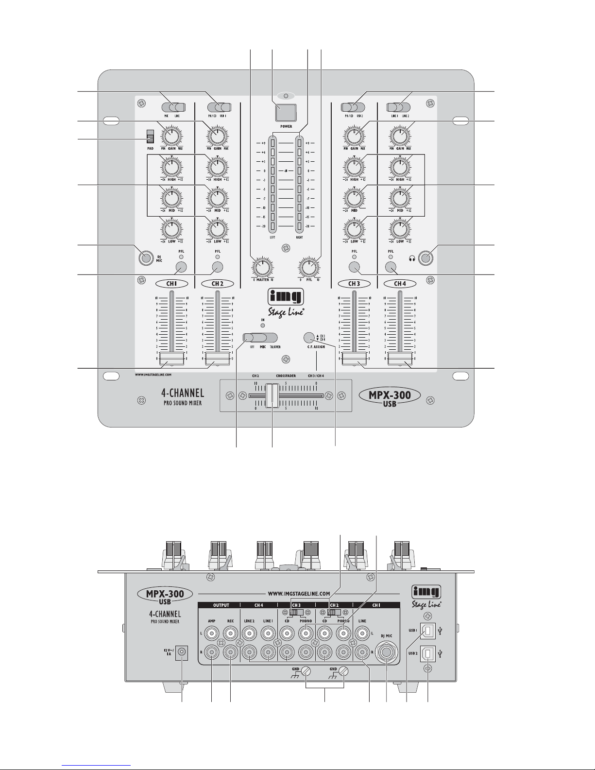
Bitte klappen Sie die Seite 3 heraus. Sie sehen
dann immer die beschriebenen Bedien elemente
und Anschlüsse.
1 Übersicht der Bedienelemente und
Anschlüsse
1.1 Frontseite
1 Pegelregler für das Mastersignal am Ausgang
AMP (19)
2 Ein-/Ausschalter (mit Betriebsanzeige)
3 LED-Pegelanzeige für das Stereo-Mastersignal
4 Pegelregler für das PFL-Signal am Kopfhörer-
ausgang (10)
5 Eingangswahlschalter für die Kanäle 1 – 4:
Kanal 1:
MIC Eingang DJ MIC auf der Frontplatte
bzw. auf der Rückseite
LINE Eingang LINE
Kanal 2:
PH/ CD Eingang CD oder PHONO (abhängig
von der Stellung des darüber
liegenden Um schalters)
USB 1 USB-Anschluss 1
Kanal 3:
PH/ CD Eingang CD oder PHONO (abhängig
von der Stellung des darüber
liegenden Um schalters)
USB 2 USB-Anschluss 2
Kanal 4:
LINE 1 Eingang LINE 1
LINE 2 Eingang LINE 2
6 Gain-Regler zum Einstellen der Eingangsver-
stärkung für die Kanäle 1 – 4
7 PAD-Schalter für den Mikrofoneingang [(9) oder
(23)] von Kanal 1: bei nach unten geschobenem
Schalter wird der Pegel des Mikrofons um 10 dB
abgesenkt
8 3fache Klangregelung für die Kanäle 1 – 4:
HIGH = Höhen, MID = Mitten, LOW = Bässe
9 6,3-mm-Klinkenbuchse (asym.) für den An schluss
eines Mikrofons; alternativ zur Buchse DJ MIC
(23) auf der Rückseite
10 6,3-mm-Klinkenbuchse zum Anschluss eines
Stereo-Kopfhörers (Impedanz ≥ 8 Ω)
11 PFL-Tasten (mit Kontroll-LEDs) für die Kanäle
1 – 4: zum Vorhören (Pre Fader Listening) des
jeweiligen Kanals über einen an der Buchse
(10) angeschlossenen Kopfhörer
12 Pegelregler (Fader) für die Kanäle 1 – 4
13 Umschalter (mit Kontroll-LED) für ein ange-
schlossenes Mikrofon
linke Position („OFF“), Kontroll-LED aus
das Mikrofon ist ausgeschaltet
mittlere Position („ON“), Kontroll-LED an
das Mikrofon ist eingeschaltet
rechte Position („TALKOVER“), Kontroll-LED an
das Mikrofon ist eingeschaltet und die Talk over-Funktion aktiviert: automatische Pegel ab senkung (16 dB) der Ka näle 2–4 bei Mikrofondurchsagen
14 Crossfader zum Überblenden zwischen Kanal 2
und Kanal 3 oder Kanal 4 [abhängig von der
Taste C.F. ASSIGN (15)]
15 Zuordnungstaste C.F. ASSIGN zur Auswahl von
Ka nal 3 (Taste nicht gedrückt) oder Kanal 4
(Taste gedrückt) für die Überblendfunktion
1.2 Rückseite
16 Umschalter CD/ PHONO, jeweils für Kanal 2 und
Kanal 3, zur Wahl zwischen dem Eingang CD
und dem Eingang PHONO
17 Stereo-Eingänge PHONO (Cinch) für die Ka näle
2 und 3 zum Anschluss von Plattenspielern mit
Mag netsystem
18 Anschluss für die Stromversorgung (12 V~/ 1 A)
über das beiliegende Steckernetzgerät
19 Stereo-Ausgang (Cinch) für den An schluss eines
Verstärkers
20 Stereo-Ausgang (Cinch) für den Anschluss eines
Tonaufnahmegerätes; der Aufnahmepegel ist un abhängig von der Stel lung des Masterreglers (1)
21 Masse-Klemmschrauben GND für an den Ka -
nälen 2 und 3 angeschlosse ne Plattenspieler
22 Stereo-Eingänge LINE und CD (Cinch) für die
Ka näle 1 – 4 zum Anschluss von Geräten mit
Line-Pegel-Ausgängen (z. B. MiniDisc-Recorder,
CD-Player)
23 6,3-mm-Klinkenbuchse (asym.) für den An schluss
eines Mikrofons; alternativ zur Buchse DJ MIC (9)
auf der Frontplatte
24 USB-Anschluss 1 (Typ B) zur Verbindung mit
einem Computer; kann gleich zeitig als Ausgang
(digitale Ausgabe des Ausgangssignals nach
dem Masterregler) und als Eingang (Einspeisen
von digitalen Audiosignalen zur Wiedergabe
über Kanal 2) genutzt werden
25 USB-Anschluss 2 (Typ B) zur Verbindung mit
einem Computer; kann gleich zeitig als Ausgang
(digitale Ausgabe des Ausgangssignals vor dem
Masterregler) und als Eingang (Einspeisen von
digitalen Audiosignalen zur Wiedergabe über
Kanal 3) ge nutzt werden
Please unfold page 3. Then you will always see
the operating elements and connections de scribed.
1 Operating Elements and Connections
1.1 Front panel
1 Level control for the master signal at the output
AMP (19)
2 Power switch (with power LED)
3 LED VU-meter for the stereo master signal
4 Level control for the PFL signal at the head-
phone output (10)
5 Input selector switches for channels 1 to 4:
Channel 1:
MIC input DJ MIC on the front panel or on
the rear panel
LINE input LINE
Channel 2:
PH/ CD input CD or PHONO (depending on
the position of the selector switch
above it)
USB 1 USB port 1
Channel 3:
PH/ CD input CD or PHONO (depending on
the position of the selector switch
above it)
USB 2 USB port 2
Channel 4:
LINE 1 input LINE 1
LINE 2 input LINE 2
6 Gain controls for adjusting the input amplification
for channels 1 to 4
7 PAD switch for the microphone input [(9) or (23)]
of channel 1: with the switch in the lower position, the level of the microphone will be attenu ated by 10 dB
8 3-way equalizer for channels 1 to 4:
HIGH, MID, LOW
9 6.3 mm jack (unbal.) for connecting a micro-
phone; as an alternative to the jack DJ MIC (23)
on the rear panel
10 6.3 mm jack for connecting stereo headphones
(impedance ≥ 8 Ω)
11 PFL switches (with indicating LEDs) for channels
1 to 4: for pre-fader listening to the correspond ing channel via headphones connected to the
jack (10)
12 Level controls (faders) for channels 1 to 4
13 Selector switch (with indicating LED) for a micro-
phone connected
left position (“OFF”), indicating LED off
the microphone is switched off
mid-position (“ON”), indicating LED on
the microphone is switched on
right position (“TALKOVER”), indicating LED on
the microphone is switched on and the talkover
feature is activated: automatic level attenuation
(16 dB) of channels 2 to 4 in case of microphone announcements
14 Crossfader for crossfading between channel 2
and channel 3 or channel 4 [depending on the
button C.F. ASSIGN (15)]
15 Button C.F. ASSIGN for selecting channel 3 (but-
ton not pressed) or channel 4 (button pressed)
for crossfading
1.2 Rear panel
16 Selector switches CD/ PHONO, each for channel
2 and channel 3, for selecting either input CD or
input PHONO
17 Stereo inputs PHONO for channels 2 and 3 for
connecting turntables with magnetic system
18 Connection for power supply (12 V~/ 1 A) via the
power supply unit supplied
19 Stereo output (phono jacks) for connect ing an
amplifier
20 Stereo output (phono jacks) for connecting an
audio recorder; the recording level is independ ent of the position of the master control (1)
21 Ground clamping screws GND for turntables
connected to channels 2 and 3
22 Stereo inputs LINE and CD (phono jacks) for
channels 1 to 4 for connecting units with line
level outputs (e. g. minidisk recorder, CD player)
23 6.3 mm jack (unbal.) for connecting a micro-
phone; as an alternative to the jack DJ MIC (9)
on the front panel
24 USB port 1 (type B) for connection to a com -
puter; can be used simultaneously as an output
(digital output of the output signal after the
master control) and as an input (feed-in of digital
audio signals for reproduction via channel 2)
25 USB port 2 (type B) for connection to a com -
puter; can be used simultaneously as an output
(digital output of the output signal ahead of the
master control) and as an input (feed-in of digital
audio signals for reproduction via channel 3)
4
GB
D
A
CH
2 Hinweise für den sicheren Gebrauch
Die Geräte (Mischpult und Steckernetzgerät) entsprechen allen erforder lichen Richt linien der EU und
sind deshalb mit gekennzeichnet.
Beachten Sie auch unbedingt die folgenden Punkte:
●
Die Geräte sind nur zur Verwendung im Innenbereich geeignet. Schützen Sie sie vor Tropf- und
Spritz wasser, hoher Luftfeuchtigkeit und Hit ze
(zulässiger Einsatztemperaturbereich 0 – 40 °C).
●
Stellen Sie keine mit Flüssigkeit gefüllten Gefäße,
z. B. Trinkgläser, auf die Geräte.
●
Nehmen Sie das Mischpult nicht in Betrieb bzw.
ziehen Sie sofort das Netzgerät aus der Steckdose, wenn:
1. sichtbare Schäden am Mischpult oder am Netzgerät vorhanden sind,
2. nach einem Sturz oder Ähnlichem der Verdacht
auf einen Defekt besteht,
3. Funktionsstörungen auftreten.
Lassen Sie die Geräte in jedem Fall in einer Fachwerkstatt reparieren.
●
Verwenden Sie zum Reinigen nur ein trockenes,
weiches Tuch, niemals Wasser oder Chemikalien.
●
Werden die Geräte zweckentfremdet, nicht richtig
angeschlossen, falsch bedient oder nicht fachge recht re pa riert, kann keine Garantie für die Geräte
und keine Haftung für daraus resultierende Sachoder Personenschäden übernommen werden.
3 Einsatzmöglichkeiten
Das 4-Kanal-Mischpult MPX-300USB ist für beliebi ge DJ-An wendungen im privaten oder professionel len Be reich geeignet. Zum Anschluss an einen
Com puter besitzt das Mischpult eine USB-AudioSchnittstelle (USB 1.1 kompatibel). Die zwei USBAnschlüsse arbeiten im Vollduplex-Betrieb: jeder
An schluss kann gleichzeitig als Ausgang (zur digitalen Ausgabe des Mischsignals an den Computer)
und als Eingang (zur Übertragung von Audio dateien
vom Computer zum Mischpult) ge nutzt werden. Für
den Betrieb des Mischpults mit dem Computer kann
die mit dem Betriebssystem mitgelieferte AudioSoftware verwendet werden oder eine zusätzlich
installierte Audio-Software. Verschiedene AudioWie dergabe- und -Aufnahmeprogramme sind als
Freeware im Internet e r hältlich.
Das Mischpult bietet Anschlussmöglichkeiten für
bis zu fünf Geräte mit Line-Pegel (z. B. CD-Player),
bis zu zwei Plattenspieler und ein Mikrofon. Alle Tonquellen lassen sich über einen Kopfhörer vorhören
(Pre Fader Listening).
4 Inbetriebnahme
Das Mischpult kann sowohl frei aufgestellt als auch
in ein Bedienpult eingebaut werden. Vor dem An schluss von Tonquellen darauf achten, dass alle
Geräte ausgeschaltet sind.
4.1 Tonquellen und Kopfhörer anschließen
1) Die Stereo-Tonquellen an die entsprechenden
Cinch-Eingangsbuchsen der Kanäle 1 – 4 an -
schlie ßen (weiße Buchse L = linker Kanal; rote
Buchse R = rechter Kanal):
– Geräte mit Line-Pegel-Ausgang (wie z. B. CD-
Player, MiniDisc-Recorder, Kassettenrecorder)
an die Buchsen LINE oder CD (22);
– Plattenspieler mit Magnetsystem an die Buch-
sen PHONO (17). Ist am Anschlusskabel des
Plat ten spielers ein separates Massekabel vorhanden, dieses mit der jeweiligen Klemmschraube GND (21) verbinden.
2) Ein Mikrofon an Kanal 1 – entweder an die
6,3-mm-Klin ken buch se DJ MIC (9) auf der Frontplatte oder an die 6,3-mm-Klinken buch se DJ MIC
(23) auf der Rückseite – anschlie ßen.
3) Alle Eingangskanäle 1 –4 lassen sich über einen
Stereo-Kopfhörer (Impedanz ≥ 8 Ω) vor den
Fadern (12) abhören (PFL = Pre Fader Listening,
→ Kapitel 5.5 „Vorhören der Kanäle“). Den Kopfhörer an die Buchse (10) an schlie ßen.
4.2 Verstärker und Aufnahmegerät
anschließen
Den Endverstärker an den Stereo-Ausgang AMP
(19) anschlie ßen.
Ein Tonaufnahmegerät kann an den Stereo-Aus-
gang REC (20) angeschlossen werden. Der Auf nahmepegel ist unabhängig von der Stellung des
Masterreglers (1).
Hinweis: Ist das Mischpult sowohl mit einem Com -
puter (→ Ka pi tel 4.4) als auch mit Geräten
verbunden, die über das Netz ka bel geerdet sind (z. B. Verstärker), können aufgrund von Masseschleifen Brummstö rungen auftreten. Um diese Störungen zu
beseitigen, kann das Mischpult über ein
Massetrennfilter (z. B. FGA-102 aus dem
Programm von „img Stage Line“) mit dem
jeweiligen Gerät verbunden werden.
4.3 Stromversorgung anschließen
Das Steckernetzgerät mit der Buchse (18) für die
Stromversorgung (12 V~/ 1 A) verbinden und in eine
Steckdose (230 V~/ 50 Hz) stecken.
WARNUNG Das Netzgerät wird mit lebensgefähr-
licher Netzspannung (230 V~) ver sorgt. Neh men Sie deshalb nie selbst
Eingriffe am Gerät vor. Durch un sach ge mäßes Vorgehen besteht die
Gefahr eines elektrischen Schlages.
Sollen die Geräte endgültig aus dem Be trieb ge nom men werden, übergeben Sie
sie zur umweltgerechten Entsorgung ei nem örtlichen Re cyc ling be trieb.
2 Safety Notes
The units (mixer and plug-in power supply unit) correspond to all required directives of the EU and are
therefore marked with .
Please observe the following items in any case:
●
The units are suitable for indoor use only. Protect
them against dripping water and splash water,
high air humidity, and heat (admissible ambient
temperature range 0 – 40 °C).
●
Do not place any vessel filled with liquid on the
unit, e. g. a drinking glass.
●
Do not operate the mixer and immediately disconnect the power supply unit from the mains
socket
1. if there is visible damage to the mixer or to the
power supply unit,
2. if a defect might have occurred after the unit
was dropped or suffered a similar accident,
3. if malfunctions occur.
In any case the units must be repaired by skilled
personnel.
●
For cleaning only use a dry, soft cloth; never use
chemicals or water.
●
No guarantee claims for the units and no liability
for any resulting personal damage or material
damage will be accepted if the units are used for
other purposes than originally intended, if they are
not correctly connected or operated, or not re paired in an expert way.
3 Applications
The 4-channel mixer MPX-300USB is suitable for any
private or professional DJ applications. For connection to a computer, it is equipped with a USB audio
interface (USB 1.1 compatible). The two USB ports
operate in full duplex mode, i. e. each port may be
simultaneously used as an output (for digital output of
the mixed signal to the computer) and as an input (for
transmitting audio files from the computer to the
mixer). For operating the mixer with the computer,
use the audio software supplied with the oper ating
system or an audio software installed additionally.
Various audio reproduction and recording pro grammes are available as freeware on the Internet.
The mixer allows connection of up to five units
with line level (e. g. CD player), up to two turntables,
and a microphone. The unit offers pre-fader listening
to all audio sources via headphones.
4 Setting the Mixer into Operation
The mixer can either be placed as desired or in stalled into a console. Prior to connecting any
audio sources, make sure that all units have been
switched off.
4.1 Connecting audio sources and head -
phones
1) Connect the stereo audio sources to the corre-
sponding phono input jacks of channels 1 to 4
(white jack L = left channel; red jack R = right
channel):
– units with line level output (e. g. CD player,
minidisk recorder, cassette recorder) to the
jacks LINE or CD (22);
– turntables with magnetic system to the jacks
PHONO (17). If the connection cable of the
turntable is provided with a separate ground
cable, connect this cable to the corresponding
clamping screw GND (21).
2) Connect a microphone to channel 1 – either to
the 6.3 mm jack DJ MIC (9) on the front panel or
to the 6.3 mm jack DJ MIC (23) on the rear panel.
3) All input channels 1 – 4 can be monitored via ster eo headphones (impedance ≥ 8 Ω) ahead of the
faders (12) [PFL = pre-fader listening; → chapter 5.5 “Pre-fader listening to the channels”].
Connect the headphones to the jack (10).
4.2 Connecting an amplifier and a recorder
Connect the power amplifier to the stereo output
AMP (19).
The stereo output REC (20) allows connection of
an audio recorder. The recording level is independ ent of the position of the master control (1).
Note: If the mixer is connected both to a computer
(→ chapter 4.4) and to units grounded via the
mains cable (e. g. amplifier), noise interfer ence may occur due to ground loops. To elim inate this interference, a ground isolator (e. g.
FGA-102 from the “img Stage Line” range)
may be used to connect the mixer to the
corresponding unit.
4.3 Connecting the power supply
Connect the plug-in power supply unit to the jack
(18) for the power supply (12 V~/1A) and to a mains
socket (230 V~/ 50 Hz).
If the units are to be put out of operation
definitively, take them to a local recycling
plant for a disposal which is not harmful to
the environment.
WARNING The power supply unit is supplied
with hazardous mains voltage
(230 V~). Leave servicing to skilled
personnel only. Inexpert handling
may cause an electric shock hazard.
5
GB
D
A
CH

4.4 Betrieb mit einem Computer
Über jeden der zwei USB-Anschlüsse können digitale
Au diosignale in beide Richtungen zwischen Mischpult
und Computer übertragen werden, auch gleichzeitig:
A Buchse USB 1 (24)
Verwendung als Eingang:
Über USB 1 eingespeiste Audiosignale können über Kanal 2 wiedergegeben werden.
Verwendung als Ausgang:
USB 1 gibt das Mastersignal aus [entspricht
dem Signal am Ausgang AMP (19)].
B Buchse USB 2 (25)
Verwendung als Eingang:
Über USB 2 eingespeiste Audiosignale können über Kanal 3 wiedergegeben werden.
Verwendung als Ausgang:
USB 2 gibt das Ausgangssignal vor dem Mas terregler aus [entspricht dem Signal am Ausgang REC (20)].
Die USB-Buchsen lassen sich nur in Verbindung mit
einem Computer nutzen. Wiedergabegeräte oder
Speichermedien mit USB-Anschluss können nicht
direkt mit dem Mischpult verbunden werden.
1) Den Computer (z. B. mit dem Betriebssystem
Windows 98 SE, Windows 2000, Windows XP
oder
Windows Vista
) und das Misch pult ein-
schalten.
2) Den jeweiligen USB-Anschluss des Mischpults
über ein USB-Verbindungskabel (z.B. über das
als Zubehör erhältliche Kabel USB-203AB) mit
einem USB-Anschluss am Computer verbinden:
Der USB-An schluss des Mischpults wird als
ex ter nes USB-Gerät erkannt, je nach Betriebs system des Computers z. B. als „USB Audio“,
„USB Audiogerät“ oder „USB Audio CODEC“ [mit
dem Zusatz „(2)“, wenn der Anschluss als zweites USB-Gerät installiert wurde]. Die erforder -
lichen Treiber (Standardtreiber des Betriebs sys tems) werden automatisch installiert.
Hinweis: Sind nicht alle geforderten Treiber auf
dem Computer vorhanden, muss wäh rend des Installationsvorgangs die
Betriebssystem-Original-CD eingelegt
oder eine Internetverbindung hergestellt werden, um die Treiber nachzu installieren. Gegebenenfalls nach der
Installation den Computer neu starten.
3) Die verwendete Abspiel-/Aufnahmesoftware aufrufen und dort die erforderlichen Einstellungen
für die Tonwiedergabe über das Mischpult
bzw. Tonaufnahme vom Mischpult vornehmen
(→ An lei tung der Software). Das Mischpult kann
dann an hand Kapitel 5 bedient werden.
Falls kein Ton zu hören ist, folgende Einstellungen
des Computer-Betriebssystems überprüfen:
– Toneingabe und -ausgabe müssen richtig zuge-
wiesen sein: Wird der jeweilige USB-Anschluss
des Mischpults als Eingang verwendet, muss er
als Wieder gabe ge rät angewählt sein, wird er als
Ausgang verwendet, muss er für die Tonaufnah me angewählt sein.
– Der Ton muss eingeschaltet sein.
– Die entsprechenden Lautstärkeregler dürfen nicht
auf Minimum eingestellt sein.
5 Bedienung
Erst den Masterregler (1) auf „0“ stellen, dann das
Mischpult mit dem Schalter POWER (2) einschalten.
Die Betriebsanzeige darüber leuchtet. Anschließend
die angeschlossenen Geräte einschalten.
Nach dem Betrieb das Mischpult wieder mit dem
Schalter POWER ausschalten. Wird es längere Zeit
nicht benutzt, das Steckernetz gerät aus der Steckdose ziehen, da es selbst bei aus ge schaltetem
Mischpult einen geringen Strom verbraucht.
5.1 Grundeinstellung der Eingangskanäle
Zu nächst alle Gain-Regler (6), Klangregler (8) und
den Crossfader (14) in die Mittelposition stellen.
Zum Einschalten des Mikrofons den Um schal ter
MIC (13) von der linken Position „OFF“ (Mi krofon
aus) in die mittlere Position „ON“ (LED über dem
Schalter leuchtet) kippen. Vorerst den Schalter PAD
(7) in die obere Position schieben.
Zum Aussteuern eines Kanals:
1) Mit dem Kippschalter (5) des Kanals den Ein-
gang anwählen, an dem die Tonquelle ange-
schlossen ist.
Bei den Kanälen 2 und 3 kann zwischen
drei Eingängen – PHONO, CD und USB 1 bzw.
USB 2 – umgeschaltet werden:
– Um den USB-Anschluss zu wählen, den Kipp-
schalter auf „USB 1“ bzw. „USB2“ stellen.
– Um den Eingang PHONO zu wäh len, den
Kippschalter auf „PH/ CD“ und den Schiebeschalter (16) des Kanals auf „PHONO“ stellen.
VORSICHT Stellen Sie die Lautstärke der Audio -
an lage und die Kopfhörerlautstärke
nie sehr hoch ein. Hohe Laut stärken
können auf Dauer das Gehör schädigen! Das Ohr gewöhnt sich an große
Lautstärken und empfindet sie nach
ei niger Zeit als nicht mehr so hoch.
Darum eine hohe Laut stärke nach
der Gewöhnung nicht wei ter erhöhen.
4.4 Operation with a computer
Each of the two USB ports allows transmission of
digital audio signals in both directions between the
mixer and the computer, even at the same time.
A port USB 1 (24)
when used as an input:
Audio signals fed in via USB 1 can be repro duced via channel 2.
when used as an output:
USB 1 will provide the master signal [corresponds to the signal at the output AMP (19)].
B port USB 2 (25)
when used as an input:
Audio signals fed in via USB 2 can be repro duced via channel 3.
when used as an output:
USB 2 will provide the output signal ahead of
the master control [corresponds to the signal
at the output REC (20)].
The USB ports can only be used in connection with
a computer. It will not be possible to directly connect
reproduction units or storage media with USB port to
the mixer.
1) Switch on the computer (e. g. with the operating
system
Windows 98 SE, Windows 2000, Win-
dows XP,
or
Windows Vista
) and the mixer.
2) Connect the corresponding USB port of the mixer
via a USB connection cable (e. g. via the cable
USB-203AB available as an accessory) to the
USB port on the computer:
The USB port of the mixer will be recognized
as an external USB unit; according to the oper ating system of the computer e. g. as “USB
Audio”, “USB Audio Device”, or “USB Audio
CODEC” [with the addition “(2)” if the port has
been in stalled as a second USB unit]. The drivers
re quired (standard drivers of the operating
system) will be installed automatically.
Note: If not all drivers required are available on
the computer, in order to install the drivers,
insert the original CD of the operating
system or make a connection to the Internet during installation. Restart the com puter after installation, if necessary.
3) Call the reproduction /recording software to make
the required adjustments for the audio reproduction via the mixer or for audio recording from the
mixer (→ software instructions). It will then be
possible to operate the mixer according to chapter 5.
If there is no sound, check the following adjustments of the operating system of the computer:
– Audio input and output must be correctly as -
signed: If the corresponding USB port of the
mixer is used as an input, it must be selected as
a reproduction unit; if it is used as an output, it
must be selected for audio recording.
– The sound must be switched on.
– The corresponding volume controls must not be
set to minimum.
5 Operation
Prior to switching on, set the master control (1) to
“0”, then switch on the mixer with the switch
POWER (2). The power LED above the switch will
light up. Then switch on the units connected.
After operation, switch off the mixer with the switch
POWER. If the mixer is not used for a longer period,
disconnect the plug-in power supply unit from the
mains socket as it will have a low power consumption even with the mixer switched off.
5.1 Basic adjustment of the input channels
First set all gain controls (6), equalizer controls (8),
and the crossfader (14) to mid-position.
To switch on the microphone, set the selector
switch MIC (13) from the left position “OFF” (microphone off) to mid-position “ON” (LED above the
switch will light up). For the time being, set the
switch PAD (7) to the upper position.
Level control of a channel:
1) Use the selector switch (5) of the channel to se -
lect the input to which the audio source is
connected.
For channels 2 and 3, three inputs are availa-
ble: PHONO, CD, and USB 1 or USB 2.
– To select the USB port, set the selector switch
to “USB 1” or “USB 2”.
– To select the input PHONO, set the selector
switch to “PH/ CD” and the sliding switch (16)
of the channel to “PHONO”.
CAUTION Never adjust the audio system and
headphones to a very high volume.
Permanent high volumes may dam age your hearing! The human ear will
get accustomed to high volumes
which do not seem to be that high
after some time. Therefore, do not
further increase a high volume after
getting used to it.
6
GB
D
A
CH
Windows ist ein registriertes Warenzeichen der Microsoft
Cor poration in den USA und anderen Ländern.
Windows is a registered trademark of Microsoft Corporation in the
U.S.A. and other countries.

– Um den Eingang CD zu wäh len, den Kipp-
schalter auf „PH/ CD“ und den Schiebeschalter
(16) des Kanals auf „CD“ stellen.
2) Mit dem Masterregler (1) wird der Ge samtpegel
aller angeschlossenen Tonquellen eingestellt.
Den Regler auf ca.
2
/3 des Maximums stellen.
3) Ein Tonsignal (Testsignal oder Musikstück) auf
den Kanal geben. Die Geräte, die auf den
anderen Ka nälen spielen sollen, ausschalten
bzw. auf Pau se stellen.
4) Anhand der LED-Pegelanzeige (3) mit dem
Fader (12) den Pegel des Kanals einstellen. Op ti male Aussteuerung liegt vor, wenn bei lauten
Passagen Pegelwerte im 0-dB-Bereich an ge zeigt werden. Leuchten die roten LEDs der Pe gelanzei ge auf, ist der Kanal übersteuert.
Der Fader sollte nach der Pegeleinstellung auf
ca.
2
/3 des Maximums stehen. Ist er sehr wenig
oder sehr weit aufgezogen, muss der Pegel durch
Regulierung der Eingangsverstärkung angepasst
werden: Den Gain-Regler (6) des Kanals entspre chend zu - bzw. aufdrehen (falls erforderlich, kann
der Gain-Regler auch ganz auf „MIN“ bzw. „MAX“
gedreht werden). Für das Mikrofon an Kanal 1
lässt sich ein zu hoher Eingangspegel zusätzlich
mit dem PAD-Schalter (7) um 10dB absenken:
den Schalter in die untere Position schieben.
5) Mit den drei Klangreglern (8) des Kanals das ge wünschte Klangbild einstellen. Durch Verstellen
der Regler lassen sich die Höhen (Regler HIGH),
Mitten (Regler MID) und Bässe (Regler LOW) an he ben (max. 12 dB) bzw. stark absenken (max.
26 dB). Bei Mittelstellung eines Klangreglers wird
der jeweilige Frequenzbereich nicht beeinflusst.
Hinweis: Klangeinstellungen wirken sich auf den
Pegel aus. Deshalb danach den Kanalpegel anhand der Pegelanzeige kontrollieren und ggf. korrigieren.
6) Die Pegel- und Klangeinstellung für die übrigen
belegten Eingangskanäle in der oben beschriebenen Weise durchführen.
5.2 Überblenden zwischen zwei Kanälen
Mit dem Crossfader (14) kann zwi schen Kanal 2
(fest zugeordnet) und Kanal 3 oder Kanal 4 [über
die Taste C.F. ASSIGN (15) wählbar] übergeblendet
werden.
1) Mit der Taste C.F. ASSIGN (15) entweder Kanal 3
oder Kanal 4 für die Überblendfunktion auswählen:
Taste nicht gedrückt: Kanal 3
Taste gedrückt: Kanal 4
2) Den ausgewählten Kanal und Kanal 2 optimal
aussteuern (→ Kapitel 5.1 „Grundeinstellung der
Eingangskanäle”).
3) Sollen die Stereo-Tonquellen an den übrigen
zwei Kanälen nicht zu hören sein, diese ausschalten bzw. auf Pause stellen oder ihre Kanalfader ganz zuziehen.
4) Nun kann mit dem Crossfader zwischen den
beiden Ka nälen übergeblendet werden:
Zum Einblenden von Kanal 2/Ausblenden von
Ka nal 3 oder 4 den Crossfader nach links
schie ben.
Zum Einblenden von Kanal 3 oder 4/Ausblen den von Ka nal 2 den Crossfader nach rechts
schieben.
Steht der Crossfader in der Mitte, werden bei de Kanäle gleichzeitig auf die Ausgänge gegeben.
5) Mit dem Masterregler (1) anhand der Pegelan zei ge (3) den ge wünschten Pe gel für den Ausgang
AMP (19) einstellen.
In der Regel wird eine optimale Aussteuerung
er reicht, wenn die Pegelanzeige bei lauten Passagen Werte im 0-dB-Bereich an zeigt. Ist der
Aus gangspegel jedoch für das nachfolgende Ge rät zu hoch oder zu niedrig, muss das Mastersignal entsprechend niedriger oder höher ausgesteuert werden.
5.3 Mischen der angeschlossenen Tonquellen
1) Den Crossfader (14) in die Mittelposition schieben.
2) Mit den Fadern (12) der Eingangskanäle das ge wünschte Lautstärkeverhältnis der Tonquellen
einstellen: Die Tonquellen, die am lautesten zu
hören sein sollen, optimal aussteuern (→ Kapitel
5.1) und die Pegel der übrigen Tonquellen entsprechend reduzieren.
Wird ein Kanal nicht be nutzt, sollte sein Fader
auf Minimum ge stellt werden.
3) Anhand der Pegel-Anzeige (3) mit dem Masterregler (1) den Pegel des Mischsignals einstellen
(→ Kapitel 5.2, Punkt 5).
5.4 Durchsagen über das Mikrofon
Zum Ein- und Ausschalten des Mikrofons an Kanal 1
sowie zum Aktivieren der Talkover-Funktion, den
Um schalter MIC (13) in die entsprechende Position
stellen:
1. Bei nach links gekipptem Schalter („OFF“) ist das
Mikrofon ausgeschaltet.
2. In der Mittelstellung („ON“) ist das Mikrofon eingeschaltet (LED über dem Schalter leuchtet).
3. Bei nach rechts gekipptem Schalter („TALK OVER“) ist das Mikrofon eingeschaltet und die
Talkover-Funk tion aktiviert (LED über dem
Schalter leuch tet): Während einer Mikrofondurchsage werden die Pe gel der Ka näle 2 – 4
automatisch um 16 dB ab gesenkt.
5.5 Vorhören der Kanäle
Über die Vorhörfunktion PFL (Pre Fader Listening =
Ab hören eines Kanals vor dem Kanalfader) ist es
möglich, jeden der Eingangskanäle 1 – 4 über einen
an der Buchse (10) angeschlossenen Kopfhörer
abzuhören, auch wenn der jeweilige Ka nal ausgeblendet ist. Dadurch kann z. B. auf einer CD der ge wünschte Titel ausgewählt oder der richtige Zeit-
– To select the input CD, set the selector switch
to “PH/ CD” and the sliding switch (16) of the
channel to “CD”.
2) With the master control (1), the total level of all
audio sources connected is adjusted. Set the
control to approx.
2
/3 of its maximum.
3) Feed an audio signal (test signal or music piece)
to the channel. Switch off the units intended to
play on the other channels or set them to pause.
4) Via the LED VU-meter (3), control the level of the
channel with the fader (12). An optimum level
control is obtained if level values in the 0 dB range
are shown at high volume. If the red LEDs of the
VU-meter light up, the channel is overloaded.
After level adjustment, the fader should be at
approx. 2/3 of its maximum. With the fader ad vanced only slightly or very far, the level must be
matched by adjusting the input amplification:
Turn up or turn back the gain control (6) of the
channel accordingly (if required, the gain control
can also be fully turned to “MIN” or “MAX”). For
the microphone connected to channel 1, an input
level which is too high can additionally be
attenuated by 10 dB with the PAD switch (7): set
the switch to the lower position.
5) Use the three equalizer controls (8) of the channel to adjust the desired sound. By adjusting the
controls, the high frequencies (control HIGH),
the midrange frequencies (control MID), and the
low frequencies (control LOW) can be boosted
(12 dB max.) or substantially attenuated (26 dB
max.) With a control in mid-position, the corresponding frequency range will not be affected.
Note: Sound adjustments will affect the level.
Therefore, after adjusting the sound,
check the channel level by means of the
VU-meter and readjust it, if required.
6) Make the level and sound adjustments for the
other input channels connected as described
above.
5.2 Crossfading between two channels
The crossfader (14) allows crossfading between
channel 2 (firmly assigned) and channel 3 or chan-
nel 4 [to be selected via the button C.F. ASSIGN
(15)].
1) Use the button C.F. ASSIGN (15) to select either
channel 3 or channel 4 for crossfading:
button not pressed: channel 3
button pressed: channel 4
2) Control the channel selected and channel 2 to an
optimum level (→ chapter 5.1 “Basic adjustment
of the input channels”).
3) If desired, suppress the stereo audio sources at
the other two channels: switch them off, set them
to pause, or completely close their channel
faders.
4) Now crossfading between the two channels is
possible:
To fade in channel 2/fade out channel 3 or 4,
slide the crossfader to the left.
To fade in channel 3 or 4/fade out channel 2,
slide the crossfader to the right.
With the crossfader in mid-position, both channels will be simultaneously fed to the outputs.
5) Via the VU-meter (3), adjust the desired level for
the output AMP (19) with the master control (1).
Usually an optimum level control is obtained if
the VU-meter shows values in the 0 dB range at
high volume. However, if the output level is too
high or too low for the following unit, control the
master signal accordingly to a lower or higher
level.
5.3 Mixing the audio sources connected
1) Slide the crossfader (14) to mid-position.
2) Use the faders (12) of the input channels to
adjust the desired volume ratio of the audio sources: Adjust the audio sources to be heard at the
highest volume to an optimum level (→ chapter 5.1) and reduce the levels of the other audio
sources accordingly.
If a channel is not used, its level control should
be set to minimum.
3) Via the VU-meter (3), adjust the level of the
mixed signal with the master control (1) [→ chapter 5.2, point 5].
5.4 Announcements via the microphone
To switch on or off the microphone at channel 1 and
to activate the talkover feature, set the selector
switch MIC (13) to the corresponding position:
1. With the switch set to the left (“OFF”), the microphone is switched off.
2. In mid-position (“ON”), the microphone is switch ed
on (LED above the switch will light up).
3. With the switch set to the right (“TALKOVER”),
the microphone is switched on and the talkover
feature is activated (LED above the switch will
light up): During a microphone announcement,
the levels of channels 2 to 4 will be automatically
attenuated by 16 dB.
5.5 Pre-fader listening to the channels
The PFL feature (pre-fader listening = monitoring a
channel ahead of the channel fader) allows to monitor each of the input channels 1 to 4 via headphones
connected to the jack (10), even if the corresponding channel is faded out. Thus, it is possible,
e. g. to select the desired title on a CD or to time the
moment for fading in an audio source.
7
GB
D
A
CH

punkt zum Einblenden einer Tonquelle abgepasst
werden.
1) Zum Vorhören eines Kanals die dazugehörige
PFL-Taste (11) drücken; die darüber liegende
LED leuchtet.
2) Mit dem Regler PFL (4) die Kopf hörerlautstärke
einstellen.
6 Technische Daten
Anschlüsse
DJ MIC-Eingänge, mono
Empfindlichkeit/ Impedanz: 1,5 mV/2 kΩ
Buchsen: . . . . . . . . . . . . . 6,3-mm-Klinke, asym.
PHONO-Eingänge, stereo
Empfindlichkeit/ Impedanz: 3 mV/24 kΩ
Buchsen: . . . . . . . . . . . . . Cinch Links/Rechts
CD/ LINE-Eingänge, stereo
Empfindlichkeit/ Impedanz: 150 mV/50 kΩ
Buchsen: . . . . . . . . . . . . . Cinch Links/Rechts
AMP-Ausgang, stereo
Nennpegel/ Impedanz: . . . 1 V/ 600 Ω
Buchsen: . . . . . . . . . . . . . Cinch Links/Rechts
REC-Ausgang, stereo
Nennpegel/ Impedanz: . . . 0,5 V/ 600 Ω
Buchsen: . . . . . . . . . . . . . Cinch Links/Rechts
Kopfhörerausgang, stereo
Impedanz: . . . . . . . . . . . . . ≥ 8 Ω
Buchse: . . . . . . . . . . . . . . 6,3-mm-Klinke
USB, Vollduplex
Format: . . . . . . . . . . . . . . . USB 1.1 kompatibel
Buchsen: . . . . . . . . . . . . . Typ B
Allgemein
Frequenzbereich: . . . . . . . . 20 – 20 000Hz
Klirrfaktor: . . . . . . . . . . . . . . 0,1 %
Störabstand: . . . . . . . . . . . . 61 dB, unbewertet
Klangregelung für die
Tiefen: . . . . . . . . . . . . . . . . +12 dB,
-
26 dB / 50 Hz
Mitten: . . . . . . . . . . . . . . . . +12 dB, -26 dB / 1 kHz
Höhen: . . . . . . . . . . . . . . . . +12 dB, -26 dB / 10 kHz
Talkover: . . . . . . . . . . . . . . .
-
16 dB
Stromversorgung: . . . . . . . . 12 V~/ 1 A über bei -
lieg. Steckernetzgerät
(230 V~ / 50 Hz/20 VA)
Einsatztemperatur: . . . . . . . 0 –40 °C
Maße der Frontplatte: . . . . . 280 mm × 266 mm
Höhe: . . . . . . . . . . . . . . . . . 91 mm (ohne
Bedienelemen te)
Gewicht: . . . . . . . . . . . . . . . 3,3 kg
Änderungen vorbehalten.
1) For pre-fader listening to a channel, press the
corresponding PFL switch (11); the LED above it
will light up.
2) Adjust the desired headphone volume with the
control PFL (4).
6 Specifications
Connections
DJ MIC inputs, mono
Sensitivity/impedance: . . . 1.5 mV/2 kΩ
Jacks: . . . . . . . . . . . . . . . . 6.3 mm jacks, unbal.
PHONO inputs, stereo
Sensitivity/impedance: . . . 3 mV/24 kΩ
Jacks: . . . . . . . . . . . . . . . . phono jacks L / R
CD/ LINE inputs, stereo
Sensitivity/impedance: . . . 150 mV/50 kΩ
Jacks: . . . . . . . . . . . . . . . . phono jacks L / R
AMP output, stereo
Nominal level/ impedance: 1 V/600 Ω
Jacks: . . . . . . . . . . . . . . . . phono jacks L / R
REC output, stereo
Nominal level/ impedance: 0.5 V/600 Ω
Jacks: . . . . . . . . . . . . . . . . phono jacks L / R
Headphone output, stereo
Impedance: . . . . . . . . . . . . ≥ 8 Ω
Jack: . . . . . . . . . . . . . . . . . 6.3 mm jack
USB, full duplex
Format: . . . . . . . . . . . . . . . USB 1.1. compatible
Jacks: . . . . . . . . . . . . . . . . type B
General information
Frequency range: . . . . . . . . 20 –20 000 Hz
THD: . . . . . . . . . . . . . . . . . . 0.1 %
S/ N ratio: . . . . . . . . . . . . . . 61 dB, unweighted
Equalizer for the
low frequencies: . . . . . . . . +12 dB,
-
26 dB / 50 Hz
midrange frequencies: . . . +12 dB, -26 dB / 1 kHz
high frequencies: . . . . . . . +12 dB, -26 dB / 10 kHz
Talkover: . . . . . . . . . . . . . . .
-
16 dB
Power supply: . . . . . . . . . . . 12 V~/ 1 A via power
supply unit supplied
(230 V~ / 50 Hz/20 VA)
Ambient temperature: . . . . . 0 – 40 °C
Dimensions of front panel: . 280 mm × 266 mm
Height: . . . . . . . . . . . . . . . . 91 mm (without oper -
ating elements)
Weight: . . . . . . . . . . . . . . . . 3.3 kg
Subject to technical modification.
8
GB
D
A
CH
Diese Bedienungsanleitung ist urheberrechtlich für MONACOR®INTERNATIONAL GmbH & Co. KG
geschützt. Eine Reproduktion für eigene kommerzielle Zwecke – auch auszugsweise – ist untersagt.
All rights reserved by MONACOR®INTERNATIONAL GmbH & Co. KG. No part of this instruction manual
may be reproduced in any form or by any means for any commercial use.

Ouvrez le présent livret page 3 de manière à
visualiser les éléments et branchements.
1 Eléments et branchements
1.1 Face avant
1 Potentiomètre de réglage de niveau pour le si -
gnal master à la sortie AMP (19)
2 Interrupteur marche/ arrêt (avec témoin de fonc-
tionnement)
3 VU-mètre à LEDs pour le signal master stéréo
4 Potentiomètre de réglage de niveau pour le si -
gnal PFL à la sortie casque (10)
5 Sélecteurs dʼentrée pour les canaux 1 à 4
canal 1 :
MIC entrée DJ MIC sur la face avant ou
sur la face arrière
LINE entrée LINE
canal 2 :
PH/ CD entrée CD ou PHONO (dépend de la
position du sélecteur positionné audessus)
USB1 port USB 1
canal 3 :
PH/ CD entrée CD ou PHONO (dépend de la
position du sélecteur positionné audessus)
USB2 port USB 2
canal 4 :
LINE 1 entrée LINE 1
LINE 2 entrée LINE 2
6 Potentiomètres de réglage de gain pour
lʼamplification dʼentrée pour les canaux 1 à 4
7 Interrupteur PAD pour lʼentrée micro [(9) ou
(23)] du canal 1 : si lʼinterrupteur est poussé vers
le bas, le niveau du micro est diminué de 10 dB
8 Egaliseur 3 voies pour les canaux 1 à 4 :
HIGH (aigus), MID (médiums), LOW (graves)
9 Prise jack 6,35, (asym) pour brancher un micro ;
alternative à la prise DJ MIC (23) sur la face
arrière
10 Prise jack 6,35 pour brancher un casque stéréo
(impédance ≥ 8 Ω)
11 Touches PFL (avec LEDs de contrôle) pour les
canaux 1 à 4 : pour faire une préécoute (“Pre
Fader Listening”) du canal correspondant via un
casque relié à la prise (10)
12 Potentiomètres de réglage de niveau (faders)
pour les canaux 1 à 4
13 Sélecteur (avec LED de contrôle) pour un micro
relié
position gauche (“OFF”), LED de contrôle éteinte
micro éteint
position médiane (“ON”) , LED de contrôle
allumée
micro allumé
position droite (“TALKOVER”), LED de contrôle
allumée
micro allumé et fonction Talkover activée : diminution automatique de niveau (16 dB) des ca naux 2 à 4 en cas dʼannonces micro
14 Potentiomètre de fondu enchaîné (crossfader)
entre le canal 2 et le canal 3 ou le canal 4
[dépend de la touche C.F. ASSIGN (15)]
15 Touche dʼattribution C.F. ASSIGN pour choisir
entre canal 3 (touche non enfoncée) ou canal 4
(touche enfoncée) pour la fonction fondu
enchaîné.
1.2 Face arrière
16 Sélecteurs CD/ PHONO respectivement pour le
canal 2 et le canal 3, pour sélectionner entre
lʼentrée CD et lʼentrée PHONO
17 Entrées stéréo PHONO (RCA) pour les canaux 2
et 3 pour brancher des platines disques à
système magnétique
18 Branchement pour lʼalimentation (12 V~ / 1 A) via
le bloc secteur livré
19 Sortie stéréo (RCA) pour brancher un amplifica-
teur
20 Sortie stéréo (RCA) pour brancher un enregis -
treur audio : le niveau dʼenregistrement est indépendant de la position du réglage master (1)
21 Bornes à vis de masse GND pour des platines
disques reliées aux canaux 2 et 3
22 Entrées stéréo LINE et CD (RCA) pour les ca -
naux 1 à 4 pour relier des appareils à sorties
niveau ligne (par exemple enregistreur de mini
disques, lecteur CD).
23 Prise jack 6,35 femelle (asym) pour brancher un
micro ; alternative à la prise DJ MIC (9) sur la
face avant
24 Port USB 1 (type B) pour relier à un ordinateur :
peut simultanément être utilisé comme sortie
(sortie digitale du signal de sortie après le
réglage master) et comme entrée (insertion de
signaux audio digitaux pour une restitution via le
canal 2)
25 Port USB 2 (type B) pour relier à un ordinateur :
peut simultanément être utilisé comme sortie
(sortie digitale du signal de sortie avant le
réglage master) et comme entrée (insertion de
signaux audio digitaux pour une restitution via le
canal 3)
Vi preghiamo di aprire completamente la pagina 3.
Così vedrete sempre gli elementi di comando e i
collegamenti descritti.
1 Elementi di comando e collegamenti
1.1 Pannello frontale
1 Regolatore livello per il segnale master allʼuscita
AMP (19)
2 Interruttore on/ off (con spia di funzionamento)
3 LED di visualizzazione del livello per il segnale
master stereo
4 Regolatore livello per il segnale PFL allʼuscita
cuffia (10)
5 Selettore dʼingresso per i canali 1 – 4:
Canale 1:
MIC Ingresso DJ MIC sul pannello frontale
e/ o sul retro
LINE Ingresso LINE
Canale 2:
PH/ CD Ingresso CD o PHONO (a seconda
della posizione del selettore sovrastante)
USB 1 Porta USB 1
Canale 3:
PH/ CD Ingresso CD o PHONO (a seconda
della posizione del selettore sovrastante)
USB 2 Porta USB 2
Canale 4:
LINE 1 Ingresso LINE 1
LINE 2 Ingresso LINE 2
6 Regolatore Gain per impostare lʼamplificazione
allʼingresso per i canali 1 – 4
7 Interruttore PAD per lʼingresso microfono [(9) o
(23)] del canale 1: se spostato in basso, il livello
dʼingresso del microfono viene abbassato di
10 dB
8 Regolazione toni a 3 frequenze diverse per i
canali 1 – 4:
HIGH = acuti, MID = medi, LOW = bassi
9 Presa jack 6,3 mm (asimm.) per il collegamento
di un microfono; in alternativa alla presa DJ MIC
(23) sul retro
10 Presa jack 6,3 mm per il collegamento di una cuf-
fia stereo (impedenza ≥ 8 Ω)
11 Tasti PFL (con LED di controllo) per i canali 1– 4:
per il preascolto (pre fader listening) del relativo
canale mediante una cuffia collegata alla presa
(10)
12 Regolatore livello (fader) per i canali 1 – 4
13 Commutatore (con LED di controllo) per un
microfono collegato
posizione a sinistra (“OFF”), LED di controllo
spento:
il microfono è spento
posizione centrale (“ON”), LED di controllo
acceso:
il microfono è acceso
posizione a destra (“TALKOVER”), LED di controllo acceso:
il microfono è acceso e la funzione talkover è
attivata: abbassamento automatico del livello
(16 dB) dei canali 2 – 4 durante gli avvisi fatti
con il microfono
14 Crossfader per eseguire dissolvenze fra i canali
2 e 3 o 4 [a seconda della posizione del tasto
C.F. ASSIGN (15)]
15 Tasto di assegnazione C.F. ASSIGN per selezio-
nare il canale 3 (tasto non premuto) o 4 (tasto
premuto) per le dissolvenze
1.2 Pannello posteriore
16 Selettore CD/ PHONO, per i canali 2 e 3, per
scegliere fra ingresso CD e ingresso PHONO
17 Ingressi stereo PHONO (RCA) per i canali 2 e 3
per il collegamento di giradischi con sistema
magnetico
18 Presa per lʼalimentazione (12 V~ / 1 A) mediante
lʼalimentatore in dotazione
19 Uscita stereo (RCA) per il collegamento di un
amplificatore
20 Uscita stereo REC (RCA) per il collegamento di
un registratore; il livello di registrazione è indipendente dalla posizione del regolatore Master
(1)
21 Morsetti massa GND per giradischi collegati ai
canali 2 e 3
22 Ingressi stereo LINE e CD (RCA) per i canali
1 –4 per il collegamento di apparecchi con uscita
Line (p. es. registratore mini-disk, lettore CD)
23 Presa jack 6,3 mm (asimm.) per il collegamento
di un microfono; in alternativa alla presa DJ MIC
(9) sul pannello frontale
24 Porta USB 1 (tipo B) per il collegamento con un
computer; può essere usata sia come uscita
(output digitale del segnale dʼuscita a valle del
regolatore master), sia come ingresso (input di
segnali audio digitali per la riproduzione tramite il
canale 2)
25 Porta USB 2 (tipo B) per il collegamento con un
computer; può essere usata sia come uscita
(output digitale del segnale dʼuscita a monte del
regolatore master), sia come ingresso (input di
segnali audio digitali per la riproduzione tramite il
canale 3)
9
I
F
B
CH

2 Conseils de sécurité et dʼutilisation
Les appareils (table de mixage et le bloc secteur)
répondent à toutes les directives nécessaires de
lʼUnion européenne et portent donc le symbole .
Respectez scrupuleusement les points suivants :
●
Les appareils ne sont conçus que pour une utilisation en intérieur. Protégez les appareils des
éclaboussures, de tout type de projections dʼeau,
dʼune humidité élevée et de la chaleur (température ambiante admissible 0 – 40 °C).
●
En aucun cas, vous ne devez pas poser dʼobjet
contenant du liquide ou un verre sur lʼappareil.
●
Ne faites pas fonctionner la table de mixage et
débranchez le bloc secteur immédiatement dans
les cas suivants :
1. la table de mixage ou le bloc secteur présentent
des dommages visibles.
2. après une chute ou accident similaire, vous
avez un doute sur lʼétat de lʼappareil.
3. des dysfonctionnements apparaissent.
Dans tous les cas, les dommages doivent être
réparés par un technicien spécialisé.
●
Pour le nettoyage, utilisez un chiffon sec et doux,
en aucun cas de produits chimiques ou dʼeau.
●
Nous déclinons toute responsabilité en cas de
dommages corporels ou matériels résultants si la
table de mixage ou le bloc secteur sont utilisés
dans un but autre que celui pour lequel ils ont été
conçus, sʼils ne sont pas correctement branchés,
utilisés ou sʼils ne sont pas réparés par une personne habilitée ; en outre, la garantie deviendrait
caduque.
3 Possibilités dʼutilisation
La table de mixage 4 canaux MPX-300USB est spécialement conçue pour toute utilisation DJ dans le
domaine privé ou professionnel. La table de mixage
possède une interface audio USB (compatible USB
1.1) pour être branchée à un ordinateur. Les deux
ports USB fonctionnent en mode duplex intégral ;
chaque branchement peut être utilisé simultanément comme sortie (pour une sortie digitale du si gnal mixé vers lʼordinateur) et comme entrée (pour
une transmission de données audio de lʼordinateur
vers la table de mixage). Pour le fonctionnement de
la table de mixage avec lʼordinateur, le logiciel audio
livré avec le système dʼexploitation peut être utilisé
ou un autre logiciel audio installé en plus. Différents
programmes audio de lecture et dʼenregistrement
sont disponibles sur internet en freeware.
La table de mixage permet de brancher jusquʼà 5
appareils à niveau ligne (p. ex. lecteur CD), jusquʼà
deux platines disques et un microphone. Lʼappareil
permet de faire une préécoute de toutes les sources
audio via un casque (Pre Fader Listening).
4 Fonctionnement
La table de mixage peut être posée librement ou
placée dans un pupitre de commande. Avant
dʼeffectuer les branchements des sources audio,
veillez à ce que tous les appareils soient éteints.
4.1 Branchement des sources audio et du
casque
1) Reliez les sources audio stéréo aux prises
dʼentrée RCA correspondantes des canaux 1 à 4
(prise L blanche = canal gauche, prise R rouge =
canal droit) :
– appareils à sortie niveau ligne (par exemple
enregistreur MD, lecteur CD, magnétophone)
aux prises CD ou LINE (22) ;
– platines disques à système magnétique aux
prises PHONO (17). Si sur le cordon de liaison
de la platine disque, un câble de masse
distinct est prévu, reliez-le à la borne GND (21)
correspondante.
2) Reliez un microphone au canal 1 – soit à la prise
jack 6,35 DJ MIC (9) sur la face avant soit à la
prise jack 6,35 DJ MIC (23) sur la face arrière.
3) Il est possible de faire une préécoute de tous les
canaux dʼentrées 1 à 4 via un casque stéréo
(impédance ≥ 8 Ω) avant les faders (12) (PFL =
Pre Fader Listening, voir chapitre 5.5 “Préécoute
des canaux”). Reliez le casque à la prise (10).
4.2 Branchement dʼun amplificateur et dʼun
enregistreur
Reliez lʼamplificateur final à la sortie stéréo AMP
(19).
Un enregistreur audio peut être relié à la sortie
stéréo REC (20). Le niveau dʼenregistrement est
indépendant de la position du réglage master (1).
Conseil Si la table de mixage est reliée aussi bien
à un ordinateur (voir chapitre 4.4) quʼà des
appareils mis à la masse via le cordon secteur (par exemple amplificateur), des ronflements, générés par des bouclages de
masse peuvent apparaître. Pour éliminer
ces interférences la table de mixage peut
être reliée, via un filtre dʼisolation (par
exemple FGA-102 de la gamme “img
Stage Line”), à lʼappareil correspondant.
Lorsque les appareils sont définitivement
retirés du service, vous devez les déposer
dans une usine de recyclage adaptée pour
contribuer à leur élimination non polluante.
AVERTISSEMENT Le bloc secteur est alimenté
par une tension dangereuse
en 230 V~. Ne touchez jamais
lʼintérieur de lʼappareil car, en
cas de mauvaise manipulation, vous pouvez subir une
décharge électrique.
2 Avvertenze di sicurezza
Gli apparecchi (mixer e alimentatore a spina) sono
conformi a tutte le direttive richieste dellʼUE e pertanto portano la sigla .
Si devono osservare assolutamente anche i
seguenti punti:
●
Gli apparecchi sono adatti solo per lʼuso allʼinterno
di locali. Proteggerli dallʼacqua gocciolante e dagli
spruzzi dʼacqua, da alta umidità dellʼaria e dal calore
(temperatura dʼimpiego ammessa fra 0 e 40 °C).
●
Non depositare sugli apparecchi dei contenitori
riempiti di liquidi, p. es. bicchieri.
●
Non mettere in funzione il mixer e staccare subito
lʼalimentatore dalla rete se:
1. lʼapparecchio o lʼalimentatore presentano dei
danni visibili;
2. dopo una caduta o dopo eventi simili sussiste il
sospetto di un difetto;
3. lʼapparecchio non funziona correttamente.
Per la riparazione rivolgersi sempre ad una officina competente.
●
Per la pulizia usare solo un panno morbido,
asciutto; mai prodotti chimici o acqua.
●
Nel caso di uso improprio, di collegamenti sba gliati, di impiego scorretto o di riparazione non a
regola dʼarte degli apparecchi non si assume nessuna responsabilità per eventuali danni consequenziali a persone o cose e non si assume nessuna garanzia per gli apparecchi.
3 Possibilità dʼimpiego
Il mixer a 4 canali MPX-300USB è adatto per
impieghi DJ privati o professionali. Per il collegamento con un computer, il mixer è equipaggiato con
una interfaccia USB audio (compatibile USB 1.1). Le
due porte USB funzionano in modalità full duplex:
ogni porta può essere usata contemporaneamente
come uscita (output del segnale digitale al computer) e come ingresso (trasferimento di file audio dal
computer sul mixer). Per usare il mixer con il computer si può usare il software audio consegnato con
il sistema operativo oppure un altro software audio.
In Internet sono disponibili come freeware diversi
programmi per riproduzione e registrazione audio.
Il mixer offre la possibilità di collegare fino a 5
apparecchi con livello Line (p. es. lettori CD), fino a 2
giradischi e un microfono. Per tutte le sorgenti audio
esiste la possibilità di preascolto (pre fader listening)
tramite una cuffia.
4 Messa in funzione
Il mixer può essere collocato liberamente su un
piano o può essere inserito in un quadro di
comando. Prima di collegare le sorgenti audio controllare che tutti gli apparecchi siano spenti.
4.1 Collegare sorgenti audio e cuffia
1) Collegare le sorgenti stereo con le relative prese
RCA dʼingresso dei canali 1– 4 (presa bianca L =
canale di sinistra, presa rossa R = canale di
destra):
– apparecchi con livello Line (p. es. lettore CD,
registratore minidisk, registratore a cassette)
con le prese LINE o CD (22);
– giradischi con sistema magnetico con le prese
PHONO (17). Se il cavo di collegamento del
giradischi dispone di un cavo separato per la
massa, collegarlo con la relativa vite GND
(21).
2) Collegare un microfono con il canale 1 – o me diante la presa jack 6,3 mm DJ MIC (9) sul pannello frontale o con la presa jack 6,3 mm DJ MIC
(23) sul pannello posteriore.
3) Con una cuffia stereo (impedenza ≥ 8 Ω) è possibile il preascolto di tutti i canali dʼingresso 1 – 4 a
monte dei fader (12) (PFL = pre fader listening;
→ cap. 5.5 “Preascolto dei canali”). Collegare la
cuffia con la presa (10).
4.2 Collegare un amplificatore e un registratore
Collegare lʼamplificatore finale con lʼuscita stereo
AMP (19).
Allʼuscita stereo REC (20) si può collegare un
registratore. Il livello di registrazione è indipendente
dalla posizione del regolatore master (1).
N. B.: Se il mixer è collegato sia con un computer
(→ capitolo 4.4) che con degli apparecchi
collegati con la terra attraverso il loro cavo di
rete (p. es. un amplificatore), per via degli
anelli di massa si possono verificare dei ronzii. Per eliminare queste interferenze, il mixer
può essere collegato con detto apparecchio
per mezzo di un isolatore di massa (p. es.
FGA-102 del programma di “img Stage
Line”).
4.3 Collegamento dellʼalimentazione
Collegare lʼalimentatore a spina con la presa (18)
per lʼalimentazione (12 V~ / 1 A) e inserirlo in una
presa di rete (230 V~ / 50 Hz).
Se si desidera eliminare gli apparecchi
definitivamente, consegnarli per lo smaltimento ad unʼistituzione locale per il rici claggio.
AVVERTIMENTO Lʼalimentatore funziona con
pericolosa tensione di rete
(230 V~). Non intervenire mai al
suo interno; la manipolazione
scorretta può provocare delle
scariche pericolose.
10
I
F
B
CH

4.3 Branchement de lʼalimentation
Reliez le bloc secteur à la prise (18) pour
lʼalimentation (12 V~/1 A) et lʼautre extrémité du cordon à une prise secteur 230 V~ / 50 Hz.
4.4 Fonctionnement avec un ordinateur
Via chacun des deux ports USB, des signaux audio
digitaux peuvent être transmis dans les deux sens
entre la table de mixage et lʼordinateur, même simultanément :
A port USB 1 (24)
utilisation comme entrée :
Des signaux audio insérés via USB 1 peuvent
être restitués via le canal 2.
utilisation comme sortie :
USB 1 sort le signal master [correspond au
signal à la sortie AMP (19)].
B port USB 2 (25)
utilisation comme entrée :
Des signaux audio insérés via USB 2 peuvent
être restitués via le canal 3.
utilisation comme sortie :
USB 2 sort le signal de sortie avant le réglage
master [correspond au signal à la sortie REC
(20)].
Les ports USB ne peuvent être utilisés quʼen liaison
avec un ordinateur. Les appareils de restitution ou
les médias de stockage avec port USB ne peuvent
pas être directement reliés à la table de mixage.
1) Allumez lʼordinateur (par exemple avec système
dʼexploitation
Windows 98 SE, Windows 2000,
Windows XP
ou
Windows Vista
) et la table de
mixage.
2) Reliez le port USB correspondant de la table de
mixage via un cordon de liaison USB (par exemple via le cordon USB-203AB disponible en
option), à un port USB sur lʼordinateur.
Le port USB de la table de mixage est
reconnu comme appareil USB externe, selon le
système dʼexploitation de lʼordinateur par exemple comme “USB Audio”, “Appareil audio USB”
ou “CODEC Audio USB” [avec le supplément
“(2)” si le port a été installée comme second
appareil USB]. Les drivers nécessaires (drivers
standards du système dʼexploitation) sont
installés automatiquement.
Remarque : Si lʼordinateur ne dispose pas de
tous les drivers nécessaires, il faut,
pendant le processus dʼinstallation,
insérer le CD dʼorigine du système
dʼexploitation ou établir une con nexion internet pendant lʼinstallation,
pour installer les drivers. Le cas
échéant, redémarrez lʼordinateur
une fois lʼinstallation effectuée.
3) Appelez le logiciel de lecture /enregistrement utilisé et effectuez les réglages nécessaires pour la
restitution du son via la table de mixage ou pour
lʼenregistrement depuis la table de mixage (voir
notice du logiciel). La table de mixage peut
ensuite être utilisée selon les indications du chapitre 5.
Si aucun son nʼest audible, vérifiez les réglages
suivants du système dʼexploitation de lʼordinateur :
– Lʼentrée et la sortie audio doivent être correcte-
ment attribuées : si le port USB correspondant de
la table de mixage est utilisé comme entrée, il
doit être sélectionné comme appareil de lecture,
sʼil est utilisé comme sortie, il doit être sélectionné comme enregistreur.
– Le son doit être allumé.
– Les réglages de volume correspondants ne doi-
vent pas être réglés sur le minimum.
5 Fonctionnement
Avant dʼallumer la table, mettez le réglage master
(1) sur “0”, allumez ensuite la table de mixage avec
lʼinterrupteur POWER (2). Le témoin de fonctionnement au-dessus de lʼinterrupteur brille. Allumez
ensuite les appareils reliés.
Après le fonctionnement, éteignez la table avec
lʼinterrupteur POWER : en cas de non-utilisation
prolongée, débranchez le bloc secteur, car même si
la table est éteinte, le bloc secteur a une faible consommation.
5.1 Réglage de base des canaux dʼentrée
Mettez lʼensemble des réglages gain (6), réglages
de lʼégaliseur (8) et le crossfader (14) sur la position
médiane.
Pour allumer le micro, poussez le sélecteur MIC
(13) de la position gauche “OFF”(micro éteint) sur la
position médiane “ON” (la LED au-dessus de
lʼinterrupteur brille). Poussez tout dʼabord lʼinter rupteur PAD (7) sur la position supérieure.
Pour gérer un canal :
1) Avec le sélecteur (5) de ce canal, choisissez
lʼentrée à laquelle la source audio est reliée.
Pour les canaux 2 et 3, on peut commuter
entre les trois entrées – PHONO, CD et USB 1 ou
USB 2 :
– Pour sélectionner le port USB, mettez le sélec-
teur sur “USB1” ou “USB2”.
ATTENTION Ne réglez jamais le volume du
système audio et du casque trop
fort. Un volume trop élevé peut, à
long terme, générer des troubles de
lʼaudition. Lʼoreille humaine sʼhabi tue à des volumes élevés et ne les
perçoit plus comme tels au bout dʼun
certain temps. Nous vous conseillons donc de régler le volume et de
ne plus le modifier.
4.4 Funzionamento con un computer
Tramite ognuna delle due porte USB è possibile
trasmettere, anche contemporaneamente, segnali
audio nelle due direzioni fra mixer e computer:
A Porta USB 1 (24)
Utilizzo come ingresso:
I segnali audio inseriti tramite USB 1 possono
essere riprodotti con il canale 2.
Utilizzo come uscita:
USB 1 emette il segnale master [corrispondente al segnale presente allʼuscita AMP (19)].
B Porta USB 2 (25)
Utilizzo come ingresso:
I segnali audio inseriti tramite USB 2 possono
essere riprodotti con il canale 3.
Utilizzo come uscita:
USB 2 emette il segnale dʼuscita a monte del
regolatore master [corrispondente al segnale
presente allʼuscita REC (20)].
Le porte USB possono essere usate solo insieme ad
un computer. I dispositivi per la riproduzione o le
memorie con porta USB non possono essere collegati direttamente con il mixer.
1) Accendere il computer (p. es. con il sistema operativo
Windows 98 SE, Windows 2000, Windows
XP o Windows Vista
) e il mixer.
2) Collegare la relativa porta USB del mixer con un
porta USB del computer, servendosi di un cavo di
collegamento USB (p. es. il cavo disponibile
come accessorio USB-203AB):
La porta USB del mixer viene riconosciuta
come dispositivo USB esterno, a seconda del
sistema operativo del computer, per esempio
come “USB Audio”, “Dispositivo audio USB” o
“USB Audio CODEC” [con lʼaggiunta “(2)”, se il
collegamento è stato installato come secondo
dispositivo USB]. I driver necessari (driver standard del sistema operativo) vengono installati
automaticamente.
N. B.: Se sul computer non sono presenti tutti
i driver richiesti, durante lʼinstallazione
occor re inserire il CD originale del sistema
operativo oppure si deve instaurare un
collegamento con Internet per installare
questi driver. Eventualmente riavviare il
computer dopo lʼinstallazione.
3) Aprire il software per la riproduzione /registra zione e eseguire le necessarie impostazioni per
la riproduzione audio tramite il mixer o per la registrazione dal mixer (→ istruzioni del software). Il
mixer può quindi essere comandato come
descritto in capitolo 5.
Se manca lʼaudio, controllare le seguenti impostazioni del sistema operativo del computer:
– input e output audio devono essere stati asse -
gnati correttamente: se la porta USB del mixer
viene usata come ingresso, deve essere im postata come dispositivo per la riproduzione; se
viene usata come uscita deve esser impostata
come registratore;
– lʼaudio deve essere attivato;
– i relativo regolatori del volume non devono tro-
varsi sul minimo.
5 Funzionamento
Prima dellʼaccensione portare il regolatore Master
(1) sullo “0”, quindi accendere il mixer con lʼinter ruttore POWER (2). Si accende la spia di funzionamento sopra lʼinterruttore. Poi accendere gli
apparecchi collegati.
Dopo lʼuso spegnere il mixer di nuovo con
lʼinterruttore POWER. Se il mixer non viene utiliz zato per un tempo prolungato conviene staccare
lʼalimentatore dalla rete perché consuma una piccola quantità di corrente anche con il mixer spento.
5.1 Impostazioni base dei canali dʼingresso
Portare tutti i regolatori gain (6), dei toni (8) e il
cross fader (14) dapprima in posizione centrale.
Per accendere il microfono spostare il commutatore MIC (13) dalla posizione di sinistra (“OFF” =
microfono spento) in quella centrale “ON” (il LED
sopra il commutatore si accende). Per il momento
spostare lʼinterruttore PAD (7) nella posizione supe riore.
Per regolare un canale:
1) Con il selettore (5) del canale selezionare
lʼingresso al quale è collegata la sorgente.
Nei canali 2 e 3 si può scegliere fra tre in -
gressi – PHONO, CD e USB 1 o USB 2:
– per scegliere lʼingresso USB, portare il selet-
tore su “USB 1” o ”USB 2”;
– per scegliere lʼingresso PHONO, portare il
selettore su “PH/ CD” e il commutatore (16) del
canale su “PHONO”;
ATTENZIONE Mai tenere molto alto il volume
dellʼimpianto audio e delle cuffie. A
lungo andare, il volume eccessivo
può procurare danni allʼudito!
Lʼorecchio si abitua agli alti volumi
e dopo un certo tempo non se ne
rende più conto. Non aumentare il
volume successivamente.
11
I
F
B
CH
Windows è un marchio registrato della Microsoft Corporation
negli USA ed in altri paesi.
Windows est une marque déposée de Microsoft Corporation aux EtatsUnis et dans dʼautres pays.

– Pour sélectionner lʼentrée PHONO, mettez le
sélecteur sur “PH/ CD” et le potentiomètre (16)
du canal sur “PHONO”.
– Pour sélectionner lʼentrée CD, mettez le sélec-
teur sur “PH/ CD” et le sélecteur (16) du canal
sur “CD”.
2) Avec le réglage master (1) réglez le niveau
général de lʼensemble des sources audio
reliées ; mettez le réglage sur
2
/3 environ du
maximum.
3) Appliquez un signal audio (signal test ou morceau de musique) sur le canal : éteignez ou mettez sur pause les appareils qui doivent être joués
sur les autres canaux.
4) Selon les indications du VU-mètre (3) réglez le
niveau du canal avec le fader (12). Le réglage est
optimal lorsque pour des passages élevés, des
valeurs dans la plage 0 dB sont indiquées. Si les
LEDs rouges sur le VU-mètre brillent, le canal est
en surcharge.
Le fader doit être à
2
/3 environ du maximum
après le réglage de niveau ; si le fader est trop ou
pas assez poussé, le niveau doit être adapté en
régulant lʼamplification dʼentrée : tournez dans un
sens ou dans lʼautre, selon les besoins, le
réglage de gain (6) du canal (si besoin, le réglage
de gain peut être tourné entièrement sur “MIN”
ou sur “MAX”). Pour le micro relié au canal 1, on
peut en plus diminuer un niveau trop élevé avec
lʼinterrupteur PAD (7) de 10dB : poussez lʼinter rupteur sur la position inférieure.
5) Avec les trois réglages de lʼégaliseur (8) du
canal, réglez la sonorité voulue. On peut ainsi
augmenter (12 dB max.) ou diminuer fortement
(26 dB max.) les aigus (réglage HIGH), les médiums (réglage MID), les graves (réglage LOW). Si
un potentiomètre est en position médiane, il nʼy a
aucune modification de la plage de fréquence
correspondante.
Remarque : Les réglages de tonalité influent sur
le niveau : cʼest pourquoi, une fois
les réglages effectués, contrôlez et
si besoin adaptez le niveau du canal
selon les indications du VU-mètre.
6) Effectuez les réglages de niveau et de tonalité
pour les autres canaux dʼentrée utilisés comme
décrit ci-dessus.
5.2 Fondu enchaîné entre deux canaux
Avec le crossfader (14), vous pouvez effectuer un
fondu enchaîné entre le canal 2 (attribution fixe) et le
canal 3 ou le canal 4 [sélectionnable via la touche
C.F. ASSIGN (15)].
1) Avec la touche C.F.ASSIGN (15) choisissez entre
le canal 3 et le canal 4 pour la fonction fondu
enchaîné :
touche non enfoncée : canal 3
touche enfoncée : canal 4
2) Réglez de manière optimale le canal sélectionné
et le canal 2 (voir chapitre 5.1 “Réglage de base
des canaux dʼentrée”).
3) Si besoin, supprimez les sources audio stéréo
sur les deux canaux restants : éteignez-les, mettez-les sur pause ou fermez leurs faders complètement.
4) Vous pouvez maintenant faire le fondu enchaîné
entre les deux canaux :
Pour entrer le canal 2 et sortir le canal 3 ou 4 :
poussez le crossfader vers la gauche.
Pour entrer le canal 3 ou 4 et sortir le canal 2 :
poussez le crossfader vers la droite.
Si le crossfader est au milieu, les deux canaux
sont appliqués simultanément sur les sorties.
5) Avec le réglage master (1) selon les indications
du VU-mètre (3), réglez le niveau voulu pour la
sortie AMP (19).
En règle générale, le réglage est optimal lorsque pour des passages élevés, des valeurs dans
la plage 0 dB sont indiquées. Si le niveau de sortie est cependant trop élevé ou trop faible pour
lʼappareil suivant, vous devez régler de manière
adéquate le signal master plus bas ou plus haut.
5.3 Mixage des sources audio reliées
1) Mettez le crossfader (14) sur la position médiane.
2) Avec les faders (12) des canaux dʼentrée, réglez
le rapport de volume des sources audio voulu :
réglez de manière optimale les sources dont le
volume doit être le plus haut ( voir chapitre 5.1) et
réduisez en conséquence les niveaux des autres
sources.
Si un canal nʼest pas utilisé, mettez son fader
sur le minimum.
3) Selon les indications du VU-mètre (3), réglez
avec le réglage master (1), le niveau du signal
mixé (voir chapitre 5.2, point 5).
5.4 Annonces via le micro
Pour allumer et éteindre le micro relié au canal 1 et
pour activer la fonction talkover, mettez le sélecteur
MIC (13) sur la position correspondante :
1. Si le sélecteur se trouve sur la position gauche
(“OFF”), le micro est éteint.
2. Si le sélecteur se trouve sur la position médiane
(“ON”), le micro est allumé (LED au-dessus
allumée).
3. Si le sélecteur se trouve sur la position droite
(“TALKOVER”), le micro est allumé et la fonction
Talkover est activée (LED au-dessus allumée) :
pendant une annonce micro, les niveaux des
canaux 2 à 4 sont automatiquement diminués de
16 dB.
– per scegliere lʼingresso CD, portare il selettore
su “PH/ CD” e il commutatore (16) del canale
su “CD”.
2) Con il regolatore master (1) si imposta il livello
globale di tutte le sorgenti collegate. Portare il
regolatore a
2
/3 ca. del massimo.
3) Portare un segnale (musica o di test) sul canale.
Spegnere o mettere in pausa gli apparecchi previsti per gli altri canali.
4) Regolare il livello del canale con il fader (12)
secondo la catena dei LED (3). La regolazione è
ottimale se nei brani con volume forte i LED indicano valori intorno a 0 dB. Se si accendono i LED
rossi della catena dei LED, significa che il canale
è sovrapilotato.
Dopo la regolazione del livello, il fader do -
vrebbe trovarsi a
2
/3 circa del massimo. Se il fader
è aperto molto o troppo poco occorre adattare il
livello regolando il guadagno allʼingresso,
aprendo o chiudendo il regolatore Gain (6) (se
necessario portandolo completamente su “MIN” o
“MAX”). Per il microfono collegato con il canale 1,
un livello dʼingresso troppo alto può essere
abbassato di 10 dB con lʼinterruttore PAD (7):
spostare lʼinterruttore in posizione inferiore.
5) Con i tre regolatori dei toni (8) del canale im postare i toni. Spostando i regolatori si possono
aumentare (max. 12 dB) o abbassare fortemente
(max. 26 dB) gli acuti (HIGH), i medi (MID) e i
bassi (LOW). Se i regolatori si trovano in posizione centrale, la frequenza non viene influenzata.
N. B.: La regolazione dei toni ha effetto anche sul
livello. Perciò occorre eventualmente correggere il livello dopo la regolazione dei
toni.
6) Regolare il livello e i toni degli altri canali come
descritto sopra.
5.2 Dissolvenze fra due canali
Con il crossfader (14) si possono eseguire delle dissolvenze fra i canali 2 (fisso) e 3 oppure 4 [da
impostare con il tasto C.F. ASSIGN (15)].
1) Con il tasto C.F. ASSIGN (15) scegliere o il
canale 3 o il canale 4 per le dissolvenze:
tasto non premuto: canale 3
tasto premuto: canale 4
2) Regolare in modo ottimale il canale scelto e il
canale 2 (→ capitolo 5.1 “Impostazioni base dei
canali dʼingresso”).
3) Se non si devono sentire le sorgenti stereo degli
altri due canali, disattivarli o metterli in pausa
oppure chiudere completamente i relativi fader.
4) Ora, con il crossfader sono possibili le dissolvenze fra i due canali:
per inserire il canale 2/ disinserire il canale 3 o
4 spostare il crossfader a sinistra;
per inserire il canale 3 o 4/ disinserire il canale 2
spostare il crossfader a destra
Se il crossfader si trova in posizione centrale,
entrambi i canali vengono portati contemporaneamente sulle uscite.
5) Servendosi del regolatore master (1) e della
visualizzazione del livello (3), impostare il livello
desiderato per lʼuscita AMP (19).
Di regola, la regolazione è ottimale se nei bra ni con volume forte i LED indicano valori intorno
a 0 dB. Se il livello allʼuscita è troppo alto o troppo
basso per lʼapparecchio a valle, il se gnale master
deve essere adattato di conseguenza.
5.3 Miscelare le sorgenti collegate
1) Portare il crossfader (14) in posizione centrale.
2) Con i fader (12) dei canali dʼingresso impostare il
volume delle varie sorgenti. Impostare in modo
ottimale le sorgenti che devono essere le più forti
(→ cap. 5.1) e ridurre quindi i livelli delle altre sorgenti.
Se un canale rimane libero, il suo fader
dovrebbe essere messo sul minimo.
3) Impostare il livello del segnale miscelato con il
regolatore master (1) servendosi della visualizzazione del livello (3) (→ cap. 5.2, punto 5).
5.4 Avvisi fatti con il microfono
Per accendere e spegnere il microfono collegato al
canale 1 e per attivare la funzione di talkover mettere il selettore MIC (13) nella posizione desiderata:
1. Se il selettore è spostato a sinistra (“OFF”), il
microfono è spento.
2. Se il selettore è nel centro (“ON”), il microfono è
acceso (il LED sopra il selettore è acceso).
3. Se il selettore è spostato a destra (“TALK OVER”), il microfono è acceso e la funzione talk over è attivata (il LED sopra il selettore è
acceso). Durante gli avvisi fatti con il microfono,
i livelli dei canali 2 – 4 vengono abbassati automaticamente di 16 dB.
5.5 Preascolto dei canali
Con la funzione di preascolto PFL (pre fader
listening = ascolto di un canale prima del fader) è
possibile ascoltare ognuno dei canali 1 – 4 tramite
una cuffia collegata con la presa (10), anche se
il relativo canale è disattivato. Così si può per esempio selezionare un titolo di un CD oppure si può
determinare il momento giusto per inserire unʼaltra
sorgente.
1) Per il preascolto di un canale premere il relativo
tasto PFL (11); il LED sovrastante si accende.
2) Con il regolatore PFL (4) impostare il volume
della cuffia.
12
I
F
B
CH

5.5 Préécoute des canaux
Via la fonction préécoute PFL (Pre Fader Listening =
écoute dʼun canal avant le fader du canal), il est possible dʼécouter chacun des canaux dʼentrée 1 à 4 via
un casque relié à la prise (10), même si le canal
correspondant est coupé. On peut ainsi sélectionner
par exemple un titre voulu sur un CD ou adapter le
point précis pour faire entrer une source audio.
1) Pour faire une préécoute dʼun canal, enfoncez la
touche PFL (11) correspondante : la LED au-dessus brille.
2) Avec le réglage PFL (4), réglez le volume du
casque.
6 Caractéristiques techniques
Branchements
Entrées DJ MIC, mono
Sensibilité/ Impédance : . . 1,5 mV/2 kΩ
Prises : . . . . . . . . . . . . . . . jack 6,35, asym.
Entrées PHONO, stéréo
Sensibilité/ Impédance : . . 3 mV/24 kΩ
Prises : . . . . . . . . . . . . . . . RCA Gauche/ Droite
Entrées CD/ LINE, stéréo
Sensibilité/ Impédance : . . 150 mV/50 kΩ
Prises : . . . . . . . . . . . . . . . RCA Gauche/ Droite
Sortie AMP, stéréo
Niveau
nominal/ Impédance : . . . . 1 V/600 Ω
Prises : . . . . . . . . . . . . . . . RCA Gauche/ Droite
Sortie REC, stéréo
Niveau
nominal/ Impédance : . . . . 0,5 V/600 Ω
Prises : . . . . . . . . . . . . . . . RCA Gauche/ Droite
Sortie casque, stéréo
Impédance : . . . . . . . . . . . ≥ 8 Ω
Prise : . . . . . . . . . . . . . . . . jack 6,35
USB, duplex intégral
Format : . . . . . . . . . . . . . . compatible USB 1.1
Prises : . . . . . . . . . . . . . . . Type B
Généralités
Bande passante : . . . . . . . . 20 –20 000Hz
Taux de distorsion : . . . . . . . 0,1 %
Rapport signal/ bruit : . . . . . 61 dB, non pondéré
Egaliseur pour
Graves : . . . . . . . . . . . . . . +12 dB,
-
26 dB / 50 Hz
Médiums : . . . . . . . . . . . . . +12 dB,
-
26 dB / 1 kHz
Aigus : . . . . . . . . . . . . . . . . +12 dB,
-
26 dB /10 kHz
Talkover : . . . . . . . . . . . . . .
-
16 dB
Alimentation : . . . . . . . . . . . 12 V~/1 A via bloc
secteur livré
(230 V~ / 50 Hz/20 VA)
Température fonc. : . . . . . . . 0 – 40 °C
Dimensions de la face avant : 280 mm × 266mm
Hauteur : . . . . . . . . . . . . . . . 91 mm (sans éléments
de commande)
Poids : . . . . . . . . . . . . . . . . . 3,3 kg
Tout droit de modification réservé.
6 Dati tecnici
Collegamenti
Ingressi DJ MIC, mono
Sensibilità/ impedenza: . . . 1,5 mV/2 kΩ
Prese: . . . . . . . . . . . . . . . . jack 6,3 mm, asimm.
Ingressi PHONO, stereo
Sensibilità/ impedenza: . . . 3 mV/24 kΩ
Prese: . . . . . . . . . . . . . . . . RCA sin./ dx.
Ingressi CD/ LINE, stereo
Sensibilità/ impedenza: . . . 150 mV/50 kΩ
Prese: . . . . . . . . . . . . . . . . RCA sin./ dx.
Uscita AMP, stereo
Livello
nominale/ impedenza: . . . . 1 V/600 Ω
Prese: . . . . . . . . . . . . . . . . RCA sin./ dx.
Uscita REC, stereo
Livello
nominale/ impedenza: . . . . 0,5 V/600 Ω
Prese: . . . . . . . . . . . . . . . . RCA sin./ dx.
Uscita cuffia, stereo
Impedenza: . . . . . . . . . . . . ≥ 8 Ω
Presa: . . . . . . . . . . . . . . . . jack 6,3 mm,
USB, full duplex
Formato: . . . . . . . . . . . . . . compatibile USB 1.1
Prese: . . . . . . . . . . . . . . . . tipo B
Dati generali
Gamma di frequenze: . . . . . 20 – 20 000Hz
Fattore di distorsione: . . . . . 0,1 %
Rapporto S/ R: . . . . . . . . . . 61 dB, non valutato
Regolazione toni per
bassi: . . . . . . . . . . . . . . . . +12 dB,
-
26 dB / 50 Hz
medi: . . . . . . . . . . . . . . . . . +12 dB,
-
26 dB / 1 kHz
acuti: . . . . . . . . . . . . . . . . . +12 dB,
-
26 dB / 10 kHz
Talkover: . . . . . . . . . . . . . . .
-
16 dB
Alimentazione: . . . . . . . . . . 12 V~/ 1 A tram. ali-
mentatore a spina in
dotazione
(230 V~ / 50 Hz/20 VA)
Temperatura dʼesercizio: . . 0 –40 °C
Dimensioni pannello
frontale: . . . . . . . . . . . . . . . 280 mm × 266 mm
Altezza: . . . . . . . . . . . . . . . . 91 mm (senza
elementi di comando)
Peso: . . . . . . . . . . . . . . . . . 3,3 kg
Con riserva di modifiche tecniche.
13
I
F
B
CH
La MONACOR®INTERNATIONAL GmbH & Co. KG si riserva ogni diritto di elaborazione in qualsiasi forma
delle presenti istruzioni per l'uso. La riproduzione – anche parziale – per propri scopi commerciali è vietata.
Notice d'utilisation protégée par le copyright de MONACOR®INTERNATIONAL GmbH & Co. KG. Toute
reproduction même partielle à des fins commerciales est interdite.

Lees aandachtig de onderstaande veiligheidsvoorschriften, alvorens het apparaat in gebruik te ne men.
Voor meer informatie over de bediening van het ap paraat raadpleegt u de anderstalige handlei dingen.
Veiligheidsvoorschriften
De apparaten (mengpaneel en netadapter) zijn allemaal in overeenstemming met de EU-Richtlijnen en
dragen daarom het -kenmerk.
Let eveneens op het volgende:
●
De apparaten zijn uitsluitend geschikt voor ge bruik bin nens huis. Vermijd druip- en spatwater,
plaatsen met een hoge vochtigheid en uitzonderlijk warme plaatsen (toegestaan omgevingstemperatuurbereik: 0 – 40 °C).
●
Plaats geen met vloeistof gevulde voorwerpen
zoals drinkglazen, etc. op de apparaten.
●
Stel het volume van de geluidsinstallatie en dat
van de hoofdtelefoon nooit zeer hoog in. Langdurige blootstelling aan hoge volumes kan het
gehoor beschadigen! Het gehoor raakt aangepast
aan hoge volumes die na een tijdje niet meer zo
hoog lijken. Verhoog daarom het volume niet nog
meer, nadat u er gewoon aan bent geraakt.
●
Ook wanneer het mengpaneel is uitgeschakeld,
verbruikt de op het net aangesloten netadapter
een geringe hoeveelheid stroom.
●
Schakel het mengpaneel niet in en trek onmiddellijk de netadapter uit het stopcontact, wanneer:
1. de apparaten zichtbaar be schadigd zijn,
2. er een defect zou kunnen optreden nadat een
apparaat bijvoorbeeld gevallen is,
3. een apparaat slecht functioneert.
De apparaten moeten in elk geval hersteld wor-
den door een gekwalificeerd vakman.
●
Gebruik voor de reiniging uitsluitend een droge,
zach te doek. Gebruik in geen geval chemicaliën
of water.
●
In geval van ongeoorloofd of verkeerd gebruik,
verkeerde aansluiting, foutieve bediening of van
herstelling door een niet-gekwalificeerd persoon
vervalt de garantie en de verantwoordelijkheid
voor hieruit resulterende materiële of lichamelijke
schade.
Wanneer de apparaten definitief uit bedrijf
worden genomen, bezorg ze dan voor
verwerking aan een plaatselijk recyclage be drijf.
WAARSCHUWING De netspanning (230 V~) van
de net adapter is le vens ge vaarlijk. Open het apparaat
niet, want door on zorg vul di ge
in gre pen loopt u het risico van
elektrische schokken.
Por favor, antes del uso del aparato observar en
todo caso los consejos de seguridad siguientes. Si
in formaciones adi cionales son necesarias para la
operación del aparato, estas se encuentran en el
texto inglés de estas in struc ciones.
Consejos de seguridad
Las unidades (mesa de mezclas y unidad de alimentación) co rresponden a todas las Directivas
requeridas por la UE y por ello están marcadas con
.
Es esencial que preste atención a los puntos
siguientes:
●
Las unidades sólo están indicadas para un uso en
inte rior. Protéjalas de goteos y salpicaduras de
agua, humedad elevada del aire, y calor (gama de
temperatura ambiente admisible: 0 – 40 °C).
●
No ponga objetos que contengan líquido sobre las
unidades, p. ej. vasos de bebida.
●
No regule nunca el volumen del sistema audio y
del auricular demasiado fuerte. Un volumen de ma siado elevado puede a lo largo del tiempo producir
daños auditivos. La oreja humana se acostumbra
a volúmenes elevados y no los percibe como tal al
cabo de un tiempo. Le aconsejamos entonces
regular el volumen y de no modificarlo más.
●
Mismo cuando la mesa de mezclas está apagada,
la unidad de alimentación conectada a una toma
de red tiene un bajo consumo.
●
No ponga la mesa de mezclas en marcha y des-
conecte la unidad de alimentación de la red inmediatamente:
1. en caso de daño visible en las unidades,
2. si ha ocurrido un defecto tras una caída de una
unidad o un accidente similar,
3. si ocurren disfunciones.
Las unidades deben ser reparadas por personal
especializado en cualquier caso.
●
Para limpiar utilice sólo un paño seco y suave, no
utilice nunca productos químicos o agua.
●
No se asumirá ninguna garantía ni se aceptará
ninguna responsabilidad si las unidades se usan
para otros fines diferentes a los originalmente concebidos, si no están co rrectamente conectadas o
utilizadas, o si no se reparan de manera experta.
Si las unidades se deben retirar del fun cionamiento definitivamente, llévelas a un
centro de reci claje local para su disposición
no contaminante para el medio am biente.
ADVERTENCIA La unidad de alimentación se ali -
menta me diante un voltaje peligroso (230 V~). Deje el mantenimiento sólo en manos de per so nal es pecializado. Una ma nipu lación in experta puede causar
un peligro de descarga eléctrica.
14
E
Przed użyciem urządzenia należy przeczytać uważnie po niższą instrukcję obsługi i zachować tekst do
wglądu. Wię cej informacji dotyczących obsługi
urządzenia znajduje się w innych wersjach językowych niniejszej instrukcji obsługi.
Bezpieczeństwo użytkowania
Urządzenia (mikser i zasilacz) spełniają wymogi
norm obowiązujących w Unii Europejskiej, zostały
więc oznaczone symbolem .
Należy przestrzegać następujących zaleceń:
●
Urządzenia przeznaczone są do użytku jedynie
wew ną trz pomieszczeń. Należy chronić je przed
bezpośre dnim kontaktem z wodą, działaniem
wilgoci oraz wysokiej tem peratury (dopuszczalna
temperatura otoczenia pra cy: 0– 40 °C).
●
Na obudowie urządzenia nie wolno stawiać
pojemników z płynem (np. szklanek).
●
Nie ustawiać bardzo wysokich głośności
systemu oraz słuchawek. Długotrwały głośny
dźwięk może zniszczyć słuch! Ludzkie ucho
adaptuje się do głośnych dźwięków, które po
pewnym czasie nie wydają się być już tak głośne.
W związku z tym nie należy zwiększać głośności
po przyzwyczajeniu się do głośnych dźwięków.
●
Nawet kiedy mikser jest wyłączony, podłączony
do sieci elektrycznej zasilacz pobiera niewielką
ilość energii.
●
Należy przerwać użytkowanie urządzenia oraz
niez wło cznie wyjąć wtyczkę sieciową z gniazda:
1. jeśli istnieje widoczne uszkodzenie urządzenia,
2. jeśli uszkodzenie mogło powstać na skutek
up u sz czenia urządzenia lub podobnego
wypadku,
3. jeśli urządzenie nie działa prawidłowo.
Naprawy mogą być dokonywane tylko przez
wyszkolony personel.
●
Do czyszczenia urządzenia należy używać
suchej, mięk kiej tkaniny. Nie wolno stosować
wody ani chemicznych środków czyszczących.
●
Producent ani dostawca nie ponoszą odpowie dzialności za wynikłe szkody (uszkodzenie sprzętu lub obrażenia użytkownika), jeśli urzą dzenie
uży wano niezgodnie z przeznaczeniem, niepra widło wo podłączono, obsługiwano bądź poddano nieautoryzowanej naprawie.
Po całkowitym zakończeniu eksploatacji
urzą dze nia należy oddać je do punktu utylizacji odpadów, aby uniknąć zanieczyszczenia środowiska.
UWAGA Zasilacz jest zasilany prądem elektry -
cznym o wysokim na pięciu (230 V~).
Obsłu gę techni czną urządzenia na leży zlecić spe cja li ście! Nieprawidło we użyt kowanie urzą dze nia mo że
spowodować porażenie prądem.
NL
B
PL

15
FIN
Læs nedenstående sikkerhedsoplys ninger opmærk somt igen nem før ibrugtagning af enheden. Bortset
fra sikker hedsoplys nin gerne henvises til den engel ske tekst.
Vigtige sikkerhedsoplysninger
Enhederne (mixer og strømforsynings en hed) over holder alle påkrævede EU regulativer og er derfor
mærket med .
Vær altid opmærksom på følgende:
●
Mixeren og strømforsynings en heden er kun be reg net til indendørs brug. Be skyt enhederne mod
vanddråber og -stænk, høj luft fug tig hed og varme
(tilladt om givelses tem pera tur 0 –40 °C).
●
Undgå at placere væskefyldte genstande, som
f. eks. glas, ovenpå enhederne.
●
Der bør aldrig skrues meget højt op for lydsystemets og hovedtelefonens lyd niveau. Et permanent højt lydniveau kan skade menneskers hø relse! Det menneskelige øre vænner sig til et højt
lydniveau, og efter nogen tid opfattes dette lyd niveau ikke som højt. Undlad derfor at øge volumen efter tilvænning.
●
Selv hvis mixeren slukkes, har strøm for syningen
et lille strømforbrug, når den er tilsluttet net spænding.
●
Tag ikke mixeren i brug og tag straks strøm forsynings en heden ud af stikkontakten i følgende
tilfælde:
1. hvis der er synlig skade på mixeren eller strømforsyningsenheden.
2. hvis der kan være opstået skade, efter at
enhed en er tabt eller lignende.
3. hvis der forekommer fejlfunktion.
Enhederne skal altid repareres af autoriseret per-
sonel.
●
Til rengøring må kun benyttes en tør, blød klud;
der må un der ingen omstændigheder benyttes
kemikalier eller vand.
●
Hvis mixeren eller strømforsynings en heden be nyttes til andre formål, end den oprindeligt er
beregnet til, hvis den ikke er tilsluttet korrekt, hvis
den betjenes forkert, eller hvis den ikke repareres
af autoriseret personel, omfattes eventuelle skader ikke af ga rantien.
Hvis enhederne skal ta ges ud af drift for
bestandigt, skal de bringes til en lokal genbrugsstation for bortskaffelse.
ADVARSEL Strømforsynings en heden benytter
livs farlig net spænding (230 V~).
Overl ad ser v icering til autoriseret
personel. Forkert håndtering kan
forårsage fare for elektrisk stød.
Ge akt på säkerhetsinformationen innan enheten
tas i bruk. Skulle ytterliggare information behövas
kan den återfinnas i Manualen för andra språk.
Säkerhetsföreskrifter
Enheterna (mixer och nätdel) uppfyller EU direktiven
och är därför märkta med symbolen .
Ge ovillkorligen även akt på följande:
●
Enheterna är endast avsedda för in om hus bruk.
Skyd da de mot vätskor, hög luf t fuk tighet och hög
värme (tillåten om givnings temperatur 0 –40 °C).
●
Placera inte föremål innehållande vätskor, t.ex.
drick s glass, på enheterna.
●
Justera aldrig ljudsystemet och hörlurarna till en
väldigt hög ljudnivå. Permanent höga vo ly mer kan
ge upphov till hörselskador! Örat vänjer sig vid
höga volymer vilken efter ett tag inte längre verkar
så hög. Därför bör man ej ytterligare höja volymen
efter att man vant sig.
●
Nätdelen har en låg strömförbruk ning även då
mixern är frånslagen.
●
Använd inte mixern och ta omedelbart ut nät delen
ur elurtaget om något av följande fel uppstår:
1. Om det finns synliga skador på mixern eller nätdelen.
2. Om någon av enheterna skadats av fall ed.
3. Om enheterna har andra felfunktioner.
Enheterna skall alltid lagas på verkstad av
utbildad per sonal.
●
Rengör endast med en mjuk och torr trasa, an vänd aldrig kemikalier eller vatten vid ren göring.
●
Om mixern eller nätdelen används för andra än damål än avsett, om den kopplas in felaktigt eller
an vänds på fel sätt eller inte repareras av aukto riserad personal upp hör alla garantier att gälla. I
dessa fall tas inget ansvar för uppkommen skada
på person eller materiel.
Om mixern och nätdelen skall kasseras bör
de lämnas in till återvinning.
VARNING Nätdelen använder livsfarligt hög
spän ning internt (230 V~). For att
und vika en elektrisk stöt, öpp na aldrig
chassiet på egen hand utan överlåt
all service till auktoriserad verkstad.
Ole hyvä ja huomioi joka tapauksessa seuraavat
turvallisuuteen liittyvät seikat ennen laitteen käyttöä.
Laitteen toiminnasta saa lisätietoa tarvittaessa
tämän laitteen muunkielisistä käyttöohjeista.
Turvallisuudesta
Nämä laiteet (mikseri ja virtalähde) täyttävät kaik ki
nii hin kohdistuvat EU-direktiivit ja niille on myönnetty
hyväk syntä.
Huomioi seuraavat seikat:
●
Nämä laitteet soveltuvat käytettäviksi ainoastaan
sisätiloissa. Suojaa laite kosteudelta, vedeltä ja kuu -
muu delta (sallittu ympäröivä lämpötila 0 –40 °C).
●
Ole hyvä äläkä laita laitteen päälle mitään nestettä
sisältä vää astiaa esim. juomalasia.
●
Älä koskaan säädä audiolaitteiston eikä myöskään kuulokkeiden ääni tasoa huippulukemille.
Jatkuva ko va äänenvoimakkuus vaurioittaa kuu loa si! Ihmiskorva tottuu koviin ää nen voi mak kuuk siin, jotka ei vät tunnu het ken kuluttua enää niin
kovailta. Älä lisää äänenvoimakkuutta sen vuoksi,
että olet jo tottunut siihen.
●
Virtalähde kuluttaa jonkin verran virtaa silloinkin
kun laite on pois päältä.
●
Älä ota laitetta käyttöön tai välittömästi irrota virtalähde pistokkeesta jos
1. laitteessa tai virtalähteessä on näkyvä vaurio,
2. putoaminen tai muu vastaava vahinko on saattanut aiheuttaa vaurion,
3. laitteessa esiintyy toimintahäiriöitä.
Kaikissa näissä tapauksissa laite tulee toimittaa
valtuutettuun huoltoliikkeeseen.
●
Käytä puhdistamiseen pelkästään kuivaa, pehmeää kangasta. Älä käytä kemikaaleja tai vettä.
●
Laitteen takuu raukeaa, eikä valmistaja, maahantuoja tai myyjä ota vastuuta mahdollisista välittö mistä tai välillisistä vahingoista, jos laitetta (tai sen
virta läh dettä) on käytetty muuhun kuin alku pe räiseen käy t tötarkoitukseen, laitetta on taita matto masti käy tetty tai kytketty, tai laitetta on huollettu
muussa kuin valtuutetussa huollossa.
Kun laite joskus poistetaan lopullisesti
käytöstä, huolehdi, että laite hävitetään
asianmukaisesti jätteen käsittelylaitoksessa.
VAROITUS Liitettävä virtalähde toimii hen gen -
vaaral li se l la 230 V~ jännit teel lä. Jä tä
huoltotoimet valtuutetulle huolto liik keelle. Epä pä te vä huol to ja käsittely
saattavat aiheut taa sähköiskun vaaran.
DK
S

Copyright©by MONACOR INTERNATIONAL GmbH & Co. KG, Bremen, Germany. All rights reserved. A-0784.99.01.11.2007
®
 Loading...