

BPM
PROG.
MIX
PFL
MASTER
PFL
POWER
MID
–15 +15
LOW
–15 +15
MIC 1
HIGH
–15 +15
GAIN
0 MAX
AUTO TALK
ON AIR
MID
–15 +15
LOW
–15 +15
MIC 2
HIGH
–15 +15
GAIN
0 MAX
AUTO TALK
ON AIR
PHONO
LINE
CD
LINE
GAIN
MIN MAX
10
9
8
7
6
5
4
3
2
1
0
GAIN
MIN MAX
10
9
8
7
6
5
4
3
2
1
0
MID
–30 +15
HIGH
–30 +15
LOW
–30 +15
2
13
4X
BPM
2
13
4X
PHONO
LINE
CD
LINE
GAIN
MIN MAX
10
9
8
7
6
5
4
3
2
1
0
GAIN
MIN MAX
10
9
8
7
6
5
4
3
2
1
0
MID
–30 +15
HIGH
–30 +15
LOW
–30 +15
LEVEL
010
LEVEL
010
+9
+6
+3
0dB
–1
–3
–5
–7
–10
–20
LEVEL
010
1
CH
2CH3
CH
4
CH
BOOTH
MASTER PHONES
4-CHANNEL
PRO SOUND MIXER
MPX-222BPM
C.F. ASSIGN A C.F. ASSIGN B
CROSSFADER
BEAT OFFSET
PFL
EQ
PFL PFL PFL
EQ
LEFT RIGHT
CUT
CUT
CUT
CUT
CUT
CUT
MASTER LEVEL
LAMP
12V/5W
EQ EQ
STEREO-DJ-MISCHPULT
STEREO DJ MIXER
TABLE DE MIXAGE DJ STÉRÉO
MIXER DJ STEREO
MPX-222BPM Best.-Nr. 20.2200
BEDIENUNGSANLEITUNG • INSTRUCTION MANUAL • MODE D’EMPLOI
ISTRUZIONI PER L’USO • MANUAL DE INSTRUCCIONES • VEILIGHEIDSVOORSCHRIFTEN
SIKKERHEDSOPLYSNINGER • SÄKERHETSFÖRESKRIFTER • TURVALLISUUDESTA

2
Ennen virran kytkemistä ...
Toivomme, että uusi “img Stage Line”-laitteesi
tuo sinulle paljon iloa ja hyötyä. Ole hyvä ja
lue käyttöohjeet ennen laitteen käyttöönottoa.
Luettuasi käyttöohjeet voit käyttää laitetta turvallisesti ja vältyt laitteen väärinkäytöltä.
Käyttöohjeet löydät sivulta 30.
FIN
Bevor Sie einschalten ...
Wir wünschen Ihnen viel Spaß mit Ihrem
neuen Gerät von „img Stage Line“. Dabei soll
Ihnen diese Bedienungsanleitung helfen, alle
Funktionsmöglichkeiten kennen zu lernen. Die
Beachtung der Anleitung vermeidet außerdem
Fehlbedienungen und schützt Sie und Ihr
Gerät vor eventuellen Schäden durch unsachgemäßen Gebrauch.
Den deutschen Text finden Sie auf den Seiten
4–8.
D
A
CH
Avant toute mise en service ...
Nous vous remercions d’avoir choisi un appareil “img Stage Line” et vous souhaitons
beaucoup de plaisir à l’utiliser. Cette notice a
pour objectif de vous aider à mieux connaître
les multiples facettes de l’appareil. En outre,
en respectant les conseils donnés, vous éviterez toute mauvaise manipulation de sorte
que vous-même et votre appareil soient protégés de tout dommage.
La version française se trouve pages 14–18.
Voordat u inschakelt ...
Wij wensen u veel plezier met uw nieuw toestel van “img Stage Line”. Lees de veiligheidsvoorschriften, alvorens het toestel in gebruik
te nemen. Door de veiligheidsvoorschriften op
te volgen zal een slechte werking vermeden
worden, en zal een eventueel letsel aan uzelf
en schade aan uw toestel tengevolge van
onzorgvuldig gebruik worden voorkomen.
U vindt de veiligheidsvoorschriften op pagina 29.
NL
B
Inden De tænder for apparatet ...
Vi ønsker Dem god fornøjelse med Deres nye
“img Stage Line” apparat. Læs oplysningerne
for en sikker brug af apparatet før ibrugtagning. Følg sikkerhedsoplysningerne for at
undgå forkert betjening og for at beskytte
Dem og Deres apparat mod skade på grund
af forkert brug.
Sikkerhedsoplysningerne finder De på side 29.
DK
Before you switch on ...
We wish you much pleasure with your new
“img Stage Line” unit. With these operating
instructions you will be able to get to know all
functions of the unit. By following these instructions false operations will be avoided,
and possible damage to yourself and your
unit due to improper use will be prevented.
You will find the English text on pages 9–13.
Antes de cualquier instalación ...
Tenemos de agradecerle el haber adquirido
un aparato “img Stage Line” y le deseamos
un agradable uso. Este manual quiere ayudarle a conocer las multiples facetas de este
aparato. La observación de las instrucciones
evita operaciones erróneas y protege Vd. y
vuestro aparato contra todo daño posible por
cualquier uso inadecuado.
La versión española se encuentra en las páginas 24–28.
E
GB
I
S
Prima di accendere ...
Vi auguriamo buon divertimento con il Vostro
nuovo apparecchio “img Stage Line”. Le istruzioni per l’uso Vi possono aiutare a conoscere
tutte le possibili funzioni. E rispettando quanto
spiegato nelle istruzioni, evitate di commettere degli errori, e così proteggete Voi stessi,
ma anche l’apparecchio, da eventuali rischi
per uso improprio.
Il testo italiano lo potete trovare alle pagine
19–23.
Förskrift
Vi önskar dig mycket nöje med din nya enhet
från “img Stage Line”. Läs gärna säkerhetsinstruktionerna innan du använder enheten.
Genom att följa säkerhetsinstruktionerna kan
många problem undvikas, vilket annars kan
skada enheten.
Du finner säkerhetsinstruktionerna på sidan 30.
F
B
CH
wwwwww..iimmggssttaaggeelliinnee..ccoomm
3
12345
6
7
8
10
11
➀
9
12 13 14 15 16 17 18 19 20 21 22 23 24 25
➁
MIC1MIC2CH1CH2CH3CH 4OUTPUT
PHONOLINEPHONOLINEMASTERBOOTHREC
R
L
R
L
R
L
R
L
LINE CD
GND
LINE CD
4-CHANNEL
PRO SOUND MIXER
MPX-222BPM
WWW.IMGSTAGELINE.COM
230V~/ 50Hz
MAINS
26 27 28 29 30 31 32 33

D
A
CH
4
Bitte klappen Sie die Seite 3 heraus. Sie sehen
dann immer die beschriebenen Bedienelemente
und Anschlüsse.
Inhalt
1 Übersicht der Bedienelemente und
Anschlüsse . . . . . . . . . . . . . . . . . . . . . . . . . . 4
1.1 Frontseite . . . . . . . . . . . . . . . . . . . . . . . . . . . . 4
1.2 Rückseite . . . . . . . . . . . . . . . . . . . . . . . . . . . . 5
2 Hinweise für den sicheren Gebrauch . . . . . 5
3 Einsatzmöglichkeiten . . . . . . . . . . . . . . . . . . 5
4 Gerät anschließen . . . . . . . . . . . . . . . . . . . . 5
5 Bedienung . . . . . . . . . . . . . . . . . . . . . . . . . . . 6
5.1 Grundeinstellungen . . . . . . . . . . . . . . . . . . . . 6
5.1.1 Grundeinstellung der Kanäle CH1–CH4 . . 6
5.1.2 Grundeinstellung der Mikrofonkanäle . . . . . 6
5.2 Überblendfunktion . . . . . . . . . . . . . . . . . . . . . 7
5.3 Beatcounter . . . . . . . . . . . . . . . . . . . . . . . . . . 7
5.3.1 BPM-Displays . . . . . . . . . . . . . . . . . . . . . . . 7
5.3.2 Beat Offset-Anzeige . . . . . . . . . . . . . . . . . . . 7
5.4 Mischen der Tonquellen . . . . . . . . . . . . . . . . . 7
5.5 Talkover-Funktion . . . . . . . . . . . . . . . . . . . . . . 7
5.6 Vorhören der Kanäle über einen Kopfhörer . . 8
5.7 Abhören des Musikprogramms über eine
Monitoranlage . . . . . . . . . . . . . . . . . . . . . . . . . 8
6 Technische Daten . . . . . . . . . . . . . . . . . . . . . 8
1 Übersicht der Bedienelemente und
Anschlüsse
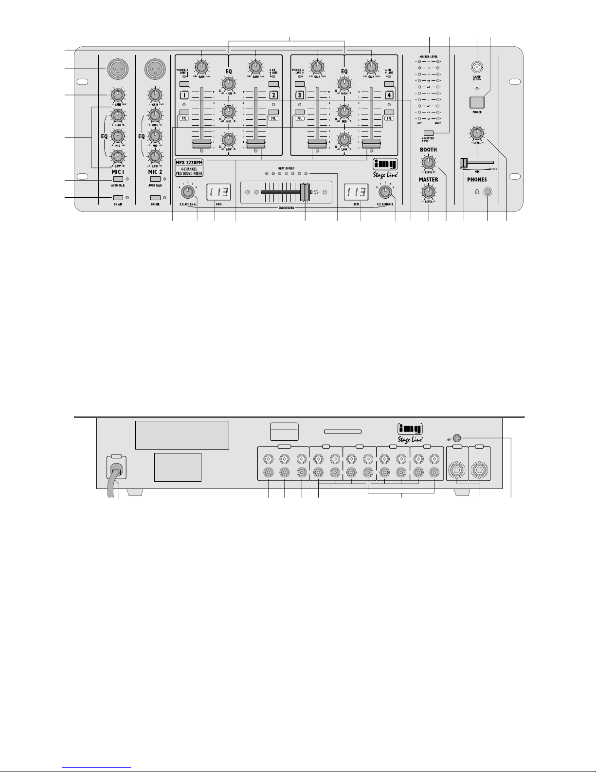
1.1 Frontseite
1 3fache Klangregelung (max. +15 dB/-30dB) je-
weils für die Kanalgruppe CH1 / CH 2 und die Kanalgruppe CH3/CH4:
HIGH = Höhen, MID = Mitten, LOW = Tiefen
2 Stereo-VU-Meter
3 Umschalttaste für das VU-Meter (2)
Taste nicht gedrückt „MASTER“:
VU-Meter zeigt den Masterpegel an
Taste gedrückt „PFL“:
VU-Meter zeigt entweder den Pre Fader-Pegel
des Eingangskanals, dessen Taste PFL (12)
gedrückt ist, an [Regler MIX (23) auf „PFL“] oder
das laufende Musikprogramm vor dem Masterregler (21) (Regler MIX auf „PROG.“)
4 BNC-Buchse LAMP zum Anschluss einer Pult-
leuchte (12V/5W max.)
5 Ein-/Ausschalter POWER mit Betriebsanzeige
6 Gain-Regler zum Einstellen der Eingangsverstär-
kung für die Kanäle CH1–CH4
7 Eingänge (XLR, sym.) zum Anschluss von Mono-
Mikrofonen an die beiden Mikrofonkanäle; parallel
geschaltet mit den Klinkenbuchsen (32) auf der
Geräterückseite
8 Pegelregler für die Mikrofonkanäle
9 3fache Klangregelung (max. ±15dB) für die Mikro-
fonkanäle:
HIGH = Höhen, MID = Mitten, LOW = Tiefen
10 Tasten AUTO TALK für die Talkover-Funktion:
Ist die Taste eines Mikrofonkanals gedrückt, werden bei Mikrofondurchsagen über diesen Kanal die
Pegel der Eingangskanäle CH1–CH4 automatisch um 15dB abgesenkt.
11 Tasten ON AIR zum Ein-/Ausschalten der Mikro-
fonkanäle
12 Tasten PFL zum Vorhören der Eingangskanäle
CH 1 – CH 4 vor den Kanalfadern (15) über einen
an der Buchse (24) angeschlossenen Kopfhörer
13 linker Zuordnungsschalter C.F. ASSIGN A; bestimmt,
welcher der Kanäle CH1–CH4 eingeblendet wird,
wenn der Crossfader (16) links steht
Für den ausgewählten Kanal werden die Taktschläge pro Minute (BPM) gemessen und auf dem
linken BPM-Display (14) angezeigt.
14 BPM-Display für den Kanal, der mit dem linken
Schalter C.F. ASSIGN A(13) ausgewählt wurde:
zeigt die Taktschläge pro Minute (BPM = beats per
minute) des gerade laufenden Musikstückes an
15 Pegelregler (Fader) für die Kanäle CH 1 – CH 4
16 Crossfader zum Überblenden zwischen zwei der
Kanäle CH 1 – CH 4; die jeweiligen Kanäle werden
mit den Schaltern C.F. ASSIGN (13 + 19) angewählt
17 LED-Anzeige BEAT OFFSET; dient als optische
Kontrolle bei der Synchronisation der Taktschläge
der beiden Musiktitel, zwischen denen übergeblendet werden soll:
Je weiter innen sich die jeweils leuchtende LED in
der LED-Kette befindet, desto mehr nähern sich
die Taktschläge der beiden Musiktitel an: leuchtet
die blaue LED in der Mitte, laufen die Titel synchron d.h. ihre Taktschläge liegen übereinander.
18 BPM-Display für den Kanal, der mit dem rechten
Schalter C.F. ASSIGN B (19) ausgewählt wurde:
zeigt die Taktschläge pro Minute (BPM = beats per
minute) des gerade laufenden Musikstückes an
19 rechter Zuordnungsschalter C.F. ASSIGN B; be-
stimmt, welcher der Kanäle CH1–CH4 eingeblendet wird, wenn der Crossfader (16) rechts steht
Für den ausgewählten Kanal werden die Taktschläge pro Minute (BPM) gemessen und auf dem
rechten BPM-Display (18) angezeigt.
20 Umschalttasten für die Eingänge der Kanäle
CH1–CH4
Taste nicht gedrückt:
Eingang PHONO (Kanal CH 1 und CH3) bzw.
Eingang CD (Kanal CH2 und CH4) ist angewählt
Taste gedrückt:
Eingang LINE des Kanals ist angewählt
21 Masterregler
D
A
CH
5
22 Pegelregler für den Monitorausgang BOOTH (28)
23 Regler MIX für den Kopfhörerausgang (24) und
das VU-Meter (2)
Position „PFL“ (Regler ganz links):
der Pre Fader-Pegel des Eingangskanals, dessen Taste PFL (12) gedrückt ist, wird über den
Kopfhörer abgehört und vom VU-Meter angezeigt
Position „PROG.“ (Regler ganz rechts):
das laufende Musikprogramm wird vor dem
Masterregler (21) abgehört und vom VU-Meter
angezeigt
Hinweis:
Das VU-Meter muss auf den Kopfhörerausgang
geschaltet sein [Umschalttaste (3) gedrückt].
24 6,3-mm-Klinkenbuchse zum Anschluss eines Ste-
reo-Kopfhörers (Impedanz ≥ 8Ω)
25 Pegelregler für den Kopfhörerausgang (24)
1.2 Rückseite
26 Netzkabel zum Anschluss des Gerätes an die
Stromversorgung (230V~/50Hz)
27 Stereo-Ausgang REC (Cinch-Buchsen) für den An-
schluss eines Tonaufnahmegerätes; der Aufnahmepegel ist unabhängig von der Stellung des
Masterreglers (21)
28 Stereo-Monitorausgang BOOTH (Cinch-Buchsen)
zum Anschluss einer Monitoranlage
29 Stereo-Ausgang MASTER (Cinch-Buchsen) für den
Anschluss des Verstärkers
30 Stereo-Eingänge LINE und CD (Cinch-Buchsen)
für die Kanäle CH1–CH4 zum Anschluss von
Geräten mit Line-Pegel-Ausgängen (z.B. MiniDiskRecorder, CD-Spieler, Kassettenrecorder)
31 Stereo-Eingänge PHONO (Cinch-Buchsen) für die
Kanäle CH1 und CH3 zum Anschluss von Plattenspielern mit Magnetsystem
32 Eingänge (6,3-mm-Klinkenbuchsen, sym.) zum An-
schluss von Mono-Mikrofonen an die beiden Mikrofonkanäle; parallel geschaltet mit den XLR-Buchsen (7) auf der Frontplatte
33 Anschluss GND für einen gemeinsamen Masse-
punkt, z.B. für die angeschlossenen Plattenspieler
2 Hinweise für den sicheren Gebrauch
Dieses Gerät entspricht der Richtlinie für elektromagnetische Verträglichkeit 89/ 336/ EWG und der Niederspannungsrichtlinie 73/23/EWG.
Beachten Sie auch unbedingt die folgenden Punkte:
●
Verwenden Sie das Gerät nur im Innenbereich.
Schützen Sie es vor Tropf- und Spritzwasser, hoher
Luftfeuchtigkeit und Hitze (zulässiger Einsatztemperaturbereich 0–40°C).
●
Stellen Sie keine mit Flüssigkeit gefüllten Gefäße,
z.B. Trinkgläser, auf das Gerät.
●
Nehmen Sie das Gerät nicht in Betrieb bzw. ziehen
Sie sofort den Netzstecker, wenn:
1. sichtbare Schäden am Gerät oder an der Netzanschlussleitung vorhanden sind,
2. nach einem Sturz oder Ähnlichem der Verdacht
auf einen Defekt besteht,
3. Funktionsstörungen auftreten.
Lassen Sie das Gerät in jedem Fall in einer Fachwerkstatt reparieren.
●
Eine beschädigte Netzanschlussleitung darf nur
durch den Hersteller oder durch eine autorisierte
Fachwerkstatt ersetzt werden.
●
Ziehen Sie den Netzstecker nie an der Zuleitung aus
der Steckdose, fassen Sie immer am Stecker an.
●
Verwenden Sie für die Reinigung nur ein trockenes,
weiches Tuch, niemals Wasser oder Chemikalien.
●
Wird das Gerät zweckentfremdet, falsch angeschlossen, nicht richtig bedient oder nicht fachgerecht repariert, kann keine Haftung für daraus
resultierende Sach- oder Personenschäden und
keine Garantie für das Gerät übernommen werden.
3 Einsatzmöglichkeiten
Das Mischpult MPX-222BPM mit vier Stereo-Kanälen,
zwei Mono-Mikrofonkanälen und integrierter Beatcounter-Funktion ist für beliebige DJ-Anwendungen im
privaten oder professionellen Bereich geeignet.
Das Gerät kann sowohl frei aufgestellt als auch in
ein Bedienpult eingebaut werden. Es eignet sich ebenso für die Montage in ein Rack (482mm /19"). Für die
Rackmontage wird eine Höhe von 4HE (1 Höheneinheit = 44,45 mm) benötigt.
4 Gerät anschließen
Vor dem Anschließen von Geräten bzw . vor dem Ändern
bestehender Anschlüsse das Mischpult ausschalten.
1) Die Stereo-Tonquellen an die entsprechenden
Cinch-Eingangsbuchsen der Kanäle CH1–CH4
anschließen (weiße Buchse L = linker Kanal; rote
Buchse R = rechter Kanal):
-
Geräte mit Line-Pegel-Ausgang (z. B. MiniDiskRecorder, CD-Spieler, Kassettenrecorder) an die
Buchsen CD und LINE (30);
-
Plattenspieler mit Magnetsystem an die Buchsen
PHONO (31).
Die Klemmschraube GND (33) kann als gemeinsamer Massepunkt genutzt werden: Den
Masseanschluss des Plattenspielers mit der
Klemmschraube verbinden.
Soll das Gerät endgültig aus dem Betrieb
genommen werden, übergeben Sie es zur
umweltgerechten Entsorgung einem örtlichen Recyclingbetrieb.
Achtung! Das Gerät wird mit lebensgefährlicher
Netzspannung (230V~) versorgt. Nehmen
Sie deshalb nie selbst Eingriffe am Gerät
vor. Durch unsachgemäßes Vorgehen besteht die Gefahr eines elektrischen Schlages. Außerdem erlischt beim Öffnen des
Gerätes jeglicher Garantieanspruch.

D
A
CH
6
2) Mono-Mikrofone an die XLR-Buchsen (7) auf der
Frontplatte oder an die Klinkenbuchsen (32) auf der
Geräterückseite anschließen.
3) Den Eingang des Verstärkers an den Masterausgang MASTER (29) anschließen.
4) Ist eine Monitoranlage vorhanden, den Verstärker
der Monitoranlage an den Ausgang BOOTH (28)
anschließen.
5) Sollen Tonaufnahmen gemacht werden, das Aufnahmegerät an den Record-Ausgang REC (27)
anschließen. Der Aufnahmepegel ist unabhängig
von der Stellung des Masterreglers (21).
6) Für eine optimale Pultbeleuchtung kann an die
BNC-Buchse LAMP (4) eine Schwanenhalsleuchte
(12 V/5 W max.) angeschlossen werden, z. B. die
Leuchte GNL-205 aus dem Programm von „img
Stage Line“. Die Leuchte wird mit dem Mischpult
ein- und ausgeschaltet.
7) Über einen Stereo-Kopfhörer kann sowohl der Pre
Fader-Pegel der Eingangskanäle CH 1 – CH4 sowie das laufende Musikprogramm vor dem Masterregler (21) abgehört werden (siehe Kap. 5.6). Den
Kopfhörer (Impedanz ≥ 8Ω) an die Buchse (24)
anschließen.
8) Zuletzt den Stecker des Netzkabels (26) in eine
Steckdose (230V~/50Hz) stecken.
5 Bedienung
Vor dem Einschalten sollten die Ausgangsregler MASTER (21) und BOOTH (22) auf Minimum gestellt werden, um starke Einschaltgeräusche zu vermeiden.
Dann das Mischpult mit dem Schalter POWER (5) einschalten. Zur Anzeige der Betriebsbereitschaft leuchtet die LED über dem Schalter. Anschließend die angeschlossenen Geräte anschalten.
5.1 Grundeinstellungen
5.1.1 Grundeinstellung der Kanäle CH1 – CH 4
Für eine optimale Pegeleinstellung der an den Eingangskanälen CH1–CH4 angeschlossenen Tonquellen alle Gain-Regler (6) und Klangregler (1) zunächst
in die Mittelposition drehen und die Schalter C.F.
ASSIGN (13 und 19) auf „x“ stellen (Überblendfunktion
ausgeschaltet).
1) Mit den Umschalttasten (20) die angeschlossenen
Signalquellen anwählen.
Taste nicht gedrückt:
Der Eingang PHONO (bei Kanal CH1 und CH3)
bzw. CD (bei Kanal CH2 und CH 4) ist angewählt.
Taste gedrückt – LED über der Taste leuchtet:
Der Eingang LINE des Kanals ist angewählt.
2) Mit dem Masterregler (21) wird der Gesamtpegel
aller angeschlossenen Tonquellen eingestellt. Den
Masterregler auf ca.
2
/3 des Maximums stellen, z. B.
auf Position 7.
3) Die Umschalttaste (3) darf nicht gedrückt sein: Bei
dieser Tastenstellung zeigt das VU-Meter (2) den
Stereo-Ausgangspegel an, der am Masterausgang
MASTER (29) zur Verfügung steht.
4) Zum Aussteuern eines Kanals die Fader (15) der
übrigen Kanäle auf Minimum stellen und die Tonsignale (Testsignale oder Musikstücke) auf den jeweiligen Eingangskanal geben.
5) Anhand des VU-Meters mit dem Fader den Pegel
des Kanals ausregeln. Optimale Aussteuerung liegt
vor, wenn bei den lautesten Passagen die 0-dBLEDs des VU-Meters aufleuchten. Übersteuerungen werden durch Aufleuchten der roten LEDs angezeigt.
Der Fader sollte nach der Pegeleinstellung auf
ca.
2
/3 des Maximums stehen, damit zum Ein- und
Ausblenden genügend Reglerweg vorhanden ist.
6) Bei sehr wenig oder sehr weit aufgezogenem Fader
muss der Pegel durch Regulierung der Eingangsverstärkung angepasst werden: Den GAIN-Regler (6)
des Kanals entsprechend zurück- bzw. aufdrehen
Die Eingangsverstärkung lässt sich durch Anzeige des Pre Fader-Pegels optimal einstellen. Dazu
das VU-Meter durch Drücken der Taste (3) in den
Anzeigemodus „PFL“ umschalten, den Regler MIX
(23) ganz nach links auf Position „PFL“ schieben
und die Taste PFL (12) des Kanals drücken: Das
VU-Meter zeigt dann den Signalpegel des Kanals
vor dem Kanalfader an.
7) Das VU-Meter durch Lösen der Taste (3) wieder in
den Anzeigemodus „MASTER“ schalten und mit
den Klangreglern (1) des Kanals – je eine 3fache
Klangreglung für die Kanalgruppe CH 1 / CH 2 und
die Kanalgruppe CH3/CH4 – das gewünschte
Klangbild einstellen: Mit den drei Reglern lassen
sich die Höhen (Regler HIGH), Mitten (Regler MID)
und Tiefen (Regler LOW) anheben (max. 15dB)
bzw. stark absenken (max. 30dB). Stehen die Regler in Mittelstellung, findet keine Frequenzgangbeeinflussung statt.
Hinweis: Klangeinstellungen wirken sich auf die
Pegel aus. Deshalb nach einer Klangregulierung
den Kanalpegel anhand der Pegelanzeige kontrollieren und ggf. korrigieren.
8) Die Pegel- und Klangeinstellung für die übrigen
belegten Eingangskanäle in der oben beschriebenen Weise durchführen.
5.1.2 Grundeinstellung der Mikrofonkanäle
Zum Einschalten eines Mikrofonkanals die Taste ON
AIR (11) des Kanals drücken. Zur Anzeige leuchtet die
LED neben der Taste. Die Fader (15) der Eingangskanäle CH 1 – CH 4 auf Minimum stellen und anhand
des VU-Meters (2) mit dem Regler GAIN (8) des
Kanals den optimalen Pegel einstellen. Mit den Klangreglern (9) – HIGH für die Höhen, MID für die Mitten,
Vorsicht! Stellen Sie die Lautstärke der Audioanlage
und die Kopfhörerlautstärke nie sehr hoch ein. Hohe
Lautstärken können auf Dauer das Gehör schädigen!
Das menschliche Ohr gewöhnt sich an große Lautstärken und empfindet sie nach einiger Zeit als nicht
mehr so hoch. Darum eine hohe Lautstärke nach der
Gewöhnung nicht weiter erhöhen.

D
A
CH
7
LOW für die Tiefen – das Klangbild für das Mikrofon
korrigieren (max. ±15 dB).
Die Pegel- und Klangeinstellungen für den zweiten
Mikrofonkanal in der gleichen Weise durchführen.
5.2 Überblendfunktion
1) Mit den zwei Zuordnungsschaltern C.F. ASSIGN
werden von den Eingangskanälen CH1–CH4 die
zwei Kanäle ausgewählt, zwischen denen übergeblendet werden soll:
Mit dem linken Schalter C.F. ASSIGN A (13) den
Kanal wählen, der eingeblendet werden soll, wenn
der Crossfader (16) nach links geschoben wird.
Mit dem rechten Schalter C.F. ASSIGN B (19) den
Kanal wählen, der eingeblendet werden soll, wenn
der Crossfader nach rechts geschoben wird.
2) Die Fader (15) der nicht benutzten Kanäle auf Minimum stellen und die beiden ausgewählten Kanäle
mit ihren Fadern optimal aussteuern (siehe Kapitel
5.1.1).
3) Mit dem Crossfader kann jetzt zwischen den beiden
gewählten Kanälen übergeblendet werden.
Sollen beide Kanäle gleichzeitig auf die Ausgänge gegeben werden, den Crossfader in die Mittelposition stellen.
4) Mit dem Masterregler (21) den gewünschten Gesamtpegel einstellen, der am Masterausgang (29)
zur Verfügung steht. Bei Übersteuerungen [rote
LEDs des VU-Meters (2) leuchten auf] den Masterpegel reduzieren.
5.3 Beatcounter
Die zwei Beatcounter des Mischpults messen für die
beiden Kanäle, die mit den Schaltern C.F. ASSIGN für
die Überblendfunktion ausgewählt wurden, die Taktschläge pro Minute (BPM = beats per minute). Die
gemessenen BPM werden über zwei Displays angezeigt.
Hinweis: Die Beatcounter werten ausschließlich BassBeats aus, die viermal hintereinander im etwa gleichen
Abstand auftreten (
4
/4-Takt). Musikstücke, die keine
klare Bass-Drum-Linie im
4
/4-Rhythmus aufweisen,
werden von den Beatcountern nicht erkannt und mit falschen Werten angezeigt.
5.3.1 BPM-Displays
Die meisten CD-Spieler für den Disco-Bereich verfügen über Bedienelemente zur Veränderung der Taktgeschwindigkeit (Pitch-Regler). Soll beim Überblenden zwischen den angeschlossenen Tonquellen (z. B.
zwei CD-Spieler) die Taktgeschwindigkeit des einen
Musikstückes über den Pitch-Regler an die Taktgeschwindigkeit des anderen anpasst werden, dienen
die beiden BPM-Displays des Mischpultes als optisches Hilfsmittel.
Das linke BPM-Display (14) zeigt die Beats für den
Kanal an, der mit dem linken Schalter C.F. ASSIGN A
(13) ausgewählt wurde und das rechte BPM-Display
(18) die Beats für den Kanal, der mit dem rechten
Schalter C.F. ASSIGN B (19) ausgewählt wurde. Läuft
auf dem gewählten Kanal kein Musikstück bzw. steht
der jeweilige ASSIGN-Schalter auf „x“, erscheint die
Anzeige [- - -] im Display.
Der Anzeigebereich liegt zwischen ca. 90BPM und
170BPM. Sind die BPM eines Titels niedriger, erscheint die Anzeige [- - -] oder ein falscher W ert im Display. Höhere BPM-Werte werden geteilt angezeigt
(z. B. Anzeige 90 BPM bei einem tatsächlichen Wert
von 180BPM).
5.3.2 Beat Offset-Anzeige
Um beim Überblenden einen fließenden Übergang zwischen den Titeln zu erreichen, müssen die Taktschläge
der beiden Titel synchronisiert werden, d.h. sie müssen
exakt aufeinander liegen. Über entsprechende Bedienelemente am CD-Spieler kann die Taktgeschwindigkeit
des eines Titels so angepasst werden, dass er synchron zum zweiten Titel läuft.
Bei der Synchronisation der Taktschläge der beiden
Musiktitel, zwischen denen übergeblendet werden soll,
dient die LED-Anzeige BEAT OFFSET (17) als optische Kontrolle. Je weiter außen die jeweils leuchtende
LED in der LED-Kette liegt, desto weniger synchron
laufen die beiden Musiktitel:
Leuchtet die blaue LED in der Mitte, laufen die Titel
synchron, d.h. ihre Taktschläge liegen übereinander.
Leuchtet eine der beiden daneben liegenden LEDs,
laufen die Titel fast synchron.
Leuchtet eine der vier äußeren LEDs, laufen die
Titel nicht synchron.
Hinweis: Liegen die BPM der beiden Titel weit auseinander, spricht die Beat Offset-Anzeige nicht an.
5.4 Mischen der Tonquellen
1) Zum Mischen der angeschlossenen Tonquellen die
Überblendfunktion ausschalten. Dazu die Schalter
C.F. ASSIGN (13 und 19) in die Position „x“ stellen.
2) Den Masterregler (21) so weit aufdrehen, dass das
Mischungsverhältnis der Tonquellen optimal einge-
stellt werden kann.
3) Mit den Pegelreglern der Eingangskanäle das ge-
wünschte Lautstärkeverhältnis der Tonquellen un-
tereinander einstellen. Wird ein Kanal nicht benutzt,
sollte sein Pegelregler auf Minimum gestellt werden.
4) Anhand des VU-Meters (2) mit dem Masterregler
den gewünschten Gesamtpegel einstellen, der am
Masterausgang (29) zur Verfügung steht.
Optimale Aussteuerung liegt vor, wenn bei den
lautesten Passagen der 0-dB-Bereich des VU-Meters aufleuchtet. Bei Übersteuerungen (rote LEDs
leuchten) den Ausgangspegel mit dem Masterregler
und/oder den Pegelreglern der Eingangskanäle
reduzieren.
5.5 Talkover-Funktion
Die Talkover-Funktion dient zur besseren Verständlichkeit von Mikrofondurchsagen bei laufendem Musikprogramm. Zum Aktivieren der Funktion für einen Mikrofonkanal die Taste AUTOTALK (10) des Kanals
drücken: Ist die Taste gedrückt (LED neben der Taste
leuchtet), werden bei Mikrofondurchsagen über diesen
Kanal die Pegel der Kanäle CH 1 – CH 4 automatisch

D
A
CH
8
um 15dB abgesenkt. Zum Abschalten der Funktion die
Taste wieder lösen.
5.6 Vorhören der Kanäle über einen Kopfhörer
Über die Vorhörfunktion (PFL = Pre Fader Listening)
ist es möglich, jeden der Eingangskanäle CH1–CH4
über einen an der Buchse (24) angeschlossenen
Kopfhörer abzuhören, auch wenn der dazugehörige
Kanalfader (15) auf Minimum steht. Dadurch kann z.B.
auf einer CD der gewünschte Titel ausgewählt oder
der richtige Zeitpunkt zum Einblenden einer Tonquelle
abgepasst werden.
Wahlweise ist es auch möglich, das laufende Mu-
sikprogramm vor dem Masterregler (21) abzuhören.
1) Zum Abhören eines Eingangskanals vor dem Kanalfader die Taste PFL (12) des Kanals drücken
(LED über der Taste leuchtet), und den Regler MIX
(23) ganz nach links schieben (Position „PFL“).
Zum Abhören des laufenden Musikprogramms
vor dem Masterregler den Regler MIX ganz nach
rechts schieben (Position „PROG.“).
2) Zum Umschalten des VU-Meters (2) auf den Kopfhörerausgang die Taste (3) drücken. Das VU-Meter
zeigt dann das Signal, das mit dem Regler MIX (23)
gewählt wurde.
3) Mit dem Pegelregler (25) die gewünschte Kopfhörerlautstärke einstellen.
5.7 Abhören des Musikprogramms über eine
Monitoranlage
Es besteht die Möglichkeit, das laufende Musikprogramm vor dem Masterregler (21) über eine an den
Buchsen BOOTH (28) angeschlossene Monitoranlage
abzuhören. Den Pegel für die Monitoranlage mit dem
Regler BOOTH (22) einstellen.
6 Technische Daten
Eingänge
Mic, mono: . . . . . . . . . . . 1,5 mV
Phono, stereo: . . . . . . . . 2,7mV
Line und CD, stereo: . . . 130 mV
Ausgänge
Master, stereo: . . . . . . . . 1V
Booth (Monitor), stereo: . 1V
Record, stereo:. . . . . . . . 0,5V
Kopfhörer, stereo:. . . . . . ≥ 8Ω
Allgemeine Daten
Frequenzbereich: . . . . . . 20–20000Hz
Klirrfaktor:. . . . . . . . . . . . 0,1%
Störabstand.. . . . . . . . . . > 53dB
Klangregelung CH1–CH4
Tiefen: . . . . . . . . . . . . +15dB,
-
30dB/50Hz
Mitten: . . . . . . . . . . . . +15dB,
-
30dB/1kHz
Höhen: . . . . . . . . . . . . +15 dB,
-
30dB/10kHz
Klangregelung Mic
Tiefen: . . . . . . . . . . . . ±15dB/50Hz
Mitten: . . . . . . . . . . . . ±15dB/1kHz
Höhen: . . . . . . . . . . . . ±15dB/10 kHz
Talkover (automatisch): . -15dB
Anschluss für Pultleuchte: 12 V/5 W max., BNC
Einsatztemperatur:. . . . . 0 – 40 °C
Stromversorgung:. . . . . . 230V~/50 Hz
Leistungsaufnahme:. . . . 10VA
Abmessungen : . . . . . . . 482 x 178 x 105 mm, 4 HE
Gewicht: . . . . . . . . . . . . . 3,8kg
Änderungen vorbehalten.
Diese Bedienungsanleitung ist urheberrechtlich für MONACOR®INTERNATIONAL GmbH & Co. KG geschützt.
Eine Reproduktion für eigene kommerzielle Zwecke – auch auszugsweise – ist untersagt.

Please unfold page 3. Then you can always see the
operating elements and connections described.
Contents
1 Operating Elements and Connections . . . . 9
1.1 Front side . . . . . . . . . . . . . . . . . . . . . . . . . . . . 9
1.2 Rear side . . . . . . . . . . . . . . . . . . . . . . . . . . . 10
2 Safety Notes . . . . . . . . . . . . . . . . . . . . . . . . 10
3 Applications . . . . . . . . . . . . . . . . . . . . . . . . 10
4 Connection of the Unit . . . . . . . . . . . . . . . . 10
5 Operation . . . . . . . . . . . . . . . . . . . . . . . . . . . 11
5.1 Basic settings . . . . . . . . . . . . . . . . . . . . . . . . 11
5.1.1 Basic setting of channels CH1 to CH4 . . . 11
5.1.2 Basic setting of the microphone channels . 11
5.2 Crossfading function . . . . . . . . . . . . . . . . . . . 12
5.3 Beat counter . . . . . . . . . . . . . . . . . . . . . . . . . 12
5.3.1 BPM displays . . . . . . . . . . . . . . . . . . . . . . . 12
5.3.2 Beat Offset display . . . . . . . . . . . . . . . . . . . 12
5.4 Mixing of the audio sources . . . . . . . . . . . . . 12
5.5 Talkover function . . . . . . . . . . . . . . . . . . . . . . 12
5.6 Pre fader listening of the channels
via headphones . . . . . . . . . . . . . . . . . . . . . . 13
5.7 Monitoring of the music programme
via a monitor system . . . . . . . . . . . . . . . . . . . 13
6 Specifications . . . . . . . . . . . . . . . . . . . . . . . 13
1 Operating Elements and Connections
1.1 Front side
1 3-way equalizer (max. +15 dB /-30 dB), each for
the channel group CH1/CH2 and the channel
group CH3 /CH 4: HIGH = high range, MID = midrange, LOW = bass range
2 Stereo VU meter
3 Selector button for the VU meter (2)
Button not pressed “MASTER”:
the VU meter shows the master level
Button pressed “PFL”:
the VU meter shows either the pre fader level of
the input channel, of which the PFL button (12) is
pressed [control MIX (23) set to “PFL”], or the
current music programme ahead of the master
control (21) (control MIX set to “PROG.”)
4 BNC jack LAMP for the connection of a console
lamp (12V/5W max.)
5 On/off POWER switch with operation indication
6 GAIN controls for adjusting the input amplification
for the channels CH1 to CH4
7 Inputs (XLR, bal.) for the connection of mono
microphones to the two microphone channels; connected in parallel to the 6.3mm jacks (32) on the
rear side of the unit
8 Level controls for the microphone channels
9 3-way equalizer (max. ±15 dB) for the microphone
channels: HIGH = high range, MID = midrange,
LOW = bass range
10 AUTO TALK buttons for the talkover function:
If the button of a microphone channel is pressed,
the levels of the input channels CH1 to CH4 are
automatically attenuated by 15dB in case of microphone announcements via this channel.
11 ON AIR buttons for switching on/off the micro-
phone channels
12 PFL buttons for pre fader listening of the input
channels CH 1 to CH 4 (15) via headphones connected to jack (24)
13 Left C.F. ASSIGN A switch; defines which of the
channels CH1 to CH4 is faded in if the crossfader
(16) is in the left position
For the selected channel the beats per minute
(BPM) are measured and shown on the left BPM
display (14).
14 BPM display for the channel selected with the left
C.F . ASSIGN Aswitch (13):
shows the beats per minute (BPM) of the music
piece currently playing
15 Level controls (faders) for channels CH 1 to CH 4
16 Crossfader for fading between two of the channels
CH1 to CH4; the respective channels are selected
with the C.F. ASSIGN switches (13 and 19)
17 LED indication BEAT OFFSET; serves as optical
control when synchronizing the beats of the two
music titles to be crossfaded
The further inside the corresponding LED lighting
up is located in the LED row, the more the beats
of the two music titles approach each other: if the
blue LED in the centre lights up, the titles are synchronized, i.e. their beats are exactly the same.
18 BPM display for the channel selected with the right
C.F. ASSIGN B switch (19):
shows the beats per minute (BPM) of the music
piece currently playing
19 Right C.F. ASSIGN B switch; defines which of the
channels CH1 to CH4 is faded in if the crossfader
(16) is in the right position
For the selected channel the beats per minute
(BPM) are measured and shown on the right BPM
display (18).
20 Selector buttons for the inputs of channels CH 1 to
CH4
button not pressed:
PHONO input (channels CH 1 and CH 3) or CD
input (channels CH2 and CH4) is selected
button pressed:
LINE input of the channel is selected
21 Master control
22 Level control for the monitor output BOOTH (28)
GB
9

GB
10
23 Control MIX for the headphone output (24) and
the VU meter (2)
“PFL” (control in the extreme left position):
the pre fader level of the input channel, of which
the PFL button (12) is pressed, is monitored via
headphones and displayed by the VU meter
“PROG.” (control in the extreme right position):
the current music programme is monitored ahead
of the master control (21) and displayed by the
VU meter
Note: The VU meter must be switched to the headphone output [selector button (3) pressed].
24 6.3 mm jack for the connection of stereo head-
phones (impedance ≥ 8Ω)
25 Level control for the headphone output (24)
1.2 Rear side
26 Mains cable for the connection of the unit to the
power supply (230V~/50Hz)
27 Stereo output REC (phono jacks) for the connec-
tion of an audio recording unit; the recording level is
independent of the position of the master control
(21)
28 Stereo monitor output BOOTH (phono jacks) for
the connection of a monitor system
29 Stereo output MASTER (phono jacks) for the
connection of the amplifier
30 Stereo inputs LINE and CD (phono jacks) for the
channels CH1 to CH4 for the connection of units
with line level outputs (e.g. minidisk recorder, CD
player, cassette recorder)
31 Stereo inputs PHONO (phono jacks) for the chan-
nels CH1 and CH3 for the connection of turntables
with magnetic system
32 Inputs (6.3 mm jacks, bal.) for the connection of
mono microphones to the two microphone channels; connected in parallel to the XLR jacks (7) on
the front plate
33 GND connection for a common grounding point,
e.g. for the connected turntables
2 Safety Notes
This unit corresponds to the directive for electromagnetic compatibility 89/336/ EEC and the low voltage
directive 73/23/EEC.
Also observe the following items in any case:
●
The unit is suitable for indoor use only. Protect it
against dripping water and splash water, high air
humidity, and heat (admissible ambient temperature
range 0–40°C).
●
Do not place any vessels filled with liquid, e.g. drinking glasses, on the unit.
●
Do not set the unit into operation and immediately
disconnect the mains plug from the mains socket if:
1. there is visible damage to the unit or mains cable,
2. a defect might have occurred after a drop or similar accident,
3. there are malfunctions.
The unit must in any case be repaired by authorized,
skilled personnel.
●
A damaged mains cable must only be replaced by
the manufacturer or authorized, skilled personnel.
●
Never pull the mains cable to disconnect the mains
plug from the mains socket, always seize the plug.
●
For cleaning only use a dry, soft cloth, by no means
chemicals or water.
●
If the unit is used for purposes other than originally
intended, if it is not correctly connected or operated,
or not repaired in an expert way, there is no liability
for resulting damage to persons or material and no
guarantee for the unit can be taken over.
●
Important for U.K. Customers!
The wires in this mains lead are coloured in accordance with the following code:
blue = neutral; brown = live
As the colours of the wires in the mains lead of this
appliance may not correspond with the coloured
markings identifying the terminals in your plug, proceed as follows:
1. The wire which is coloured blue must be connected to the terminal in the plug which is marked
with the letter N or coloured black.
2. The wire which is coloured brown must be
connected to the terminal which is marked with
the letter L or coloured red.
3 Applications
The mixer MPX-222BPM with four stereo channels,
two mono microphone channels, and integrated beat
counter function is suitable for any desired private or
professional DJ applications.
The unit can be placed as a table top unit as well as
be installed into a console. It is suitable for rack mounting (482mm/19") as well. For rack mounting a height of
4 rack spaces (1 rack space = 44.45mm) is necessary .
4 Connection of the Unit
Prior to the connection of units or changing of existing
connections, switch off the mixer.
1) Connect the stereo audio sources to the corre-
sponding phono input jacks of channels CH 1 to
CH4 (white jack L = left channel; red jack R = right
channel):
If the unit is to be put out of operation definitively, take it to a local recycling plant for
a disposal which is not harmful to the environment.
Attention! This unit uses dangerous mains voltage
(230 V~). To prevent a shock hazard, do
not open the cabinet. Leave servicing to
authorized skilled personnel only. Any
guarantee claim expires if the unit has been
opened.

-
units with line level output (e.g. mindisk recorder,
CD player, cassette recorder) to the jacks CD
and LINE (30);
-
turntables with magnetic system to the PHONO
jacks (31).
The clamping screw GND (33) can be used as
common grounding point: connect the grounding
connection of the turntable to the clamping
screw.
2) Connect mono microphones to the XLR jacks (7) on
the front plate or to the 6.3 mm jacks (32) on the
rear side of the unit.
3) Connect the input of the amplifier to the master output MASTER (29).
4) If a monitor system is present, connect the amplifier
of the monitor system to the BOOTH output (28).
5) For audio recordings, connect the recording unit to
the record output REC (27). The recording level is
independent of the position of the master control
(21).
6) For an optimum console illumination a gooseneck
lamp (12V/5W max.) can be connected to the BNC
jack LAMP (4), e.g. the lamp GNL-205 of the “img
Stage Line” range. The lamp is switched on and off
with the mixer.
7) Via stereo headphones the pre fader level of the
input channels CH1 to CH4 as well as the current
music programme ahead of the master control (21)
can be monitored (see chapter 5.6). Connect the
headphones (impedance ≥ 8Ω) to the jack (24).
8) Finally connect the plug of the mains cable (26) to a
mains socket (230V~/50Hz).
5 Operation
Prior to switching on, the output controls MASTER (21)
and BOOTH (22) should be set to minimum to avoid
strong inrush noise. Then switch on the mixer with the
POWER switch (5). The LED above the switch lights
up to indicate that the unit is ready for operation. Then
switch on the connected units.
5.1 Basic settings
5.1.1 Basic setting of channels CH1 to CH 4
For an optimum level adjustment of the audio sources
connected to the input channels CH1 to CH4, turn all
gain controls (6) and equalizer controls (1) to mid-position first, and set the C.F. ASSIGN switches (13 and
19) to “x” (crossfading function switched off).
1) Select the connected signal sources with the selector buttons (20).
Button not pressed:
the PHONO input (for channels CH1 and CH3)
or the CD input (for channels CH2 and CH4) is
selected.
Button pressed – LED above the button lights up:
the LINE input of the channel is selected.
2) With the master control (21) the total level of all
connected audio sources is adjusted. Set the master control to approx.
2
/3 of its maximum position,
e.g. to position 7.
3) The selector button (3) must not be pressed: with
this button position the VU meter (2) shows the
stereo output level which is present at the master
output MASTER (29).
4) To control a channel, set the faders (15) of the
remaining channels to minimum and feed the audio
signals (test signals or music pieces) to the respective input channel.
5) By means of the VU meter control the level of the
channel with the fader. The optimum level is obtained if the 0dB LEDs of the VU meter light up with
music peaks. In case of overload the red LEDs light
up.
After the level adjustment the fader should be
set to approx.
2
/3 of its maximum position so that
there is sufficient control range for fading in and out.
6) If the fader is slided up very much or only very little,
the level must be matched by adjusting the input
amplification: turn back or turn up the gain control
(6) of the channel correspondingly.
The input amplification can be adjusted in an
optimum way by the display of the pre fader level.
For this purpose press the button (3) to switch the
VU meter to the display mode “PFL”, slide the control MIX (23) to the left stop to position “PFL”, and
press the PFL button (12) of the channel: the VU
meter now shows the signal level of the channel
ahead of the channel fader.
7) Release button (3) to switch the VU meter to the
display mode “MASTER” again, and adjust the desired sound with the equalizer controls (1) of the
channel – a 3-way equalizer each for the channel
group CH1/CH2 and the channel group CH3/CH4:
with the three controls the high range (HIGH controls), the midrange (MID controls), and the bass
range (LOW controls) can be boosted (max. 15dB)
or attenuated to a large extent (max. 30dB). If the
controls are in mid-position, there is no influence on
the frequency response.
Note: Sound adjustments influence the levels.
Therefore, after a sound adjustment, check the
channel level by means of the level display and correct it, if necessary.
8) Make the level and sound adjustments for the remaining connected input channels as described
above.
5.1.2 Basic setting of the microphone channels
To switch on a microphone channel, press the ON AIR
button (11) of the channel. The LED next to the button
lights up as indication. Set the faders (15) of the input
Caution! Never adjust the audio system or the headphones to a very high volume. Permanent high volumes may damage your hearing! The human ear will
get accustomed to high volumes which do not seem
to be that high after some time. Therefore, do not further increase a high volume after getting used to it.
GB
11

GB
12
channels CH 1 to CH 4 to minimum, and adjust the
optimal level with the GAIN control (8) of the channel
by means of the VU meter (2). Correct the sound for
the microphone (max. ±15 dB) with the equalizer controls (9) – HIGH for the high range, MID for the midrange, LOW for the bass range.
Make the level and sound adjustments for the
second microphone channel in the same way.
5.2 Crossfading function
1) With the two C.F. ASSIGN switches select the two
channels of the input channels CH 1 – CH 4 to be
crossfaded:
With the left C.F. ASSIGN A switch (13) select the
channel to be faded in if the crossfader (16) is slid
to the left.
With the right C.F. ASSIGN B switch (19) select the
channel to be faded in if the crossfader is slid to the
right.
2) Set the faders (15) of the channels not used to minimum and control the two selected channels with
their faders in an optimum way (see chapter 5.1.1).
3) With the crossfader, it is now possible to fade between the two selected channels.
If both channels are to be fed to the outputs at the
same time, set the crossfader to the mid-position.
4) With the master control (21) adjust the desired total
level which is available at the master output (29). In
case of overload [red LEDs of the VU meter (2) light
up] reduce the master level.
5.3 Beat counter
The two beat counters of the mixer measure the beats
per minute (BPM) for the two channels selected with
the C.F. ASSIGN switches for the crossfading function.
The measured BPM are shown via two displays.
Note: the beat counters only evalute bass beats which
occur four times in succession at approx. the same
distance (
4
/4 beat). Music pieces which do not show
any clear bass drum line in the
4
/4 rhythm are not recognized by the beat counters and displayed with wrong
values.
5.3.1 BPM displays
Most CD players for disco applications are provided
with operating elements to change the speed of the
beat (pitch controls). For matching the pitch of one
music piece to that of the other via the pitch control
when crossfading between the connected audio sources (e.g. two CD players), the two BPM displays of the
mixer serve as optical aid.
The left BPM display (14) shows the beats for the
channel selected with the left C.F. ASSIGN A switch
(13) and the right BPM display (18) the beats for the
channel selected with the right C.F. ASSIGN B switch
(19). If no music piece is playing on the selected channel or if the respective ASSIGN switch is set to “x”, the
display is [- - -].
The display range is between approx. 90 BPM and
170 BPM. If the BPM of a title are lower, the display is
[- - -] or a wrong value. Higher BPM values are displayed in a divided way (e.g. display 90 BPM in case
of an actual value of 180 BPM).
5.3.2 Beat Offset display
To obtain a smooth transition between the titles when
crossfading, the beats of both titles have to be synchronized, i.e. they must be exactly the same. Via corresponding operating elements on the CD player the
pitch of one title can be matched so that it is synchronized with the second title.
When synchronizing the beats of the two music
titles to be crossfaded, the LED indication BEAT OFFSET (17) serves as optical control. The further outside
the corresponding LED lighting up is located in the LED
row, the less the two music titles are synchronized:
If the blue LED in the centre lights up, the titles are
synchronized, i.e. their beats are exactly the same.
If one of the two LEDs next to it lights up, the titles
are almost synchronized.
If one of the four outer LEDs lights up, the titles are
not synchronized.
Note: If the BPM of the two titles are far away from
each other, the beat offset display does not respond.
5.4 Mixing of the audio sources
1) To mix the connected audio sources, switch off the
crossfading function. For this purpose, set the C.F.
ASSIGN switches (13 and 19) to position “x”.
2) Turn up the master control (21) so much that the
mixing relation of the audio sources can be ad-
justed in an optimum way.
3) With the level controls of the input channels adjust
the desired volume relation of the audio sources
with each other. If a channel is not used, its level
control should be set to minimum.
4) By means of the VU meter (2) adjust with the mas-
ter control the desired total level which is available
at the master output (29).
The optimum level is obtained if the 0dB range
of the VU meter lights up with music peaks. In case
of overload (red LEDs light up), reduce the output
level with the master control and / or the level controls of the input channels.
5.5 Talkover function
The talkover function serves for better intelligibility
of microphone announcements during the music programme. To activate the funcion for a microphone
channel, press the AUTO TALK button (10) of the
channel: if the button is pressed (LED next to the button lights up), the levels of the channels CH1 to CH4
are automatically attenuated by 15 dB during microphone announcements. To switch off the function, release the button again.

5.6 Pre fader listening (PFL) of the channels via
headphones
Via the pre fader listening function each of the input
channels CH 1 to CH 4 can be monitored via headphones connected to the jack (24), even if the
corresponding channel fader (15) is set to minimum.
Thus, e.g. the desired title on a CD can be selected or
the right moment for fading in an audio source can be
timed.
Alternatively it is also possible to monitor the music
programme currently playing ahead of the master control (21).
1) To monitor an input channel ahead of the channel
fader, press the PFL button (12) of the channel
(LED above the button lights up) and slide the con-
trol MIX (23) to the extreme left position (“PFL”).
To monitor the current music programme ahead
of the master control, slide the control MIX to the
extreme right position (“PROG.”).
2) To switch the VU meter (2) to the headphone output, press the button (3). Then the VU meter shows
the signal selected with the control MIX (23).
3) With the level control (25) adjust the desired headphone volume.
5.7 Monitoring of the music programme via a
monitor system
The music programme currently playing can be monitored ahead of the master control (21) via a monitor
system connected to the BOOTH jacks (28). Adjust the
level for the monitor system with the BOOTH control
(22).
6 Specifications
Inputs
Mic, mono: . . . . . . . . . . . 1.5 mV
Phono, stereo: . . . . . . . . 2.7mV
Line and CD, stereo: . . . 130 mV
Outputs
Master, stereo: . . . . . . . . 1 V
Booth (monitor), stereo: . 1V
Record, stereo:. . . . . . . . 0.5V
Headphones, stereo: . . . ≥ 8 Ω
General information
Frequency range:. . . . . . 20 – 20 000 Hz
THD:. . . . . . . . . . . . . . . . 0.1%
S/N ratio: . . . . . . . . . . . . > 53dB
Equalizer CH1 to CH4
bass:. . . . . . . . . . . . . . +15dB,
-
30dB/50Hz
mid: . . . . . . . . . . . . . . +15dB,
-
30dB/1kHz
high: . . . . . . . . . . . . . . +15 dB,
-
30dB/10kHz
Equalizer Mic
bass:. . . . . . . . . . . . . . ±15 dB/50 Hz
mid: . . . . . . . . . . . . . . ±15dB/1kHz
high: . . . . . . . . . . . . . . ±15dB/10 kHz
Talkover (automatic): . . .
-
15dB
Connection for
console lamp:. . . . . . . . . 12 V/5 W max., BNC
Ambient temperature:. . . 0–40°C
Power supply:. . . . . . . . . 230V~/50 Hz
Comsumption: . . . . . . . . 10VA
Dimensions: . . . . . . . . . . 482 x 178 x 105mm,
4 rack spaces
Weight:. . . . . . . . . . . . . . 3.8 kg
Subject to change.
GB
13
All rights reserved by MONACOR ®INTERNATIONAL GmbH & Co. KG. No part of this instruction manual may
be reproduced in any form or by any means for any commercial use.

Ouvrez le présent livret page 3 de manière à visualiser les éléments et branchements.
Table des matières
1 Eléments et branchements . . . . . . . . . . . . 14
1.1 Face avant . . . . . . . . . . . . . . . . . . . . . . . . . . 14
1.2 Face arrière . . . . . . . . . . . . . . . . . . . . . . . . . 15
2 Conseils d’utilisation . . . . . . . . . . . . . . . . . 15
3 Possibilités d’utilisation . . . . . . . . . . . . . . 15
4 Branchements . . . . . . . . . . . . . . . . . . . . . . . 15
5 Fonctionnement . . . . . . . . . . . . . . . . . . . . . 16
5.1 Réglages de base . . . . . . . . . . . . . . . . . . . . . 16
5.1.1 Réglage de base des canaux CH1–CH4 16
5.1.2 Réglage de base des canaux micro . . . . . . 16
5.2 Fondu-enchaîné . . . . . . . . . . . . . . . . . . . . . . 16
5.3 Compteur de beats . . . . . . . . . . . . . . . . . . . . 17
5.3.1 Affichage BPM . . . . . . . . . . . . . . . . . . . . . . 17
5.3.2 Affichage Beat Offset . . . . . . . . . . . . . . . . . 17
5.4 Mixage des sources . . . . . . . . . . . . . . . . . . . 17
5.5 Fonction Talkover . . . . . . . . . . . . . . . . . . . . . 17
5.6 Préécoute des canaux via un casque . . . . . . 17
5.7 Préécoute du programme musical
via un système Monitor . . . . . . . . . . . . . . . . . 18
6 Caractéristiques techniques . . . . . . . . . . . 18
1 Eléments et branchements
1.1 Face avant
1 Egaliseur 3 voies (+15 dB/-30 dB max.) respec-
tivement pour le groupe CH 1/CH 2 et le groupe
CH3/CH4 :
HIGH : aigus, MID : médiums, LOW : graves
2 VU-mètre stéréo
3 Commutateur pour le VU-mètre (2) :
touche non enfoncée “MASTER” :
le VU-mètre indique le niveau Master
touche enfoncée “PFL” :
indique soit le niveau pré fader du canal d’entrée
dont la touche PFL (12) est enfoncée [potentiomètre MIX (23) sur “PFL”] soit le programme
musical en cours avant le réglage Master (21)
[potentiomètre MIX (23) sur “PROG.”]
4 Prise BNC LAMP pour brancher une lampe col de
cygne 12V/5W max.
5 Interrupteur POWER Marche/Arrêt avec témoin de
fonctionnement
6 Potentiomètres de réglage de gain : réglage de
l’amplification d’entrée pour les canaux CH1–CH4
7 Entrées (XLR symétriques) pour brancher des
micros mono aux 2 canaux micro ; branchées en
parallèle avec les prises Jack 6,35 (32) de la face
arrière
8 Potentiomètres de réglages de niveau pour les
canaux micro
9 Egaliseur 3 voies (±15 dB max) pour les canaux
micro : HIGH : aigus, MID : médiums, LOW : graves
10 Touches AUTO TALK pour la fonction Talkover :
Si la touche d’un canal micro est enfoncée, les niveaux des canaux d’entrée CH1–CH4 sont automatiquement diminués de 15 dB lors d’annonces
micro.
11 Touches ON AIR : marche/arrêt des canaux micro
12 Touches PFL : préécoute des canaux d’entrée
CH1–CH4 avant les faders des canaux (15), via
un casque relié à la prise (24)
13 Commutateur d’attribution C.F. ASSIGN Agauche :
détermine quel canal CH1–CH4 est utilisé pour le
fondu-enchaîné lorsque le potentiomètre de fonduenchaîné (16) est à gauche
Pour le canal sélectionné, le nombre de beats par
minute (BPM) est mesuré et affiché sur l’affichage
gauche BPM (14).
14 Affichage BPM pour le canal sélectionné avec le
commutateur C.F. ASSIGN A(13) gauche :
indique le nombre de beats par minute (BPM) pour
le morceau en cours
15 Potentiomètres de réglage de niveau (faders) pour
les canaux CH1–CH4
16 Potentiomètre pour effectuer un fondu-enchaîné
entre deux des canaux CH 1 – CH 4 ; les canaux
sont sélectionnés avec les commutateurs C.F.
ASSIGN (13 et 19)
17 LEDs BEAT OFFSET : servent de contrôle optique
lors de la synchronisation des beats des 2 titres
entre lesquels le fondu-enchaîné est effectué
Plus la LED correspondante qui brille est vers
l’intérieur de la chaîne des LEDs, plus les rythmes des deux titres de musique sont proches ; si
la LED bleue au milieu brille, les titres défilent de
manière synchrone, c’est-à-dire que leurs rythmes coïncident.
18 Affichage BPM pour le canal sélectionné avec le
commutateur C.F. ASSIGN B (19) droit :
indique le nombre de beats par minute (BPM) du
morceau en cours
19 Commutateur d’attribution C.F. ASSIGN B droit :
détermine quel canal CH1–CH4 est utilisé pour le
fondu-enchaîné lorsque le potentiomètre de fonduenchaîné (16) est à droite
Pour le canal sélectionné, le nombre de beats par
minute (BPM) est mesuré et affiché sur l’affichage
droit BPM (18).
20 Commutateurs pour les entrées des canaux
CH1–CH4
touche non enfoncée :
entrée PHONO (canal CH 1 et CH 3) ou entrée
CD (canal CH2 et CH4) sélectionnée
F
B
CH
14

touche enfoncée :
entrée LINE du canal sélectionnée
21 Réglage Master
22 Réglage de niveau pour la sortie Monitor BOOTH
(28)
23 Potentiomètre MIX pour la sortie casque (24) et
le VU-mètre (2)
Position “PFL” (potentiomètre à gauche) :
le niveau pré fader du canal d’entrée dont la touche PFL (12) est enfoncée, est écouté dans le
casque et affiché par le VU-mètre
Position “PROG.” (potentiomètre à droite) :
le programme musical en cours est écouté avant
le réglage Master (12) et affiché par le VU-mètre
Conseil : le VU-mètre doit être commuté sur la sortie casque [touche (3) enfoncée].
24 Prise Jack 6,35 pour brancher un casque stéréo
(impédance ≥ 8Ω)
25 Potentiomètre de réglage de niveau pour la sortie
casque (24)
1.2 Face arrière
26 Cordon secteur d’alimentation 230 V~/50Hz
27 Sortie stéréo REC (prises RCA) pour brancher un
enregistreur ; le niveau d’enregistrement est indépendant de la position du réglage Master (21)
28 Sortie Monitor stéréo BOOTH (prises RCA) pour
brancher un système monitor
29 Sortie MASTER (prises RCA) pour brancher l’am-
plificateur
30 Entrées stéréo LINE et CD (prises RCA) pour les
canaux CH1–CH4 pour brancher des appareils à
sorties niveau Ligne (enregistreur de mini-disques,
lecteur CD, platine-cassette etc.)
31 Entrées stéréo PHONO (prises RCA) pour les
canaux CH 1 et CH3 pour brancher des platine
diques à système magnétique
32 Entrées (prises Jack 6,35 symétriques) pour bran-
cher des micros mono aux deux canaux micro ;
branchées en parallèle aux prises XLR (7) de la
face avant
33 Branchement GND pour un point de masse com-
mun, par exemple pour les platine disques reliées
2 Conseils d’utilisation
La MPX-222BPM répond à la norme européenne
89 / 336/CEE relative à la compatibilité électromagnétique et à la norme 73/23/CEE portant sur les appareils à basse tension.
Respectez scrupuleusement les points suivants :
●
L’appareil n’est conçu que pour une utilisation en
intérieur. Protégez-le des éclaboussures, de tout
type de projections d’eau, de l’humidité et de la chaleur (température ambiante admissible 0–40°C).
●
En aucun cas, vous ne devez poser d’objet contenant du liquide ou un verre sur l’appareil.
●
Ne faites pas fonctionner l’appareil ou débranchez immédiatement la prise du cordon du secteur lorsque :
1. des dommages sur l’appareil apparaissent.
2. après une chute ou un cas similaire, vous avez un
doute sur l’état de l’appareil.
3. des défaillances apparaissent.
Dans tous les cas, les dommages doivent être réparés par un technicien spécialisé.
●
Tout cordon secteur endommagé doit être remplacé
par le fabricant ou un technicien habilité.
●
Ne débranchez jamais l’appareil en tirant sur le cordon secteur, tenez-le toujours par la prise.
●
Pour nettoyer l’appareil, utilisez uniquement un chiffon sec et doux, en aucun cas, de produits chimiques ou d’eau.
●
Nous déclinons toute responsabilité en cas de dommages corporels ou matériels résultants si l’appareil
est utilisé dans un but autre que celui pour lequel il a
été conçu, s’il n’est pas correctement branché, utilisé ou n’est pas réparé par une personne habilitée,
de même, la garantie deviendrait caduque.
3 Possibilités d’utilisation
La table de mixage MPX-222BPM est équipée de quatre canaux stéréo, deux canaux micro mono et d’une
fonction compteur de beats ; elle est particulièrement
bien adaptée à des utilisations DJ privées ou professionnelles.
L’appareil peut être placé directement sur une table
ou dans un pupitre. Il est également possible de le monter dans un rack au standard 482mm(19"), 4 unités de
hauteur (1 unité = 44,45mm) sont alors nécessaires.
4 Branchements
Avant d’effectuer tout branchement ou de les modifier,
éteignez la table.
1) Reliez les sources stéréo aux prises d’entrée RCA
correspondantes des canaux CH1–CH4 (prise
blanche L = canal gauche, prise rouge R = canal
droit) :
-
appareils à sortie niveau Ligne (par exemple, lecteur CD, enregistreur de mini-disques, platinecassette) aux prises CD ou LINE (30) ;
-
platine disques à système magnétique aux prises
PHONO (31). La borne GND (33) peut être utilisée
comme point de masse commun : reliez le branchement masse de la platine disques à la borne.
Lorsque l’appareil est définitivement retiré
du service, vous devez le déposer dans
une usine de recyclage adaptée pour contribuer à son élimination non polluante.
Attention ! La table de mixage est alimentée par une
tension dangereuse en 230 V~. Ne touchez jamais l'intérieur de l'appareil, car
en cas de mauvaise manipulation vous
pourriez subir une décharge électrique
mortelle. En outre, l’ouverture de l’appareil rend tout droit à la garantie caduque.
F
B
CH
15

2) Reliez les micros mono aux prises XLR (7) de la
face avant ou aux prises Jack (32) de la face
arrière.
3) Reliez l’entrée de l’amplificateur à la sortie Master
MASTER (29).
4) Si un système Monitor est prévu, reliez l’amplificateur du système à la sortie BOOTH (28).
5) Si des enregistrements doivent être effectués, connectez l’enregistreur à la sortie REC (27) ; le niveau
d’enregistrement est indépendant de la position du
réglage Master (21).
6) Vous pouvez brancher une lampe col de cygne à la
prise BNC LAMP (4) (12V/ 5W max.) par exemple
la modèle GNL-205 de la gamme “img Stage Line”.
La lampe est allumée/éteinte avec la table.
7) Via un casque stéréo, vous pouvez effectuer une
préécoute du niveau pré fader des canaux d’entrée
CH1–CH 4 et du programme musical en cours avant
le réglage Master (21) (voir chapitre 5.6). Reliez le
casque (impédance ≥ 8Ω) à la prise (24).
8) Reliez maintenant le cordon secteur (26) à une
prise 230V~/50Hz.
5 Fonctionnement
Avant d’allumer la table, mettez les réglages MASTER
(21) et BOOTH (22) sur le minimum de manière à éviter tout bruit fort lors de l’allumage. Allumez ensuite la
table avec l’interrupteur POWER (5) ; la LED au-dessus de l’interrupteur sert de témoin de fonctionnement.
Allumez ensuite les autres appareils.
5.1 Réglages de base
5.1.1 Réglage de base des canaux CH1 – CH 4
Pour un réglage optimal des niveaux des sources
reliées aux canaux CH 1– CH 4, mettez d’abord les
réglages de Gain (6) et de l’égaliseur (1) sur la position
médiane et mettez les commutateurs C.F. ASSIGN
(13 et 19) sur “x” (fonction fondu-enchaîné déconnectée).
1) Avec les touches (20), sélectionnez les sources
branchées :
touche non enfoncée :
l’entrée PHONO (canal CH1 et CH3) ou CD
(canal CH2 et CH4) est sélectionnée.
touche enfoncée – la LED au-dessus de la touche
brille :
l’entrée LINE du canal est sélectionnée.
2) Réglez le niveau général de l’ensemble des sources reliées avec le réglage Master (21). Mettez-le à
2
/3 environ du maximum, soit sur la position 7.
3) La touche (3) ne doit pas être enfoncée ; le VUmètre (2) indique alors le niveau de sortie stéréo
disponible à la sortie Master MASTER (29).
4) Pour régler un canal, mettez les faders (15) des
autres canaux sur le minimum et appliquez les signaux (signaux de test ou morceaux de musique)
sur le canal d’entrée choisi.
5) Selon les indications du VU-mètre, réglez le niveau
du canal avec le fader. Le réglage est optimal lorsque, pour des passages les plus élevés, les LEDs
0dB du VU-mètre brillent. Toute surcharge est indiquée par l’allumage des LEDs rouges.
Une fois le réglage effectué, le potentiomètre de-
vrait être à
2
/3 environ du maximum de manière à
avoir assez de place pour effectuer le fondu-enchaîné.
6) Si le fader n’est pas assez poussé, ou s’il est trop
poussé, le niveau doit être adapté en adaptant l’amplification d’entrée : selon le cas, tournez le réglage
de gain (6) du canal à droite ou à gauche.
L’amplification d’entrée est réglable de manière
optimale grâce à l’affichage du niveau pré fader.
Commutez le VU-mètre sur “PFL” en enfonçant la
touche (3), mettez le potentiomètre MIX (23) entièrement à gauche sur la position “PFL”, enfoncez
la touche PFL (12) du canal : le VU-mètre indique
alors le niveau du canal avant le fader.
7) Relâchez la touche (3) pour commuter le VU-mètre
sur “MASTER”. A vec les réglages de tonalité (1) du
canal – un égaliseur 3 voies respectivement pour le
groupe de canaux CH 1 / CH2 et le groupe de canaux CH3 / CH 4 – vous pouvez régler l’image sonore : vous pouvez augmenter les graves (LOW),
médiums (MID) aigus (HIGH) de 15dB max. ou les
diminuer de 30dB max. En position médiane, il n’y
a pas de modification de tonalité.
Remarque : les réglages de tonalité modifient les
niveaux ; une fois le réglage de tonalité effectué,
vérifiez le niveau du canal à l’aide du VU-mètre et le
cas échéant, effectuez les corrections nécessaires.
8) Effectuez les réglages décrits précédemment pour
les autres canaux.
5.1.2 Réglage de base des canaux micro
Pour allumer un canal micro, enfoncez la touche ON
AIR (11) du canal. La LED à côté de la touche brille :
mettez les potentiomètres (15) des canaux d’entrée
CH1–CH4 sur le minimum et, selon les indications du
VU-mètre (2), réglez le niveau avec le réglage GAIN (8)
de manière optimale. Corrigez l’image sonore (±15 dB
max.) avec l’égaliseur (9) : HIGH (aigus), MIDI (médiums) et LOW (graves).
Effectuez les réglages pour le second canal micro
de la même manière.
5.2 Fondu-enchaîné
1) Avec les deux commutateurs C.F. ASSIGN, sélectionnez des canaux d’entrée CH1–CH4 les 2 canaux utilisés pour le fondu-enchaîné :
avec le commutateur gauche C.F. ASSIGN A
(13), sélectionnez le canal utilisé lorsque le potentiomètre de fondu-enchaîné (16) est à gauche ;
Attention : Ne réglez pas le volume de l’installation
audio et du casque trop fort. Un volume trop élevé
peut, à long terme, générer des troubles de l’audition.
L’oreille humaine s’habitue à des volumes élevés et
ne les perçoit plus comme tels au bout d’un certain
temps. Nous vous conseillons donc de régler le
volume et de ne plus le modifier.
F
B
CH
16

avec le commutateur droit C.F. ASSIGN B (19),
sélectionnez le canal utilisé lorsque le potentiomètre de fondu-enchaîné (16) est à droite.
2) Mettez les faders (15) des canaux non utilisés sur le
minimum et réglez le niveau optimal pour les canaux sélectionnés avec leurs faders (voir chapitre
5.1.1).
3) Avec le potentiomètre de fondu-enchaîné, vous
pouvez maintenant effectuer votre manipulation.
Si les deux canaux doivent se trouver simultanément sur les sorties, mettez le potentiomètre en
position médiane.
4) Avec le réglage Master (21), réglez le niveau général souhaité, se trouvant sur la sortie Master (29).
En cas de surcharges [LEDs rouges du VU-mètre
(2) allumées], diminuez le niveau Master.
5.3 Compteur de beats
Les deux compteurs de beats de la table mesurent pour
les deux canaux sélectionnés pour le fondu-enchaîné
avec les commutateurs C.F. ASSIGN, le nombre de
beats par minutes (BPM) ; les BPM mesurés sont visibles sur deux affichages.
Remarque : les compteurs de beats ne comptent que
les beats graves qui apparaissent les uns à la suite
des autres dans un intervalle quasi identique (rythme
4
/4). Les morceaux qui ne présentent pas de ligne bass
drum au rythme
4
/4 claire, ne sont pas reconnus par
les compteurs ; les indications affichées sont erronées.
5.3.1 Affichages BPM
La majorité des lecteurs CD prévus pour une utilisation
disco dispose d’éléments permettant de modifier la vitesse (réglages Pitch). Si pour un fondu-enchaîné entre les sources reliées (par exemple deux lecteurs CD),
la vitesse d’un morceau doit être adaptée à la vitesse
d’un autre morceau via le réglage pitch, utilisez les
2 affichages BPM de la table comme contrôle visuel.
L’af fichage BPM gauche (14) indique les beats pour
le canal sélectionné avec le commutateur C.F.
ASSIGN A (13) gauche, l’affichage BPM droit (18) le
nombre de beats pour le canal sélectionné avec le
commutateur C.F. ASSIGN B (19) droit. Si sur le canal
sélectionné, il n’y a pas de morceau de musique ou si
le commutateur ASSIGN correspondant est sur “x”,
l’affichage indique [- - -].
La plage d’affichage va de 90 BPM environ à
170 BPM. Si les BPM d’un titre sont inférieurs à cette
valeur, [- - -] s’affiche, ou bien la valeur indiquée est
fausse. Pour des valeurs plus élevées, l’affichage indique des valeurs tronquées (par exemple valeur réelle
180 BPM, valeur affichée 90 BPM).
5.3.2 Affichage Beat Offset
Lors d’un fondu-enchaîné, pour obtenir une certaine
fluidité entre les titres, les rythmes des deux morceaux
doivent être synchronisés ; certaines fonctions des lecteurs CD permettent d’adapter la vitesse d’un titre pour
qu’il soit synchronisé avec l’autre titre.
Lors de la synchronisation des rythmes des deux
morceaux de musique, entre lesquels le fondu-enchaîné est effectué, les LEDs BEAT OFFSET (17) servent
de témoin visuel. Plus la LED correspondante qui brille
est vers l’extérieur de la chaîne des LEDs, moins les
deux titres de musique défilent de manière synchrone :
Si la LED bleue au milieu brille, les titres défilent de
manière synchrone, c’est-à-dire que leurs rythmes
coïncident.
Si une des deux LEDs à côté brille, les titres sont
quasiment synchrones.
Si une des quatre LEDs extérieures brille, les titres
ne défilent pas de manière synchrone.
Remarque : si les BPM des deux titres sont trop éloignés, l’affichage Beat Offset ne correspond pas.
5.4 Mixage des sources
1) Pour mixer les sources reliées, déconnectez la
fonction fondu-enchaîné. Pour faire cela, mettez les
commutateurs C.F. ASSIGN (13 et 19) sur la posi-
tion “x”.
2) Tournez le réglage Master (21) jusqu’a une position
qui permet de régler le rapport de mixage des sour-
ces d’une manière optimale.
3) Avec les réglages de niveau des canaux d’entrée,
réglez le rapport de volume des sources entre elles ;
si un canal n’est pas utilisé, mettez son potentio-
mètre au minimum.
4) En fonction des indications du VU-mètre (2), réglez
avec le potentiomètre Master le niveau général dis-
ponible à la sortie Master (29).
Le réglage est optimal lorsque pour des passages les plus élevés, la plage 0 dB du VU-mètre brille
brièvement. En cas de surcharge (LEDs rouges allumées), diminuez le niveau de sortie avec le réglage
Master et /ou les réglages de niveau des canaux
d’entrée.
5.5 Fonction Talkover
La fonction TALKOVER permet une meilleur compréhension des annonces micro pendant la diffusion de
morceaux de musique. Pour activer cette fonction, enfoncez la touche AUT O T ALK (10) du canal concerné :
si la touche est enfoncée, la LED à côté de la touche
brille, les niveaux des canaux CH1–CH4 sont automatiquement diminués de 15 dB pendant les annonces via ce canal. Enfoncez une nouvelle fois la touche
pour déconnecter la fonction.
5.6 Préécoute des canaux via un casque
La fonction préécoute PFL (PFL = pre fader listening)
permet d’écouter dans un casque relié à la prise
(24) un des canaux CH1–CH4 même lorsque le
potentiomètre (15) de ce même canal est sur le minimum. Vous pouvez ainsi sélectionner un titre sur un
CD ou choisir le moment précis pour effectuer un
fondu-enchaîné.
Il est également possible, de faire une préécoute du
programme musical avant le réglage master (21).
1) Pour une préécoute d’un canal d’entrée avant le
fader du canal, enfoncez la touche PFL (12) du canal (la LED au-dessus de la touche brille), poussez
F
B
CH
17

le potentiomètre MIX (23) entièrement vers la gauche (position “PFL”).
Pour une préécoute du programme musical en
cours, avant le réglage Master, poussez le potentiomètre MIX entièrement vers la droite (position
“PROG.”).
2) Enfoncez la touche (3) pour commuter le VU-mètre
(2) sur la sortie casque. Le VU-mètre indique alors
le signal sélectionné avec le potentiomètre MIX
(23).
3) Avec le potentiomètre de réglage de niveau (25),
réglez le volume du casque.
5.7 Préécoute du programme musical via un
système Monitor
Il est possible de faire une préécoute du programme
musical avant le réglage Master (21) via un système
Monitor relié aux prises BOOTH (28). Réglez le niveau
pour le système Monitor avec le réglage BOOTH (22).
6 Caractéristiques techniques
Entrées
Mic, mono :. . . . . . . . . . . 1,5 mV
Phono, stéréo :. . . . . . . . 2,7mV
Line (Ligne) et CD, stéréo :130 mV
Sorties
Master, stéréo :. . . . . . . . 1V
Booth (Monitor) stéréo : . 1V
Record stéréo :. . . . . . . . 0,5V
Casque, stéréo :. . . . . . . ≥ 8Ω
Généralités
Bande passante : . . . . . . 20–20000Hz
Taux de distorsion : . . . . 0,1 %
Rapport signal sur bruit : > 53 dB
Egaliseur CH1–CH4
Graves : . . . . . . . . . . . +15 dB,
-
30dB/50Hz
Médiums :. . . . . . . . . . +15dB,
-
30dB/1kHz
Aigus : . . . . . . . . . . . . +15dB,
-
30dB/10kHz
Egaliseur Mic
Graves : . . . . . . . . . . . ±15dB/50 Hz
Médiums :. . . . . . . . . . ±15 dB/1 kHz
Aigus : . . . . . . . . . . . . ±15dB/10kHz
Talkover (automatique) :.
-
15dB
Branchement
lampe col de cygne : . . . 12 V/5W max, BNC
Température ambiante : . 0–40°C
Alimentation : . . . . . . . . . 230V~/50Hz
Consommation :. . . . . . . 10 VA
Dimensions :. . . . . . . . . . 482 x 178 x 105 mm, 4 U
Poids : . . . . . . . . . . . . . . 3,8 kg
Tout droit de modification réservé.
F
B
CH
18
Notice d’utilisation protégée par le copyright de MONACOR®INTERNATIONAL GmbH & Co. KG.
Toute reproduction même partielle à des fins commerciales est interdite.

Vi preghiamo di aprire completamente la pagina 3.
Così vedrete sempre gli elementi di comando e i
collegamenti descritti.
Indice
1 Elementi di comando e collegamenti . . . . 19
1.1 Pannello frontale . . . . . . . . . . . . . . . . . . . . . . 19
1.2 Pannello posteriore . . . . . . . . . . . . . . . . . . . . 20
2 Avvertenze . . . . . . . . . . . . . . . . . . . . . . . . . . 20
3 Possibilità d’impiego . . . . . . . . . . . . . . . . . 20
4 Collegare l’apparecchio . . . . . . . . . . . . . . . 20
5 Funzionamento . . . . . . . . . . . . . . . . . . . . . . 21
5.1 Impostazioni base . . . . . . . . . . . . . . . . . . . . . 21
5.1.1 Impostazione base dei canali CH1–CH4 . 21
5.1.2 Impostazione base dei canali Mic . . . . . . . 21
5.2 Funzione di dissolvenza . . . . . . . . . . . . . . . . 22
5.3 Beatcounter . . . . . . . . . . . . . . . . . . . . . . . . . 22
5.3.1 Display BPM . . . . . . . . . . . . . . . . . . . . . . . 22
5.3.2 Indicazione beat-offset . . . . . . . . . . . . . . . . 22
5.4 Miscelare le sorgenti . . . . . . . . . . . . . . . . . . . 22
5.5 Funzione talkover . . . . . . . . . . . . . . . . . . . . . 22
5.6 Preascolto dei canali con una cuffia . . . . . . . 22
5.7 Ascolto del programma musicale con
un impianto di monitoraggio . . . . . . . . . . . . . 23
6 Dati tecnici . . . . . . . . . . . . . . . . . . . . . . . . . 23
1 Elementi di comando e collegamenti
1.1 Pannello frontale
1 Regolazione toni a 3 frequenze (max. +15 dB/
-
30dB) per i canali CH1/CH2 e per i canali
CH3/CH4:
HIGH = alti, MID = medi, LOW = bassi
2 VU-metro stereo
3 Tasto di commutazione per il VU-metro (2)
tasto non premuto “MASTER”:
il VU-metro indica il livello master
tasto premuto “PFL”:
il VU-metro indica o il livello pre-fader del canale
il cui tasto PFL (12) è stato premuto [regolatore
MIX (23) su “PFL”], o il programma attuale di musica prima del regolatore master (21) [regolatore
MIX su “PROG.”]
4 Presa BNC LAMP per il collegamento di una lam-
pada (12V/5W max.)
5 Interruttore on /off POWER con spia di funziona-
mento
6 Regolatori Gain per impostare l’amplificazione de-
gli ingressi per i canali CH1–CH4
7 Ingressi (XLR, simm.) per il collegamento di micro-
foni mono ai due canali mic; in parallelo con le prese jack (32) sul retro
8 Regolatori livello per i canali mic
9 Regolazione toni a 3 frequenze (max. ±15dB) per i
canali mic:
HIGH = alti, MID = medi, LOW = bassi
10 Tasto AUTO TALK per la funzione di talkover:
Se è premuto il tasto di un canale mic, i livelli dei
canali d’ingresso CH 1 – CH 4 vengono abbassati
automaticamente di 15 dB durante gli avvisi fatti
con il microfono su quel canale.
11 Tasti ON AIR per attivare/disattivare i canali mic
12 Tasti PFL per il preascolto dei canali d’ingresso
CH1–CH4 prima dei fader (15) tramite una cuffia
collegata con la presa (24)
13 Selettore sinistro di assegnazione C.F. ASSIGN A;
stabilisce il canale fra CH1 e CH4 da inserire se il
crossfader (16) si trova sulla sinistra.
Si misurano le battute al minuto (bpm) di quel canale con relativa indicazione sul display bpm a sinistra (14).
14 Display BPM per il canale selezionato con il selet-
tore sinistro C.F. ASSIGN A(13):
indica le battute al minuto (bpm) del brano musicale attuale
15 Regolatori livello (fader) dei canali CH 1 – CH 4
16 Crossfader per creare dissolvenze fra due dei ca-
nali CH1–CH4; i rispettivi canali vengono selezionati con i selettori C.F. ASSIGN (13 e 19)
17 Indicazione a LED BEAT OFFSET; serve come
controllo visivo nella sincronizzazione del ritmo dei
due brani destinati alla dissolvenza
Più il LED acceso si avvicina al centro della catena dei LED, più si avvicinano le battute dei due
titoli: se si accende il LED blu nel centro, i titoli
sono sincronizzati e le loro battute coincidono.
18 Display BPM per il canale selezionato con il selet-
tore destro C.F. ASSIGN B (19):
indica le battute al minuto (bpm) del brano musicale attuale
19 Selettore destro di assegnazione C.F. ASSIGN B;
stabilisce il canale fra CH1 e CH4 da inserire se il
crossfader (16) si trova sulla destra
Si misurano le battute al minuto (bpm) di quel canale con relativa indicazione sul display bpm a destra
(18).
20 Tasti di commutazione per gli ingressi dei canali
CH1–CH4
tasto non premuto:
è selezionato l’ingresso PHONO (canale CH1 e
CH3) o l’ingresso CD (CH2 e CH4)
tasto premuto:
è selezionato l’ingresso LINE del canale
I
19

21 Regolatore master
22 Regolatore livello per l’uscita monitor BOOTH (28)
23 Regolatore MIX per l’uscita cuffia (24) e per il
VU-metro (2)
posizione “PFL” (regolatore tutto a sinistra):
ascolto in cuffia e visualizzazione sul VU-metro
del livello pre-fader del canale d’ingresso il cui
tasto PFL (12) è premuto
posizione “PROG.” (regolatore tutto a destra):
il programma musicale attuale viene ascoltato
prima del regolatore master (21) e visualizzato
dal VU-metro
N.B.: Il VU-metro dev’essere impostato per l’uscita
cuffia [tasto (3) premuto].
24 Presa jack 6,3 mm per il collegamento di una cuffia
stereo (impedenza ≥ 8Ω)
25 Regolatore livello per l’uscita cuffia (24)
1.2 Pannello posteriore
26 Cavo rete per il collegamento dell’apparecchio alla
corrente (230V~/50Hz)
27 Uscita stereo REC (prese cinch) per il collegamen-
to di un registratore; il livello di registrazione è indipendente dalla posizione del regolatore master (21)
28 Uscita stereo monitor BOOTH (prese cinch) per il
collegamento di un impianto di monitoraggio
29 Uscita stereo MASTER (prese cinch) per il
collegamento dell’amplificatore
30 Ingressi stereo LINE e CD (prese cinch) per i canali
CH1–CH4 per il collegamento di apparecchi con
livello d’uscita LINE (p. es. registratore minidisk,
lettore CD, registratore a cassette)
31 Ingressi stereo PHONO (prese cinch) per i canali
CH1 e CH3 per il collegamento di giradischi con
sistema magnetico
32 Ingressi (prese jack 6,3 mm, simm.) per il collega-
mento di microfoni mono ai due canali mic, in parallelo con le prese XLR (7) sul pannello frontale
33 Contatto GND per la massa comune, p. es. per i
giradischi collegati
2 Avvertenze
Questo apparecchio corrisponde alle direttive CE
89/336/CEE sulla compatibilità elettromagnetica e
73/23/CEE per apparecchi a bassa tensione..
Durante l’uso si devono osservare assolutamente i
seguenti punti:
●
Lo strumento è previsto solo per l’uso all’interno di
locali. Proteggerlo da acqua gocciolante, dagli
spruzzi d'acqua, da alta umidità dell'aria e dal calore
(temperatura d’impiego ammessa fra 0°C e 40 °C).
●
Non depositare sullo strumento contenitori con
liquidi, p.es. bicchieri.
●
Non mettere in funzione l’apparecchio e staccare
subito la spina rete se:
1. l’apparecchio o il cavo rete presentano dei danni
visibili;
2. dopo una caduta o dopo eventi simili sussiste il
sospetto di un difetto;
3. l’apparecchio non funziona correttamente.
Per la riparazione rivolgersi sempre ad una officina
competente.
●
Il cavo rete, se danneggiato, deve essere sostituito
solo dal costruttore o da un laboratorio autorizzato.
●
Staccare il cavo rete afferrando la spina, senza tirare
il cavo.
●
Per la pulizia usare solo un panno morbido, asciutto;
non impiegare in nessun caso prodotti chimici o
acqua.
●
Nel caso d’uso improprio, di collegamenti sbagliati,
d’impiego scorretto o di riparazione non a regola
d’arte dell’apparecchio, non si assume nessuna responsabilità per eventuali danni consequenziali a
persone o a cose e non si assume nessuna garanzia
per l’apparecchio.
3 Possibilità d’impiego
Il mixer MPX-222BPM con quattro canali stereo, due
canali microfono mono e con beat-counter integrato è
previsto per impieghi DJ privati o professionali.
L’apparecchio può essere disposto liberamente o
incassato. È possibile anche il montaggio in un rack
(482mm/19"). Per il montaggio in un rack sono richieste quattro unità di altezza (1 unità = 44,45mm).
4 Collegare l’apparecchio
Spegnere l’apparecchio prima di effettuare o modificare i collegamenti.
1) Collegare le sorgenti stereo con le relative prese
d’ingresso dei canali CH1 –CH4 (presa bianca L=
canale di sinistra, presa rosso R = canale di destra):
-
apparecchi con livello d’uscita Line (p.es. lettore
CD, registratore minidisk, registratore a cassette)
con le prese CD e LINE (30);
-
giradischi con sistema magnetico con le prese
PHONO (31). La vite GND (33) può essere usata
come massa comune: collegare la massa del
giradischi con questa vite.
Se si desidera eliminare l’apparecchio definitivamente, consegnarlo per lo smaltimento ad un’istituzione locale per il riciclaggio.
Attenzione! Questo apparecchio funziona con ten-
sione di rete di 230V~. Non intervenire
mai al suo interno; la manipolazione
scorretta può provocare delle scariche
pericolose. Per l’assistenza, rivolgersi
all’esperto. Se l’apparecchio viene aperto, cessa ogni diritto di garanzia.
I
20

2) Collegare i microfoni mono con le prese XLR (7) sul
pannello frontale oppure con le prese jack (32) sul
retro.
3) Collegare l’ingresso dell’amplificatore con l’uscita
master MASTER (29).
4) Se è presente un impianto di monitoraggio, collegare l’amplificatore di tale impianto con l’uscita
BOOTH (28).
5) Se si vogliono fare delle registrazioni, collegare il
registratore con l’uscita REC (27). Il livello della
registrazione è indipendente dalla posizione del
regolatore master (21).
6) Per illuminare bene il mixer si può collegare una
lampada a collo di cigno (12 V/5 W max.) con la
presa BNC LAMP (4), p.es. GNL-205 del programma “img Stage Line”. La lampada si accende e si
spegne con il mixer.
7) Con una cuffia stereo è possibile il preascolto sia dei
livelli pre-fader dei canali d’ingresso CH1–CH4,
che il programma musicale attuale prima del regolatore master (21) (vedi cap. 5.6). Collegare la cuffia
(impedenza ≥ 8Ω) con la presa (24).
8) Alla fine inserire la spina del cavo rete (26) in una
presa di rete (230V~/50Hz).
5 Funzionamento
Prima dell’accensione portare i regolatori d’uscita
MASTER (21) e BOOTH (22) sul minimo per evitare
forti rumori di commutazione. Quindi accendere il
mixer con l’interruttore POWER (5). Si accende la spia
di funzionamento sopra l’interruttore. Poi accendere gli
apparecchi collegati.
5.1 Impostazioni base
5.1.1 Impostazione base dei canali CH1 – CH 4
Per un’impostazione ottimale dei livelli delle sorgenti
collegate con i canali CH1–CH4, portare tutti i regolatori Gain (6) e dei toni (1) dapprima in posizione centrale e posizionare i selettori C.F. ASSIGN (13 e 19)
sullo “x” (dissolvenze disattivate).
1) Selezionare le sorgenti collegate con i tasti di commutazione (20).
tasto non premuto:
è selezionato l’ingresso PHONO (canale CH1 e
CH3) o l’ingresso CD (canale CH2 e CH4)
tasto premuto – il LED sopra il canale è acceso:
è selezionato l’ingresso LINE del canale
2) Impostare il livello globale di tutte le sorgenti collegate servendosi del regolatore master (21). Portare
il regolatore a circa
2
/3 del massimo, per esempio in
posizione 7.
3) Il tasto di commutazione (3) non deve essere premuto; così il VU-metro (2) indica il livello stereo presente all’uscita master MASTER (29).
4) Per regolare il livello di un singolo canale portare i
rimanenti fader (15) sul minimo e inviare un segnale
(di test o di musica) sul rispettivo canale.
5) Regolare il canale con il fader servendosi del VUmetro. La regolazione è ottimale se nei brani più forti
i LED di 0dB del VU-metro si accendono. Il sovrapilotaggio viene indicato dall’accensione dei LED
rossi.
Dopo la regolazione del livello, il fader dovrebbe
trovarsi a
2
/3 circa del massimo per permettere
ancora delle dissolvenze.
6) Se il fader è aperto molto o molto poco, il livello deve essere adattato regolando il guadagno all’ingresso. Per fare ciò, aprire o chiudere il regolatore di
guadagno (6) del canale.
Il guadagno all’ingresso può essere impostato in
maniera ottimale con la visualizzazione del livello
pre-fader. Per fare ciò, mettere il VU-metro nel modo “PFL” premendo il tasto (3), spostare il regolatore MIX (23) tutto a sinistra in posizione “PFL” e
premere il tasto PFL (12) del canale interessato: a
questo punto, il VU-metro indica il livello del segnale prima del fader.
7) Riportare il VU-metro di nuovo nel modo di visualizzazione “MASTER”, sbloccando il tasto (3), e
impostare il suono con i regolatori dei toni (1) del
canale – a tre frequenze diverse per i canali
CH1/CH2 e CH3/CH 4. Con i tre regolatori si possono alzare (max 15dB) o abbassare (max. 30dB)
gli alti (HIGH), i medi (MID) ed i bassi (LOW). Se i
regolatori di trovano in posizione centrale, non si ha
nessun intervento sulle frequenze.
N.B.: La regolazione dei toni ha effetto sul livello.
Perciò conviene ricontrollare e eventualmente correggere il livello dopo la regolazione dei toni.
8) Eseguire l’impostazione dei livelli e dei toni per gli
altri canali come descritto sopra.
5.1.2 Impostazione base dei canali Mic
Per attivare un canale mic premere il tasto ON AIR (11)
del canale. Si accende la spia di fianco al tasto. Portare
i fader (15) dei canali d’ingresso CH1–CH4 sul minimo
ed impostare il livello ottimale con l’aiuto del regolatore
Gain (8), osservando il VU-metro (2). Correggere i toni
per il microfono con i regolatori (9) – HIGH per gli alti,
MID per i medi e LOW per i bassi (max. ±15 dB).
Eseguire nello stesso modo l’impostazione del livel-
lo e dei toni per l’altro canale mic.
Attenzione! Mai tenere molto alto il volume dell’impianto audio e delle cuffie. A lungo andare, il volume
eccessivo può procurare danni all’udito! L’orecchio si
abitua agli alti volumi e dopo un certo tempo non se
ne rende più conto. Non aumentare il volume successivamente.
I
21

5.2 Funzione di dissolvenza
1) Con i due selettori C.F. ASSIGN si selezionano due
canali fra i canali CH1–CH4 fra i quali si desiderano creare delle dissolvenze:
Con il selettore C.F. ASSIGN A di sinistra (13) si
seleziona il canale da inserire quando il crossfader
(16) viene spostato a sinistra.
Con il selettore C.F. ASSIGN B di destra (19) si
seleziona il canale da inserire quando il crossfader
viene spostato a destra.
2) Portare sul minimo i fader (15) dei canali non usati
e regolare in maniera ottimale i due canali selezionati (vedi cap. 5.1.1).
3) A questo punto, con il crossfader è possibile creare
delle dissolvenze fra i due canali.
Per portare entrambi i canali sulle uscite, met-
tere il crossfader in posizione centrale.
4) Con il regolatore master (21) impostare il livello globale presente all’uscita master (29). Nel caso di sovrapilotaggio [i LED rossi del VU-metro (2) si accendono], abbassare il livello master.
5.3 Beatcounter
I due beat-counter del mixer misurano le battute al
minuto (BPM = beats per minute) per i due canali selezionati con i selettori C.F. ASSIGN per le dissolvenze.
I bpm misurati vengono visualizzati con due display.
N.B.: I beat-counter elaborano solo i beat dei bassi che
si presentano quattro volte di seguito alla medesima
distanza (tempo di quattro quarti). I brani musicali che
non presentano chiari bassi con questi ritmo non vengono riconosciuti, e i beat-counter indicano valori errati.
5.3.1 Display BPM
La maggior parte dei lettori CD dispongono di dispositivi per variare la velocità dei brani musicali (regolatore
pitch). Se nelle dissolvenze fra due sorgenti collegate
(p.es. fra due lettori CD), il ritmo di un brano dev’essere adeguato a quello dell’altro servendosi del regolatore pitch, i due display BPM del mixer servono come
sussidio visivo.
Il display di sinistra (14) indica i beat del canale se-
lezionato con il selettore C.F. ASSIGN A di sinistra
(13), mentre quello di destra (18) indica quelli del
canale selezionato con il selettore C.F. ASSIGN B di
destra (19). Se sul canale selezionato non è presente
nessun segnale oppure se il relativo selettore ASSIGN
si trova sullo “x”, il display visualizza [- - -].
Il range di visualizzazione rimane fra 90 bpm ca. e
170 bpm. Se i bpm di un titolo sono minori, viene visualizzato [- - -] oppure un valore errato. I valore maggiori sono indicati in maniera divisa (p.es. visualizzazione 90 bpm per effettivi 180 bpm).
5.3.2 Indicazione beat-offset
Per creare delle dissolvenze perfette fra due titoli, le
loro battute devono essere sincronizzate, cioè devono
combaciare perfettamente. Con particolari elementi di
comando del lettore CD, la velocità di un titolo può
essere modificata in modo tale da essere in sincronia
con l’altro.
Nella sincronizzazione delle battute dei due titoli,
fra i quali si vogliono creare delle dissolvenze, l’indicazione a LED BEA TOFFSET (17) serve come controllo
visivo. Nella misura in cui il LED acceso si allontana
dal centro della catena dei LED, diminuisce la sincronizzazione fra i due titoli.
Se si accende il LED blu nel centro, i titoli sono sincronizzati e le loro battute coincidono.
Se è acceso uno dei due LED adiacenti, i titoli sono
quasi sincronizzati.
Se è acceso uno dei quattro LED esterni, non c’è
sincronizzazione fra i titoli.
N.B.: Se i bpm dei due titoli sono molto differenti, la
visualizzazione beat-offset non funziona.
5.4 Miscelare le sorgenti
1) Per miscelare le sorgenti collegate disattivare la fun-
zione di dissolvenze, mettendo i selettori C.F.
ASSIGN (13 e 19) in posizione “x”.
2) Aprire il fader master (21) a tal punto che il rapporto
di miscelazione delle sorgenti può essere impostato
in maniera ottimale.
3) Con i regolatori dei livelli d’ingresso impostare il rap-
porto di volume fra i canali. Se un canale non viene
usato, conviene portare il suo livello sul minimo.
4) Basandosi sulle indicazioni del VU-metro (2) e ser-
vendosi del regolatore master (21), impostare il li-
vello globale presente all’uscita master (29).
La regolazione è ottimale se con i brani più forti,
la zona di 0dB del VU-metro si accende. Nel caso
di sovrapilotaggio (rimangono accesi i LED rossi),
ridurre il livello con il regolatore master e /o con i
regolatori dei canali d’ingresso.
5.5 Funzione talkover
La funzione talkover serve per rendere più comprensibili gli avvisi fatti con un microfono durante un programma di musica. Per attivare la funzione per un
canale microfono, premere il tasto AUTO TALK (10)
del canale: se il tasto è premuto (il LED di fianco al
tasto è acceso), i livelli dei canali d’ingresso
CH 1 – CH 4 vengono abbassati automaticamente di
15dB durante gli avvisi fatti su quel canale. Per disattivare la funzione sbloccare il tasto.
5.6 Preascolto dei canali con una cuffia
Con la funzione di preascolto (PFL = pre fader
listening) è possibile ascoltare ognuno dei canali d’ingresso CH1 –CH4 tramite una cuffia collegata con la
presa (24), anche se il relativo fader (15) si trova
sul minimo. Così si può selezionare un titolo di un CD
oppure si può determinare il momento giusto per inserire un’altra sorgente.
I
22

A scelta, è anche possibile ascoltare il programma
musicale attuale prima del fader master (21).
1) Per ascoltare un canale d’ingresso prima del fader,
premere il tasto PFL (12) del canale [il LED sopra il
canale è acceso) e spostare il regolatore MIX (23)
tutto a sinistra (posizione “PFL”).
Per ascoltare il programma musicale attuale
prima del regolatore master, spostare il regolatore
MIX tutto a destra (posizione “PROG.”).
2) Per visualizzare con il VU-metro (2) l’uscita cuffia,
premere il tasto (3). Il VU-metro indica il segnale
selezionato con il regolatore MIX (23).
3) Impostare il volume desiderato per la cuffia, servendosi del regolatore (25).
5.7 Ascolto del programma musicale con un
impianto di monitoraggio
Esiste la possibilità di ascoltare il programma musicale
attuale prima del regolatore master (21) attraverso un
impianto di monitoraggio collegato con le prese
BOOTH (28). Impostare il livello per l’impianto con il
regolatore BOOTH (22).
6 Dati tecnici
Ingressi
Mic, mono: . . . . . . . . . . . 1,5 mV
Phono, stereo: . . . . . . . . 2,7mV
Line e CD, stero: . . . . . . 130 mV
Uscite
Master, stereo: . . . . . . . . 1V
Booth (monitor), stereo: . 1V
Record, stereo:. . . . . . . . 0,5V
Cuffia, stereo:. . . . . . . . . ≥ 8Ω
Dati generici
Range di frequenze:. . . . 20–20000Hz
Fattore di distorsione:. . . 0,1%
Rapporti S/R:. . . . . . . . . > 53 dB
Regolazione toni CH1–CH4
bassi: . . . . . . . . . . . . . +15dB,
-
30dB/50Hz
medi: . . . . . . . . . . . . . +15dB,
-
30dB/1kHz
alti: . . . . . . . . . . . . . . . +15 dB,
-
30dB/10kHz
Regolazione toni mic
bassi: . . . . . . . . . . . . . ±15dB/50Hz
medi: . . . . . . . . . . . . . ±15dB/1kHz
alti: . . . . . . . . . . . . . . . ±15dB/10 kHz
Talkover (automatico): . .
-
15dB
Collegamento lampada: . 12V/5W max., presa BNC
Temperatura d’impiego: . 0–40°C
Alimentazione: . . . . . . . . 230 V~/50 Hz
Assorbimento: . . . . . . . . 10 VA
Dimensioni:. . . . . . . . . . . 482 x 178 x 105 mm,
4 unità di altezza
Peso: . . . . . . . . . . . . . . . 3,8kg
Con riserva di modifiche tecniche.
I
23
La MONACOR®INTERNA TIONALGmbH & Co. KG si riserva ogni diritto di elaborazione in qualsiasi forma delle
presenti istruzioni per l’uso. La riproduzione–anche parziale–per propri scopi commerciali è vietata.

Abrir el presente manual en la página 3 para poder
visualizar todos los elementos operativos y conexiones.
Índice de elementos
1 Elementos y conexiones . . . . . . . . . . . . . . 24
1.1 Parte delantera . . . . . . . . . . . . . . . . . . . . . . . 24
1.2 Parte trasera . . . . . . . . . . . . . . . . . . . . . . . . . 25
2 Consejos de utilización y de seguridad . . 25
3 Posibilidades de utilización . . . . . . . . . . . . 25
4 Conexiones . . . . . . . . . . . . . . . . . . . . . . . . . 25
5 Utilización . . . . . . . . . . . . . . . . . . . . . . . . . . 26
5.1 Reglajes de base . . . . . . . . . . . . . . . . . . . . . 26
5.1.1 Reglaje de base de los canales CH1– CH4 26
5.1.2 Reglaje de base de los canales micro . . . . . 26
5.2 Fundido . . . . . . . . . . . . . . . . . . . . . . . . . . . . . 27
5.3 Contador de beats . . . . . . . . . . . . . . . . . . . . 27
5.3.1 Pantallas BPM . . . . . . . . . . . . . . . . . . . . . . 27
5.3.2 Pantalla Beat Offset . . . . . . . . . . . . . . . . . . 27
5.4 Mezcla de fuentes audio . . . . . . . . . . . . . . . . 27
5.5 Función Talkover . . . . . . . . . . . . . . . . . . . . . . 27
5.6 Pre-escucha de los canales
vía un auricular . . . . . . . . . . . . . . . . . . . . . . . 27
5.7 Pre-escucha del programa musical
vía un sistema monitor . . . . . . . . . . . . . . . . . 28
6 Características técnicas . . . . . . . . . . . . . . 28
1 Elementos y conexiones
1.1 Parte delantera
1 Ecualizador 3 vías (+15 dB /-30 dB máx.) respec-
tivamente para el grupo de canal CH 1 /CH 2 y el
grupo de canal CH3/CH4:
HIGH: agudos, MID: medios, LOW: graves
2 VU metro estéreo
3 Conmutador para el VU metro (2):
tecla no pulsada “MASTER”:
el VU metro indica el nivel Master
tecla pulsada “PFL”:
el VU metro indica bién sea el nivel pre fader del
canal de entrada del cual la tecla PFL (12) está
pulsada [potenciómetro MIX (23) en “PFL”] o el
programa musical en curso antes del reglaje
Master (21) [potenciómetro MIX (23) en “PROG.”]
4 Toma BNC LAMP para conectar una lámpara de
cuello de cisne (12V/5W máx.)
5 Interruptor POWER Marcha/ Paro con testigo de
funcionamiento
6 Potenciómetros de reglaje de gain: reglaje de la
amplificación de entrada para los canales
CH1–CH4
7 Entradas (XLR, sim.) para conectar micros mono a
los dos canales micro; conectados en paralelo con
las tomas jack (6,35) (32) de la parte trasera del
aparato
8 Potenciómetros de reglaje de nivel para los cana-
les micro
9 Ecualizador 3 vías (±15dB máx.) para los canales
micro: HIGH: agudos, MID: medios, LOW: graves
10 Teclas AUTO TALK para la función Talkover:
Si la tecla de un canal micro está pulsada, los niveles de los canales de entrada CH 1 – CH 4 disminuyen automáticamente de 15 dB en los anuncios
micro vía este canal.
11 Teclas ON AIR: marcha/paro de los canales micro
12 Teclas PFL: pre-escucha de los canales de entrada
CH1–CH4 antes de los faders del canal (15), vía
un auricular conectado a la toma (24)
13 Interruptor de atribución C.F. ASSIGN A izquierdo;
determina que canal de los canales CH1–CH4 se
utiliza para el fundido cuando el potenciómetro (16)
está a la izquierda
Para el canal seleccionado, el número de beats por
minuto (BPM) está mesurado y visualizado en la
pantalla BPM izquierda (14)
14 Pantalla BPM para el canal seleccionado mediante
el interruptor C.F. ASSIGN Aizquierdo (13):
indica el número de BPM para la pieza en curso
15 Potenciómetros de reglaje de nivel (faders) para
los canales CH1–CH4
16 Potenciómetro para efectuar un fundido entre dos
de los canales CH1–CH4; los canales se seleccionan con los interruptores C.F. ASSIGN (13 y 19)
17 Pantalla BEAT OFFSET; sirve de control óptico
durante la sincronización de beats de los dos títulos entre los cuales se efectúa el fundido
Más el LED correspondiente que brilla está hacia
el interior de la cadena de los LEDs, más los ritmos
de las dos canciones son parecidos; si el LED azul
del medio brilla, las canciones desfilan de manera
sincronizada, es decir, que los ritmos coinciden.
18 Pantalla BPM para el canal seleccionado mediante
el interruptor C.F. ASSIGN B derecho (19):
indica el número de beats por minuto (BPM) de la
pieza de música en curso
19 Interruptor de atribución C.F. ASSIGN B derecho;
determina que canal de los canales CH1–CH4 es
utilizado para el fundido cuando el potenciómetro
de fundido (16) está a la derecha
Para el canal seleccionado, el número de beats por
minuto (BPM) es medido y visualizado en la pantalla BPM derecha (18).
20 Conmutadores para las entradas de los canales
CH1–CH4
tecla no pulsada:
entrada PHONO (canal CH 1 y CH 3) o entrada
CD (canal CH2 y CH4) seleccionada
E
24

tecla pulsada:
entrada LINE del canal seleccionado
21 Reglaje Master
22 Reglaje del nivel para la salida monitor BOOTH (28)
23 Potenciómetro MIX para la salida auricular (24)
y el VU metro (2)
posición “PFL” (potenciómetro totalmente a la
izquierda):
el nivel pre fader del canal de entrada del cual la
tecla PFL (12) está pulsada, se escucha en el
auricular y se indica por el VU metro
posición “PROG.” (potenciómetro totalmente a la
derecha):
el programa en curso se escucha antes del
reglaje Master (21) y se indica por el VU metro
Consejo: El VU metro debe ser conmutado hacia
la salida auricular [conmutador (3) pulsada].
24 Toma Jack 6,35 para conectar un auricular estéreo
(impedancia ≥ 8Ω)
25 Potenciómetro de reglaje del nivel para la salida
auricular (24)
1.2 Parte trasera
26 Cable de red para conectar el aparato a la ali-
mentación 230V~/50Hz
27 Salida estéreo REC (tomas RCA) para conectar un
grabador; el nivel de grabación es independiente
de la posición del reglaje Master (21)
28 Salida monitor estéreo BOOTH (tomas RCA) para
conectar un sistema monitor
29 Salida MASTER (tomas RCA) para conectar un
amplificador
30 Entradas estéreo LINE y CD (tomas RCA) para los
canales CH1–CH4 para conectar los aparatos de
salidas de nivel Line (p.ej. grabador de minidiscs,
lector CD, magnetófono a cassette)
31 Entradas estéreo PHONO (tomas RCA) para los
canales CH1 y CH3 para conectar giradiscos de
sistema magnético
32 Entradas (tomas jack 6,35 simétricas) para conec-
tar micros mono a los dos canales micro; conectadas en paralelo a las tomas XLR (7) de la parte
delantera
33 Conexión GND por un punto de masa común, por
ejemplo para los giradiscos conectados
2 Consejos de utilización y de seguridad
La MPX-222BPM cumple la norma 89/336/CEE relativa
a la compatibilidad electromagnética (CE) y la norma
73/23/CEE relativa a los aparatos de baja tensión.
Respetar los siguientes puntos:
●
El aparato está fabricado solo para una utilización en
interior. Protegerlo de todo tipo proyecciones de agua,
de las salpicaduras, de la humedad y del calor (temperatura de funcionamiento autorizado: 0–40°C).
●
No poner recipientes llenados de líquido, p.ej.
vasos, sobre el aparato.
●
No hacer funcionar el aparato y desconectarlo de
inmediato en los siguientes casos:
1. el aparato o el cable de red están dañados.
2. después de una caída de tensión u otro accidente, el aparato pueda estar dañado
3. aparece mal funcionamiento.
En cualquier caso, los daños deben ser reparados
por un técnico especializado.
●
T odo cable de red dañado debe ser reemplazado únicamente por el constructor o un técnico habilitado.
●
No desconecte nunca el aparato tirando del cable,
sujételo siempre por la toma de la extremidad.
●
Para limpiar el aparato, utilice únicamente un paño
seco y suave, no utilice en ningún caso productos
químicos o agua.
●
Rechazamos toda responsabilidad en caso de
daños corporales o materiales si el aparato se utiliza
en otro fin para el cual ha sido fabricado, si no está
correctamente conectado, utilizado o si las reparaciones no se efectúan por una persona habilitada;
además por todos estos mismos motivos el aparato
carecería de todo tipo de garantía.
3 Posibilidades de utilización
El mezclador MPX-222BPM está equipada de 4 canales estéreo, dos canales micro mono y de una función
contador de beats integrado; está adaptada particularmente para utilizaciones DJ privadas o profesionales
como deseado.
El aparato puede ponerse directamente sobre una
mesa o pupitre; también es posible montarlo en un
rack standard 19", se necesita 1 unidad (= 44,45 mm).
4 Conexiones
Antes de conectar aparatos o de efectuar cualquier
modificación, apagar el mezclador.
1) Conectar las fuentes audio estéreo a las tomas de
entrada RCA correspondientes de los canales
CH1–CH4 correspondientes (toma blanca L =
canal izquierdo, toma roja R = canal derecho)
-
aparatos de salida nivel Line (p. ej. lector CD,
grabador minidisk, magnetófono a cassette) a
las tomas CD o LINE (30);
-
giradiscos de sistema mag nético a las tomas
PHONO (31). El borne GND (33) puede utilizarse
Cuando el aparato está definidamente sacado del servicio, deposítelo en una fábrica de reciclaje de proximidad para contribuir a una eliminación no contaminante.
¡Atención! Está alimentada por una tensión de
230 V~. No tocar jamás el interior del
aparato ya que, en caso de una mala
manipulación del mismo, podría sufrir
una descarga eléctrica mortal. Además,
la apertura del aparato rescinde cualquier tipo de garantía.
E
25

como masa común: conectar la conexión masa
del giradiscos en el borne.
2) Conectar los micros mono a las tomas XLR (7) de
la parte delantera o a las tomas jack (32) de la parte
trasera del aparato.
3) Conectar la entrada del amplificador a la salida
MASTER (29).
4) Si hay previsto un sistema monitor, conectar el amplificador del sistema monitor a la salida BOOTH (28).
5) Si deben efectuarse grabaciones audio, conectar el
grabador a la salida REC (27); el nivel de grabación
es independiente de la posición de reglaje Master
(21).
6) Para una iluminación óptima del mezclador se
puede conectar una lámpara de cuello de cisne a la
toma BNC LAMP (4) (12 V/5W máx.), por ejemplo
el modelo GNL-205 de la gama “img Stage Line”.
La lámpara se conecta / apaga mediante el mezclador.
7) Se puede efectuar una pre-escucha vía un auricular
estéreo de nivel pre fader de los canales de entrada
CH1–CH4 y del programa en curso antes del
reglaje Master (21) (véa el cap. 5.6). Conectar el
auricular (impedancia ≥ 8Ω) a la toma (24).
8) Conectar seguidamente el cable de red (26) a una
toma (230V~/50Hz).
5 Utilización
Antes de conectar el mezclador, poner los reglajes
MASTER (21) y BOOTH (22) en el mínimo de manera
que se evite un fuerte ruido a la hora de conectarlo.
Conectar seguidamente el mezclador mediante el
interruptor POWER (5); el LED encima del interruptor
sirve de testigo de funcionamiento. Conectar seguidamente los demás aparatos.
5.1 Reglajes de base
5.1.1 Reglaje de base de los canales CH1 – CH 4
Para un reglaje óptimo de los niveles de las fuentes
audio conectadas a los canales de entrada CH1–CH4,
poner todos los reglajes de Gain (6) y de ecualización
(1) en la posición media y poner los interruptores C.F.
ASSIGN (13 y 19) a “x” (función fundido desconectada).
1) Mediante los conmutadores (20), seleccionar las
fuentes conectadas:
Tecla no pulsada:
la entrada PHONO (canal 1 y 3) o CD (canal 2 y
4) está seleccionada.
T ecla pulsada– el LED encima de la tecla se ilumina:
la entrada LINE del canal es seleccionada.
2) Regular el nivel general del conjunto de fuentes
audio conectadas mediante el reglaje Master (21).
Ponerlo a
2
/3 aprox. del máximo, p. ej. sobre la posi-
ción 7.
3) El conmutador (3) no debe estar pulsada: el VU
metro (2) indica en esta posición el nivel de salida
estéreo disponible a la salida MASTER (29).
4) Para ajustar el nivel del canal, poner los faders (15)
de los demás canales en el mínimo y aplicar las
señales audio (señales de test o piezas de música)
hacia cada canal de entrada.
5) Según las indicaciones del VU metro, regular el
nivel del canal mediante el fader. El reglaje es
óptimo cuando, para pasos muy elevados, los LEDs
0 dB del VU metro se iluminan. Cualquier sobrecarga es indicada por la iluminación de los LEDs
rojos.
Una vez se ha efectuado el reglaje de nivel, el
potenciómetro debe estar a
2
/3 aprox. del máximo
de manera que se disponga de suficiente espacio
para efectuar el fundido.
6) Si el fader está pulsado muy poco, o si lo está
demasiado, el nivel debe ser adaptado regulando la
amplificación de entrada. Abrir el reglaje GAIN (6)
del canal correspondientemente.
La amplificación de entrada es regulable de
manera óptima gracias a la visualización del nivel
pre fader. Conmutar el VU metro en el modo “PFL”
pulsando la tecla (3), poner el potenciómetro MIX
(23) totalmente hacia la izquierda en la posición
“PFL” y pulsar la tecla PFL (12) del canal: el VU
metro indica entonces el nivel de señal del canal
antes del fader.
7) Dejar la tecla (3), el VU metro conmuta hacia el
modo “MASTER”; mediante el ecualizador (1) del
canal, se puede regular la imagen sonora de 3 vías
para los grupos de canal CH1/CH2 y CH3/CH4
como deseado: se pueden aumentar los graves
(LOW), medios (MID), agudos (HIGH) de 15dB
máx. o disminuirlos de 30dB máx. En posición
media, no hay modificación de la tonalidad.
Nota: los reglajes de tonalidad modifican los niveles; una vez el reglaje de tonalidad se ha efectuado,
regular el nivel del canal mediante la indicación del
nivel y en caso que no sea correcto, efectuar las
correcciones necesarias mediante la indicación del
nivel.
8) Efectuar los reglajes de nivel y de tonalidad descritos precedentemente para los demás canales.
5.1.2 Reglaje de base de los canales micro
Para conectar un canal micro, pulsar la tecla ON AIR
(11) del canal. El LED del lado de la tecla se ilumina.
Poner los potenciómetros (15) de los canales de entrada CH 1 – CH 4 al mínimo; según el VU metro (2),
regular el nivel óptimo mediante el reglaje GAIN (8) del
canal. Corregir la imagen sonora para el micro mediante el ecualizador (9) – HIGH (agudos), MID (medios),
LOW (graves) (±15 dB máx).
Efectuar los reglajes de nivel y de tonalidad para el
segundo canal micro de la misma manera.
¡Atención! Nunca ajustar el sistema de audio y el
auricular a un volumen muy elevado. Volúmenes elevados y permanentes pueden dañar su oído. ELoído
humano se acostumbra a los volúmenes elevados,
los cuales en poco tiempo dejan de parecer elevados. En cualquier caso, nunca aumentar un volumen
elevado después de acostumbrarse a él.
E
26

5.2 Fundido
1) Mediante los dos interruptores C.F. ASSIGN, seleccionar de los canales de entrada CH 1 –CH 4 los
dos canales que deben utilizarse para el fundido:
Mediante el interruptor C.F. ASSIGN Aizquierdo
(13), seleccionar el canal que debe insertarse
cuando el potenciómetro de fundido (16) está
deslizado a la izquierda.
Mediante el interruptor derecho C.F. ASSIGN B
(19), seleccionar el canal que debe insertarse
cuando el potenciómetro de fundido (16) está
deslizado a la derecha.
2) Poner los faders (15) de los canales no utilizados
en el mínimo y efectuar los reglajes de nivel de los
dos canales seleccionados de manera óptima (véa
cap. 5.1.1).
3) Mediante el potenciómetro de fundido, se puede
efectuar la manipulación entre los dos canales seleccionados.
Si los dos canales deben encontrarse simultáneamente en las salidas, poner el potenciómetro de
fundido en posición media.
4) Mediante el reglaje Master (21), regular el nivel general deseado, que se encuentra en la salida Master
(29). En caso de sobrecargas [LEDs rojos del VU
metro (2) iluminados], disminuir el nivel Master.
5.3 Contador de beats
Los dos contadores de beats del mezclador miden
para los dos canales, seleccionados mediante los
interruptores C.F. ASSIGN para la función de fundido,
el número de beats por minuto (BPM); los BPM son
visibles en las dos pantallas.
Nota: los contadores de beats cuentan solamente los
beats graves que aparecen unos seguidos de otros
cuatro veces en un intervalo casi idéntico (ritmo
4
/4).
Los trozos de música que no presentan línea clara de
bass drum al ritmo
4
/4, no son reconocidos por los con-
tadores y indicados con valores erróneos.
5.3.1 Pantallas BPM
La mayoría de lectores CD previstos para una utilización disco dispone de elementos que permiten modificar la velocidad (reglaje Pitch). Si para un fundido
entre las fuentes conectadas (por ejemplo dos lectores
CD), la velocidad de una pieza debe ser adaptada a la
velocidad de otro pieza vía el reglaje pitch, utilizar las
dos pantallas BPM del mezclador como control visual.
La pantalla BPM izquierda (14) indica los beats
para el canal seleccionado mediante el interruptor C.F.
ASSIGN A izquierdo (13), la pantalla BPM derecha
(18) los beats para el canal seleccionado mediante el
interruptor C.F. ASSIGN B derecho (19). Si en el canal
seleccionado, no hay una pieza de música o si el interruptor ASSIGN correspondiente está a “x”, la pantalla
indica [- - -].
La zona de visualización va de 90 BPM a 170 BPM
aprox. Si los BPM de un título son inferiores a este
valor, se visualiza [- - -], o bién el valor indicado es
falso. Para valores más elevados, la pantalla indica
valores partidos (por ejemplo valor real 180BPM, valor
visualizado 90BPM).
5.3.2 Pantalla Beat Offset
Durante un fundido, para obtener una transición fluida
entre los títulos, los ritmos de los títulos deben ser
sincronizados, es decir deben coincidir; ciertas funciones de lector CD permiten adaptar la velocidad de
un título para que sea sincronizado con el otro título.
Durante la sincronización de los ritmos los dos trozos de música, entre los cuales el fundido se efectúa,
los diodos BEA TOFFSET (17) sirven de testigo visual.
Más el LED correspondiente que brilla está hacia el
exterior de la cadena de los LEDs, los ritmos de las
dos canciones están menos sincronizados.
Si el LED azul del medio brilla, las canciones desfilan de manera sincronizada, es decir, que los ritmos
coinciden.
Si uno de los dos LEDs al lado brilla, las canciones
están casi sincronizadas.
Si uno de los 4 LEDs exteriores brilla, las canciones
no desfilan de manera sincronizada.
Nota: si los BPM de los dos títulos son muy dispares,
la pantalla beat offset no responde.
5.4 Mezcla de fuentes audio
1) Para mezclar las fuentes conectadas, desconectar
la función fundido. Poner los interruptores C.F.
ASSIGN (13 y 19) en la posición “x”.
2) Girar el reglaje Master (21) de tal manera que la
relación de mezcla de las fuentes pueda ajustarse
de manera óptima.
3) Mediante los reglajes de nivel de los canales de
entrada, regular la relación de volumen de las fuen-
tes entre ellas; sino se utiliza un canal, poner el
potenciómetro de nivel al mínimo.
4) En función de las indicaciones del VU metro (2),
regular con el reglaje MASTER el nivel general
deseado disponible a la salida MASTER (29).
El reglaje es óptimo cuando para pasos elevados,
la zona 0 dB del VU metro se ilumina brevemente.
En caso de sobrecarga (LEDs rojos iluminados), disminuir el nivel de salida con el reglaje Master y/o con
los reglajes de nivel de los canales de entrada.
5.5 Función Talkover
La función Talkover permite una mejor comprensión
de los anuncios micro durante la difusión de un programa musical. Para activar esta función, pulsar la
tecla AUT O TALK (10) del canal en cuestión; si la tecla
está pulsada, el LED del lado de la tecla se ilumina, los
niveles de los canales CH1 –CH 4 son disminuidos
automáticamente de 15dB durante los anuncios micro
vía este canal. Pulsar nuevamente la tecla para desconectar la función.
5.6 Pre-escucha de los canales vía un auricular
La función pre-escucha (PFL = Pre Fader Listening)
permite escuchar en un auricular conectado a la toma
(24) un canal también con el potenciómetro (15)
del mismo canal al mínimo. Se puede así seleccionar
un título de un CD o escoger el momento preciso para
insertar una fuente audio.
E
27

También es posible, hacer una pre-escucha de la pie-
za en curso antes del reglaje master (21).
1) Para una pre-escucha de un canal de entrada antes del fader del canal, pulsar la tecla PFL (12) del
canal (el LED bajo la tecla se ilumina), pulsar el potenciómetro MIX (23) totalmente hacia la izquierda
(posición “PFL”).
Para una pre-escucha de la pieza en curso antes del reglaje Master, pulsar el potenciómetro MIX
totalmente hacia la derecha (posición “PROG.”).
2) Pulsar la tecla (3) para conmutar el VU metro (2)
hacia la salida del auricular. El VU metro indica la
señal seleccionada mediante el potenciómetro MIX
(23).
3) Mediante el potenciómetro de nivel (25), regular el
volumen del auricular.
5.7 Pre-escucha del programa musical vía un
sistema monitor
Es posible hacer una pre-escucha de la pieza de
música antes del reglaje Master (21) vía un sistema
monitor conectado a las tomas BOOTH (28). Regular
el nivel para el sistema monitor mediante el reglaje
BOOTH (22).
6 Características técnicas
Entradas
Mic, mono: . . . . . . . . . . . 1,5 mV
Phono, estéreo: . . . . . . . 2,7mV
Line y CD, estéreo:. . . . . 130 mV
Salidas
Master, estéreo: . . . . . . . 1V
Booth (monitor), estéreo: 1V
Record, estéreo:. . . . . . . 0,5V
Auricular, estéreo: . . . . . ≥ 8Ω
Generalidades
Banda pasante: . . . . . . . 20–20000Hz
Tasa de distorsión: . . . . . 0,1%
Relación señal ruido: . . . > 53 dB
Ecualizador CH1–CH4
Graves:. . . . . . . . . . . . +15dB,
-
30dB/50Hz
Medios:. . . . . . . . . . . . +15dB,
-
30dB/1kHz
Agudos: . . . . . . . . . . . +15 dB,
-
30dB/10kHz
Ecualizador Mic
Graves:. . . . . . . . . . . . ±15 dB/50 Hz
Medios:. . . . . . . . . . . . ±15 dB/1 kHz
Agudos: . . . . . . . . . . . ±15dB/10kHz
Talkover (automático): . .
-
15dB
Conexión lámpara
cuello de cisne:. . . . . . . . 12 V/5 W máx., presa BNC
Temperatura de
funcionamiento: . . . . . . . 0–40°C
Alimentación: . . . . . . . . . 230 V~/50 Hz
Consumo:. . . . . . . . . . . . 10VA
Dimensiones: . . . . . . . . . 482 x 178 x 105mm, 4 U
Peso: . . . . . . . . . . . . . . . 3,8kg
Sujeto a modificaciones técnicas.
E
28
Manual de instrucciones protegido por el copyright de MONACOR®INTERNATIONAL GmbH & Co. KG. Toda
reproducción mismo parcial con fines comerciales está prohibida.

Stereo-DJ-mengpaneel
Lees aandachtig de onderstaande veiligheidsvoorschriften, alvorens het toestel in gebruik te nemen.
Mocht u bijkomende informatie over de bediening van
het toestel nodig hebben, lees dan de Engelse tekst
van deze handleiding.
Veiligheidsvoorschriften
Dit toestel is in overeenstemming met de EU-richtlijn
89/336/EEG voor elektromagnetische compatibiliteit
en 73/23/EEG voor toestellen op laagspanning.
Let eveneens op het volgende:
●
Het toestel is enkel geschikt voor gebruik binnenshuis. Vermijd druip- en spatwater, uitzonderlijk warme plaatsen en plaatsen met een hoge vochtigheid
(toegestaan omgevingstemperatuur: 0–40°C).
●
Plaats geen met vloeistof gevulde voorwerpen zoals
drinkglazen, etc. op het apparaat.
●
Schakel het mengpaneel niet in resp. trek onmiddellijk de stekker uit het stopcontact, wanneer:
1. het mengpaneel of het netsnoer zichtbaar beschadigd zijn,
2. er een defect zou kunnen optreden nadat het
toestel bijvoorbeeld gevallen is,
3. het toestel slecht functioneert.
Het apparaat moet in elk geval hersteld worden door
een gekwalificeerd vakman.
●
En beschadigd netsnoer mag enkel door de fabrikant
of door een gekwalificeerd persoon hersteld worden.
●
Trek de stekker nooit met het snoer uit het stopcontact, maar steeds met de stekker zelf.
●
Verwijder het stof met een droge, zachte doek.
Gebruik zeker geen water of chemicaliën.
●
In geval van ongeoorloofd of verkeerd gebruik, verkeerde aansluiting, foutieve bediening of van herstelling door een niet-gekwalificeerd persoon vervalt
de garantie en de verantwoordelijkheid voor hieruit
resulterende materiële of lichamelijke schade.
Wanneer het apparaat definitief uit bedrijf
wordt genomen, bezorg het dan voor
milieuvriendelijke verwerking aan een
plaatselijk recyclagebedrijf.
Opgelet! De netspanning (230V~) waarmee dit toestel gevoed wordt is levensgevaarlijk. Open het toestel
niet, want door onzorgvuldige ingrepen loopt u het risico van een elektrische schok. Bovendien vervalt elke
garantie bij het eigenhandig openen van het toestel.
29
Stereo DJ-mixer
Læs nedenstående sikkerhedsoplysninger opmærksomt igennem før ibrugtagning af enheden. Bortset fra
sikkerhedsoplysningerne henvises til den engelske
tekst.
Vigtige sikkerhedsoplysninger
Enheden overholder EU-direktivet vedrørende elektromagnetisk kompatibilitet 89/336/EØF og lavspændingsdirektivet 73/23/EØF.
Vær altid opmærksom på følgende:
●
Enheden er kun beregnet til indendørs brug. Beskyt
den mod vanddråber og -stænk, høj luftfugtighed og
varme (tilladt omgivelsestemperatur 0–40°C).
●
Undgå at placere væskefyldte genstande, som
f.eks. glas, ovenpå enheden.
●
Tag ikke enheden i brug eller tag straks stikket ud af
stikkontakten i følgende tilfælde:
1. hvis der er synlig skade på enheden eller netkablet.
2. hvis der kan være opstået skade, efter at enheden er tabt eller lignende.
3. hvis der forekommer fejlfunktion.
Enheden skal altid repareres af autoriseret personel.
●
Et beskadiget netkabel må kun repareres af producenten eller af autoriseret personel.
●
Tag aldrig netstikket ud af stikkontakten ved at trække i kablet, tag fat i selve stikket.
●
Til rengøring må kun benyttes en tør, blød klud; der
må under ingen omstændigheder benyttes kemikalier eller vand.
●
Hvis enheden benyttes til andre formål, end den
oprindeligt er beregnet til, hvis den ikke er tilsluttet
korrekt, hvis den betjenes forkert, eller hvis den ikke
repareres af autoriseret personel, omfattes eventuelle skader ikke af garantien.
Hvis enheden skal tages ud af drift for
bestandigt, skal den bringes til en lokal
genbrugsstation for bortskaffelse.
Forsigtig! Enheden benytter livsfarlig netspænding
(230V~). Overlad servicering til autoriseret personel.
Forkert håndtering kan forårsage fare for elektrisk
stød. Desuden bortfalder enhver reklamationsret,
hvis enheden har været åbnet.
DK
NL B

Stereo DJ-mixer
Innan enheten tas i bruk, läs först igenom säkerhetsföreskrifterna. Om ytterligare information önskas, läs
igenom den engelska texten som medföljer.
Säkerhetsföreskrifter
Enheten uppfyller EG-direktiv 89/336/EWG avseende
elektromagnetiska störfält samt EG-direktiv 73/23/
EWG avseende lågspänningsapplikationer.
Ge ovillkorligen även akt på följande:
●
Enheten är endast avsedda för inomhusbruk. Skydda enheten mot vätskor, hög luftfuktighet och hög
värme (tillåten omgivningstemperatur 0–40°C).
●
Placera inte föremål innehållande vätskor, t.ex.
dricksglass, på enheten.
●
Använd inte enheten eller ta omedelbart kontakten
ur elurtaget om något av följande fel uppstår:
1. Enheten eller elsladden har synliga skador.
2. Enheten är skadad av fall e. d.
3. Enheten har andra felfunktioner.
Enheten skall alltid lagas på verkstad av utbildad
personal.
●
En skadad elsladd skall endast bytas på verkstad
eller på tillverkaren.
●
Drag aldrig ut kontakten genom att dra i elsladden
utan ta tag i kontaktkroppen.
●
Rengör endast med en mjuk och torr trasa, använd
aldrig kemikalier eller vatten vid rengöring.
●
Om enheten används för andra ändamål än avsett,
om den kopplas in felaktigt, om den används på fel
sätt eller inte repareras av auktoriserad personal
upphör alla garantier att gälla och inget ansvar tas
heller för uppkommen skada på person eller materiel.
Om enheten skall kasseras bör den lämnas till återvinning.
OBS! Enheten använder livsfarligt hög spänning
internt (230V~). For att undvika en elektrisk stöt,
öppna aldrig chassit på egen hand utan överlåt all
service till auktoriserad verkstad. Alla garantier upphör att gälla om egna eller oauktoriserade ingrepp
görs i enheten.
Stereo DJ mikseri
Ole hyvä ja huomioi aina seuraavat turvallisuutta koskevat ohjeet ennen laitteen käyttöön ottoa. Katso käyttöön liittyviä ohjeita Englannin kielisistä ohjeista, jos
tarvitset lisää tietoa laitteen käytöstä.
Turvallisuudesta
Tämä laite vastaa direktiiviä 89 /336 /EEC sähkömagneettisesta yhteensopivuudesta sekä matalajännitedirektiiviä 73/23/EEC.
Huomioi seuraavat seikat:
●
Tämä laite soveltuu vain sisätilakäyttöön. Suojele
laitetta kosteudelta, vedeltä ja kuumuudelta (sallittu
ympäröivä lämpötila 0–40°C).
●
Älä sijoita laitteen päälle mitään nestettä sisältävää,
kuten vesilasia tms.
●
Irrota virtajohto pistorasiasta, äläkä käynnistä laitetta, jos:
1. laitteessa tai virtajohdossa on havaittava vaurio
2. putoaminen tai muu vastaava vahinko on saattanut aiheuttaa vaurion
3. laitteessa esiintyy toimintahäiriöitä
Kaikissa näissä tapauksissa laite tulee huollattaa
valtuutetussa huollossa.
●
Vahingoittunut virtajohto tulee vaihdattaa valtuutetussa huoltoliikkeessä.
●
Älä koskaan irrota virtajohtoa pistorasiasta johdosta
vetämällä.
●
Käytä puhdistamiseen pelkästään kuivaa, pehmeää
kangasta. Älä käytä kemikaaleja tai vettä.
●
Laitteen takuu raukeaa, eikä valmistaja, maahantuoja
tai myyjä ota vastuuta mahdollisista välittömistä tai
välillisistä vahingoista, jos laitetta on käytetty muuhun
kuin alkuperäiseen käyttötarkoitukseen, laitetta on
taitamattomasti käytetty tai kytketty tai jos laitetta on
huollettu muussa kuin valtuutetussa huollossa.
Huolehdi laitteen kierrättämisestä, kun laite lopullisesti poistetaan käytöstä.
Huomio! Tämä laite toimii hengenvaarallisella jännitteellä (230V~). Jätä huoltotoimet valtuutetun huoltoliikkeen tehtäväksi. Asiantuntematon käsittely saattaa aiheuttaa sähköiskun vaaran. Huomioi myös, että
takuu raukeaa, jos laite on avattu.
S
Copyright©by MONACOR INTERNATIONAL GmbH & Co. KG, Bremen, Germany. All rights reserved. A-0341.99.01.12.2004
®
FIN
 Loading...