

IMG STAGELINE MPX-210E/GO Instruction Manual
BEDIENUNGSANLEITUNG • INSTRUCTION MANUAL • MODE D’EMPLOI • ISTRUZIONI PER L´USO
VEILIGHEIDSVOORSCHRIFTEN • CONSEJOS DE SEGURIDAD
SIKKERHEDSOPLYSNINGER • SÄKERHETSFÖRESKRIFTER • TURVALLISUUDESTA
STEREO-DJ-MISCHPULT
STEREO DJ MIXER
TABLE DE MIXAGE STEREO POUR DJ
MIXER DJ STEREO
MPX-210E/GO Best.-Nr. 20.1480
BEDIENUNGSANLEITUNG • INSTRUCTION MANUAL • MODE D’EMPLOI • ISTRUZIONI PER L´USO
VEILIGHEIDSVOORSCHRIFTEN • CONSEJOS DE SEGURIDAD
SIKKERHEDSOPLYSNINGER • SÄKERHETSFÖRESKRIFTER • TURVALLISUUDESTA

2
wwwwww..iimmggssttaaggeelliinnee..ccoomm
Bevor Sie einschalten ...
Wir wünschen Ihnen viel Spaß mit Ihrem neuen Gerät von
„img Stage Line“. Dabei soll Ihnen diese Bedienungsanleitung helfen, alle Funktionsmöglichkeiten kennenzulernen. Die Beachtung der Anleitung vermeidet außerdem
Fehlbedienungen und schützt Sie und Ihr Gerät vor eventuellen Schäden durch unsachgemäßen Gebrauch.
Den deutschen Text finden Sie auf den Seiten 4–8.
Before you switch on ...
We wish you much pleasure with your new “img Stage
Line” unit. With these operating instructions you will be
able to get to know all functions of the unit. By following
these instructions false operations will be avoided, and
possible damage to yourself and your unit due to improper use will be prevented.
You will find the English text on the pages 4– 8.
D
A
CH
GB
Avant toute mise en service ...
Nous vous remercions d’avoir choisi un appareil “img
Stage Line” et vous souhaitons beaucoup de plaisir à
l’utiliser. Cette notice a pour objectif de vous aider à
mieux connaître les multiples facettes de l’appareil et à
vous éviter toute mauvaise manipulation et de protéger
vous et l’appareil de tout dommage.
La version française se trouve pages 9–13.
Prima di accendere ...
Vi auguriamo buon divertimento con il Vostro nuovo
apparecchio “img Stage Line”. Le istruzioni per l’uso Vi
possono aiutare a conoscere tutte le possibili funzioni. E
rispettando quanto spiegato nelle istruzioni, evitate di
commettere degli errori, e così proteggete Voi stessi, ma
anche l’apparecchio, da eventuali rischi per uso improprio.
Il testo italiano lo potete trovare alle pagine 9–13.
F
B
CH
I
Voordat u inschakelt ...
Wij wensen u veel plezier met uw nieuw toestel van “img
Stage Line”. Lees de veiligheidsvoorschriften, alvorens
het toestel in gebruik te nemen. Door de veiligheidsvoorschriften op te volgen zal een slechte werking vermeden
worden, en zal een eventueel letsel aan uzelf en schade
aan uw toestel tengevolge van onzorgvuldig gebruik
worden voorkomen.
U vindt de veiligheidsvoorschriften op pagina 14.
Antes de cualquier instalación
Tenemos de agradecerle el haber adquirido un aparato
“img Stage Line” y le deseamos un agrable uso. Por
favor lee las instrucciones de seguridad antes del uso.
La observación de las instrucciones de seguridad evita
operaciones erróneas y protege Vd. y vuestro aparato
contra todo daño posible por cualquier uso inadecuado.
Las instrucciones de seguridad se encuentran en la
página 14.
NL
B
E
Inden De tænder for apparatet ...
Vi ønsker Dem god fornøjelse med Deres nye “img
Stage Line” apparat. Læs oplysningerne for en sikker
brug af apparatet før ibrugtagning. Følg sikkerhedsoplysningerne for at undgå forkert betjening og for at beskytte Dem og Deres apparat mod skade på grund af forkert brug.
Sikkerhedsoplysningerne finder De på side 14.
Förskrift
Vi önskar dig mycket nöje med din nya “img Stage Line”
enheten. Läs gärna säkerhetsinstruktionerna innan du
använder enheten. Genom att följa säkerhetsinstruktionerna kan många problem undvikas, vilket annars kan
skada enheten.
Du finner säkerhetsinstruktionerna på sidan 15.
DK S
Ennen virran kytkemistä ...
T oivomme, että uusi “img Stage Line”-laitteesi tuo sinulle
paljon iloa ja hyötyä. Ole hyvä ja lue käyttöohjeet ennen
laitteen käyttöönottoa. Luettuasi käyttöohjeet voit käyttää laitetta turvallisesti ja vältyt laitteen väärinkäytöltä.
Käyttöohjeet löydät sivulta 15.
FIN
3
MPX-210E
MIC 1
19 20 21 22 23 24 25 26
29 30 31 32 33 34
27 28
➀
➁
1
2
3
4
5
7
8
6
9
10
7
8
6
9
10
11
12
13
14
15
17
16
18
1
2
3
4
5
-15
+15
-15
+15
-15
+15
MIC 2
GAIN
MAX
MINMIN
MAX
HIGH
-15
+15
MID
BASS
-15
-15
+15
+15
CH 1 CH 2
PHONO
LINE
ECHO
PFL
MAXMIN
GAIN
10
10
5
5
0
0
+EQ
MAXMIN
GAIN
-30
+15
10
HIGH
-30
+15
MID
-30
+15
BASS
10
5
5
0
0
CD
LINE
ECHO
PFL
PRO SOUND MIXER
AUTO TALK
ECHO
ON AIR
MIC 1
-15
-15
-15
AUTO TALK
ECHO
ON AIR
MAXMIN
10
5
0
+EQ
-30
+15
10
HIGH
-30
+15
MID
-30
+15
BASS
BASS MID HIGH
CUT
ECHO
LAMP
CD
LINE
MAXMIN
GAIN
MASTER
100
REPEAT
100
TIME
100
LEVEL
100
BOOTH
10
ECHO
5
5
PFL
0
0
12V/5W
POWER
PHONES
100
LEVEL
PGMPFL
MIX
100
ECHO
CH 1 CH 2
MAXMIN
GAIN
-30
10
-30
5
-30
0
BASS MID HIGH
CUT
+EQ
+15
HIGH
+15
MID
+15
BASS
PHONO
LINE
MAX
10
+15
ECHO
+15
+15
5
PFL
0
CD
LINE
MAXMIN
GAIN
10
10
5
5
0
0
+5
+3
+1
0
ECHO
-1
-3
-5
-7
-10
PFL
-20
RIGHTLEFT
PFL
MASTER
C.F.
CH 3 CH 4
PHONO
LINE
GAIN
10
ECHO
5
PFL
0
AUTO TALK
ON AIR
MIC 2
GAIN
MAX
MINMIN
HIGH
-15
+15
MID
-15
+15
BASS
-15
+15
AUTO TALK
ECHO
ON AIR
OUTPUT CH 4 CH 3 CH 2 CH 1
BOOTHMASTER LINE CD LINE CD LINE PHONOLINE PHONO
REC
230V~/50Hz
L
R
MPX-210E
L
MIC 2 MIC 1
R
GNDGND

Bitte klappen Sie die Seite 3 heraus. Sie sehen
dann immer die beschriebenen Bedienelemente
und Anschlüsse.
Inhalt
1 Übersicht der Bedienelemente und
Anschlüsse . . . . . . . . . . . . . . . . . . . . . . . . 4
1.1 Frontplatte . . . . . . . . . . . . . . . . . . . . . . . . . . 4
1.2 Rückseite . . . . . . . . . . . . . . . . . . . . . . . . . . 5
2 Hinweise für den sicheren Gebrauch . . . 5
3 Einsatzmöglichkeiten . . . . . . . . . . . . . . . . 5
4 Gerät anschließen . . . . . . . . . . . . . . . . . . . 5
5 Bedienung . . . . . . . . . . . . . . . . . . . . . . . . . 6
5.1 Grundeinstellungen . . . . . . . . . . . . . . . . . . . 6
5.1.1 Grundeinstellung der Kanäle CH1 –CH4 6
5.1.2 Grundeinstellung der Mikrofonkanäle . . . . 6
5.2 Überblendfunktion . . . . . . . . . . . . . . . . . . . . 6
5.3 Mischen der Tonquellen . . . . . . . . . . . . . . . 7
5.4 Echoeffekt einstellen . . . . . . . . . . . . . . . . . . 7
5.5 Talkover-Funktion . . . . . . . . . . . . . . . . . . . . 7
5.6 Vorhörfunktion (PFL) . . . . . . . . . . . . . . . . . 7
5.7 Abhören des Musikprogramms über eine
Monitoranlage . . . . . . . . . . . . . . . . . . . . . . . 7
6 Technische Daten . . . . . . . . . . . . . . . . . . . 8
1 Übersicht der Bedienelemente und
Anschlüsse
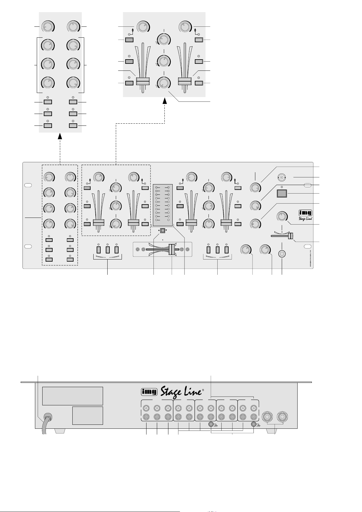
1.1 Frontplatte (Abb. 1)
[Aus Gründen der Übersichtlichkeit sind in der Abb.1
nur die ersten beiden Stereo-Eingangskanäle CH 1
und CH 2 mit Positionsnummern (6 – 11) versehen.
Die Kanäle CH3 und CH4 sind identisch.]
1 Pegelregler für die Mikrofonkanäle
2 3fache Klangregelung (max. ±15dB) für die Mi-
krofonkanäle:
HIGH = Höhen, MID = Mitten, BASS = Tiefen
3 Tasten AUTOTALK für die Talkover-Funktion:
Ist die T aste eines Mikrofonkanals gedrückt, werden bei Mikrofondurchsagen über diesen Kanal
die Pegel der Eingangskanäle CH1–CH4 automatisch um 15dB abgesenkt.
4 Tasten ECHO zum Ein-/Ausschalten der Echo-
funktion für die Mikrofonkanäle
5 Tasten ON AIR zum Ein-/Ausschalten der Mikro-
fonkanäle
6 Gain-Regler zum Einstellen der Eingangsver-
stärkung für die Stereo-Eingangskanäle
7 Umschalttasten zum Auswählen der Eingänge
der Stereo-Eingangskanäle
Taste nicht gedrückt ( ):
Eingang PHONO (Kanal CH1 und CH3) bzw.
CD (Kanal CH2 und CH4) ist angewählt
T aste gedrückt ( ); LED über der Taste leuchtet:
Eingang LINE des Kanals ist angewählt
8 Tasten ECHO zum Ein-/Ausschalten der Echo-
funktion für die Stereo-Eingangskanäle
9 Pegelregler (Fader) für die Stereo-Eingangs-
kanäle
10 Tasten PFL zum Vorhören der Stereo-Eingangs-
kanäle vor den Kanalfadern (9) über einen an
der Buchse (26) angeschlossenen Kopfhörer
11 3fache Klangregelung (max. +15dB /
-
30dB) jeweils für die Kanalgruppe CH1/CH2 und die Kanalgruppe CH3/CH4:
HIGH = Höhen, MID = Mitten, BASS = Tiefen
12 Regler REPEAT für die Echoeffekt-Funktion:
Einstellung der Anzahl der Echos
13 BNC-Buchse LAMP zum Anschluß einer Pult-
leuchte (12V/5W max.)
14 Regler TIME für die Echoeffekt-Funktion:
Einstellung der Echogeschwindigkeit
15 Ein-/Ausschalter POWER
16 Regler LEVEL für die Echoeffekt-Funktion:
Einstellung des Verhältnisses von Direkt-/Effektsignal (Einstellung der Effektintensität)
17 Pegelregler für den Kopfhörerausgang (26)
18 Regler MIX für den Kopfhörerausgang (26) und
das VU-Meter (22)
Position „PFL“ (Regler ganz links):
der Pre Fader-Pegel des Eingangskanals, dessen Taste PFL (10) gedrückt ist, wird über den
Kopfhörer abgehört und vom VU-Meter angezeigt
Position „PGM“ (Regler ganz rechts):
das laufende Musikprogramm wird vor dem
Masterregler (24) abgehört und vom VU-Meter
angezeigt
Hinweis:
Das VU-Meter muß auf den Kopfhörerausgang
geschaltet sein [Umschalttaste (20) gedrückt].
19 Tasten CUT zum Unterdrücken bestimmter Fre-
quenzbereiche für die Kanalgruppe CH 1/ CH 2:
Bei gedrückter Taste – HIGH für die Höhen, MID
für die Mitten, BASS für die Tiefen – wird das
jeweilige Frequenzband stark abgesenkt.
20 Umschalttaste für das VU-Meter (22)
Taste nicht gedrückt „MASTER“ ( ):
VU-Meter zeigt den Masterpegel an
Taste gedrückt „PFL“ ( ):
VU-Meter zeigt entweder den Pre Fader-Pegel
des Eingangskanals, dessen Taste PFL (10)
gedrückt ist, an [Regler MIX (18) auf „PFL“]
oder das laufende Musikprogramm vor dem
Masterregler (24) [Regler MIX auf „PGM“]
21 Überblendregler (Crossfader) zum Überblenden
zwischen den beiden Kanalgruppen CH 1/ CH 2
und CH3/CH4
Please unfold page 3. Then you can always see
the operating elements and connections described.
Contents
1 Operating Elements and Connections . . 4
1.1 Front panel . . . . . . . . . . . . . . . . . . . . . . . . . 4
1.2 Rear panel . . . . . . . . . . . . . . . . . . . . . . . . . . 5
2 Safety Notes . . . . . . . . . . . . . . . . . . . . . . .5
3 Applications . . . . . . . . . . . . . . . . . . . . . . . . 5
4 Connecting the Unit . . . . . . . . . . . . . . . . . 5
5 Operation . . . . . . . . . . . . . . . . . . . . . . . . . . 6
5.1 Basic settings . . . . . . . . . . . . . . . . . . . . . . . 6
5.1.1 Basic setting of channels CH1–CH 4 . . . 6
5.1.2 Basic setting of the microphone channels 6
5.2 Crossfading function . . . . . . . . . . . . . . . . . . 6
5.3 Mixing of the audio sources . . . . . . . . . . . . 7
5.4 Adjusting the echo effect . . . . . . . . . . . . . . . 7
5.5 Talkover function . . . . . . . . . . . . . . . . . . . . . 7
5.6 Pre fader listening function (PFL) . . . . . . . . 7
5.7 Monitoring of the music programme via a
monitor system . . . . . . . . . . . . . . . . . . . . . . 7
6 Specifications . . . . . . . . . . . . . . . . . . . . . . 8
1 Operating Elements and Connections
1.1 Front panel (fig. 1)
[For reasons of a clear presentation, fig. 1 only shows
the first two stereo input channels CH 1 and CH 2
provided with position numbers (6 to 11). Channels
CH3 and CH4 are identical.]
1 Level controls for the microphone channels
2 3-way equalizer (max. ±15dB) for the micro-
phone channels: HIGH = high range, MID =
midrange, BASS = bass range
3 AUTOTALK buttons for the talkover function:
if the button of a microphone channel is pressed,
the levels of the input channels CH1 to CH4 are
automatically attenuated by 15dB in case of
microphone announcements via this channel.
4 ECHO buttons for switching on/off the echo func-
tion for the microphone channels
5 ON AIR buttons for switching on /off the micro-
phone channels
6 Gain controls for adjusting the input amplification
for the stereo input channels
7 Selector buttons for selecting the inputs of the
stereo input channels
button not pressed ( ):
the PHONO input (channels CH1 and CH3) or
CD input (channels CH2 and CH4) is selected
button pressed ( ); LED above the button lights
up:
the LINE input of the channel is selected
8 ECHO buttons for switching on/off the echo
function for the stereo input channels
9 Faders to control the levels of the stereo input
channels
10 PFL buttons for pre fader listening of the stereo
input channels ahead of the channel faders (9)
via headphones connected to the jack (26)
11 3-way equalizer (max. +15 dB /
-
30 dB) each for
the channel group CH 1/ CH 2 and the channel
group CH 3/CH 4: HIGH = high range, MID =
midrange, BASS = bass range
12 REPEAT control for the echo effect function:
adjustment of the number of echos
13 BNC jack LAMP for the connection of a console
lamp (12V/5W max.)
14 TIME control for the echo effect function:
adjustment of the echo speed
15 On/off switch POWER
16 LEVEL control for the echo effect function:
setting of the ratio of direct signal/ effect signal
(setting of the effect intensity)
17 Level control for the headphone output (26)
18 MIX control for the headphone output (26) and
the VU meter (22)
position “PFL” (control set to the left stop):
the pre fader level of the input channel of which
the PFL button (10) is pressed is monitored via
the headphones and displayed by the VU meter
position “PGM” (control set to the right stop):
the currently playing music programme is monitored ahead of the master control (24) and displayed by the VU meter
Note: The VU meter must be switched to the
headphone output [selector button (20) pressed].
19 CUT buttons for suppressing certain frequency
ranges for the channel group CH 1/CH 2: with
the button pressed – HIGH for the high range,
MID for the midrange, BASS for the bass range –
the respective frequency band is attenuated to a
large extent.
20 Selector button for the VU meter (22)
button not pressed “MASTER” ( ):
VU meter displays the master level
button pressed “PFL” ( ):
VU meter displays either the pre fader level of
the input channnel of which the PFLbutton (10)
is pressed [MIX control (18) to “PFL”] or the
currently playing music programme ahead of
the master control (24) [MIX control to “PGM”]
21 Crossfader for fading between the two channel
groups CH1/CH2 and CH3/CH4
22 Stereo VU meter
4
GB
D
A
CH

22 Stereo-VU-Meter
23 Tasten CUT zum Unterdrücken bestimmter Fre-
quenzbereiche für die Kanalgruppe CH 3 / CH4:
Bei gedrückter Taste – HIGH für die Höhen, MID
für die Mitten, BASS für die Tiefen – wird das
jeweilige Frequenzband stark abgesenkt.
24 Masterregler
25 Pegelregler für den Monitorausgang BOOTH
26 6,3-mm-Klinkenbuchse zum Anschluß eines Ste-
reo-Kopfhörers (Impedanz ≥ 2 x 8Ω)
1.2 Rückseite (Abb. 2)
27 Netzkabel zum Anschluß des Gerätes an die
Stromversorgung (230V~/50Hz)
28 Stereo-Eingänge PHONO (Cinch-Buchsen) für
die Kanäle CH 1 und CH 3 zum Anschluß von
Plattenspielern mit Magnetsystem
29 Stereo-Ausgang MASTER (Cinch-Buchsen) für
den Anschluß des Verstärkers
30 Stereo-Monitorausgang BOOTH (Cinch-Buch-
sen) zum Anschluß einer Monitoranlage
31 Stereo-Ausgang REC (Cinch-Buchsen) für den
Anschluß eines Tonaufnahmegerätes; der Aufnahmepegel ist unabhängig von der Stellung des
Masterreglers (24)
32 Stereo-Eingänge LINE und CD (Cinch-Buchsen)
für die Stereo-Eingangskanäle zum Anschluß von
Geräten mit Line-Pegel-Ausgängen (z.B. CDSpieler, MiniDisk-Recorder, Kassettenrecorder)
33 Masse-Klemmschrauben GND für an den Ka-
nälen CH 1 und CH 3 angeschlossene Plattenspieler
34 Eingänge (6,3-mm-Klinkenbuchsen, sym.) zum
Anschluß von Mono-Mikrofonen an die beiden
Mikrofonkanäle
2 Hinweise für den sicheren Gebrauch
Dieses Gerät entspricht der Richtlinie für elektromagnetische Verträglichkeit 89/ 336/EWG und der Niederspannungsrichtlinie 73/ 23/EWG.
Das Gerät wird mit lebensgefährlicher Netzspannung (230V~) versorgt. Nehmen Sie deshalb nie
selbst Eingriffe im Gerät vor. Durch unsachgemäßes Vorgehen besteht die Gefahr eines elektrischen Schlages. Außerdem erlischt beim Öffnen
des Gerätes jeglicher Garantieanspruch.
Beachten Sie auch unbedingt die folgenden Punkte:
●
Verwenden Sie das Gerät nur im Innenbereich,
und schützen Sie es vor Feuchtigkeit und Hitze
(zulässiger Einsatztemperaturbereich 0–40°C).
●
Nehmen Sie das Gerät nicht in Betrieb bzw. ziehen Sie sofort den Netzstecker aus der Steckdose, wenn:
1. sichtbare Schäden am Gerät oder an der Netzanschlußleitung vorhanden sind,
2. nach einem Sturz oder ähnlichem der Verdacht
auf einen Defekt besteht,
3. Funktionsstörungen auftreten.
Lassen Sie das Gerät in jedem Fall in einer Fachwerkstatt reparieren.
●
Eine beschädigte Netzanschlußleitung darf nur
durch den Hersteller oder durch eine autorisierte
Fachwerkstatt ersetzt werden.
●
Ziehen Sie den Netzstecker nie an der Zuleitung
aus der Steckdose.
●
Wird das Gerät zweckentfremdet, nicht richtig angeschlossen, falsch bedient oder nicht fachgerecht repariert, kann für eventuelle Schäden keine
Haftung übernommen werden.
●
Verwenden Sie zum Reinigen nur ein trockenes,
weiches Tuch, niemals Chemikalien oder W asser.
●
Soll das Gerät endgültig aus dem Betrieb genommen werden, übergeben Sie es zur Entsorgung
einem örtlichen Recyclingbetrieb.
3 Einsatzmöglichkeiten
Das Mischpult MPX-210E/ GO mit vier Stereo-Eingangskanälen, zwei Mono-Mikrofonkanälen und integrierter Echofunktion ist für beliebige DJ-Anwendungen im privaten oder professionellen Bereich
geeignet.
Das Gerät kann sowohl frei aufgestellt als auch
in ein Bedienpult eingebaut werden. Es eignet sich
ebenso für die Montage in ein Rack (482mm / 19").
Für die Rackmontage wird eine Höhe von 4HE
(= 177mm) benötigt.
4 Gerät anschließen
Vor dem Anschließen von Geräten bzw . vor dem Ändern bestehender Anschlüsse das Mischpult ausschalten.
1) Die Stereo-Tonquellen an die entsprechenden
Cinch-Eingangsbuchsen der Kanäle CH1–CH4
anschließen (weiße Buchse L = linker Kanal; rote
Buchse R = rechter Kanal):
-
Geräte mit Line-Pegel-Ausgang (z.B. MiniDiskRecorder, CD-Spieler, Kassettenrecorder) an
die Buchsen CD oder LINE (32);
-
Plattenspieler mit Magnetsystem an die Buchsen PHONO (28).
Den Masseanschluß des Plattenspielers mit
der Klemmschraube GND (33) des Kanals verbinden.
2) Mono-Mikrofone an die Klinkenbuchsen MIC 1
und MIC 2 (34) anschließen.
3) Den Eingang des Verstärkers an den Masterausgang (29) anschließen.
4) Ist eine Monitoranlage vorhanden, den Verstärker der Monitoranlage an den Ausgang BOOTH
(30) anschließen.
5) Sollen Tonaufnahmen gemacht werden, das Aufnahmegerät an den Record-Ausgang REC (31)
anschließen. Der Aufnahmepegel ist unabhängig
von der Stellung des Masterreglers (24).
6) Für eine optimale Pultbeleuchtung kann an die
BNC-Buchse LAMP (13) eine Schwanenhalsleuchte (12V/ 5 W max.) angeschlossen werden,
z. B. die Leuchte GNL-205 aus dem Programm
von „img Stage Line“. Die Leuchte wird mit dem
Mischpult ein- und ausgeschaltet.
7) Über einen Stereo-Kopfhörer kann sowohl der
Pre Fader-Pegel der Eingangskanäle CH1–CH4
23 CUT buttons for suppressing certain frequency
ranges for the channel group CH 3/ CH 4: with
the button pressed – HIGH for the high range,
MID for the midrange, BASS for the bass range –
the respective frequency band is attenuated to a
large extent.
24 Master control
25 Level control for the monitor output BOOTH
26 6.3 mm jack for the connection of stereo head-
phones (impedance ≥ 2 x 8Ω)
1.2 Rear panel (fig. 2)
27 Mains cable for the connection of the unit to the
power supply (230V~/50 Hz)
28 Stereo inputs PHONO (phono jacks) for the chan-
nels CH 1 and CH 3 for the connection of turntables with magnetic system
29 Stereo output MASTER (phono jacks) for the
connection of the amplifier
30 Stereo monitor output BOOTH (phono jacks) for
the connection of a monitor system
31 Stereo output REC (phono jacks) for the connec-
tion of an audio recording unit; the recording
level is independent of the position of the master
control (24)
32 Stereo inputs LINE and CD (phono jacks) for the
stereo input channels for the connection of units
with line level outputs (e.g. CD player, minidisk
recorder, cassette recorder)
33 Ground clamping screws GND for turntables
connected to the channels CH1 and CH3
34 Inputs (6.3 mm jacks, bal.) for the connection of
mono microphones to the two microphone channels
2 Safety Notes
This unit corresponds to the directive for electromagnetic compatibility 89/336/EEC and the low
voltage directive 73/23/EEC.
This unit uses dangerous mains voltage (230 V~).
To prevent a shock hazard, do not open the cabinet. Leave servicing to authorized, skilled personnel only. Furthermore, any guarantee claim expires if the unit has been opened.
Also observe the following items in any case:
●
The unit is designed for indoor use only. Protect it
against humidity and heat (admissible ambient
temperature range 0–40°C).
●
Do not set the unit into operation or immediately
disconnect the mains plug from the mains socket if:
1. there is visible damage to the unit or mains
cable,
2. a defect might have occurred after a drop or
similar accident,
3. there are malfunctions.
The unit must in any case be repaired by authorized, skilled personnel.
●
Adamaged mains cable must only be replaced by
the manufacturer or authorized, skilled personnel.
●
Never pull the mains plug out of the mains socket
by means of the mains cable.
●
If the unit is used for purposes other than originally
intended, if it is not connected or operated properly or not repaired in an expert way, there is no
liability for any possible damage.
●
For cleaning use a dry, soft cloth, by no means
chemicals or water.
●
If the unit is to be put out of operation definitively,
it must be disposed of in a local recycling plant.
3 Applications
The mixer MPX-210E/GO with four stereo input
channels, two mono microphone channels, and integrated echo function is suitable for any desired
private or professional DJ applications.
The unit can be placed as a table top unit as well
as be installed into a console. It is also suitable for
mounting into a rack (482mm/19"). For rack mounting a height of 4 rack spaces (= 177mm) is required.
4 Connecting the Unit
Prior to connecting units or changing existing
connections switch off the mixer.
1) Connect the stereo audio sources to the corresponding phono input jacks of the channels CH1
to CH4 (white jack L = left channel; red jack R =
right channel):
-
units with line level output (e. g. minidisk recorder, CD player, cassette recorder) to the
jacks CD or LINE (32);
-
turntables with magnetic system to the PHONO
jacks (28).
Connect the ground connection of the turntable
to the clamping screw GND (33) of the channel.
2) Connect mono microphones to the 6.3mm jacks
MIC1 and MIC2 (34).
3) Connect the input of the amplifier to the master
output (29).
4) If a monitor system is available, connect the amplifier of the monitor system to the BOOTH output
(30).
5) For audio recordings, connect the recording unit
to the record output REC (31). The recording
level is independent of the position of the master
control (24).
6) For an optimum console illumination a gooseneck
lamp (12 V/5 W max.) can be connected to the
BNC jack LAMP (13), e.g. the lamp GNL-205 of
the “img Stage Line” range. The lamp is switched
on and off with the mixer.
7) Via stereo headphones the pre fader level of the
input channels CH1 to CH4 as well as the currently playing music programme can be monitored ahead of the master control (24) (see chapter 5.6). Connect the headphones (impedance ≥
2 x 8 Ω) to the 6.3mm jack (26) on the front
panel.
8) Finally connect the plug of the mains cable (27)
to a mains socket (230V~/50Hz).
5
GB
D
A
CH
 Loading...