

IMG STAGE LINE MPX-210 Instruction Manual
Stage Line
R
MPX-210
STEREO
PRO MIXER
R
GAIN
-10
+10
HIGH
0
-10
+10
MID
0
-10
+10
BASS
0
GAIN
-10
+10
HIGH
0
-10
+10
MID
0
-10
+10
BASS
0
-10
+10
HIGH
0
-10
+10
MID
0
-10
+10
BASS
0
GAIN
0
5
10
GAIN
0
5
10
CUE CUE
-10
+10
HIGH
0
-10
+10
MID
0
-10
+10
BASS
0
GAIN
0
5
10
GAIN
0
5
10
CUE CUE
CUE
O/P
SELECT
0
10
5
LEVEL
AUTO TALK AUTO TALK
ON AIR ON AIR BASS MID HIGH BASS MID HIGH
TRIGGER
PHONES
MIC 2 CH 1 CH 2 CH 3 CH 4
+EQ+EQ
LINE / CD LINE / PHONO LINE / CDLINE / PHONO
ECLIPSE
LEFT RIGHT
+5
+3
+1
0
-1
-3
-5
-7
-10
-20
MASTER
LEFT
0
10
5
0
10
5
RIGHT
MIN MAX MIN MAX MIN MAX MIN MAX MIN MAX MIN MAX
KILL
TRIGGER
SUPER X FADER
CH 3/4CH 1/2
010
100
KILL
LAMP
12V/5W
POWER
MIC 1
BEDIENUNGSANLEITUNG • INSTRUCTION MANUAL • MODE D’EMPLOI
ISTRUZIONI PER L’USO • GEBRUIKSAANWIJZING • HANDLEIDING
MANUAL DE INSTRUCCIONES • MANUAL DE INSTRUÇÕES
BRUGSANVISNING • BRUKSANVISNING • KÄYTTÖOHJE
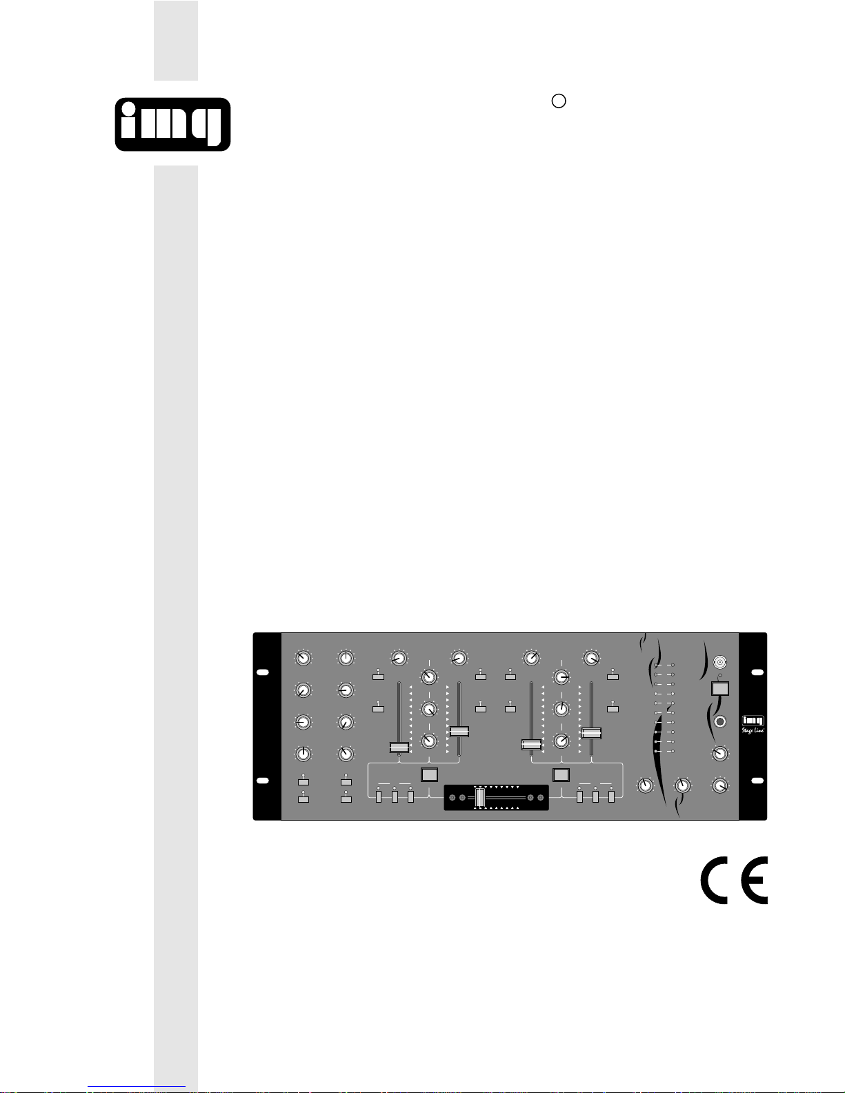
STEREO-DISCO-MISCHPULT
STEREO DISCO MIXER
TABLE DE MIXAGE STEREO POUR DISCOTHEQUE
MIXER STEREO PER DISCOTECA
MPX-210 Best.-Nr. 20.0980

2
Voordat u inschakelt ...
Wij wensen u veel plezier met uw nieuw toestel
van “img Stage Line”. Met behulp van bijgaande
gebruiksaanwijzing zal u alle functiemogelijkheden leren kennen. Door deze instructies op te
volgen zal een slechte werking vermeden worden, en zal een eventueel letsel aan uzelf en
schade aan uw toestel tengevolge van onzorgvuldig gebruik worden voorkomen.
U vindt de nederlandstalige tekst op de pagina’s
16
-
18.
NL
B
Bevor Sie einschalten ...
Wir wünschen Ihnen viel Spaß mit Ihrem neuen
Gerät von „img Stage Line“. Dabei soll Ihnen diese Bedienungsanleitung helfen, alle Funktionsmöglichkeiten kennenzulernen. Die Beachtung
der Anleitung vermeidet außerdem Fehlbedienungen und schützt Sie und Ihr Gerät vor eventuellen Schäden durch unsachgemäßen Gebrauch.
Den deutschen Text finden Sie auf den Seiten
4
-
6.
D
A
CH
Before you switch on ...
We wish you much pleasure with your new “img
Stage Line” unit. With these operating instructions you will be able to get to know all functions
of the unit. By following these instructions false
operations will be avoided, and possible damage to you and your unit due to improper use
will be prevented.
You will find the English text on pages 7
-
9.
Avant toute mise en service ...
Nous vous remercions d’avoir choisi un appareil
“img Stage Line” et vous souhaitons beaucoup
de plaisir à l’utiliser. Cette notice a pour objectif
de vous aider à mieux connaître les multiples
facettes de l’appareil et à vous éviter toute mauvaise manipulation.
La version française se trouve pages 10
-
12.
F
B
CH
Prima di accendere ...
Vi auguriamo buon divertimento con il Vostro
nuovo apparecchio “img Stage Line”. Le istruzioni per l’uso Vi possono aiutare a conoscere
tutte le possibili funzioni. E rispettando quanto
spiegato nelle istruzioni, evitate di commettere
degli errori, e così proteggete Voi stessi, ma
anche l’apparecchio, da eventuali rischi per uso
improprio.
Il testo italiano lo potete trovare alle pagine 13
-
15.
I
Antes de cualquier instalación
Tenemos de agradecerle el haber adquirido un
equipo “img Stage Line” y le deseamos un agradable uso. Este manual quiere ayudarle a conocer las multiples facetas de este equipo y evitar
cualquier uso inadecuado.
La versión española se encuentra en las páginas
19
-
21.
Inden De tænder for apparatet ...
Vi ønsker Dem god fornøjelse med Deres nye
“img Stage Line” apparat. Denne brugsanvisning
giver mulighed for at lære alle apparatets funktioner at kende. Følg vejledningen for at undgå forkert betjening og for at beskytte Dem og Deres
apparat mod skade på grund af forkert brug.
Den danske tekst finder du på side 25
-
27.
DK
E
P
S
FIN
Antes de pôr em funcionamento ...
Agradecemos-lhe por ter escolhido um aparelho
“img Stage Line”. Com estas instruções ficará
habilitado a conhecer e utilizar todas as funções
desta unidade. Seguindo-as, evita possíveis
manipulações defeituosas.
A versão em idioma português pode ser encontrada nas páginas 22
-
24.
Förskrift
Vi önskar dig mycket nöje med din nya MPX-210.
Om du först läser instruktionerna kommer du att
glädje av enheten under lång tid. Kunskap om
alla funktioner kan bespara dig mycket besvär
med enheten i framtiden.
Du finner den svenska texten på sidan 28
-
30.
Ennen virran kytkemistä ...
Toivomme, että uusi “img Stage Line”-laitteesi
tuo sinulle paljon iloa ja hyötyä. Tämä käyttöohje esittää sinulle kaikki uuden laitteesi toiminnot. Seuraamalla sitä vältät virhetoiminnot ja
niistä johtuvat mahdolliset vahingot sinulle tai
laitteellesi.
Löydät suomenkieliset käyttöohjeet sivuilta
31
-
33.
GB
3
➁
MPX-210
STEREO
PRO MIXER
R
GAIN
-10
+10
HIGH
0
-10
+10
MID
0
-10
+10
BASS
0
GAIN
-10
+10
HIGH
0
-10
+10
MID
0
-10
+10
BASS
0
-10
+10
HIGH
0
-10
+10
MID
0
-10
+10
BASS
0
GAIN
0
5
10
GAIN
0
5
10
CUE CUE
-10
+10
HIGH
0
-10
+10
MID
0
-10
+10
BASS
0
GAIN
0
5
10
GAIN
0
5
10
CUE CUE
CUE
O/P
SELECT
0
10
5
LEVEL
AUTO TALK AUTO TALK
ON AIR ON AIR BASS MID HIGH BASS MID HIGH
TRIGGER
PHONES
MIC 2 CH 1 CH 2 CH 3 CH 4
+EQ+EQ
LINE / CD LINE / PHONO LINE / CDLINE / PHONO
ECLIPSE
LEFT RIGHT
+5
+3
+1
0
-1
-3
-5
-7
-10
-20
MASTER
LEFT
0
10
5
0
10
5
RIGHT
MIN MAX MIN MAX MIN MAX MIN MAX MIN MAX MIN MAX
KILL
TRIGGER
SUPER X FADER
CH 3/4CH 1/2
010
100
KILL
LAMP
12V/5W
POWER
MIC 1
12 3 4 5 678
91011 121314 1516 1718
➀
OUTPUT CH 4 CH 3 CH 2 CH 1
MIC 2 MIC 1
REC AMP LINE CD LINE CD LINE PHONOLINE PHONO
L
R
L
R
L
R
L
R
L
R
230V~ /50Hz
GND
L
R
19 20 21 22 23 24 25

D
A
CH
4
Bitte klappen Sie die Seite 3 heraus. Sie sehen
dann immer die beschriebenen Bedienelemente
und Anschlüsse.
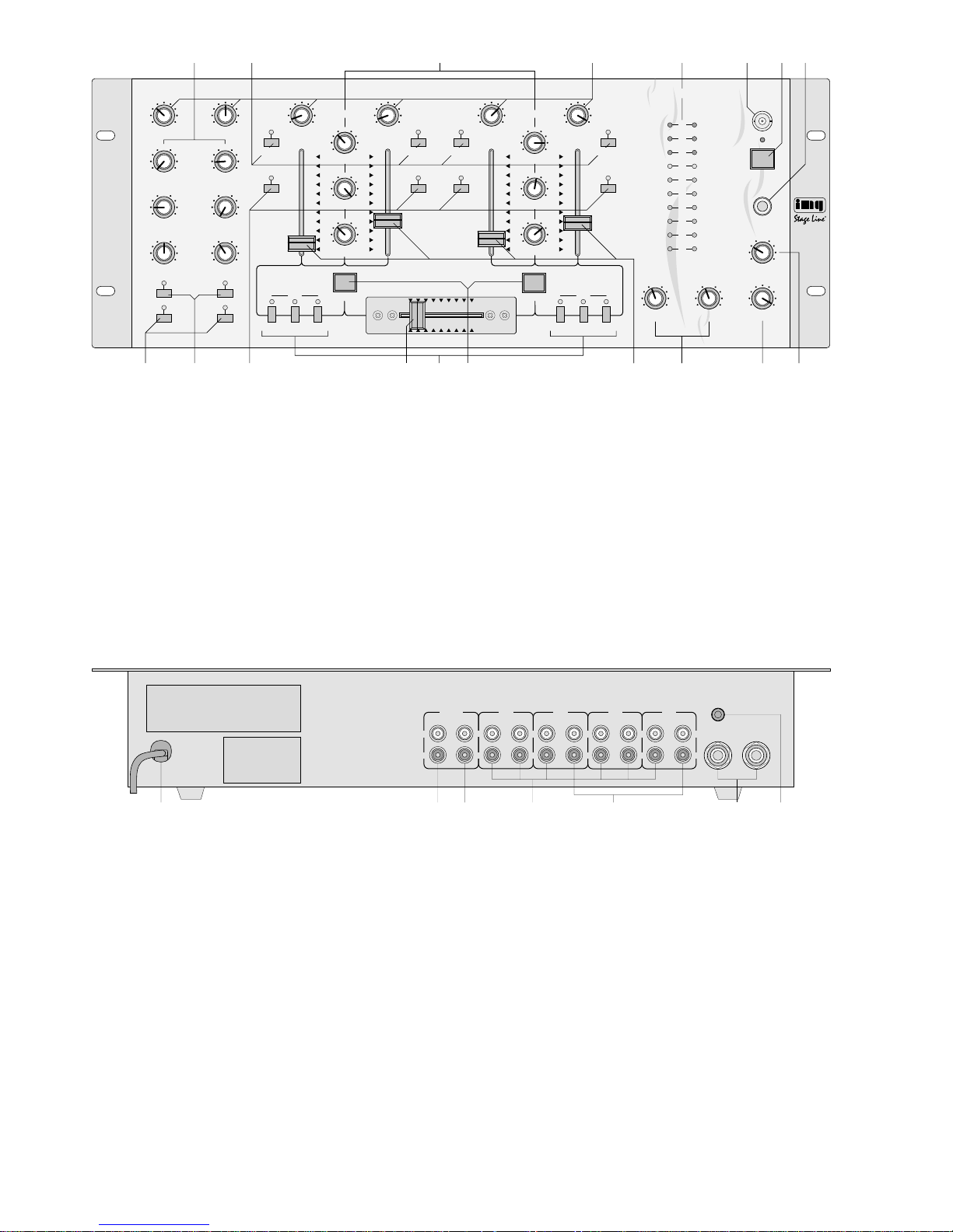
1 Übersicht der Bedienelemente und
Anschlüsse
1.1 Frontseite
1 3fache Klangregelung (Equalizer) für die Mikrofon-
kanäle; bestehend aus Tiefenregler (BASS), Mittenregler (MID) und Höhenregler (HIGH)
2 Umschalttasten für die Eingänge der Kanäle
CH1
-
CH4
Taste nicht gedrückt:
Line-Pegel (LINE)
Taste gedrückt:
Phono-Pegel (PHONO) für CH1 und CH3
Line-Pegel (CD) für CH2 und CH 4
3 3fache Klangregelung (Equalizer) für die Kanalgrup-
pe CH1/CH2 und die Kanalgruppe CH3/CH4;
bestehend aus Tiefenregler (BASS), Mittenregler
(MID) und Höhenregler (HIGH)
4 Regler GAIN zum Einstellen der Eingangsverstär-
kung für die Kanäle CH 1
-
CH 4 und die beiden
Mikrofonkanäle
5 VU-Meter
6 BNC-Buchse LAMPzum Anschluß einer Pultleuchte
(12V/5W max.)
7 Ein-/Ausschalter
8 6,3-mm-Klinkenbuchse PHONES zum Anschluß
eines Stereo-Kopfhörers (Impedanz ≥ 8 Ω)
9 Tasten ON AIR zum Ein- /Ausschalten des Mikro-
fons an Kanal MIC1 bzw. MIC2
10 T asten AUTO TALK zum Ein-/Ausschalten der T alk-
over-Funktion: Bei gedrückter Taste werden bei Mikrofondurchsagen an Kanal MIC 1 bzw. MIC2 die
Pegel der übrigen Eingangskanäle automatisch um
15dB abgesenkt.
11 Tasten CUE zum Abhören der einzelnen Eingangs-
kanäle CH1
-
CH4 über einen Kopfhörer
12 Überblendregler (Crossfader) zum Überblenden
zwischen den beiden Kanalgruppen CH1/CH2
und CH3/CH4
13 Tasten KILL für die Kanalgruppe CH 1/CH 2 und
die Kanalgruppe CH 3 / CH 4: Bei gedrückten Tasten werden für die jeweilige Kanalgruppe die Höhen (Taste HIGH), die Mitten (Taste MID) und die
Tiefen (Taste BASS) unterdrückt.
14 Taste TRIGGER für die Kanalgruppe CH1/CH2
und die Kanalgruppe CH3/CH4: zum kurzzeitigen
Einblenden der mit dem Crossfader (12) ausgeblendeten Kanalgruppe
15 Lautstärkeregler (Fader) für die Eingangskanäle
CH1
-
CH4
16 linker (LEFT) und rechter (RIGHT) Summenregler
17 Überblendregler SELECT für den Kopfhöreraus-
gang: Bei Drehen des Reglers nach links wird der
mit der Taste CUE (11) angewählte Eingangskanal
eingeblendet, bei Drehen des Reglers nach rechts
die Stereo-Summe vor den Summenreglern (16).
18 Lautstärkeregler LEVEL für den Kopfhörer an
Buchse (8)
1.2 Rückseite
19 Netzkabel zum Anschluß an 230V~/50Hz
20 Cinch-Ausgangsbuchsen REC für den Anschluß ei-
nes Tonaufnahmegerätes; der Aufnahmepegel ist
unabhängig von der Stellung der Summenregler
(16)
21 Cinch-Ausgangsbuchsen AMP für den Anschluß
eines Verstärkers
22 Cinch-Eingangsbuchsen LINE bzw. CD für die Ka-
näle CH 1
-
CH 4 zum Anschluß von Geräten mit
Line-Pegel (z. B. Tuner, CD-Spieler, Kassettenrecorder)
23 Cinch-Eingangsbuchsen PHONO für die Kanäle
CH1 und CH 3 zum Anschluß von Plattenspielern
mit Magnetsystem
24 6,3-mm-Klinkenbuchsen zum Anschluß von Mono-
Mikrofonen an die Kanäle MIC1 und MIC 2
25 Anschluß GND für gemeinsamen Massepunkt,
z.B. für Plattenspieler
2 Hinweise für den sicheren Gebrauch
Dieses Gerät entspricht der Richtlinie für elektromagnetische Verträglichkeit 89/336/EWG und der Niederspannungsrichtlinie 73/23/EWG.
Das Gerät wird mit lebensgefährlicher Netzspannung
(230 V~) versorgt. Nehmen Sie deshalb niemals
selbst Eingriffe im Gerät vor. Durch unsachgemäßes
Vorgehen besteht die Gefahr eines elektrischen
Schlages. Außerdem erlischt beim Öffnen des Gerätes jeglicher Garantieanspruch.
Beachten Sie auch unbedingt die folgenden Punkte:
●
Das Gerät ist nur zur Verwendung in Innenräumen
geeignet. Schützen Sie es vor Feuchtigkeit und Hitze (zulässiger Einsatztemperaturbereich 0
-
40°C).
●
Nehmen Sie das Gerät nicht in Betrieb, bzw. ziehen
Sie sofort den Netzstecker aus der Steckdose, wenn:
1. sichtbare Schäden am Gerät oder an der Netzanschlußleitung vorhanden sind,
2. nach einem Sturz oder ähnlichem der Verdacht
auf einen Defekt besteht,
3. Funktionsstörungen auftreten.
Lassen Sie das Gerät in jedem Fall in einer Fachwerkstatt reparieren.
●
Eine beschädigte Netzanschlußleitung darf nur
durch den Hersteller oder durch eine autorisierte
Fachwerkstatt ersetzt werden.
●
Ziehen Sie den Netzstecker nie an der Zuleitung aus
der Steckdose.
●
Wird das Gerät zweckentfremdet, nicht richtig angeschlossen, falsch bedient oder nicht fachgerecht repariert, kann für eventuelle Schäden keine Haftung
übernommen werden.
●
Verwenden Sie für die Reinigung nur ein trockenes,
weiches Tuch, niemals Wasser oder Chemikalien.
●
Soll das Gerät endgültig aus dem Betrieb genommen werden, übergeben Sie es zur Entsorgung
einem örtlichen Recyclingbetrieb.

D
A
CH
5
3 Einsatzmöglichkeiten
Das Stereo-Disco-Mischpult MPX-210 mit vier StereoEingangskanälen und zwei Mono-Mikrofonkanälen ist
für beliebige DJ-Anwendungen im privaten oder professionellen Bereich geeignet.
Das Mischpult kann frei aufgestellt werden oder in
ein Rack (482 mm/19") eingebaut werden. Für den
Rackeinbau werden 4 Höheneinheiten (1 Höheneinheit = 44,45 mm) benötigt.
4 Inbetriebnahme
1) Die Tonquellen an die entsprechenden Eingangs-
buchsen anschließen:
-
Buchsen LINE bzw. CD (22) für den Anschluß
von Geräten mit Line-Pegel (z.B. CD-Spieler,
Tuner, Kassettenrecorder)
-
Buchsen PHONO (23) für den Anschluß von
Plattenspielern mit Magnetsystem
-
Buchsen MIC1 und 2 (24) für den Anschluß von
DJ-Mono-Mikrofonen
2) Die Umschalttasten (2) für die Kanäle CH 1
-
CH4
entsprechend betätigen: Bei nicht gedrückter Taste
ist der Eingang LINE angewählt, bei gedrückter Taste der Eingang PHONO (bei den Kanälen CH1 und
CH3) bzw. der Eingang CD (bei den Kanälen CH2
und CH 4). Bei gedrückter Taste leuchtet als optische Anzeige die darüberliegende LED.
3) Den Verstärker an die Ausgangsbuchsen AMP (21)
anschließen.
4) Für eventuelle Tonaufnahmen ein Aufnahmegerät
an die Ausgangsbuchsen REC (20) anschließen.
Der Aufnahmepegel ist unabhängig von der Stellung der Summenregler (16).
5) Für eine optimale Pultbeleuchtung kann an die
Buchse LAMP (6) eine Schwanenhalsleuchte
(12V/5W max.) angeschlossen werden, z.B. GNL200 aus dem Programm von „img Stage Line“. Die
Leuchte wird mit dem Mischpult ein- und ausgeschaltet.
6) Den Netzstecker an eine Steckdose (230 V~/50 Hz)
anschließen.
7) Vor dem Einschalten des Mischpultes sollten die
Summenregler (16) auf Minimum gestellt werden,
um starke Einschaltgeräusche zu vermeiden. Dann
das Mischpult mit dem Schalter POWER (7) einschalten. Zur Anzeige der Betriebsbereitschaft leuchtet die rote LED über dem Schalter.
8) Die angeschlossenen Geräte einschalten.
5 Bedienung
Vor der ersten Inbetriebnahme alle Gain-Regler (4)
und Klangregler (1 und 3) sowie den Crossfader (12)
auf Mittelposition stellen. Die Tasten KILL (13) dürfen
nicht gedrückt sein.
5.1 Mischen der angeschlossenen Tonquellen
1) Mit den Summenreglern (16) -LEFT für den linken
Kanal, RIGHT für den rechten Kanal
-
läßt sich die
Gesamtlautstärke der angeschlossenen Tonquellen
einstellen. Zur optimalen Pegeleinstellung der an-
geschlossenen Geräte die Summenregler auf ca.
2
/3 des Maximums stellen, z. B. auf Position 7.
2) Mit den Fadern (15) die Lautstärke für die Eingangskanäle CH1
-
CH4 einstellen. Das VU-Meter
(5) zeigt den Stereo-Ausgangspegel des Summenausgangs (21) an. Bei 0 dB ist das Mischpult voll
ausgesteuert. Übersteuerungen zeigt das VU-Meter durch Aufleuchten der roten LEDs an.
Die Fader sollten nach der Pegeleinstellung auf
ca.
2
/3 des Maximums stehen, damit beim Ein- und
Ausblenden genügend Reglerweg vorhanden ist.
Sind die Fader wenig oder sehr weit aufgezogen,
müssen die Pegel durch Regulieren der Eingangsverstärkung angepaßt werden: Die GAIN-Regler (4)
der Kanäle CH 1
-
CH 4 entsprechend zurückdre-
hen bzw. aufdrehen.
3) Zum Einschalten der Mikrofone an den Kanälen
MIC 1 und MIC 2 die Tasten ON AIR (9) drücken
(LEDs über den Tasten leuchten). Mit den GAINReglern (4) der Mikrofonkanäle die gewünschte Eingangsverstärkung der Mikrofonsignale einstellen.
4) Mit der 3fachen Klangregelung
-
Regler (1) für die
Mikrofonkanäle, Regler (3) für die beiden Kanalgruppen CH1/CH2 und CH3/CH4
-
das gewünschte Klangbild für die beiden Ausgänge REC
(20) und AMP (21) einstellen: Mit den Reglern lassen sich die Tiefen (BASS), Mitten (MID) und Höhen (HIGH) um bis zu 12dB anheben bzw. absenken. Stehen die Regler in Mittelstellung, findet
keine Frequenzgangbeeinflussung statt.
Mit den KILL-Tasten (13) lassen sich für jede
Kanalgruppe die Höhen (T aste HIGH), Mitten (Taste
MID) und Tiefen (Taste BASS) unterdrücken: Bei
gedrückter Taste (LED der Taste leuchtet) wird das
jeweilige Frequenzband so stark abgesenkt, daß es
sich im Sound kaum noch bemerkbar macht. Zum
Abschalten der Kill-Funktion die entsprechende Taste erneut drücken (LED der Taste erlischt).
5) Mit dem Crossfader (12) kann zwischen den beiden
Kanalgruppen CH1/CH2 und CH3/CH4 übergeblendet werden. Steht der Crossfader in Mittelstellung, werden beide Kanalgruppen gleichzeitig
auf die Ausgänge gegeben.
Zum kurzzeitigen Einblenden der jeweils ausgeblendeten Kanalgruppe die entsprechende Taste
TRIGGER (14) dieser Kanalgruppe drücken. Solange die Taste gedrückt gehalten wird, ist die Kanalgruppe zu hören.
5.2 Vorhören der Kanäle
Über die Vorhörfunktion ist es möglich, die Eingangskanäle CH1
-
CH4 einzeln über einen Kopfhörer
abzuhören, auch wenn der dazugehörige Fader (15) auf
Minimum steht. Durch das Abhören eines Eingangskanals kann somit der günstigste Zeitpunkt zum Einblenden der entsprechenden Tonquelle gewählt werden.
Es ist ebenfalls möglich, die Stereo-Summensignale über den Kopfhörer abzuhören. Dabei ist der
Pegel der Stereo-Summe unabhängig von der Stellung der Summenregler (16).
1) Einen Stereo-Kopfhörer (Impedanz ≥ 8Ω) an die
Buchse PHONES (8) anschließen.

D
A
CH
6
2) Zum Abhören eines Eingangskanals die entsprechende Taste CUE (11) drücken (die LED über der
Taste leuchtet) und den Überblendregler SELECT
(17) ganz nach links (Markierung „CUE“) drehen.
Zum Abhören der Stereo-Summe den Überblendregler SELECTganz nach rechts (Markierung „O/P“)
drehen.
3) Mit dem Regler LEVEL (18) die gewünschte Kopfhörerlautstärke einstellen.
ACHTUNG: Stellen Sie die Kopfhörerlautstärke nie
sehr hoch ein. Hohe Lautstärken können auf Dauer
das Gehör schädigen! Das menschliche Ohr gewöhnt sich an große Lautstärken und empfindet sie
nach einiger Zeit als nicht mehr so hoch. Darum
eine hohe Lautstärke nach der Gewöhnung nicht
weiter erhöhen.
5.3 Durchsagen über das DJ-Mikrofon
Bei eingeschalteter Talkover-Funktion werden bei Mikrofondurchsagen an Kanal MIC1 bzw. MIC2 die Pegel der übrigen Eingangskanäle automatisch um 15dB
abgesenkt. Zum Einschalten der Talkover-Funktion die
Taste AUTO TALK (10) des jeweiligen Mikrofonkanals
drücken (LED über der Taste leuchtet).
Zum Abschalten der Talkover-Funktion die Taste
AUTO TALK erneut drücken (LED über der Taste erlischt).
6 Technische Daten
Eingänge
2 x Mic, Mono: . . . . . . . . . . . 1,5mV/600Ω
2 x Phono, Stereo:. . . . . . . . 2,7mV/50kΩ
6 x Line, Stereo:. . . . . . . . . . 130mV/50kΩ
Ausgänge
1 x Amp:. . . . . . . . . . . . . . . . 1V/600 Ω
1 x Record: . . . . . . . . . . . . . 0,5 V/600Ω
Allgemein
Frequenzbereich:. . . . . . . . . 20
-
20000 Hz
Klirrfaktor: . . . . . . . . . . . . . . 0,1 %
Eingangsverstärkung (Gain)
Line:. . . . . . . . . . . . . . . . . 20 dB max.
Phono: . . . . . . . . . . . . . . . 20 dB max.
Mic: . . . . . . . . . . . . . . . . . 41 dB max.
Störabstand
Eingang LINE: . . . . . . . . . 60 dB
Eingang CD: . . . . . . . . . . 59 dB
Eingang PHONO: . . . . . . 55 dB
Eingang MIC:. . . . . . . . . . 53 dB
Klangregelung
4 x Tiefen: . . . . . . . . . . . . ±12 dB/50 Hz
4 x Mitten: . . . . . . . . . . . . ±12dB/1 kHz
4 x Höhen: . . . . . . . . . . . . ±12dB/10 kHz
Talkover: . . . . . . . . . . . . . . .
-
15dB
Anschluß für Pultleuchte:. . . 12V/5 W max.
Kopfhörerausgang: . . . . . . . ≥ 8 Ω, Stereo
Zulässige
Einsatztemperatur:. . . . . . . . 0
-
40°C
Stromversorgung: . . . . . . . . 230V~/50Hz/20VA
Abmessungen (B x H x T):. . 482 x 177 x 105mm,
4 Höheneinheiten
Gewicht:. . . . . . . . . . . . . . . . 3,8kg
Anschlüsse
Mic: . . . . . . . . . . . . . . . . . . . 2 x 6,3-mm-Klinke
Kopfhörer: . . . . . . . . . . . . . . 1 x 6,3-mm-Klinke
Alle anderen
Audioanschlüsse:. . . . . . . . . 20 x Cinch
Pultleuchte: . . . . . . . . . . . . . 1 x BNC
Laut Angaben des Herstellers.
Änderungen vorbehalten.

Please unfold page 3. Then you can always see the
operating elements and connections described.
1 Operating Elements and Connections
1.1 Front panel
1 3-way equalizer for the microphone channels; con-
sisting of bass controls (BASS), midrange controls
(MID), and treble controls (HIGH)
2 Selector buttons for the inputs of the channels
CH1
-
CH4
Button not pressed:
Line level (LINE)
Button pressed:
Phono level (PHONO) for CH1 and CH 3
Line level (CD) for CH2 and CH 4
3 3-way equalizer for the channel group CH1 / CH2
and the channel group CH 3/CH 4; consisting of
bass controls (BASS), midrange controls (MID),
and treble controls (HIGH)
4 GAIN controls to adjust the input amplification for
the channels CH1
-
CH4 and both microphone
channels
5 VU meter
6 BNC jack LAMP for connecting a gooseneck lamp
(12V/5W max.)
7 On/off switch
8 6.3mm (
1
/4
") jack PHONES to connect stereo
headphones (impedance ≥ 8 Ω)
9 ON AIR buttons to switch the microphone at chan-
nel MIC1 resp. MIC 2 on/off
10 AUTO TALK buttons to switch the talkover function
on/off: If the button is pressed, the levels of all
other input channels are automatically decreased
by 15dB during microphone announcements at
channel MIC1 resp. MIC 2.
11 CUE buttons to monitor the individual input chan-
nels CH1
-
CH4 via headphones
12 Crossfader for fading between both channel groups
CH1/CH2 and CH3/CH4
13 KILL buttons for the channel group CH1/CH2 and
the channel group CH 3/CH 4: If the buttons are
pressed, the high (HIGH button), medium (MID button), and low (BASS button) frequencies of the corresponding channel group are suppressed.
14 TRIGGER button for the channel group CH1/CH2
and the channel group CH 3 /CH 4: for the shorttime fading in of the channel group faded out with
the crossfader (12)
15 Volume controls (faders) for the input channels
CH1
-
CH4
16 Left and right master control
17 SELECT crossfader for the headphones output: By
turning the control to the left, the input channel selected with the CUE button (1 1) is faded in, by turning the control to the right, the stereo master is
faded in [ahead of the master controls (16)].
18 LEVEL volume control for the headphones con-
nected to the jack (8)
1.2 Rear panel
19 Mains cable to connect to 230V~/50Hz
20 Phono output jacks REC to connect a sound re-
cording unit; the recording level is independent of
the setting of the master controls (16)
21 Phono output jacks AMPto connect an amplifier
22 Phono input jacks LINE resp. CD for the channels
CH1
-
CH 4 to connect units with line level (e. g.
tuner, CD player, tape recorder)
23 Phono input jacks PHONO for the channels CH1
and CH3 to connect turntables with magnet system
24 6.3mm (
1
/4") jacks to connect mono microphones
to channels MIC1 and MIC 2
25 GND connection for a common ground, e. g. for
turntables
2 Safety Notes
This unit corresponds to the directive for electromagnetic compatibility 89/336 /EEC and the low voltage
directive 73/23/EEC.
This unit uses lethal mains voltage (230V~). In order
to prevent a shock hazard do not open the cabinet.
Leave servicing to authorized skilled personnel only .
Furthermore, any guarantee claim expires if the unit
has been opened.
Always observe the following items:
●
The unit is only suitable for indoor use.
●
Protect the unit against humidity and heat (permissible ambient temperature range 0
-
40°C).
●
Do not take the unit into operation, or immediately
take the mains plug out of the mains socket if:
1. damage at the unit or mains cable can be seen,
2. a defect might have occurred after a drop or similar accident,
3. there are malfunctions.
The unit must in any case be repaired by authorized skilled personnel.
•
A damaged mains cable must only be repaired by
the manufacturer or authorized skilled personnel.
●
Never pull the mains plug out of the mains socket by
means of the mains cable.
●
If the unit is used for purposes other than originally
intended, if it is not connected properly, if it is operated in the wrong way or not repaired by authorized
skilled personnel, no liability can be taken over for
possible damage.
●
Only use a dry, soft cloth for cleaning, by no means
chemicals or water.
●
If the unit is to be put out of operation definitively,
bring it to a local recycling plant for disposal.
●
Important for U.K. Customers!
The wires in this mains lead are coloured in accordance with the following code:
blue = neutral
brown = live
As the colours of the wires in the mains lead of this
appliance may not correspond with the coloured
markings identifying the terminals in your plug, proceed as follows:
GB
7

GB
8
1. The wire which is coloured blue must be connected to the terminal in the plug which is
marked with the letter N or coloured black.
2. The wire which is coloured brown must be
connected to the terminal which is marked with
the letter L or coloured red.
3 Applications
The stereo disco mixer MPX-210 with four stereo input
channels and two mono microphone channels is suitable for various DJ applications for private or professional use.
The mixer may be used as a table top unit or may be
installed into a rack (482mm/19"). The rack installation
requires 4 rack spaces (1 rack space = 44.5mm).
4 Setting Into Operation
1) Connect the audio sources to the corresponding
input jacks:
-
LINE resp. CD jacks (22) to connect units with
line level (e.g. tuner, CD player, tape recorder)
-
PHONO jacks (23) to connect turntables with
magnet system
-
MIC1 and 2 jacks (24) to connect DJ mono
microphones
2) Press the selector buttons (2) for the channels
CH1
-
CH 4 correspondingly: If the button is not
pressed, the LINE input is selected; if the button is
pressed, the PHONO input (for channels CH1 and
CH 3) resp. the CD input (for channels CH 2 and
CH4) is selected. If the button is pressed, the LED
above the button lights as an optical indication.
3) Connect the amplifier to the AMP output jacks (21).
4) Connect a recording unit to the REC output jacks
(20) if audio recordings are desired. The recording
level is independent of the setting of the master
controls (16).
5) A gooseneck lamp (12V/5 W max.), e.g. GNL-200
of the range “img Stage Line”, may be connected to
the LAMP jack (6) for an optimum lighting of the
mixer. The lamp is switched on and off with the
mixer.
6) Connect the mains plug to a mains socket (230V~/
50Hz).
7) Prior to switching on the mixer, the master controls
(16) should be set to minimum to avoid loud switching noises. Then turn on the mixer with the POWER
switch (7). As an operating indication the red LED
above the switch lights.
8) Switch on the connected units.
5 Operation
Before taking the mixer into operation for the first time,
set all gain controls (4) and tone controls (1 and 3) as
well as the crossfader (12) to center position. The KILL
buttons (13) must not be pressed.
5.1 Mixing of the connected audio sources
1) The total volume of the connnected audio sources
can be adjusted with the master controls (16)
-
LEFT for the left channel, RIGHT for the right channel. For the optimum level adjustment of the connected units, set the master controls to approx.
2
/3
of the maximum, e.g. position 7.
2) Adjust the volume of the input channels CH1
-
CH4
with the faders (15). The VU meter (5) displays the
stereo output level of the master output (21). At 0dB
the mixer is at its rated maximum output. Overloads
are indicated via the VU meter by lighting of the red
LEDs.
The faders should be at approx.
2
/3 of the maximum after the level adjustment so that there is sufficient control range for fading in and out. If the
faders are almost at minimum or maximum position,
the levels have to be matched by adjusting the input
amplification: Turn up resp. turn back the GAIN controls (4) of channels CH1
-
CH4 correspondingly.
3) To switch on the microphones at channels MIC 1
and MIC2, press the ON AIR buttons (9) (the LEDs
above the buttons light). Adjust the desired input
amplification for the microphone signals with the
GAIN controls (4) of the microphone channels.
4) Adjust the desired sound characteristic for the outputs REC (20) and AMP (21) with the 3-way equalizer
-
controls (1) for the microphone channels,
controls (3) for both channel groups CH1/CH2 and
CH3/CH4: With the controls, the low (BASS),
medium (MID), and high (HIGH) frequencies can be
increased resp. decreased by 12dB. The frequency
response is not affected if the controls are in center
position.
The high (HIGH button), medium (MID button),
and low (BASS button) frequencies of each channel
group can be suppressed via the KILL buttons (13):
If the button is pressed (LED of the button lights),
the corresponding frequency band is strongly decreased so that it will barely be heard in the sound.
T o deactivate the kill function, press the corresponding button again (LED of the button extinguishes).
5) Fading between both channel groups CH 1/CH2
and CH3/ CH 4 is possible via the crossfader (12).
Both channel groups are fed to the outputs simultaneously if the crossfader is in center position.
For the short-time fading in of the channel group
which is faded out, press the corresponding TRIGGER button (14) of this channel group. As long as
this button is pressed, the channel group can be
heard.
5.2 Monitoring of the channels
Via the monitoring function it is possible to monitor the
input channels CH1
-
CH4 individually via headphones even if the corresponding fader (15) is at minimum. By monitoring of an input channel the best
moment for fading in the corresponding audio source
can thus be selected.
It is also possible to monitor the stereo master signals via headphones. The level of the stereo master is
independent of the setting of the master controls (16).
1) Connect stereo headphones (impedance ≥ 8Ω) to
the PHONES jack (8).
2) To monitor an input channel, press the correspond-
ing CUE button (11) (the LED above the button

lights) and turn the SELECT crossfader (17) completely to the left (“CUE” marking).
For monitoring the stereo master, turn the SELECT
crossfader completely to the right (“O/P” marking).
3) Adjust the desired headphones volume with the
LEVEL control (18).
CAUTION: Do not adjust the headphones to a high
volume. Permanent high volumes may damage a
person´s hearing! The human ear gets accustomed
to high volumes which do not seem to be that high
after some time. Therefore, do not further increase
a high volume after getting used to it.
5.3 Announcements via the DJ microphone
If the talkover function is activated, the levels of all
other input channels are automatically decreased by
15 dB during microphone announcements at channel
MIC 1 resp. MIC 2. To activate the talkover function,
press the AUT O T ALK button (10) of the corresponding
microphone channel (LED above the button lights).
To deactivate the talkover function, press the AUTO
T ALK button again (LED above the button extinguishes).
6 Specifications
Inputs
2 x mic, mono: . . . . . . . . . . . 1.5mV/600Ω
2 x phono, stereo: . . . . . . . . 2.7mV/50k Ω
6 x line, stereo: . . . . . . . . . . 130 mV/50kΩ
Outputs
1 x amp:. . . . . . . . . . . . . . . . 1V/600Ω
1 x record: . . . . . . . . . . . . . . 0.5 V/600Ω
General
Frequency range:. . . . . . . . . 20
-
20000 Hz
THD: . . . . . . . . . . . . . . . . . . 0.1 %
Input gain
Line:. . . . . . . . . . . . . . . . . 20 dB max.
Phono: . . . . . . . . . . . . . . . 20 dB max.
Mic: . . . . . . . . . . . . . . . . . 41 dB max.
S/N ratio
LINE input:. . . . . . . . . . . . 60 dB
CD input: . . . . . . . . . . . . . 59dB
PHONO input: . . . . . . . . . 55dB
MIC input: . . . . . . . . . . . . 53 dB
Equalizer
4 x bass: . . . . . . . . . . . . . ±12dB/50Hz
4 x mid: . . . . . . . . . . . . . . ±12dB/1 kHz
4 x treble:. . . . . . . . . . . . . ±12dB/10 kHz
Talkover: . . . . . . . . . . . . . . .
-
15dB
Connection for
gooseneck lamp: . . . . . . . . . 12 V/5W max.
Headphones output: . . . . . . ≥ 8 Ω, stereo
Permissible
ambient temperature:. . . . . . 0
-
40°C
Power supply: . . . . . . . . . . . 230V~/50Hz/20VA
Dimensions (W x H x D): . . . 482 x 177 x 105mm,
4 rack spaces
Weight:. . . . . . . . . . . . . . . . . 3.8kg
Connections
Mic: . . . . . . . . . . . . . . . . . . . 2 x 6.3mm (
1
/4") jack
Headphones: . . . . . . . . . . . . 1 x 6.3mm (
1
/4") jack
All other audio connections:. 20 x phono
Gooeseneck lamp:. . . . . . . . 1 x BNC
According to the manufacturer.
Subject to change.
GB
9

Ouvrez le présent livret page 3 de manière à visualiser les éléments et branchements.
1 Eléments et branchements
1.1 Face avant
1 Egaliseurs 3 voies pour les canaux micro avec ré-
glages graves (BASS), médiums (MID) et aigus
(HIGH)
2 Sélecteurs pour les entrées des canaux CH1
-
CH4
touche non enfoncée:
niveau Ligne (LINE)
touche enfoncée:
niveau Phono (PHONO) pour CH1 et CH 3
niveau Ligne (CD) pour CH2 et CH 4
3 Egaliseurs 3 voies pour le groupe de canaux CH1/
CH2 et le groupe CH 3/CH 4 avec réglages graves
(BASS), médiums (MID) et aigus (HIGH)
4 Potentiomètres GAIN: réglage de l’amplification
d’entrée des canaux CH1
-
CH4 et des deux ca-
naux micro
5 VU-mètre
5 Prise BNC LAMP pour brancher une lampe col de
cygne (12V/5W max.)
7 Interrupteur Marche/Arrêt
8 Prise PHONES jack 6,35: branchement d’un cas-
que stéréo (impédance ≥ 8 Ω)
9 Touches ON AIR: Marche/Arrêt du microphone sur
le canal MIC1 ou MIC 2
10 Touches AUTO TALK: Marche/Arrêt de la fonction
Talkover: si la touche est enfoncée, en cas d’annonces effectuées sur le canal MIC1 ou MIC2, le
niveau des autres canaux d’entrée est diminué automatiquement de 15dB.
11 Touches CUE: préécoute des canaux CH 1
-
CH4
dans un casque
12 Potentiomètre de fondu-enchaîné entre les deux
groupes de canaux CH1/CH2 et CH3/CH4
13 T ouches KILLpour les groupes CH1/CH2 et CH 3/
CH4: si les touches sont enfoncées, les fréquences des graves (touche BASS), médiums (touche
MID) et aigus (touche HIGH) du groupe correspondant sont supprimées.
14 Touche TRIGGER pour les groupes CH1 / CH2 et
CH3 / CH4: insertion brève du groupe utilisé pour
le fondu-enchaîné
15 Potentiomètres de réglage de volume pour les ca-
naux d’entrée CH1
-
CH4
16 Potentiomètre Master gauche (LEFT) et droit
(RIGHT)
17 Potentiomètre SELECT pour la sortie casque: en
tournant le potentiomètre vers la gauche, le canal
sélectionné avec la touche CUE (11) est inséré; en
le tournant vers la droite, c’est le Master stéréo
avant les potentiomètres Master (16).
18 Potentiomètre LEVEL: réglage de volume du cas-
que branché à la prise (8)
1.2 Face arrière
19 Cordon secteur 230V~/50Hz
20 Prises de sortie RCA REC: branchement d’un ma-
gnétophone pour effectuer des enregistrements; le
niveau d’enregistrement est indépendant de la
position des potentiomètres Master (16)
21 Prises de sortie RCAAMP pour brancher un ampli-
ficateur
22 Prises d’entrée RCA LINE ou CD pour les canaux
CH1
-
CH4: branchement d’appareils à niveau
Ligne (par exemple, tuner, lecteur CD, magnétophone)
23 Prises d’entrée RCAPHONO pour les canaux CH 1
et CH3 pour brancher des platines-disques à cellule magnétique
24 Prises jack 6,35 pour brancher des microphones
mono aux canaux MIC1 et MIC 2
25 Branchement GND pour une masse commune, par
exemple pour platine-disque
2 Conseils d’utilisation
La MPX-210 répond à la norme européenne 89 / 336 /
CEE relative à la compatibilité électromagnétique et à
la norme européenne 73 / 23 / CEE portant sur les appareils à basse tension.
La table de mixage est alimentée par une tension
très dangereuse en 230V~. Ne touchez jamais l'intérieur de l'appareil car en cas de mauvaise manipulation vous pourriez subir une décharge électrique
mortelle. En outre, l'ouverture de l'appareil rend tout
droit à la garantie caduque.
Respectez scrupuleusement les points suivants:
●
La table de mixage n’est conçue que pour une utilisation en intérieur.
●
Protégez-la de l'humidité et de la chaleur (température ambiante autorisée 0
-
40°C).
●
Ne la faites jamais fonctionner ou débranchez-la
immédiatement lorsque:
1. des dommages sur l'appareil ou le cordon secteur
apparaissent.
2. après une chute ou un cas similaire, vous avez un
doute sur l’état de l’appareil.
3. des dysfonctionnements apparaissent.
Dans tous les cas, les dommages doivent être réparés par un technicien spécialisé.
●
T out cordon secteur endommagé ne doit être remplacé que par le constructeur ou un technicien habilité.
●
Ne retirez jamais le cordon secteur de la prise en
tirant dessus.
●
Nous déclinons toute responsabilité en cas de dommage si l'appareil est utilisé dans un but autre que
celui pour lequel il a été conçu, s'il n'est pas correctement branché, utilisé ou réparé par une personne
habilitée.
●
Pour nettoyer l'appareil, utilisez un chiffon sec et
doux, en aucun cas de produits chimiques ou d'eau.
●
Lorsque l'appareil est définitivement retiré du circuit
de distribution, vous devez le déposer dans une
usine de recyclage adaptée.
F
B
CH
10

3 Possibilités d’utilisation
La table de mixage MPX-210 est équipée de quatre
canaux d’entrée stéréo et de deux entrées micro mono
et est idéale pour les DJ amateurs ou professionnels.
Elle peut être posée directement sur une table ou
installée dans un rack (482mm/ 19"). Pour une installation en rack, 4 U sont nécessaires (une unité U =
44,45mm).
4 Fonctionnement
1) Reliez les sources aux prises correspondantes:
-
prises LINE ou CD (22): branchement d’appareils à niveau Ligne (par exemple, lecteur CD,
tuner, magnétophone)
-
prises PHONO (23): branchement de platinesdisques à cellule magnétique
-
prises MIC1 et MIC 2 (24): branchement de microphones DJ mono
2) Activez les touches (2) pour les canaux CH1
-
CH4:
Si la touche n’est pas enfoncée, l’entrée LINE est
sélectionnée. Si la touche est enfoncée, l’entrée
PHONO (pour les canaux CH1 et CH3) ou l’entrée
CD (pour les canaux CH2 et CH4) est sélectionnée.
La diode située au-dessus de la touche s’allume
alors.
3) Reliez maintenant l’amplificateur aux prises de sortie AMP (21).
4) Si vous souhaitez effectuer des enregistrements,
reliez le magnétophone aux prises de sortie REC
(20). Le niveau d’enregistrement est indépendant
de la position des potentiomètres Master (16).
5) Vous pouvez brancher une lampe col de cygne
(12V/5W max.), p.ex. GNL-200 de la gamme “img
Stage Line”, à la prise LAMP(6): elle est activée par
l’interrupteur général.
6) Reliez maintenant le cordon secteur au secteur
230V~/50Hz.
7) Avant d’allumer la table, mettez les potentiomètres
Master (16) sur le minimum afin d’éviter tout bruit
fort lors de la mise sous tension. Allumez ensuite la
table avec l’interrupteur Marche /Arrêt POWER (7).
La diode rouge située au-dessus de l’interrupteur
sert de témoin de fonctionnement et s’allume.
8) Allumez ensuite les appareils reliés.
5 Utilisation
Avant la première mise en service, mettez les potentiomètres GAIN (4), les potentiomètres des égaliseurs
(1 et 3) ainsi que le potentiomètre de fondu-enchaîné
(12) sur la position médiane. Les touches KILL (13) ne
doivent pas être enfoncées.
5.1 Mixage des sources
1) Les potentiomètres Master (16) LEFT, pour le canal
gauche, et RIGHT, pour le canal droit, permettent
de régler le volume général des sources reliées.
Pour un réglage optimal des niveaux des ces
appareils, mettez les potentiomètres Master à
2
/3
environ du maximum, par exemple position 7.
2) Réglez le volume des canaux CH 1
-
CH4 avec les
potentiomètres (15). Le VU-mètre (5) indique le
niveau de sortie stéréo de la sortie Master (21). A
0 dB, la table est à pleine puissance. Toute surcharge est indiquée par les diodes rouges du VUmètre qui s’allument.
Les potentiomètres doivent être à
2
/3 environ du
maximum de manière à pouvoir effectuer correctement les fondu-enchaînés. S’ils sont déjà à leur
maximum ou minimum, adaptez les niveaux en réglant l’amplification d’entrée: tournez dans un sens
ou l’autre les potentiomètres GAIN (4) des canaux
CH1
-
CH4.
3) Pour allumer les microphones reliés aux canaux
MIC1 et MIC2, enfoncez les touches ON AIR (9) (les
diodes au-dessus des touches s’allument). Réglez
l’amplification d’entrée voulue pour les signaux micro
avec les potentiomètres GAIN (4) des canaux micro.
4) Réglez avec les égaliseurs [les potentiomètres (1)
pour les canaux micro, les potentiomètres (3) pour
les deux groupes de canaux CH 1/CH 2 et CH 3 /
CH4], les caractéristiques sonores des deux sorties
REC (20) et AMP (21). Vous pouvez ainsi augmenter ou diminuer les graves (BASS), médiums (MID)
et aigus (HIGH) de 12dB. Si les potentiomètres sont
en position médiane, il n’y a aucune modification.
Les touches KILL (13) permettent pour chaque
groupe de supprimer les fréquences des aigus (touche HIGH), médiums (touche MID) et graves (touche BASS); si la touche est enfoncée (la diode audessus de la touche s’allume), la bande passante
correspondante est diminuée de telle sorte qu’elle
est presque inaudible. Pour déconnecter la fonction
KILL, appuyez une nouvelle fois sur la touche (la
diode au-dessus de la touche s’éteint).
5) Avec le potentiomètre (12) vous pouvez effectuer
un fondu-enchaîné entre les deux groupes CH 1 /
CH2 et CH 3 / CH4. Si le potentiomètre est au milieu, les deux groupes sont dirigés simultanément
sur les sorties.
Enfoncez la touche TRIGGER (14) du groupe de
canaux utilisé pour le fondu-enchaîné pour une insertion brève de ce groupe: tant que la touche est
enfoncée, le groupe est audible.
5.2 Préécoute des canaux
Cette fonction permet d’effectuer une préécoute des
canaux d’entrée CH1-CH4 dans un casque, même
si le potentiomètre (15) du canal correspondant est sur
le minimum. Vous pouvez ainsi trouver le point idéal
pour effectuer votre fondu-enchaîné.
Il est également possible de faire une préécoute
des signaux Master stéréo; le niveau du Master stéréo
est indépendant de la position des potentiomètres
Master (16).
1) Reliez un casque stéréo (impédance ≥ 8Ω) à la
prise PHONES (8).
2) Pour effectuer une préécoute d’un canal d’entrée,
enfoncez la touche CUE (11) correspondante (la
diode au-dessus de la touche s’allume) puis tournez le potentiomètre SELECT (17) entièrement
vers la gauche (repère “CUE”).
Pour une préécoute du Master stéréo, tournez le
potentiomètre SELECTvers la droite (repère “O/P”).
F
B
CH
11
 Loading...