

IMG STAGE LINE MPX-206/SW, MPX-206 Instruction Manual
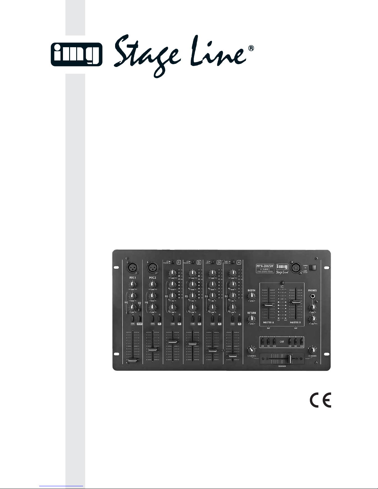
STEREO-DJ-MISCHPULT
STEREO DJ MIXER
TABLE DE MIXAGE DJ STEREO
MIXER DJ STEREO
MPX-206/SW Best.-Nr. 20.2480
BEDIENUNGSANLEITUNG • INSTRUCTION MANUAL • MODE D’EMPLOI
ISTRUZIONI PER L’USO • MANUAL DE INSTRUCCIONES • INSTRUKCJA OBSŁUGI
VEILIGHEIDSVOORSCHRIFTEN • SIKKERHEDSOPLYSNINGER • SÄKERHETSFÖRESKRIFTER • TURVALLISUUDESTA

wwwwww..iimmggssttaaggeelliinnee..ccoomm
Bevor Sie einschalten …
Wir wünschen Ihnen viel Spaß mit Ihrem neuen Gerät
von „img Stage Line“. Bitte lesen Sie diese Bedienungsanleitung vor dem Betrieb gründlich durch. Nur so lernen
Sie alle Funktionsmöglichkeiten kennen, vermeiden
Fehlbedienungen und schützen sich und Ihr Gerät vor
eventuellen Schäden durch unsachgemäßen Gebrauch.
Heben Sie die Anleitung für ein späteres Nachlesen auf.
Der deutsche Text beginnt auf der Seite 4.
Before switching on …
We wish you much pleasure with your new “img Stage
Line” unit. Please read these operating instructions carefully prior to operating the unit. Thus, you will get to know
all functions of the unit, operating errors will be prevented, and yourself and the unit will be protected
against any damage caused by improper use. Please
keep the oper ating instructions for later use.
The English text starts on page 4.
Avant toute installation …
Nous vous souhaitons beaucoup de plaisir à utiliser cet
appareil “img Stage Line”. Lisez ce mode dʼemploi entièrement avant toute utilisation. Uniquement ainsi, vous
pourrez apprendre lʼensemble des possibilités de fonctionnement de lʼappareil, éviter toute manipulation erronée
et vous protéger, ainsi que lʼappareil, de dommages éventuels engendrés par une utilisation inadaptée. Conservez la notice pour pouvoir vous y reporter ultérieurement.
La version française se trouve page 9.
Prima di accendere …
Vi auguriamo buon divertimento con il vostro nuovo
apparecchio di “img Stage Line”. Leggete attentamente
le istruzioni prima di mettere in funzione lʼapparecchio.
Solo così potete conoscere tutte le funzionalità, evitare
comandi sbagliati e proteggere voi stessi e lʼapparecchio
da eventuali danni in seguito ad un uso improprio. Conservate le istruzioni per poterle consultare anche in
futuro.
Il testo italiano inizia a pagina 9.
D
A
CH
GB
Antes de la utilización …
Le deseamos una buena utilización para su nue vo aparato “img Stage Line”. Por favor, lea estas in s trucciones
de uso atentamente antes de ha cer funcionar el aparato.
De esta manera conocerá todas las funciones de la unidad, se pre vendrán errores de operación, usted y el apa rato estarán protegidos en contra de todo daño cau sado
por un uso inadecuado. Por favor, guarde las instrucciones para una futura utilización.
La versión española comienza en la página 14.
Voor u inschakelt …
Wij wensen u veel plezier met uw nieuwe apparaat van
“img Stage Line”. Lees de veiligheidsvoorschriften grondig door, alvorens het apparaat in gebruik te nemen. Zo
behoedt u zichzelf en het apparaat voor eventuele
schade door ondeskundig gebruik. Bewaar de handleiding voor latere raadpleging.
De veiligheidsvoorschriften vindt u op pagina 20.
Przed uruchomieniem …
Życzymy zadowolenia z nowego produktu “img Stage
Line”. Dzięki tej instrukcji obsługi będą państwo w stanie
poznać wszystkie funkcje tego urządzenia. Stosując się
do instrukcji unikną państwo błędów i ewentualnego
uszkodzenia urządzenia na skutek nieprawidłowego
użytkowania. Prosimy zachować instrukcję.
Tekst polski zaczyna się na stronie 14.
Før du tænder …
Tillykke med dit nye “img Stage Line” produkt. Læs sikkerhedsanvisningerne nøje før ibrugtagning, for at
beskytte Dem og enheden mod skader, der skyldes forkert brug. Gem venligst denne betjeningsvejledning til
senere brug.
Sikkerhedsanvisningerne findes på side 20.
Innan du slår på enheten …
Vi önskar dig mycket glädje med din nya “img Stage
Line” produkt. Läs igenom säkerhetsföre skrifterna innan
en heten tas i bruk för att undvika skador till följd av
felaktig hantering. Behåll instruktionerna för framtida
bruk.
Säkerhetsföreskrifterna återfinns på sidan 21.
Ennen kytkemistä …
Toivomme Sinulle paljon miellyttäviä hetkiä uuden “img
Stage Line” laitteen kanssa. Ennen laitteen käyttöä
pyydämme Sinua huolellisesti tutustumaan turvallisuusohjeisiin. Näin vältyt vahingoilta, joita virheellinen laitteen
käyttö saattaa aiheuttaa. Ole hyvä ja säilytä käyttöohjeet
myöhempää tarvetta varten.
Turvallisuusohjeet löytyvät sivulta 21.
F
B
CH
I
E
NL
PL
DK
S FIN
B
2
3
15
12
3
4
4
5
6
7
8
9
10 11
12
10 11
12
13
14
16
17
18
19
20
21
22
23 24 25
26
27
28
34
30
31
32
33
29
35 36 37 38 39 40 41

Please unfold page 3. Then you can always see
the operating elements and connections de scribed.
Contents
1 Operating Elements and Connections . . . 4
1.1 Front plate . . . . . . . . . . . . . . . . . . . . . . . . . . 4
1.2 Rear side . . . . . . . . . . . . . . . . . . . . . . . . . . . 5
2 Safety Notes . . . . . . . . . . . . . . . . . . . . . . . . 5
3 Applications . . . . . . . . . . . . . . . . . . . . . . . . 6
4 Connection of the Mixer . . . . . . . . . . . . . . 6
4.1 Inputs . . . . . . . . . . . . . . . . . . . . . . . . . . . . . .6
4.2 Outputs . . . . . . . . . . . . . . . . . . . . . . . . . . . . 6
4.3 Connections for an effect unit . . . . . . . . . . . 6
4.4 Connections for the remote control of
CD players and turntables . . . . . . . . . . . . . . 6
4.5 Console illumination and mains voltage . . . . 6
5 Operation . . . . . . . . . . . . . . . . . . . . . . . . . . 6
5.1 Basic settings of the input channels . . . . . . . 7
5.2 Settings when using an effect unit . . . . . . . . 7
5.3 Mixing of the audio sources . . . . . . . . . . . . . 7
5.4 Crossfading between two channels/
cut function . . . . . . . . . . . . . . . . . . . . . . . . . . 7
5.5 Talkover function for the DJ microphone . . . 8
5.6 Pre fader listening (PFL) via headphones . . 8
5.7 Monitoring of the music programme
via a monitor system . . . . . . . . . . . . . . . . . . 8
5.8 Remote-controlling of turntables
and CD players . . . . . . . . . . . . . . . . . . . . . . 8
6 Specifications . . . . . . . . . . . . . . . . . . . . . . . 8
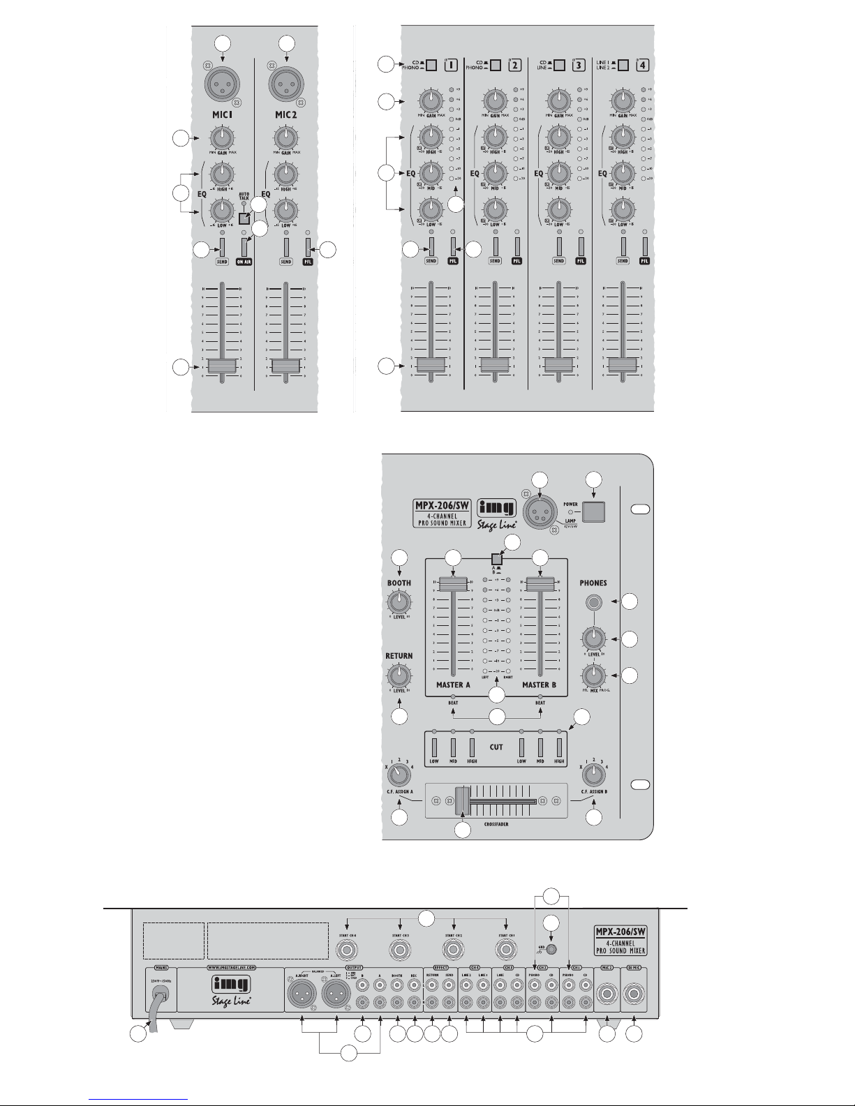
1 Operating Elements and Connections
1.1 Front plate
1 XLR input (bal.) for the connection of a DJ mono
microphone to the MIC 1 channel
[If a microphone is connected to the 6.3 mm jack
(41) of the channel, the XLR jack is switched off.]
2 XLR input (bal.) for the connection of a mono
microphone to the MIC 2 channel
[If a microphone is connected to the 6.3 mm jack
(40) of the channel, the XLR jack is switched off.]
3 Input selector switch, each for the channels CH 1
to CH 4
4 Gain control for the input amplification, each for
the MIC 1 channel, the MIC 2 channel and the
channels CH 1 to CH 4
5 3-way equalizer (max. +15 dB,
-
30 dB), each for
the channels CH 1 to CH 4: HIGH, MID, and
LOW controls
6 VU meter, each for the channels CH 1 to CH4:
display of the pre fader signal level [level
ahead
of the fader (12)]
7 2-way equalizer (max. ±15 dB), each for the MIC1
channel and the MIC 2 channel : HIGH and LOW
controls
8 AUTO TALK button for the talkover function:
If the button is pressed, the levels of the channels
CH 1 to CH 4 are attenuated by 12 dB in case of
announcements via the DJ microphone channel
9 On/ off switch ON AIR for the DJ microphone
10 SEND button, each for the MIC 1 channel, the
MIC 2 channel and the channels CH 1 to CH 4:
for switching the channel to the pre fader send
way; with the button pressed, the respective
channel is fed to the SEND output (38) ahead of
the fader (12)
11 PFL button, each for the MIC 2 channel and the
channels CH 1 to CH 4: for pre fader listening of
the channel via headphones connected to jack
(19)
12 Level control (fader), each for the MIC 1 channel,
the MIC 2 channel and the channels CH 1 to
CH 4
13 4-pole XLR jack LAMP for the connection of a
console lamp (12 V/5 W max.)
14 On/ off switch of the mixer
15 Level control for the monitor output BOOTH (35)
16 Level control (fader) for master channel A
17 Button to switch the stereo VU meter (22) be -
tween the two master channels
button not pressed:
the level of the master channel A is displayed
button pressed:
the level of the master channel B is displayed
18 Level control (fader) for master channel B
19 6.3 mm jack for the connection of stereo head-
phones (impedance ≥ 8 Ω)
20 Level control for the headphones connected to
the jack (19)
21 MIX control for the headphone output (19)
position “PFL”:
the pre fader level of the input channel of which
the PFL button (11) is pressed is monitored.
position “PROG.”:
the music programme currently playing is monitored ahead of the master faders (16 and 18).
22 Stereo VU meter; shows the level of the master
channel selected with the selector switch (17)
23 Return control for the level adjustment of the sig-
nals coming from the effect unit
24 BEAT LEDs for the two master channels; light in
a pulsating way to the rhythm of the music
Bitte klappen Sie die Seite 3 heraus. Sie sehen
dann immer die beschriebenen Bedien elemente
und Anschlüsse.
Inhalt
1 Übersicht der Bedienelemente und
Anschlüsse . . . . . . . . . . . . . . . . . . . . . . . . . 4
1.1 Frontplatte . . . . . . . . . . . . . . . . . . . . . . . . . . 4
1.2 Rückseite . . . . . . . . . . . . . . . . . . . . . . . . . . . 5
2 Hinweise für den sicheren Gebrauch . . . . 5
3 Einsatzmöglichkeiten . . . . . . . . . . . . . . . . 5
4 Mischpult anschließen . . . . . . . . . . . . . . . 6
4.1 Eingänge . . . . . . . . . . . . . . . . . . . . . . . . . . . 6
4.2 Ausgänge . . . . . . . . . . . . . . . . . . . . . . . . . . . 6
4.3 Anschlüsse für ein Effektgerät . . . . . . . . . . . 6
4.4 Anschlüsse zur Fernsteuerung von
CD-Spielern und Plattenspielern . . . . . . . . . 6
4.5 Pultbeleuchtung und Netzanschluss . . . . . . 6
5 Bedienung . . . . . . . . . . . . . . . . . . . . . . . . . 6
5.1 Grundeinstellungen der Eingangskanäle . . . 7
5.2 Einstellungen bei Verwendung eines
Effektgerätes . . . . . . . . . . . . . . . . . . . . . . . . 7
5.3 Mischen der Tonquellen . . . . . . . . . . . . . . . . 7
5.4 Überblenden zwischen zwei Kanälen/
Cut-Funktion . . . . . . . . . . . . . . . . . . . . . . . . 7
5.5 Talkover-Funktion für das DJ-Mikrofon . . . . 8
5.6 Vorhören (PFL) über einen Kopfhörer . . . . . 8
5.7 Abhören des Musikprogramms über eine
Monitoranlage . . . . . . . . . . . . . . . . . . . . . . . 8
5.8 Fernstarten von Platten- und CD-Spielern . . 8
6 Technische Daten . . . . . . . . . . . . . . . . . . . 8
1 Übersicht der Bedienelemente und
Anschlüsse
1.1 Frontplatte
1 XLR-Eingang (sym.) für den Anschluss eines DJ-
Mono-Mi krofons an den Kanal MIC 1
[Bei An schluss eines Mikrofons an die 6,3-mmKlin ken buchse (41) des Kanals wird die XLRBuch se ab g eschaltet.]
2 XLR-Eingang (sym.) für den Anschluss eines Mo -
no-Mi krofons an den Kanal MIC 2
[Bei An schluss eines Mikrofons an die 6,3-mmKlin ken buchse (40) des Kanals wird die XLRBuch se abgeschaltet.]
3 Eingangsumschalter, jeweils für die Kanäle
CH1–4
4 Gain-Regler für die Eingangsverstärkung, jeweils
für den Kanal MIC 1, den Kanal MIC 2 und die
Kanäle CH 1 –4
5 3-fache Klangregelung (max. +15 dB,
-
30 dB),
je weils für die Kanäle CH 1 – 4: Hö henregler
(HIGH), Mittenregler (MID) und Tiefenregler
(LOW)
6 VU-Meter, jeweils für die Kanäle CH 1–4: An zei -
ge des Pre-Fader-Signalpegels [Pegel
vor
dem
Fader (12)]
7 2-fache Klangregelung (max. ±15 dB), jeweils für
den Kanal MIC 1 und den Kanal MIC 2: Hö henregler (HIGH) und Tiefenregler (LOW)
8 Taste AUTO TALK für die Talkover-Funktion:
Ist die Taste gedrückt, werden bei Durch sagen
über den DJ-Mikrofon-Kanal die Pegel der Ka näle CH1–4 um 12dB abgesenkt.
9 Ein-/Ausschalter ON AIR für das DJ-Mikrofon
10 Taste SEND, jeweils für den Kanal MIC 1, den
Kanal MIC 2 und die Kanäle CH 1–4: zum Schalten des Kanals auf den Pre-Fader-Aus spiel weg;
bei gedrückter Taste wird der jeweilige Kanal vor
dem Fader (12) auf den Ausgang SEND (38)
gegeben
11 Taste PFL, jeweils für den Kanal MIC 2 und die
Kanäle CH 1 –4: zum Vorhören des Ka nals über
einen Kopfhörer an der Buchse (19)
12 Pegelregler (Fader), jeweils für den Kanal MIC 1,
den Kanal MIC 2 und die Kanäle CH1–4
13 4-polige XLR-Buchse LAMP zum Anschluss
einer Pultleuchte (12 V/5 W max.)
14 Ein-/Ausschalter des Mischpults
15 Pegelregler für den Monitorausgang BOOTH (35)
16 Pegelregler (Fader) für den Masterkanal A
17 Taste zum Umschalten des Stereo-VU-Meters
(22) zwischen den beiden Masterkanälen
Taste nicht gedrückt:
Pegel des Masterkanals A wird angezeigt
Taste gedrückt:
Pegel des Masterkanals B wird angezeigt
18 Pegelregler (Fader) für den Masterkanal B
19 6,3-mm-Klinkenbuchse zum Anschluss eines
Stereo-Kopfhörers (Impedanz ≥ 8 Ω)
20 Pegelregler für den an der Buchse (19) ange-
schlossenen Kopfhörer
21 Regler MIX für den Kopfhörerausgang (19)
Position „PFL“:
Der Pre-Fader-Pegel des Eingangskanals,
des sen Taste PFL (11) gedrückt ist, wird
abgehört.
Position „PROG.“:
Das laufende Musikprogramm wird vor den
Masterfadern (16 und 18) abgehört.
22 Stereo-VU-Meter; zeigt den Pegel des mit der
Um schalttaste (17) ge wähl ten Masterkanals an
23 Return-Regler zur Pegeleinstellung der vom Ef -
fektgerät zurückkommenden Signale
D
A
CH
4
GB
24 LEDs BEAT für die zwei Masterkanäle; leuchten
pulsierend im Rhythmus der Musik
25 CUT-Tasten zum Unterdrücken bestimmter Fre-
quenzbereiche für die zwei Ka näle, die für die
Überblendfunktion ausgewählt wurden:
Bei gedrückter Taste – HIGH für die Höhen, MID
für die Mitten, LOW für die Tiefen – wird das
jeweilige Frequenzband stark abgesenkt.
26 Zuordnungsschalter C.F. ASSIGN A für den
Cross fader (27); bestimmt, welcher der Kanäle
CH1–4eingeblendet wird, wenn der Crossfader
links steht
27 Überblendregler (Crossfader) zum Überblenden
zwischen zwei der Kanäle CH1–4 ; die jeweiligen Kanäle werden mit den beiden C.F.
ASSIGN-Schaltern (26 und 28) angewählt
28 Zuordnungsschalter C.F. ASSIGN B für den
Cross fader (27); bestimmt, welcher der Kanäle
CH1–4 eingeblendet wird, wenn der Crossfader rechts steht
1.2 Rückseite
29 6,3-mm-Klinkenbuchsen START zum Fernstar-
ten (Faderstart) von Platten- oder CD-Spielern
mit Kontaktsteuerung
30 Stereo-Eingänge PHONO (Cinch) für die Ka näle
CH 1 und CH 2 zum Anschluss von Plattenspielern mit Magnetsystem
31 Anschluss GND für einen gemeinsamen Masse-
punkt, z. B. für angeschlossene Plattenspieler
32 Netzkabel zum Anschluss des Gerätes an die
Stromversorgung (230 V~/ 50 Hz)
33 Stereo-Ausgänge des Masterkanals A – wahl-
weise XLR (sym.) oder Cinch – zum Anschluss
einer Endstufe
34 Stereo-Ausgang des Masterkanals B (Cinch)
zum Anschluss ei ner Endstufe
35 Stereo-Ausgang BOOTH (Cinch) zum An schluss
einer Monitoranlage
36 Stereo-Ausgang REC (Cinch) für den An schluss
eines Tonaufnahmegerätes; der Aufnahmepegel
ist unabhängig von der Stel lung der Masterfader
(16 und 18)
37 Stereo-Eingang RETURN (Cinch) zum An -
schluss an den Ausgang eines Effektgerätes
38 Stereo-Ausgang SEND (Cinch) zum Anschluss
an den Eingang eines Effektgerätes
39 Stereo-Eingänge LINE und CD (Cinch) für die
Ka näle CH 1–4 zum Anschluss von Geräten mit
Line-Pegel-Ausgängen (z. B. MiniDisk-Recorder,
CD-Spieler, Tapedeck)
40 6,3-mm-Klinkenbuchse (sym.) für den An schluss
eines Mono-Mi krofons an den Kanal MIC 2; bei
An schluss eines Mikrofons an diese Buchse, wird
die XLR-Buchse (2) des Kanals abgeschaltet
41 6,3-mm-Klinkenbuchse (sym.) für den An schluss
eines DJ-Mono-Mi krofons an den Kanal MIC 1;
bei An schluss eines Mikrofons an diese Buchse,
wird die XLR-Buchse (1) des Kanals abgeschaltet
2 Hinweise für den sicheren Gebrauch
Das Gerät entspricht allen erforderlichen Richtlinien
der EU und ist deshalb mit gekennzeichnet.
Beachten Sie auch unbedingt die folgenden Punkte:
G
Das Gerät ist nur zur Verwendung im Innenbereich geeignet. Schützen Sie es vor Tropf- und
Spritzwasser, hoher Luftfeuchtigkeit und Hitze
(zulässiger Einsatztemperaturbereich 0 – 40 °C).
G
Stellen Sie keine mit Flüssigkeit gefüllten Gefäße,
z. B. Trinkgläser, auf das Gerät.
G
Nehmen Sie das Gerät nicht in Betrieb bzw. ziehen Sie sofort den Netzstecker aus der Steckdose,
1. wenn sichtbare Schäden am Gerät oder an der
Netzanschlussleitung vorhanden sind,
2. wenn nach einem Sturz oder Ähnlichem der
Verdacht auf einen Defekt besteht,
3. wenn Funktionsstörungen auftreten.
Geben Sie das Gerät in jedem Fall zur Reparatur
in eine Fachwerkstatt.
G
Eine beschädigte Netzanschlussleitung darf nur
durch eine Fachwerkstatt ersetzt werden.
G
Ziehen Sie den Netzstecker nie am Kabel aus der
Steckdose, fassen Sie immer am Stecker an.
G
Verwenden Sie für die Reinigung nur ein trockenes, weiches Tuch, niemals Wasser oder Chemikalien.
G
Wird das Gerät zweckentfremdet, nicht richtig an geschlossen, falsch be dient oder nicht fachgerecht
repariert, kann keine Haftung für daraus resultierende Sach- oder Personenschäden und keine
Garantie für das Gerät übernommen werden.
3 Einsatzmöglichkeiten
Das Mischpult MPX-206/ SW mit vier Stereo-Eingangskanälen und zwei Mikrofonkanälen ist für be lie bige DJ-Anwendungen im privaten oder professionellen Bereich geeignet.
Das Gerät kann sowohl frei aufgestellt als auch in
ein Bedienpult eingebaut werden. Es eignet sich
ebenso für die Montage in ein Rack (482 mm/ 19").
Für die Rack montage wird eine Höhe von 6 HE
(1 Hö hen einheit = 44,45 mm) benötigt.
Soll das Gerät endgültig aus dem Betrieb
genommen werden, übergeben Sie es zur
umweltgerechten Entsorgung einem örtlichen Recyclingbetrieb.
WARNUNG Das Gerät wird mit lebensgefährli -
cher Netzspannung versorgt. Nehmen Sie deshalb nie selbst Eingriffe
am Gerät vor. Durch unsachgemäßes Vorgehen besteht die Gefahr
eines elektrischen Schlages.
25 CUT buttons for suppressing certain frequency
ranges for the two channels selected for the
crossfading function:
With the button pressed – HIGH for the high
range, MID for the midrange, LOW for the bass
range – the respective frequency band is attenuated to a large extent.
26 C.F. ASSIGN A switch for the crossfader (27);
de fines which of the channels CH 1 to CH 4 is
faded in if the crossfader is in the left position
27 Crossfader for fading between two of the chan-
nels CH 1 to CH 4; the respective channels are
se lected with the two C.F. ASSIGN switches (26
and 28)
28 C.F. ASSIGN B switch for the crossfader (27);
defines which of the channels CH 1 to CH 4 is
faded in if the crossfader is in the right position
1.2 Rear side
29 6.3 mm jacks START for remote starting (fader
start) of turntables or CD players with contact
control
30 Stereo inputs PHONO (phono jacks) for the
channels CH 1 and CH 2 to connect turntables
with magnetic system
31 GND connection for a common grounding point,
e. g. for connected turntables
32 Mains cable for the connection of the unit to the
power supply (230 V~/50 Hz)
33 Stereo outputs of master channel A – either XLR
jacks (bal.) or phono jacks – to connect a power
amplifier
34 Stereo output of the master channel B (phono
jacks) to connect a power amplifier
35 Stereo output BOOTH (phono jacks) to connect
a monitor system
36 Stereo output REC (phono jacks) to connect an
audio recording unit; the recording level is inde-
pendent of the position of the master faders (16
and 18)
37 Stereo input RETURN (phono jacks) for the con-
nection to the output of an effect unit
38 Stereo output SEND (phono jacks) for the con-
nection to the input of an effect unit
39 Stereo inputs LINE and CD (phono jacks) for the
channels CH 1 to CH 4 to connect units with line
level outputs (e. g. minidisk recorder, CD player,
tape deck)
40 6.3 mm jack (bal.) for the connection of a mono
microphone to the MIC 2 channel; with connection of a microphone to this jack, the XLR jack (2)
of the channel is switched off
41 6.3 mm jack (bal.) for the connection of a DJ
mono microphone to the MIC 1 channel; if a
microphone is connected to this jack, the XLR
jack (1) of the channel is switched off
2 Safety Notes
This unit corresponds to all required directives of the
EU and is therefore marked with .
Please observe the following items in any case:
G
The unit is suitable for indoor use only. Protect it
against dripping water and splash water, high air
humidity, and heat (admissible ambient temperature range 0 – 40 °C).
G
Do not place any vessel filled with liquid on the
unit, e. g. a drinking glass.
G
Do not operate the unit and immediately disconnect the mains plug from the socket
1. if the unit or the mains cable is visibly damaged,
2. if a defect might have occurred after the unit
was dropped or suffered a similar accident,
3. if malfunctions occur.
In any case the unit must be repaired by skilled
personnel.
G
A damaged mains cable must be replaced by
skilled personnel only.
G
Never pull the mains cable for disconnecting the
mains plug from the socket, always seize the plug.
G
For cleaning only use a dry, soft cloth; never use
water or chemicals.
G
No guarantee claims for the unit and no liability for
any resulting personal damage or material damage will be accepted if the unit is used for other
purposes than originally intended, if it is not correctly connected or operated, or if it is not repaired
in an expert way.
G
Important for U. K. Customers!
The wires in this mains lead are coloured in accordance with the following code:
blue = neutral
brown = live
As the colours of the wires in the mains lead of this
appliance may not correspond with the coloured
markings identifying the terminals in your plug,
proceed as follows:
1. The wire which is coloured blue must be connected to the terminal which is marked with the
letter N or coloured black.
2. The wire which is coloured brown must be connected to the terminal which is marked with the
letter L or coloured red.
If the unit is to be put out of operation de fin itively, take it to a local recycling plant for a
disposal which is not harmful to the environment.
WARNING
The unit uses dangerous mains voltage. Leave servicing to skilled personnel only. Inexpert handling may
result in electric shock.
D
A
CH
5
GB
4 Mischpult anschließen
Vor dem Anschließen von Geräten bzw. Än dern bestehender Anschlüsse das Mischpult und alle anderen Audiogeräte ausschalten oder alle Ausgangssignale auf Null stellen.
4.1 Eingänge
1) Die Tonquellen an die entsprechenden Eingangsbuchsen der Eingangskanäle an schlie ßen [MonoEingänge für die zwei Mikrofonkanäle, StereoEingänge für die Ka näle CH1–4 (weiße Buch se
L = linker Kanal, rote Buchse R = rechter Kanal)]:
– ein DJ-Mikrofon an die XLR-Buchse (1) oder an
die Klinkenbuchse (41) des Kanals MIC 1;
– ein weiteres Mikrofon an die XLR-Buchse (2)
oder an die Klinkenbuchse (40) des Kanals
MIC 2;
– Geräte mit Line-Pegel-Ausgang (z. B. CD-
Spie ler, MiniDisk-Recorder, Tapedeck) an die
Buchsen CD oder LINE (39);
– Plattenspieler mit Magnetsystem an die Buch-
sen PHONO (30). Die Klemmschraube GND
(31) kann als ge meinsamer Massepunkt ge nutzt wer den: Den Masseanschluss des Plat ten spielers mit der Klemmschraube verbinden.
2) Der Stereo-Eingang RE TURN (37) kann – sofern
er nicht für den An schluss eines Effektgerätes
vorgesehen ist (siehe Kap. 4.3) – als zusätzlicher
Eingang für eine Line-Quelle genutzt werden. Die
Si gnale des an diesen Buch sen an ge schlos senen Ge rätes werden mit dem RE TURN-Reg ler
(23) auf die Ste reo summe ge mischt.
4.2 Ausgänge
1) Die Verstärker an die entsprechenden Ausgangsbuchsen an schlie ßen:
– Die Signalsumme des Masterkanals A steht an
den beiden Stereo-Ausgängen (33) zur Verfügung; es kann wahlweise der symmetrische
XLR-Ausgang (LEFT = linker Kanal, RIGHT =
rechter Kanal) oder der asymmetrische CinchAusgang verwendet werden.
– Die Signalsumme des Masterkanals B steht am
Stereo-Ausgang B (34) zur Verfügung.
2) Ist eine Monitoranlage vorhanden, den Verstärker der Monitoranlage an den Stereo-Ausgang
BOOTH (35) anschließen.
3) Sollen Tonaufnahmen gemacht werden, das Aufnahmegerät an den Stereo-Ausgang REC (36)
anschlie ßen. Der Aufnahmepegel ist unabhängig
von der Stellung der Masterfader (16 und 18).
4) Über einen Stereo-Kopfhörer kann sowohl der
Pre-Fa der-Pegel des Mikrofonkanals MIC 2 und
der Stereo-Kanäle CH1–4als auch das ge rade
lau fende Musikprogramm vor den Ma ster fadern
ab ge hört werden (sie he Kap. 5.6). Den Kopfhörer
(Impedanz min. 8 Ω) an die Buch se (19) an schlie ßen.
4.3 Anschlüsse für ein Effektgerät
Über die Stereo-Anschlüsse SEND (38) und RE TURN (37) ist es möglich, Signale der Eingangskanäle aus dem Mischpult heraus zu füh ren, durch ein
angeschlossenes Effektgerät (z. B. Equalizer, Hallgerät) zu schleifen und wieder in das Mischpult
zurückzuführen.
Der Effekt-Send-Weg ist „Pre Fader“ geschaltet,
d. h. die Ka nal si gna le werden
vor
den Kanalfadern
(12) auf den Ef fektweg gelegt.
1) Den Eingang des Effektgerätes an die Buchsen
SEND anschließen.
2) Den Ausgang des Effektgerätes an die Buchsen
RETURN anschließen.
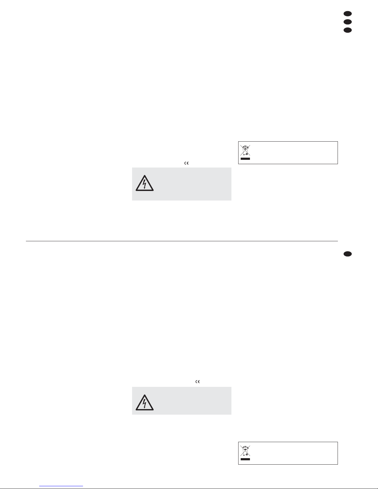
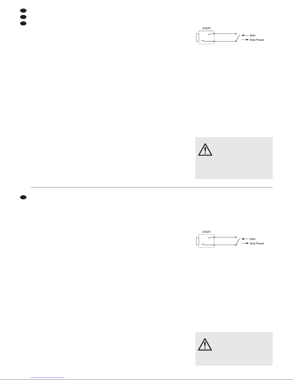
4.4 Anschlüsse zur Fernsteuerung von
CD-Spielern und Plattenspielern
Kontaktsteuerbare CD- bzw. Plattenspieler an den
Kanälen CH1–4 können über das Mischpult fern-
gestartet werden (Faderstart). Dazu den jeweiligen
Steuer eingang des angeschlossenen Gerätes mit
der entsprechenden 6,3-mm-Klinkenbuchse START
(29) des Mischpults verbinden
Abb. 4: Faderstartschalter für einen Kanal
4.5 Pultbeleuchtung und Netzanschluss
Zur Pultbeleuchtung kann an die Buchse LAMP (13)
eine Schwanenhalsleuchte (12 V/5 W max.) an ge schlossen werden, z. B. die Leuchte GNL-405 aus
dem Programm von „ img Stage Line“. Die Leuchte
wird mit dem Mischpult ein- und ausgeschaltet.
Zuletzt den Stecker des Netzkabels (32) in eine
Steckdose (230 V~/ 50 Hz) stecken.
5 Bedienung
Vor dem Einschalten sollten die Masterfader (16 und
18) und der Monitorregler BOOTH (15) auf Minimum
ge stellt werden, um Einschaltgeräusche zu vermeiden. Dann das Mischpult mit dem Schalter POWER
(14) einschalten. Zur An zei ge der Be triebs bereit schaft leuchtet die LED neben dem Schalter. An schließend die angeschlossenen Geräte einschalten.
VORSICHT Stellen Sie die Lautstärke der Audio-
anlage und die Kopfhörerlautstärke
nie sehr hoch ein. Hohe Lautstärken
können auf Dauer das Gehör schädigen! Das Ohr gewöhnt sich an hohe
Lautstärken und empfindet sie nach
einiger Zeit als nicht mehr so hoch.
Da rum erhöhen Sie eine hohe Laut stär ke nach der Gewöhnung nicht
weiter.
3 Applications
The mixer MPX-206/ SW with four stereo input channels and two microphone channels is suitable for
any private or professional DJ applications.
The unit can be used as a table top unit as well as
be installed into a console. It is suitable for mounting
into a rack (482 mm/ 19") as well. For the rack
mount ing a height of 6 rack spaces (1 rack space =
44.45 mm) is necessary.
4 Connection of the Mixer
Prior to connecting units or changing existing connections switch off the mixer and all other audio units
or set all output signals to zero.
4.1 Inputs
1) Connect the audio sources to the corresponding
input jacks of the input channels [mono inputs for
the two microphone channels, stereo inputs for
the channels CH 1 to CH4 (white jack = left chan-
nel, red jack = right channel)]:
– a DJ microphone to the XLR jack (1) or to the
6.3 mm jack (41) of the MIC 1 channel;
– a further microphone to the XLR jack (2) or to
the 6.3 mm jack (40) of the MIC 2 channel;
– units with line level output (e. g. CD player,
minidisk recorder, tape deck) to the CD or LINE
jacks (39);
– turntables with magnetic system to the PHONO
jacks (30). The clamping screw GND (31) can
be used as common grounding point: connect
the grounding connection of the turntable to the
clamping screw.
2) Unless the stereo input RETURN (37) is provided
for the connection of an effect unit (see chapter
4.3), it can be used as additional input for a line
source. The signals of the unit connected to these
jacks are mixed with the RETURN control (23) to
the stereo master.
4.2 Outputs
1) Connect the amplifiers to the corresponding output jacks:
– the master signal of master channel A is avail-
able at the two stereo outputs (33); either the
balanced XLR output or the unbalanced phono
output can be used.
– the master signal of master channel B is avail-
able at stereo output B (34).
2) If a monitor system is available, connect the
amplifier of the monitor system to the stereo output BOOTH (35).
3) For audio recordings connect the recording unit
to the stereo output REC (36). The recording
level is independent of the position of the master
faders (16 and 18).
4) Via stereo headphones the pre fader levels of
microphone channel MIC 2 and stereo channels
CH 1 to CH 4 as well as the current music programme ahead of the master faders can be monitored (see chapter 5.6). Connect the headphones
(minimum impedance 8 Ω) to the jack (19).
4.3 Connections for an effect unit
Via the stereo connections SEND (38) and RETURN
(37) it is possible to route signals of the input channels out of the mixer, to feed them through a connected effect unit (e. g. equalizer, reverberation unit)
and to feed them back to the mixer again.
The effect send way is designed “pre fader”, i. e.
the channel signals are fed to the effect way
ahead
of the channel faders (12).
1) Connect the input of the effect unit to the SEND
jacks.
2) Connect the output of the effect unit to the
RETURN jacks.
4.4 Connections for the remote control of
CD players and turntables
CD players or turntables to be contact-controlled,
connected to channels CH 1 to CH 4, can remotely
be started via the mixer (fader start). For this purpose connect the respective control input of the con nected unit to the corresponding 6.3 mm jack
START (29) of the mixer.
Fig. 4: Fader start switch for a channel
4.5 Console illumination and mains voltage
For the console illumination a gooseneck lamp (12 V/
5 W max.) can be connected to the LAMP jack (13),
e. g. the lamp GNL-405 of the “img Stage Line” range.
The lamp is switched on and off with the mixer.
Finally connect the plug of the mains cable (32) to
a mains socket (230 V~/50 Hz).
5 Operation
Prior to switching on, the master faders (16 and 18)
and the monitor control BOOTH (15) should be set to
minimum to avoid inrush noise. Then switch on the
mixer with the POWER switch (14). The LED next to
the switch lights up to indicate that the unit is ready
for operation. Then switch on the connected units.
CAUTION Never adjust the audio system or the
headphones to a very high volume.
Permanent high volumes may damage
your hearing! The human ear will get
accustomed to high volumes which do
not seem to be that high after some
time. Therefore, do not further increase
a high volume after getting used to it.
D
A
CH
6
GB

5.1 Grundeinstellung der Eingangskanäle
Die folgenden Bedienschritte dienen nur als Hilfestel lung, es sind auch andere Vorgehensweisen möglich.
1) Für eine optimale Pegeleinstellung der an den
Ein gangskanälen angeschlossenen Tonquellen
die Reg ler GAIN (4) und die Klangregler (5 und 7)
zu nächst in die Mit tel position drehen, und die
C.F. ASSIGN-Schalter (26 und 28) auf „X“ stellen
(Überblendfunktion aus).
2) Zum Einschalten des DJ-Mikrofons die Taste ON
AIR (9) drücken (LED über der Taste leuchtet).
3) Mit den Umschalttasten (3) die an den Kanälen
CH1–4 ange schlos senen Signalquellen anwählen.
4) Mit den beiden Masterfadern wird der Ge samt pegel aller an geschlossenen Tonquellen eingestellt, der an den Masterausgängen zur Ver fü gung steht: Mas ter fader A (16) für die beiden
Mas terausgänge A (33), Masterfader B (18) für
den Masterausgang B (34).
Den Regler desjenigen Masterkanals, der für
die Grundeinstellung der Eingangskanäle ge nutzt
wird, auf ca.
2
⁄3 des Maximums, z. B. auf Position 7,
stellen. Mit der Taste (17) das Stereo-VU-Meter
(22) auf den gewählten Masterkanal schalten:
Taste nicht gedrückt: Masterkanal A
Taste gedrückt: Masterkanal B
5) Zum Aussteuern eines Kanals die Fader (12) der
übrigen Kanäle auf Minimum stellen und die Tonsignale (Testsignale oder Musikstücke) auf den
jeweiligen Eingangskanal geben.
6) An hand des Stereo-VU-Meters den Pe gel des
Kanals mit seinem Kanal fader ausregeln. Op ti male Aussteuerung liegt vor, wenn bei lauten
Passagen Pegelwerte im 0-dB-Bereich an ge zeigt
werden. Leuchten die roten LEDs des VUMeters, ist der Kanal übersteuert. Der Fader
sollte nach der Pegeleinstellung auf ca.
2
⁄3 des
Maximums stehen, damit zum Ein- und Ausblenden genügend Reglerweg vorhanden ist.
Bei sehr wenig oder sehr weit aufgezogenem
Fader muss der Pegel durch Regulierung der Ein gangsverstärkung angepasst werden: Den GAINRegler (4) des Kanals entsprechend zu rück- bzw.
aufdrehen (falls erforderlich, kann er auch ganz
auf „MIN“ bzw. „MAX“ gedreht werden). Für die
Ka näle CH1–4 dienen dabei die Kanal-VU-Me ter (6) als Kontrollinstrumente: Sie zeigen für den
jeweiligen Kanal den Pegel vor dem Fader an.
7) Mit den Klangreglern des Kanals das ge wünsch te
Klangbild einstellen: Für die Kanäle CH 1 –4 lassen sich mit der 3-fa chen Klang regelung (5) die
Höhen (HIGH), Mitten (MID) und Tiefen (LOW)
bis max. 15 dB anheben bzw. bis max. 30 dB stark
ab senken. Für die Mikrofonkanäle können mit der
2-fachen Klangregelung (7) die Höhen und Tiefen
bis max. 15 dB angehoben oder gesenkt werden.
Stehen die Regler in Mittelstellung, findet kei -
ne Frequenzgangbeeinflussung statt.
Hinweis: Klangeinstellungen wirken sich auf die Pegel
aus. Deshalb nach einer Klangregulierung den Kanalpegel anhand des Stereo-VU-Meters kontrollieren und
ggf. korrigieren.
8) Die Einstellungen für die übrigen belegten Eingangskanäle in der gleichen Wei se wie oben be schrieben durchführen.
5.2 Einstellungen bei Verwendung eines
Effektgerätes
Alle Eingangskanäle lassen sich einzeln auf den
Effekt-Send-Weg legen (siehe dazu auch Kap. 4.3).
Der Effekt-Send-Weg ist ein Pre-Fader-Weg, die
Stellung der Kanalfader (12) hat also keinen Einfluss
auf die Stärke des Effekts.
1) Um einen Kanal auf den Ausspielweg zu schalten, die Taste SEND (10) des Kanals drücken
(LED über der Taste leuchtet).
2) Mit dem Regler RETURN (23) den Pegel einstellen, mit dem die vom Effektgerät kom menden
Signale auf die Stereosumme ge mischt werden.
5.3 Mischen der Tonquellen
1) Zum Mischen der angeschlossenen Tonquellen
die Überblendfunktion ausschalten. Dazu die
C.F. ASSIGN-Schalter (26 und 28) auf „X“ stellen.
2) Den Masterfader A (16) oder B (18) so weit aufziehen, dass das Mischungsverhältnis der Ton quellen op timal eingestellt werden kann.
3) Mit den Kanalfadern (12) das ge wünschte Laut stärkeverhältnis der Tonquellen ein stellen. Wird
ein Kanal nicht be nutzt, sollte sein Fader auf
Minimum ge stellt werden.
4) Mit den Masterfadern jeden Masterkanal anhand
des Stereo-VU-Meters (22) separat ausregeln.
Da zu das VU-Meter mit der Taste (17) auf An zeige
des jeweiligen Ma ster kanals umschalten. In der
Regel wird eine optimale Aussteuerung er reicht,
wenn die Pegelanzeige bei lauten Passagen
Werte im 0-dB-Bereich an zeigt. Ist der Aus gangspegel jedoch für das nachfolgende Ge rät zu hoch
oder zu niedrig, muss das Mastersignal entsprechend niedriger oder höher ausgesteuert werden.
Bei Musik mit pulsierenden Signalspitzen
(z. B. Techno) leuchtet die LED BEAT (24) des
jeweiligen Masterkanals im Takt der Musik auf.
5.4 Überblenden zwischen zwei Kanälen/
Cut-Funktion
1) Mit den zwei Zuordnungsschaltern C.F. ASSIGN
werden von den Stereo-Eingangskanälen CH 1 –4
die zwei Kanäle ausgewählt, zwischen de nen
über ge blen det werden soll:
Mit dem linken Schalter C.F. ASSIGN A (26) den
Kanal wählen, der eingeblendet werden soll, wenn
der Crossfader (26) nach links geschoben wird.
Mit dem rechten Schalter C.F. ASSIGN B (28) den
Ka nal wählen, der eingeblendet werden soll, wenn
der Crossfader nach rechts geschoben wird.
2) Die Fader (12) der nicht benutzten Kanäle auf
Minimum stellen und die zwei ausgewählten Ka -
5.1 Basic settings of the input channels
The following operating steps merely serve as an
aid; other procedures are also possible.
1) For an optimum level adjustment of the audio
sources connected to the input channels, turn the
GAIN controls (4) and the equalizer controls
(5 and 7) to mid-position first, and set the C.F.
ASSIGN switches (26 and 28) to “X” (crossfading
function switched off).
2) For switching on the DJ microphone, press the
ON AIR button (9) [LED above the button lights
up].
3) With the selector buttons (3) select the signal
sources connected to the channels CH 1 to CH4.
4) With the two master faders the total level of all
connected audio sources is adjusted which is
available at the master outputs: master fader A
(16) for the two master outputs A (33), master
fader B (18) for the master output B (34).
Set the control of the master channel which is
used for the basic setting of the input channels to
approx.
2
⁄3 of the maximum, e. g. to position 7.
Switch the stereo VU meter (22) to the selected
master channel with the button (17):
button not pressed: master channel A
button pressed: master channel B
5) To control a channel, set the faders (12) of the
remaining channels to minimum and feed the
audio signals (test signals or music pieces) to the
respective input channel.
6) By means of the stereo VU meter control the level
of the channel with its channel fader. An optimum
level control is obtained if level values in the 0 dB
range are shown at high volume. If the red LEDs
of the VU meter light up, the channel is overloaded. After the level adjustment the fader
should be in approx.
2
⁄3 of the maximum position,
so that there is sufficient control range for fading
in and out.
If the fader is moved up very much or only
moved up very little, the level must be matched
by adjusting the input amplification: turn up or
turn back the GAIN control (4) of the channel correspondingly (if required, it can also be fully
turned to “MIN” or “MAX”). For the channels CH 1
to CH 4, the channel VU meters (6) serve as control meters: they show the level ahead of the
fader for the respect ive channel.
7) Adjust the desired sound with the equalizers of
the channel: For channels CH 1 to CH4, the high
range (HIGH), the midrange (MID), and the bass
range (LOW) can be boosted up to max. 15 dB or
attenuated to a large extent up to max. 30 dB with
the 3-way equalizer (5). For the microphone
channels the high and bass ranges can be
boosted or attenuated up to max. 15 dB with the
2-way equalizer (7).
If the controls are in mid-position, there is no
influence on the frequency response.
Note: Sound adustments influence the levels. Therefore, after a sound adjustment, check the channel level
by means of the stereo VU meter and correct it, if necessary.
8) Make the adjustments for the remaining connected input channels in the same way as
described above.
5.2 Settings when using an effect unit
All input channels can individually be placed on the
effect send way (for this, also see chapter 4.3). The
effect send way is a pre fader way. Therefore, the
position of the channel faders (12) does not influence the extent of the effect.
1) To send a channel to the send way, press the
SEND button (10) of the channel (LED above the
button lights up).
2) With the RETURN control (23) adjust the level by
which the signals coming from the effect unit are
mixed to the stereo master.
5.3 Mixing of the audio sources
1) To mix the connected audio sources, switch off
the crossover function. For this purpose, set the
C.F. ASSIGN switches (26 and 28) to “X”.
2) Slide up the master fader A (16) or B (18) to a
position that allows to adjust the mixing relation of
the audio sources in an optimum way.
3) Adjust the desired volume relation of the audio
sources with each other with the channel faders
(12). If a channel is not used, its fader should be
set to minimum.
4) With the master faders separately control each
master channel by means of the stereo VU meter
(22). For this switch the VU meter with the button
(17) to display the respect ive master channel.
Usually an optimum level control is obtained if the
VU meter shows values in the 0 dB range at high
volume. However, if the output level is too high or
too low for the following unit, control the master
signal accordingly to a lower or higher level.
In case of music with pulsating signal peaks
(e. g. techno) the LED BEAT (24) of the respective
master channel lights to the rhythm of the music.
5.4 Crossfading between two channels/
cut function
1) With the two C.F. ASSIGN switches the two
channels of the stereo input channels CH 1 to
CH 4 are se lected for crossfading:
With the left C.F. ASSIGN A switch (26) select the
channel for fading in if the crossfader (27) is slid
to the left.
With the right C.F. ASSIGN B switch (28) select
the channel for fading in if the crossfader is slid to
the right.
2) Set the faders (12) of the channels not used to
minimum. Obtain the optimum level control for
the two selected channels by means of their
faders (see chapter 5.1).
D
A
CH
7
GB
 Loading...